JP2012519967A - Lightweight solar cell module - Google Patents
Lightweight solar cell module Download PDFInfo
- Publication number
- JP2012519967A JP2012519967A JP2011553171A JP2011553171A JP2012519967A JP 2012519967 A JP2012519967 A JP 2012519967A JP 2011553171 A JP2011553171 A JP 2011553171A JP 2011553171 A JP2011553171 A JP 2011553171A JP 2012519967 A JP2012519967 A JP 2012519967A
- Authority
- JP
- Japan
- Prior art keywords
- solar cell
- cell module
- module according
- ionomer
- encapsulant
- Prior art date
- Legal status (The legal status is an assumption and is not a legal conclusion. Google has not performed a legal analysis and makes no representation as to the accuracy of the status listed.)
- Ceased
Links
- 239000008393 encapsulating agent Substances 0.000 claims abstract description 84
- 229920000554 ionomer Polymers 0.000 claims abstract description 75
- 239000011521 glass Substances 0.000 claims abstract description 69
- 239000010410 layer Substances 0.000 claims description 85
- 229920001577 copolymer Polymers 0.000 claims description 39
- 239000000463 material Substances 0.000 claims description 36
- 239000011241 protective layer Substances 0.000 claims description 34
- -1 poly (vinyl acetals Chemical class 0.000 claims description 26
- 239000000203 mixture Substances 0.000 claims description 25
- 239000002253 acid Substances 0.000 claims description 23
- 229910052751 metal Inorganic materials 0.000 claims description 22
- 239000002184 metal Substances 0.000 claims description 22
- 239000010409 thin film Substances 0.000 claims description 22
- 229920000642 polymer Polymers 0.000 claims description 21
- 239000002243 precursor Substances 0.000 claims description 17
- 239000000758 substrate Substances 0.000 claims description 15
- 230000002093 peripheral effect Effects 0.000 claims description 14
- 150000001732 carboxylic acid derivatives Chemical class 0.000 claims description 11
- 229910000831 Steel Inorganic materials 0.000 claims description 10
- 239000010959 steel Substances 0.000 claims description 10
- 229920002635 polyurethane Polymers 0.000 claims description 9
- 229920001200 poly(ethylene-vinyl acetate) Polymers 0.000 claims description 8
- 229920000515 polycarbonate Polymers 0.000 claims description 8
- 239000004417 polycarbonate Substances 0.000 claims description 8
- 229920000098 polyolefin Polymers 0.000 claims description 8
- 239000004814 polyurethane Substances 0.000 claims description 8
- 239000004711 α-olefin Substances 0.000 claims description 8
- 239000004793 Polystyrene Substances 0.000 claims description 6
- 229910052782 aluminium Inorganic materials 0.000 claims description 6
- XAGFODPZIPBFFR-UHFFFAOYSA-N aluminium Chemical compound [Al] XAGFODPZIPBFFR-UHFFFAOYSA-N 0.000 claims description 6
- 229920001971 elastomer Polymers 0.000 claims description 6
- 239000000806 elastomer Substances 0.000 claims description 6
- 229920002313 fluoropolymer Polymers 0.000 claims description 6
- 239000004811 fluoropolymer Substances 0.000 claims description 6
- 229920003023 plastic Polymers 0.000 claims description 6
- 239000004033 plastic Substances 0.000 claims description 6
- 229920002223 polystyrene Polymers 0.000 claims description 6
- MARUHZGHZWCEQU-UHFFFAOYSA-N 5-phenyl-2h-tetrazole Chemical compound C1=CC=CC=C1C1=NNN=N1 MARUHZGHZWCEQU-UHFFFAOYSA-N 0.000 claims description 5
- RYGMFSIKBFXOCR-UHFFFAOYSA-N Copper Chemical compound [Cu] RYGMFSIKBFXOCR-UHFFFAOYSA-N 0.000 claims description 5
- KTSFMFGEAAANTF-UHFFFAOYSA-N [Cu].[Se].[Se].[In] Chemical compound [Cu].[Se].[Se].[In] KTSFMFGEAAANTF-UHFFFAOYSA-N 0.000 claims description 5
- 239000010949 copper Substances 0.000 claims description 5
- 229910052802 copper Inorganic materials 0.000 claims description 5
- 229910021424 microcrystalline silicon Inorganic materials 0.000 claims description 5
- 229920000728 polyester Polymers 0.000 claims description 5
- 229920000915 polyvinyl chloride Polymers 0.000 claims description 5
- 239000004065 semiconductor Substances 0.000 claims description 5
- 229920002554 vinyl polymer Polymers 0.000 claims description 5
- 229920000178 Acrylic resin Polymers 0.000 claims description 4
- 239000004925 Acrylic resin Substances 0.000 claims description 4
- VYZAMTAEIAYCRO-UHFFFAOYSA-N Chromium Chemical compound [Cr] VYZAMTAEIAYCRO-UHFFFAOYSA-N 0.000 claims description 4
- 239000004698 Polyethylene Substances 0.000 claims description 4
- RTAQQCXQSZGOHL-UHFFFAOYSA-N Titanium Chemical compound [Ti] RTAQQCXQSZGOHL-UHFFFAOYSA-N 0.000 claims description 4
- 229910021417 amorphous silicon Inorganic materials 0.000 claims description 4
- 229910052804 chromium Inorganic materials 0.000 claims description 4
- 239000011651 chromium Substances 0.000 claims description 4
- 239000000975 dye Substances 0.000 claims description 4
- 239000011133 lead Substances 0.000 claims description 4
- 229920001778 nylon Polymers 0.000 claims description 4
- 229920000573 polyethylene Polymers 0.000 claims description 4
- 229920006254 polymer film Polymers 0.000 claims description 4
- 229910052719 titanium Inorganic materials 0.000 claims description 4
- 239000010936 titanium Substances 0.000 claims description 4
- 229910001369 Brass Inorganic materials 0.000 claims description 3
- 229910045601 alloy Inorganic materials 0.000 claims description 3
- 239000000956 alloy Substances 0.000 claims description 3
- 229920001400 block copolymer Polymers 0.000 claims description 3
- 239000010951 brass Substances 0.000 claims description 3
- 125000004432 carbon atom Chemical group C* 0.000 claims description 3
- 229920002301 cellulose acetate Polymers 0.000 claims description 3
- 229910021419 crystalline silicon Inorganic materials 0.000 claims description 3
- 125000004122 cyclic group Chemical group 0.000 claims description 3
- 239000003822 epoxy resin Substances 0.000 claims description 3
- LNEPOXFFQSENCJ-UHFFFAOYSA-N haloperidol Chemical compound C1CC(O)(C=2C=CC(Cl)=CC=2)CCN1CCCC(=O)C1=CC=C(F)C=C1 LNEPOXFFQSENCJ-UHFFFAOYSA-N 0.000 claims description 3
- 150000002500 ions Chemical group 0.000 claims description 3
- 229920002492 poly(sulfone) Polymers 0.000 claims description 3
- 229920000647 polyepoxide Polymers 0.000 claims description 3
- 229920002379 silicone rubber Polymers 0.000 claims description 3
- 229920000298 Cellophane Polymers 0.000 claims description 2
- GYHNNYVSQQEPJS-UHFFFAOYSA-N Gallium Chemical compound [Ga] GYHNNYVSQQEPJS-UHFFFAOYSA-N 0.000 claims description 2
- 239000004952 Polyamide Substances 0.000 claims description 2
- 229920001893 acrylonitrile styrene Polymers 0.000 claims description 2
- 150000001735 carboxylic acids Chemical class 0.000 claims description 2
- 229910052733 gallium Inorganic materials 0.000 claims description 2
- 229910021421 monocrystalline silicon Inorganic materials 0.000 claims description 2
- JFNLZVQOOSMTJK-KNVOCYPGSA-N norbornene Chemical compound C1[C@@H]2CC[C@H]1C=C2 JFNLZVQOOSMTJK-KNVOCYPGSA-N 0.000 claims description 2
- 229920000058 polyacrylate Polymers 0.000 claims description 2
- 229920002647 polyamide Polymers 0.000 claims description 2
- 229910021420 polycrystalline silicon Inorganic materials 0.000 claims description 2
- SCUZVMOVTVSBLE-UHFFFAOYSA-N prop-2-enenitrile;styrene Chemical compound C=CC#N.C=CC1=CC=CC=C1 SCUZVMOVTVSBLE-UHFFFAOYSA-N 0.000 claims description 2
- 229920000089 Cyclic olefin copolymer Polymers 0.000 claims 1
- 239000005038 ethylene vinyl acetate Substances 0.000 claims 1
- 238000000034 method Methods 0.000 description 32
- 150000001768 cations Chemical class 0.000 description 20
- 239000011229 interlayer Substances 0.000 description 18
- 230000008569 process Effects 0.000 description 18
- 239000010408 film Substances 0.000 description 17
- 238000003475 lamination Methods 0.000 description 16
- 238000012360 testing method Methods 0.000 description 12
- 235000012431 wafers Nutrition 0.000 description 12
- 239000005340 laminated glass Substances 0.000 description 10
- XEEYBQQBJWHFJM-UHFFFAOYSA-N Iron Chemical compound [Fe] XEEYBQQBJWHFJM-UHFFFAOYSA-N 0.000 description 8
- 239000000654 additive Substances 0.000 description 8
- 229920001223 polyethylene glycol Polymers 0.000 description 7
- 239000002987 primer (paints) Substances 0.000 description 7
- 239000000853 adhesive Substances 0.000 description 6
- 230000001070 adhesive effect Effects 0.000 description 6
- 238000000576 coating method Methods 0.000 description 6
- 239000002985 plastic film Substances 0.000 description 6
- 229910052708 sodium Inorganic materials 0.000 description 6
- 239000011734 sodium Substances 0.000 description 6
- DGAQECJNVWCQMB-PUAWFVPOSA-M Ilexoside XXIX Chemical compound C[C@@H]1CC[C@@]2(CC[C@@]3(C(=CC[C@H]4[C@]3(CC[C@@H]5[C@@]4(CC[C@@H](C5(C)C)OS(=O)(=O)[O-])C)C)[C@@H]2[C@]1(C)O)C)C(=O)O[C@H]6[C@@H]([C@H]([C@@H]([C@H](O6)CO)O)O)O.[Na+] DGAQECJNVWCQMB-PUAWFVPOSA-M 0.000 description 5
- 125000002843 carboxylic acid group Chemical group 0.000 description 5
- 238000006243 chemical reaction Methods 0.000 description 5
- 239000011248 coating agent Substances 0.000 description 5
- VGGSQFUCUMXWEO-UHFFFAOYSA-N Ethene Chemical compound C=C VGGSQFUCUMXWEO-UHFFFAOYSA-N 0.000 description 4
- 239000005977 Ethylene Substances 0.000 description 4
- 239000002585 base Substances 0.000 description 4
- 238000005266 casting Methods 0.000 description 4
- 238000007765 extrusion coating Methods 0.000 description 4
- 229910052742 iron Inorganic materials 0.000 description 4
- 229920006255 plastic film Polymers 0.000 description 4
- 229920000139 polyethylene terephthalate Polymers 0.000 description 4
- 239000005020 polyethylene terephthalate Substances 0.000 description 4
- NIXOWILDQLNWCW-UHFFFAOYSA-N 2-Propenoic acid Natural products OC(=O)C=C NIXOWILDQLNWCW-UHFFFAOYSA-N 0.000 description 3
- CERQOIWHTDAKMF-UHFFFAOYSA-N Methacrylic acid Chemical compound CC(=C)C(O)=O CERQOIWHTDAKMF-UHFFFAOYSA-N 0.000 description 3
- HCHKCACWOHOZIP-UHFFFAOYSA-N Zinc Chemical compound [Zn] HCHKCACWOHOZIP-UHFFFAOYSA-N 0.000 description 3
- 238000005299 abrasion Methods 0.000 description 3
- 238000004873 anchoring Methods 0.000 description 3
- 230000000712 assembly Effects 0.000 description 3
- 238000000429 assembly Methods 0.000 description 3
- 230000004888 barrier function Effects 0.000 description 3
- 150000001733 carboxylic acid esters Chemical class 0.000 description 3
- 230000032798 delamination Effects 0.000 description 3
- 238000009429 electrical wiring Methods 0.000 description 3
- 150000002148 esters Chemical class 0.000 description 3
- 238000001125 extrusion Methods 0.000 description 3
- 238000010438 heat treatment Methods 0.000 description 3
- 239000000155 melt Substances 0.000 description 3
- 150000002739 metals Chemical class 0.000 description 3
- 229920001296 polysiloxane Polymers 0.000 description 3
- 229920002620 polyvinyl fluoride Polymers 0.000 description 3
- 239000013615 primer Substances 0.000 description 3
- 229910052725 zinc Inorganic materials 0.000 description 3
- 239000011701 zinc Substances 0.000 description 3
- ZGEGCLOFRBLKSE-UHFFFAOYSA-N 1-Heptene Chemical compound CCCCCC=C ZGEGCLOFRBLKSE-UHFFFAOYSA-N 0.000 description 2
- LIKMAJRDDDTEIG-UHFFFAOYSA-N 1-hexene Chemical compound CCCCC=C LIKMAJRDDDTEIG-UHFFFAOYSA-N 0.000 description 2
- SMZOUWXMTYCWNB-UHFFFAOYSA-N 2-(2-methoxy-5-methylphenyl)ethanamine Chemical compound COC1=CC=C(C)C=C1CCN SMZOUWXMTYCWNB-UHFFFAOYSA-N 0.000 description 2
- WSSSPWUEQFSQQG-UHFFFAOYSA-N 4-methyl-1-pentene Chemical compound CC(C)CC=C WSSSPWUEQFSQQG-UHFFFAOYSA-N 0.000 description 2
- SOGAXMICEFXMKE-UHFFFAOYSA-N Butylmethacrylate Chemical class CCCCOC(=O)C(C)=C SOGAXMICEFXMKE-UHFFFAOYSA-N 0.000 description 2
- 238000005033 Fourier transform infrared spectroscopy Methods 0.000 description 2
- VZCYOOQTPOCHFL-OWOJBTEDSA-N Fumaric acid Chemical compound OC(=O)\C=C\C(O)=O VZCYOOQTPOCHFL-OWOJBTEDSA-N 0.000 description 2
- WHXSMMKQMYFTQS-UHFFFAOYSA-N Lithium Chemical compound [Li] WHXSMMKQMYFTQS-UHFFFAOYSA-N 0.000 description 2
- FYYHWMGAXLPEAU-UHFFFAOYSA-N Magnesium Chemical compound [Mg] FYYHWMGAXLPEAU-UHFFFAOYSA-N 0.000 description 2
- BAPJBEWLBFYGME-UHFFFAOYSA-N Methyl acrylate Chemical class COC(=O)C=C BAPJBEWLBFYGME-UHFFFAOYSA-N 0.000 description 2
- VVQNEPGJFQJSBK-UHFFFAOYSA-N Methyl methacrylate Chemical class COC(=O)C(C)=C VVQNEPGJFQJSBK-UHFFFAOYSA-N 0.000 description 2
- PXHVJJICTQNCMI-UHFFFAOYSA-N Nickel Chemical compound [Ni] PXHVJJICTQNCMI-UHFFFAOYSA-N 0.000 description 2
- 239000004677 Nylon Substances 0.000 description 2
- 239000004743 Polypropylene Substances 0.000 description 2
- ZLMJMSJWJFRBEC-UHFFFAOYSA-N Potassium Chemical compound [K] ZLMJMSJWJFRBEC-UHFFFAOYSA-N 0.000 description 2
- VYPSYNLAJGMNEJ-UHFFFAOYSA-N Silicium dioxide Chemical compound O=[Si]=O VYPSYNLAJGMNEJ-UHFFFAOYSA-N 0.000 description 2
- XUIMIQQOPSSXEZ-UHFFFAOYSA-N Silicon Chemical compound [Si] XUIMIQQOPSSXEZ-UHFFFAOYSA-N 0.000 description 2
- XTXRWKRVRITETP-UHFFFAOYSA-N Vinyl acetate Chemical class CC(=O)OC=C XTXRWKRVRITETP-UHFFFAOYSA-N 0.000 description 2
- 239000006096 absorbing agent Substances 0.000 description 2
- 229910052783 alkali metal Inorganic materials 0.000 description 2
- CQEYYJKEWSMYFG-UHFFFAOYSA-N butyl acrylate Chemical class CCCCOC(=O)C=C CQEYYJKEWSMYFG-UHFFFAOYSA-N 0.000 description 2
- QYMGIIIPAFAFRX-UHFFFAOYSA-N butyl prop-2-enoate;ethene Chemical compound C=C.CCCCOC(=O)C=C QYMGIIIPAFAFRX-UHFFFAOYSA-N 0.000 description 2
- 150000007942 carboxylates Chemical class 0.000 description 2
- 239000000919 ceramic Substances 0.000 description 2
- 239000003795 chemical substances by application Substances 0.000 description 2
- 238000009833 condensation Methods 0.000 description 2
- 230000005494 condensation Effects 0.000 description 2
- 239000004020 conductor Substances 0.000 description 2
- 238000001816 cooling Methods 0.000 description 2
- 230000007547 defect Effects 0.000 description 2
- 238000007872 degassing Methods 0.000 description 2
- LDCRTTXIJACKKU-ONEGZZNKSA-N dimethyl fumarate Chemical compound COC(=O)\C=C\C(=O)OC LDCRTTXIJACKKU-ONEGZZNKSA-N 0.000 description 2
- 229960004419 dimethyl fumarate Drugs 0.000 description 2
- GMSCBRSQMRDRCD-UHFFFAOYSA-N dodecyl 2-methylprop-2-enoate Chemical class CCCCCCCCCCCCOC(=O)C(C)=C GMSCBRSQMRDRCD-UHFFFAOYSA-N 0.000 description 2
- HDERJYVLTPVNRI-UHFFFAOYSA-N ethene;ethenyl acetate Chemical class C=C.CC(=O)OC=C HDERJYVLTPVNRI-UHFFFAOYSA-N 0.000 description 2
- 229920006245 ethylene-butyl acrylate Polymers 0.000 description 2
- 229920006225 ethylene-methyl acrylate Polymers 0.000 description 2
- 238000009472 formulation Methods 0.000 description 2
- 239000003365 glass fiber Substances 0.000 description 2
- VOZRXNHHFUQHIL-UHFFFAOYSA-N glycidyl methacrylate Chemical class CC(=C)C(=O)OCC1CO1 VOZRXNHHFUQHIL-UHFFFAOYSA-N 0.000 description 2
- 239000012760 heat stabilizer Substances 0.000 description 2
- PBOSTUDLECTMNL-UHFFFAOYSA-N lauryl acrylate Chemical class CCCCCCCCCCCCOC(=O)C=C PBOSTUDLECTMNL-UHFFFAOYSA-N 0.000 description 2
- 239000002346 layers by function Substances 0.000 description 2
- 229920000092 linear low density polyethylene Polymers 0.000 description 2
- 229910052744 lithium Inorganic materials 0.000 description 2
- 229920001427 mPEG Polymers 0.000 description 2
- 239000011777 magnesium Substances 0.000 description 2
- 229910052749 magnesium Inorganic materials 0.000 description 2
- QSHDDOUJBYECFT-UHFFFAOYSA-N mercury Chemical compound [Hg] QSHDDOUJBYECFT-UHFFFAOYSA-N 0.000 description 2
- 229910052753 mercury Inorganic materials 0.000 description 2
- 150000002734 metacrylic acid derivatives Chemical class 0.000 description 2
- 125000005395 methacrylic acid group Chemical group 0.000 description 2
- 238000006386 neutralization reaction Methods 0.000 description 2
- 230000003472 neutralizing effect Effects 0.000 description 2
- 230000035515 penetration Effects 0.000 description 2
- YWAKXRMUMFPDSH-UHFFFAOYSA-N pentene Chemical compound CCCC=C YWAKXRMUMFPDSH-UHFFFAOYSA-N 0.000 description 2
- 229920001155 polypropylene Polymers 0.000 description 2
- 239000011591 potassium Substances 0.000 description 2
- 229910052700 potassium Inorganic materials 0.000 description 2
- 229910052710 silicon Inorganic materials 0.000 description 2
- 239000010703 silicon Substances 0.000 description 2
- 229910052709 silver Inorganic materials 0.000 description 2
- 239000004332 silver Substances 0.000 description 2
- 238000001228 spectrum Methods 0.000 description 2
- 238000009662 stress testing Methods 0.000 description 2
- 239000002344 surface layer Substances 0.000 description 2
- 239000005341 toughened glass Substances 0.000 description 2
- VZCYOOQTPOCHFL-UHFFFAOYSA-N trans-butenedioic acid Natural products OC(=O)C=CC(O)=O VZCYOOQTPOCHFL-UHFFFAOYSA-N 0.000 description 2
- 125000000391 vinyl group Chemical group [H]C([*])=C([H])[H] 0.000 description 2
- 230000000007 visual effect Effects 0.000 description 2
- JAHNSTQSQJOJLO-UHFFFAOYSA-N 2-(3-fluorophenyl)-1h-imidazole Chemical compound FC1=CC=CC(C=2NC=CN=2)=C1 JAHNSTQSQJOJLO-UHFFFAOYSA-N 0.000 description 1
- GOXQRTZXKQZDDN-UHFFFAOYSA-N 2-Ethylhexyl acrylate Chemical class CCCCC(CC)COC(=O)C=C GOXQRTZXKQZDDN-UHFFFAOYSA-N 0.000 description 1
- OMIGHNLMNHATMP-UHFFFAOYSA-N 2-hydroxyethyl prop-2-enoate Chemical class OCCOC(=O)C=C OMIGHNLMNHATMP-UHFFFAOYSA-N 0.000 description 1
- CPPDFKVVKLWZHE-UHFFFAOYSA-N 2-methylprop-2-enoic acid;phenoxybenzene Chemical class CC(=C)C(O)=O.C=1C=CC=CC=1OC1=CC=CC=C1 CPPDFKVVKLWZHE-UHFFFAOYSA-N 0.000 description 1
- RUMACXVDVNRZJZ-UHFFFAOYSA-N 2-methylpropyl 2-methylprop-2-enoate Chemical class CC(C)COC(=O)C(C)=C RUMACXVDVNRZJZ-UHFFFAOYSA-N 0.000 description 1
- CFVWNXQPGQOHRJ-UHFFFAOYSA-N 2-methylpropyl prop-2-enoate Chemical class CC(C)COC(=O)C=C CFVWNXQPGQOHRJ-UHFFFAOYSA-N 0.000 description 1
- YHQXBTXEYZIYOV-UHFFFAOYSA-N 3-methylbut-1-ene Chemical compound CC(C)C=C YHQXBTXEYZIYOV-UHFFFAOYSA-N 0.000 description 1
- YKZUNWLMLRCVCW-UHFFFAOYSA-N 4-[2-(4-bicyclo[2.2.1]hept-2-enyl)ethyl]bicyclo[2.2.1]hept-2-ene Chemical compound C1CC(C2)C=CC21CCC1(C=C2)CC2CC1 YKZUNWLMLRCVCW-UHFFFAOYSA-N 0.000 description 1
- HAVDCTUCZNKAHY-UHFFFAOYSA-N CC(=C)C(O)=O.CCCCCCCCCc1ccc(Oc2ccc(CCCCCCCCC)cc2)cc1 Chemical class CC(=C)C(O)=O.CCCCCCCCCc1ccc(Oc2ccc(CCCCCCCCC)cc2)cc1 HAVDCTUCZNKAHY-UHFFFAOYSA-N 0.000 description 1
- OYPRJOBELJOOCE-UHFFFAOYSA-N Calcium Chemical compound [Ca] OYPRJOBELJOOCE-UHFFFAOYSA-N 0.000 description 1
- OKTJSMMVPCPJKN-UHFFFAOYSA-N Carbon Chemical compound [C] OKTJSMMVPCPJKN-UHFFFAOYSA-N 0.000 description 1
- 229920002284 Cellulose triacetate Polymers 0.000 description 1
- 229910052684 Cerium Inorganic materials 0.000 description 1
- IEPRKVQEAMIZSS-WAYWQWQTSA-N Diethyl maleate Chemical class CCOC(=O)\C=C/C(=O)OCC IEPRKVQEAMIZSS-WAYWQWQTSA-N 0.000 description 1
- JIGUQPWFLRLWPJ-UHFFFAOYSA-N Ethyl acrylate Chemical class CCOC(=O)C=C JIGUQPWFLRLWPJ-UHFFFAOYSA-N 0.000 description 1
- 229910001335 Galvanized steel Inorganic materials 0.000 description 1
- WOBHKFSMXKNTIM-UHFFFAOYSA-N Hydroxyethyl methacrylate Chemical class CC(=C)C(=O)OCCO WOBHKFSMXKNTIM-UHFFFAOYSA-N 0.000 description 1
- 239000004609 Impact Modifier Substances 0.000 description 1
- 239000006057 Non-nutritive feed additive Substances 0.000 description 1
- RRAQGPNOVYEVCW-UHFFFAOYSA-N OC(=O)C=C.C1=CC(CCCCCCCCC)=CC=C1OC1=CC=C(CCCCCCCCC)C=C1 Chemical class OC(=O)C=C.C1=CC(CCCCCCCCC)=CC=C1OC1=CC=C(CCCCCCCCC)C=C1 RRAQGPNOVYEVCW-UHFFFAOYSA-N 0.000 description 1
- CRHWZQHMAWOVCS-UHFFFAOYSA-N OC(=O)C=C.CCCCCCCCCCCCCCCCCCCCCCOCCCCCCCCCCCCCCCCCCCCCC Chemical class OC(=O)C=C.CCCCCCCCCCCCCCCCCCCCCCOCCCCCCCCCCCCCCCCCCCCCC CRHWZQHMAWOVCS-UHFFFAOYSA-N 0.000 description 1
- CBENFWSGALASAD-UHFFFAOYSA-N Ozone Chemical compound [O-][O+]=O CBENFWSGALASAD-UHFFFAOYSA-N 0.000 description 1
- 239000002033 PVDF binder Substances 0.000 description 1
- 239000004695 Polyether sulfone Substances 0.000 description 1
- 229920001328 Polyvinylidene chloride Polymers 0.000 description 1
- OFOBLEOULBTSOW-UHFFFAOYSA-N Propanedioic acid Natural products OC(=O)CC(O)=O OFOBLEOULBTSOW-UHFFFAOYSA-N 0.000 description 1
- BLRPTPMANUNPDV-UHFFFAOYSA-N Silane Chemical compound [SiH4] BLRPTPMANUNPDV-UHFFFAOYSA-N 0.000 description 1
- 239000006087 Silane Coupling Agent Substances 0.000 description 1
- BQCADISMDOOEFD-UHFFFAOYSA-N Silver Chemical compound [Ag] BQCADISMDOOEFD-UHFFFAOYSA-N 0.000 description 1
- FKNQFGJONOIPTF-UHFFFAOYSA-N Sodium cation Chemical compound [Na+] FKNQFGJONOIPTF-UHFFFAOYSA-N 0.000 description 1
- 229920010524 Syndiotactic polystyrene Polymers 0.000 description 1
- 239000004809 Teflon Substances 0.000 description 1
- 229920006362 Teflon® Polymers 0.000 description 1
- 229920006355 Tefzel Polymers 0.000 description 1
- ATJFFYVFTNAWJD-UHFFFAOYSA-N Tin Chemical compound [Sn] ATJFFYVFTNAWJD-UHFFFAOYSA-N 0.000 description 1
- 239000012963 UV stabilizer Substances 0.000 description 1
- QCWXUUIWCKQGHC-UHFFFAOYSA-N Zirconium Chemical compound [Zr] QCWXUUIWCKQGHC-UHFFFAOYSA-N 0.000 description 1
- NNLVGZFZQQXQNW-ADJNRHBOSA-N [(2r,3r,4s,5r,6s)-4,5-diacetyloxy-3-[(2s,3r,4s,5r,6r)-3,4,5-triacetyloxy-6-(acetyloxymethyl)oxan-2-yl]oxy-6-[(2r,3r,4s,5r,6s)-4,5,6-triacetyloxy-2-(acetyloxymethyl)oxan-3-yl]oxyoxan-2-yl]methyl acetate Chemical compound O([C@@H]1O[C@@H]([C@H]([C@H](OC(C)=O)[C@H]1OC(C)=O)O[C@H]1[C@@H]([C@@H](OC(C)=O)[C@H](OC(C)=O)[C@@H](COC(C)=O)O1)OC(C)=O)COC(=O)C)[C@@H]1[C@@H](COC(C)=O)O[C@@H](OC(C)=O)[C@H](OC(C)=O)[C@H]1OC(C)=O NNLVGZFZQQXQNW-ADJNRHBOSA-N 0.000 description 1
- 239000011358 absorbing material Substances 0.000 description 1
- 150000008065 acid anhydrides Chemical class 0.000 description 1
- 238000010306 acid treatment Methods 0.000 description 1
- 230000002378 acidificating effect Effects 0.000 description 1
- 150000001252 acrylic acid derivatives Chemical class 0.000 description 1
- 150000001253 acrylic acids Chemical class 0.000 description 1
- 239000012790 adhesive layer Substances 0.000 description 1
- 150000001340 alkali metals Chemical class 0.000 description 1
- 229910052784 alkaline earth metal Inorganic materials 0.000 description 1
- 150000001408 amides Chemical class 0.000 description 1
- 150000001412 amines Chemical class 0.000 description 1
- 238000004458 analytical method Methods 0.000 description 1
- 150000008064 anhydrides Chemical class 0.000 description 1
- QVGXLLKOCUKJST-UHFFFAOYSA-N atomic oxygen Chemical compound [O] QVGXLLKOCUKJST-UHFFFAOYSA-N 0.000 description 1
- 229910052788 barium Inorganic materials 0.000 description 1
- DSAJWYNOEDNPEQ-UHFFFAOYSA-N barium atom Chemical compound [Ba] DSAJWYNOEDNPEQ-UHFFFAOYSA-N 0.000 description 1
- 229910052790 beryllium Inorganic materials 0.000 description 1
- ATBAMAFKBVZNFJ-UHFFFAOYSA-N beryllium atom Chemical compound [Be] ATBAMAFKBVZNFJ-UHFFFAOYSA-N 0.000 description 1
- 229920005549 butyl rubber Polymers 0.000 description 1
- 229910052793 cadmium Inorganic materials 0.000 description 1
- BDOSMKKIYDKNTQ-UHFFFAOYSA-N cadmium atom Chemical compound [Cd] BDOSMKKIYDKNTQ-UHFFFAOYSA-N 0.000 description 1
- 229910052791 calcium Inorganic materials 0.000 description 1
- 239000011575 calcium Substances 0.000 description 1
- 229910052799 carbon Inorganic materials 0.000 description 1
- 230000015556 catabolic process Effects 0.000 description 1
- ZMIGMASIKSOYAM-UHFFFAOYSA-N cerium Chemical compound [Ce][Ce][Ce][Ce][Ce][Ce][Ce][Ce][Ce][Ce][Ce][Ce][Ce][Ce][Ce][Ce][Ce][Ce][Ce][Ce][Ce][Ce][Ce][Ce][Ce][Ce][Ce][Ce][Ce][Ce][Ce][Ce][Ce][Ce][Ce][Ce][Ce][Ce] ZMIGMASIKSOYAM-UHFFFAOYSA-N 0.000 description 1
- 239000002738 chelating agent Substances 0.000 description 1
- KRVSOGSZCMJSLX-UHFFFAOYSA-L chromic acid Substances O[Cr](O)(=O)=O KRVSOGSZCMJSLX-UHFFFAOYSA-L 0.000 description 1
- HNEGQIOMVPPMNR-IHWYPQMZSA-N citraconic acid Chemical compound OC(=O)C(/C)=C\C(O)=O HNEGQIOMVPPMNR-IHWYPQMZSA-N 0.000 description 1
- 229910017052 cobalt Inorganic materials 0.000 description 1
- 239000010941 cobalt Substances 0.000 description 1
- GUTLYIVDDKVIGB-UHFFFAOYSA-N cobalt atom Chemical compound [Co] GUTLYIVDDKVIGB-UHFFFAOYSA-N 0.000 description 1
- 230000000052 comparative effect Effects 0.000 description 1
- 239000008139 complexing agent Substances 0.000 description 1
- 150000001875 compounds Chemical class 0.000 description 1
- 238000000748 compression moulding Methods 0.000 description 1
- 238000007334 copolymerization reaction Methods 0.000 description 1
- 238000003851 corona treatment Methods 0.000 description 1
- 239000007822 coupling agent Substances 0.000 description 1
- 239000013078 crystal Substances 0.000 description 1
- 238000006731 degradation reaction Methods 0.000 description 1
- JBSLOWBPDRZSMB-BQYQJAHWSA-N dibutyl (e)-but-2-enedioate Chemical compound CCCCOC(=O)\C=C\C(=O)OCCCC JBSLOWBPDRZSMB-BQYQJAHWSA-N 0.000 description 1
- JBSLOWBPDRZSMB-FPLPWBNLSA-N dibutyl (z)-but-2-enedioate Chemical class CCCCOC(=O)\C=C/C(=O)OCCCC JBSLOWBPDRZSMB-FPLPWBNLSA-N 0.000 description 1
- IEPRKVQEAMIZSS-AATRIKPKSA-N diethyl fumarate Chemical class CCOC(=O)\C=C\C(=O)OCC IEPRKVQEAMIZSS-AATRIKPKSA-N 0.000 description 1
- LDCRTTXIJACKKU-ARJAWSKDSA-N dimethyl maleate Chemical class COC(=O)\C=C/C(=O)OC LDCRTTXIJACKKU-ARJAWSKDSA-N 0.000 description 1
- 238000003618 dip coating Methods 0.000 description 1
- 238000002845 discoloration Methods 0.000 description 1
- 239000002270 dispersing agent Substances 0.000 description 1
- 230000000694 effects Effects 0.000 description 1
- 238000010894 electron beam technology Methods 0.000 description 1
- 238000004049 embossing Methods 0.000 description 1
- 238000005538 encapsulation Methods 0.000 description 1
- 238000005516 engineering process Methods 0.000 description 1
- 230000002708 enhancing effect Effects 0.000 description 1
- QHSJIZLJUFMIFP-UHFFFAOYSA-N ethene;1,1,2,2-tetrafluoroethene Chemical compound C=C.FC(F)=C(F)F QHSJIZLJUFMIFP-UHFFFAOYSA-N 0.000 description 1
- UHPJWJRERDJHOJ-UHFFFAOYSA-N ethene;naphthalene-1-carboxylic acid Chemical compound C=C.C1=CC=C2C(C(=O)O)=CC=CC2=C1 UHPJWJRERDJHOJ-UHFFFAOYSA-N 0.000 description 1
- UIWXSTHGICQLQT-UHFFFAOYSA-N ethenyl propanoate Chemical class CCC(=O)OC=C UIWXSTHGICQLQT-UHFFFAOYSA-N 0.000 description 1
- RTZKZFJDLAIYFH-UHFFFAOYSA-N ether Substances CCOCC RTZKZFJDLAIYFH-UHFFFAOYSA-N 0.000 description 1
- SUPCQIBBMFXVTL-UHFFFAOYSA-N ethyl 2-methylprop-2-enoate Chemical class CCOC(=O)C(C)=C SUPCQIBBMFXVTL-UHFFFAOYSA-N 0.000 description 1
- 238000002474 experimental method Methods 0.000 description 1
- 239000000945 filler Substances 0.000 description 1
- 239000003063 flame retardant Substances 0.000 description 1
- 239000005357 flat glass Substances 0.000 description 1
- 239000005329 float glass Substances 0.000 description 1
- 239000011888 foil Substances 0.000 description 1
- 239000001530 fumaric acid Substances 0.000 description 1
- AWJWCTOOIBYHON-UHFFFAOYSA-N furo[3,4-b]pyrazine-5,7-dione Chemical compound C1=CN=C2C(=O)OC(=O)C2=N1 AWJWCTOOIBYHON-UHFFFAOYSA-N 0.000 description 1
- 239000008397 galvanized steel Substances 0.000 description 1
- 239000007789 gas Substances 0.000 description 1
- 239000005337 ground glass Substances 0.000 description 1
- 229910052735 hafnium Inorganic materials 0.000 description 1
- VBJZVLUMGGDVMO-UHFFFAOYSA-N hafnium atom Chemical compound [Hf] VBJZVLUMGGDVMO-UHFFFAOYSA-N 0.000 description 1
- 125000004435 hydrogen atom Chemical group [H]* 0.000 description 1
- 125000002887 hydroxy group Chemical group [H]O* 0.000 description 1
- AMGQUBHHOARCQH-UHFFFAOYSA-N indium;oxotin Chemical compound [In].[Sn]=O AMGQUBHHOARCQH-UHFFFAOYSA-N 0.000 description 1
- 238000001746 injection moulding Methods 0.000 description 1
- 125000003010 ionic group Chemical group 0.000 description 1
- 239000012948 isocyanate Substances 0.000 description 1
- 150000002513 isocyanates Chemical class 0.000 description 1
- 239000005001 laminate film Substances 0.000 description 1
- 239000004611 light stabiliser Substances 0.000 description 1
- 239000004973 liquid crystal related substance Substances 0.000 description 1
- 239000000314 lubricant Substances 0.000 description 1
- VZCYOOQTPOCHFL-UPHRSURJSA-N maleic acid Chemical compound OC(=O)\C=C/C(O)=O VZCYOOQTPOCHFL-UPHRSURJSA-N 0.000 description 1
- 239000011976 maleic acid Substances 0.000 description 1
- FPYJFEHAWHCUMM-UHFFFAOYSA-N maleic anhydride Chemical compound O=C1OC(=O)C=C1 FPYJFEHAWHCUMM-UHFFFAOYSA-N 0.000 description 1
- 238000005259 measurement Methods 0.000 description 1
- 229910021645 metal ion Inorganic materials 0.000 description 1
- 229910044991 metal oxide Inorganic materials 0.000 description 1
- 150000004706 metal oxides Chemical class 0.000 description 1
- RXRHXOLQBOFMDI-UHFFFAOYSA-N methoxymethane;2-methylprop-2-enoic acid Chemical class COC.CC(=C)C(O)=O RXRHXOLQBOFMDI-UHFFFAOYSA-N 0.000 description 1
- FCFDFAVHZMMDEO-UHFFFAOYSA-N methoxymethane;prop-2-enoic acid Chemical class COC.OC(=O)C=C FCFDFAVHZMMDEO-UHFFFAOYSA-N 0.000 description 1
- LVHBHZANLOWSRM-UHFFFAOYSA-N methylenebutanedioic acid Natural products OC(=O)CC(=C)C(O)=O LVHBHZANLOWSRM-UHFFFAOYSA-N 0.000 description 1
- 229910052759 nickel Inorganic materials 0.000 description 1
- 239000002667 nucleating agent Substances 0.000 description 1
- QIQXTHQIDYTFRH-UHFFFAOYSA-N octadecanoic acid Chemical compound CCCCCCCCCCCCCCCCCC(O)=O QIQXTHQIDYTFRH-UHFFFAOYSA-N 0.000 description 1
- HMZGPNHSPWNGEP-UHFFFAOYSA-N octadecyl 2-methylprop-2-enoate Chemical class CCCCCCCCCCCCCCCCCCOC(=O)C(C)=C HMZGPNHSPWNGEP-UHFFFAOYSA-N 0.000 description 1
- FSAJWMJJORKPKS-UHFFFAOYSA-N octadecyl prop-2-enoate Chemical class CCCCCCCCCCCCCCCCCCOC(=O)C=C FSAJWMJJORKPKS-UHFFFAOYSA-N 0.000 description 1
- NZIDBRBFGPQCRY-UHFFFAOYSA-N octyl 2-methylprop-2-enoate Chemical class CCCCCCCCOC(=O)C(C)=C NZIDBRBFGPQCRY-UHFFFAOYSA-N 0.000 description 1
- ANISOHQJBAQUQP-UHFFFAOYSA-N octyl prop-2-enoate Chemical class CCCCCCCCOC(=O)C=C ANISOHQJBAQUQP-UHFFFAOYSA-N 0.000 description 1
- 229940049964 oleate Drugs 0.000 description 1
- ZQPPMHVWECSIRJ-KTKRTIGZSA-N oleic acid Chemical compound CCCCCCCC\C=C/CCCCCCCC(O)=O ZQPPMHVWECSIRJ-KTKRTIGZSA-N 0.000 description 1
- 230000003287 optical effect Effects 0.000 description 1
- 230000003647 oxidation Effects 0.000 description 1
- 238000007254 oxidation reaction Methods 0.000 description 1
- RPQRDASANLAFCM-UHFFFAOYSA-N oxiran-2-ylmethyl prop-2-enoate Chemical class C=CC(=O)OCC1CO1 RPQRDASANLAFCM-UHFFFAOYSA-N 0.000 description 1
- 150000002924 oxiranes Chemical class 0.000 description 1
- 239000001301 oxygen Substances 0.000 description 1
- 229910052760 oxygen Inorganic materials 0.000 description 1
- 238000012856 packing Methods 0.000 description 1
- 229940031826 phenolate Drugs 0.000 description 1
- LCDOENXNMQXGFS-UHFFFAOYSA-N phenoxybenzene;prop-2-enoic acid Chemical class OC(=O)C=C.C=1C=CC=CC=1OC1=CC=CC=C1 LCDOENXNMQXGFS-UHFFFAOYSA-N 0.000 description 1
- 239000000049 pigment Substances 0.000 description 1
- 238000009832 plasma treatment Methods 0.000 description 1
- 229920000083 poly(allylamine) Polymers 0.000 description 1
- 229920006267 polyester film Polymers 0.000 description 1
- 229920006393 polyether sulfone Polymers 0.000 description 1
- 239000005077 polysulfide Substances 0.000 description 1
- 229920001021 polysulfide Polymers 0.000 description 1
- 150000008117 polysulfides Polymers 0.000 description 1
- 229920002981 polyvinylidene fluoride Polymers 0.000 description 1
- 230000001737 promoting effect Effects 0.000 description 1
- BOQSSGDQNWEFSX-UHFFFAOYSA-N propan-2-yl 2-methylprop-2-enoate Chemical class CC(C)OC(=O)C(C)=C BOQSSGDQNWEFSX-UHFFFAOYSA-N 0.000 description 1
- LYBIZMNPXTXVMV-UHFFFAOYSA-N propan-2-yl prop-2-enoate Chemical class CC(C)OC(=O)C=C LYBIZMNPXTXVMV-UHFFFAOYSA-N 0.000 description 1
- NHARPDSAXCBDDR-UHFFFAOYSA-N propyl 2-methylprop-2-enoate Chemical class CCCOC(=O)C(C)=C NHARPDSAXCBDDR-UHFFFAOYSA-N 0.000 description 1
- PNXMTCDJUBJHQJ-UHFFFAOYSA-N propyl prop-2-enoate Chemical class CCCOC(=O)C=C PNXMTCDJUBJHQJ-UHFFFAOYSA-N 0.000 description 1
- 238000010791 quenching Methods 0.000 description 1
- 230000000171 quenching effect Effects 0.000 description 1
- 239000011541 reaction mixture Substances 0.000 description 1
- 230000002787 reinforcement Effects 0.000 description 1
- 239000012758 reinforcing additive Substances 0.000 description 1
- 229920005989 resin Polymers 0.000 description 1
- 239000011347 resin Substances 0.000 description 1
- YGSDEFSMJLZEOE-UHFFFAOYSA-M salicylate Chemical compound OC1=CC=CC=C1C([O-])=O YGSDEFSMJLZEOE-UHFFFAOYSA-M 0.000 description 1
- 229960001860 salicylate Drugs 0.000 description 1
- 229910000077 silane Inorganic materials 0.000 description 1
- 239000005368 silicate glass Substances 0.000 description 1
- 239000000377 silicon dioxide Substances 0.000 description 1
- 239000002356 single layer Substances 0.000 description 1
- 239000000243 solution Substances 0.000 description 1
- 239000002904 solvent Substances 0.000 description 1
- 229940114926 stearate Drugs 0.000 description 1
- 229910052712 strontium Inorganic materials 0.000 description 1
- CIOAGBVUUVVLOB-UHFFFAOYSA-N strontium atom Chemical compound [Sr] CIOAGBVUUVVLOB-UHFFFAOYSA-N 0.000 description 1
- 230000003746 surface roughness Effects 0.000 description 1
- 239000004094 surface-active agent Substances 0.000 description 1
- 229910052715 tantalum Inorganic materials 0.000 description 1
- GUVRBAGPIYLISA-UHFFFAOYSA-N tantalum atom Chemical compound [Ta] GUVRBAGPIYLISA-UHFFFAOYSA-N 0.000 description 1
- SJMYWORNLPSJQO-UHFFFAOYSA-N tert-butyl 2-methylprop-2-enoate Chemical class CC(=C)C(=O)OC(C)(C)C SJMYWORNLPSJQO-UHFFFAOYSA-N 0.000 description 1
- ISXSCDLOGDJUNJ-UHFFFAOYSA-N tert-butyl prop-2-enoate Chemical class CC(C)(C)OC(=O)C=C ISXSCDLOGDJUNJ-UHFFFAOYSA-N 0.000 description 1
- 229920001187 thermosetting polymer Polymers 0.000 description 1
- 229910052718 tin Inorganic materials 0.000 description 1
- 239000011135 tin Substances 0.000 description 1
- 229910052723 transition metal Inorganic materials 0.000 description 1
- WFKWXMTUELFFGS-UHFFFAOYSA-N tungsten Chemical compound [W] WFKWXMTUELFFGS-UHFFFAOYSA-N 0.000 description 1
- 229910052721 tungsten Inorganic materials 0.000 description 1
- 239000010937 tungsten Substances 0.000 description 1
- KRLHYNPADOCLAJ-UHFFFAOYSA-N undecyl 2-methylprop-2-enoate Chemical class CCCCCCCCCCCOC(=O)C(C)=C KRLHYNPADOCLAJ-UHFFFAOYSA-N 0.000 description 1
- RRLMGCBZYFFRED-UHFFFAOYSA-N undecyl prop-2-enoate Chemical class CCCCCCCCCCCOC(=O)C=C RRLMGCBZYFFRED-UHFFFAOYSA-N 0.000 description 1
- 229910052720 vanadium Inorganic materials 0.000 description 1
- GPPXJZIENCGNKB-UHFFFAOYSA-N vanadium Chemical compound [V]#[V] GPPXJZIENCGNKB-UHFFFAOYSA-N 0.000 description 1
- 229910052727 yttrium Inorganic materials 0.000 description 1
- VWQVUPCCIRVNHF-UHFFFAOYSA-N yttrium atom Chemical compound [Y] VWQVUPCCIRVNHF-UHFFFAOYSA-N 0.000 description 1
- 229910052726 zirconium Inorganic materials 0.000 description 1
Images


Classifications
-
- B—PERFORMING OPERATIONS; TRANSPORTING
- B32—LAYERED PRODUCTS
- B32B—LAYERED PRODUCTS, i.e. PRODUCTS BUILT-UP OF STRATA OF FLAT OR NON-FLAT, e.g. CELLULAR OR HONEYCOMB, FORM
- B32B17/00—Layered products essentially comprising sheet glass, or glass, slag, or like fibres
- B32B17/06—Layered products essentially comprising sheet glass, or glass, slag, or like fibres comprising glass as the main or only constituent of a layer, next to another layer of a specific material
- B32B17/10—Layered products essentially comprising sheet glass, or glass, slag, or like fibres comprising glass as the main or only constituent of a layer, next to another layer of a specific material of synthetic resin
- B32B17/10005—Layered products essentially comprising sheet glass, or glass, slag, or like fibres comprising glass as the main or only constituent of a layer, next to another layer of a specific material of synthetic resin laminated safety glass or glazing
- B32B17/1055—Layered products essentially comprising sheet glass, or glass, slag, or like fibres comprising glass as the main or only constituent of a layer, next to another layer of a specific material of synthetic resin laminated safety glass or glazing characterized by the resin layer, i.e. interlayer
- B32B17/10743—Layered products essentially comprising sheet glass, or glass, slag, or like fibres comprising glass as the main or only constituent of a layer, next to another layer of a specific material of synthetic resin laminated safety glass or glazing characterized by the resin layer, i.e. interlayer containing acrylate (co)polymers or salts thereof
-
- B—PERFORMING OPERATIONS; TRANSPORTING
- B32—LAYERED PRODUCTS
- B32B—LAYERED PRODUCTS, i.e. PRODUCTS BUILT-UP OF STRATA OF FLAT OR NON-FLAT, e.g. CELLULAR OR HONEYCOMB, FORM
- B32B17/00—Layered products essentially comprising sheet glass, or glass, slag, or like fibres
- B32B17/06—Layered products essentially comprising sheet glass, or glass, slag, or like fibres comprising glass as the main or only constituent of a layer, next to another layer of a specific material
- B32B17/10—Layered products essentially comprising sheet glass, or glass, slag, or like fibres comprising glass as the main or only constituent of a layer, next to another layer of a specific material of synthetic resin
- B32B17/10005—Layered products essentially comprising sheet glass, or glass, slag, or like fibres comprising glass as the main or only constituent of a layer, next to another layer of a specific material of synthetic resin laminated safety glass or glazing
- B32B17/10009—Layered products essentially comprising sheet glass, or glass, slag, or like fibres comprising glass as the main or only constituent of a layer, next to another layer of a specific material of synthetic resin laminated safety glass or glazing characterized by the number, the constitution or treatment of glass sheets
- B32B17/10018—Layered products essentially comprising sheet glass, or glass, slag, or like fibres comprising glass as the main or only constituent of a layer, next to another layer of a specific material of synthetic resin laminated safety glass or glazing characterized by the number, the constitution or treatment of glass sheets comprising only one glass sheet
-
- B—PERFORMING OPERATIONS; TRANSPORTING
- B32—LAYERED PRODUCTS
- B32B—LAYERED PRODUCTS, i.e. PRODUCTS BUILT-UP OF STRATA OF FLAT OR NON-FLAT, e.g. CELLULAR OR HONEYCOMB, FORM
- B32B17/00—Layered products essentially comprising sheet glass, or glass, slag, or like fibres
- B32B17/06—Layered products essentially comprising sheet glass, or glass, slag, or like fibres comprising glass as the main or only constituent of a layer, next to another layer of a specific material
- B32B17/10—Layered products essentially comprising sheet glass, or glass, slag, or like fibres comprising glass as the main or only constituent of a layer, next to another layer of a specific material of synthetic resin
- B32B17/10005—Layered products essentially comprising sheet glass, or glass, slag, or like fibres comprising glass as the main or only constituent of a layer, next to another layer of a specific material of synthetic resin laminated safety glass or glazing
- B32B17/10009—Layered products essentially comprising sheet glass, or glass, slag, or like fibres comprising glass as the main or only constituent of a layer, next to another layer of a specific material of synthetic resin laminated safety glass or glazing characterized by the number, the constitution or treatment of glass sheets
- B32B17/10036—Layered products essentially comprising sheet glass, or glass, slag, or like fibres comprising glass as the main or only constituent of a layer, next to another layer of a specific material of synthetic resin laminated safety glass or glazing characterized by the number, the constitution or treatment of glass sheets comprising two outer glass sheets
-
- B—PERFORMING OPERATIONS; TRANSPORTING
- B32—LAYERED PRODUCTS
- B32B—LAYERED PRODUCTS, i.e. PRODUCTS BUILT-UP OF STRATA OF FLAT OR NON-FLAT, e.g. CELLULAR OR HONEYCOMB, FORM
- B32B17/00—Layered products essentially comprising sheet glass, or glass, slag, or like fibres
- B32B17/06—Layered products essentially comprising sheet glass, or glass, slag, or like fibres comprising glass as the main or only constituent of a layer, next to another layer of a specific material
- B32B17/10—Layered products essentially comprising sheet glass, or glass, slag, or like fibres comprising glass as the main or only constituent of a layer, next to another layer of a specific material of synthetic resin
- B32B17/10005—Layered products essentially comprising sheet glass, or glass, slag, or like fibres comprising glass as the main or only constituent of a layer, next to another layer of a specific material of synthetic resin laminated safety glass or glazing
- B32B17/10165—Functional features of the laminated safety glass or glazing
- B32B17/10293—Edge features, e.g. inserts or holes
-
- B—PERFORMING OPERATIONS; TRANSPORTING
- B32—LAYERED PRODUCTS
- B32B—LAYERED PRODUCTS, i.e. PRODUCTS BUILT-UP OF STRATA OF FLAT OR NON-FLAT, e.g. CELLULAR OR HONEYCOMB, FORM
- B32B17/00—Layered products essentially comprising sheet glass, or glass, slag, or like fibres
- B32B17/06—Layered products essentially comprising sheet glass, or glass, slag, or like fibres comprising glass as the main or only constituent of a layer, next to another layer of a specific material
- B32B17/10—Layered products essentially comprising sheet glass, or glass, slag, or like fibres comprising glass as the main or only constituent of a layer, next to another layer of a specific material of synthetic resin
- B32B17/10005—Layered products essentially comprising sheet glass, or glass, slag, or like fibres comprising glass as the main or only constituent of a layer, next to another layer of a specific material of synthetic resin laminated safety glass or glazing
- B32B17/10807—Making laminated safety glass or glazing; Apparatus therefor
- B32B17/10816—Making laminated safety glass or glazing; Apparatus therefor by pressing
- B32B17/10825—Isostatic pressing, i.e. using non rigid pressure-exerting members against rigid parts
- B32B17/10834—Isostatic pressing, i.e. using non rigid pressure-exerting members against rigid parts using a fluid
- B32B17/10844—Isostatic pressing, i.e. using non rigid pressure-exerting members against rigid parts using a fluid using a membrane between the layered product and the fluid
- B32B17/10853—Isostatic pressing, i.e. using non rigid pressure-exerting members against rigid parts using a fluid using a membrane between the layered product and the fluid the membrane being bag-shaped
-
- H—ELECTRICITY
- H01—ELECTRIC ELEMENTS
- H01L—SEMICONDUCTOR DEVICES NOT COVERED BY CLASS H10
- H01L31/00—Semiconductor devices sensitive to infrared radiation, light, electromagnetic radiation of shorter wavelength or corpuscular radiation and specially adapted either for the conversion of the energy of such radiation into electrical energy or for the control of electrical energy by such radiation; Processes or apparatus specially adapted for the manufacture or treatment thereof or of parts thereof; Details thereof
- H01L31/04—Semiconductor devices sensitive to infrared radiation, light, electromagnetic radiation of shorter wavelength or corpuscular radiation and specially adapted either for the conversion of the energy of such radiation into electrical energy or for the control of electrical energy by such radiation; Processes or apparatus specially adapted for the manufacture or treatment thereof or of parts thereof; Details thereof adapted as photovoltaic [PV] conversion devices
- H01L31/042—PV modules or arrays of single PV cells
- H01L31/048—Encapsulation of modules
- H01L31/0481—Encapsulation of modules characterised by the composition of the encapsulation material
-
- Y—GENERAL TAGGING OF NEW TECHNOLOGICAL DEVELOPMENTS; GENERAL TAGGING OF CROSS-SECTIONAL TECHNOLOGIES SPANNING OVER SEVERAL SECTIONS OF THE IPC; TECHNICAL SUBJECTS COVERED BY FORMER USPC CROSS-REFERENCE ART COLLECTIONS [XRACs] AND DIGESTS
- Y02—TECHNOLOGIES OR APPLICATIONS FOR MITIGATION OR ADAPTATION AGAINST CLIMATE CHANGE
- Y02E—REDUCTION OF GREENHOUSE GAS [GHG] EMISSIONS, RELATED TO ENERGY GENERATION, TRANSMISSION OR DISTRIBUTION
- Y02E10/00—Energy generation through renewable energy sources
- Y02E10/50—Photovoltaic [PV] energy
Landscapes
- Physics & Mathematics (AREA)
- Condensed Matter Physics & Semiconductors (AREA)
- Electromagnetism (AREA)
- General Physics & Mathematics (AREA)
- Engineering & Computer Science (AREA)
- Computer Hardware Design (AREA)
- Microelectronics & Electronic Packaging (AREA)
- Power Engineering (AREA)
- Photovoltaic Devices (AREA)
Abstract
本明細書中で提供されているのは、アイオノマー封入材シートと少なくとも1枚のガラスシートを有する軽量太陽電池モジュールである。詳細には、太陽電池モジュールの重量は、少なくとも1枚のガラスシートの厚みを約2.0mm以下または約1.5mm以下まで削減することによって削減される。軽量モジュールは、良好な衝撃接着レベル、良好な耐湿性および低い応力などの有利な性能特性を保持する。さらに提供されるのは、一体型取付け用装置が備わった軽量太陽電池モジュールである。 Provided herein is a lightweight solar cell module having an ionomer encapsulant sheet and at least one glass sheet. Specifically, the weight of the solar cell module is reduced by reducing the thickness of at least one glass sheet to about 2.0 mm or less or about 1.5 mm or less. Lightweight modules retain advantageous performance characteristics such as good impact adhesion levels, good moisture resistance and low stress. Further provided is a lightweight solar cell module with an integrated mounting device.
Description
[関連出願の相互参照]
本発明は、35U.S.C.§120に基づき、各々その全体が参照により本明細書に援用されている2009年3月6日出願の米国仮特許出願第61/157,989号、2009年6月3日出願の第61/183,796号、および2009年11月6日出願の第61/258,753号に対する優先権を請求するものである。
[Cross-reference of related applications]
The present invention relates to 35U. S. C. US Provisional Patent Application No. 61 / 157,989, filed on March 6, 2009, and 61/61, filed on June 3, 2009, each of which is incorporated herein by reference in its entirety under §120. No. 183,796, and 61 / 258,753 filed on Nov. 6, 2009.
本発明は、薄いガラスシートとアイオノマー封入材を含む軽量太陽電池モジュールに向けられている。詳細には、太陽電池モジュールの重量は、少なくとも1つのガラス層の厚みを2.0mm以下または1.5mm以下まで削減することによって削減される。軽量太陽電池モジュールは、軽量フレーム内または枠無しの取付けシステム内において使用されてもよい。 The present invention is directed to a lightweight solar cell module including a thin glass sheet and an ionomer encapsulant. Specifically, the weight of the solar cell module is reduced by reducing the thickness of at least one glass layer to 2.0 mm or less or 1.5 mm or less. Lightweight solar cell modules may be used in lightweight frames or in frameless mounting systems.
本明細書には、本発明が係る技術的現状をより完全に記述する目的で、いくつかの特許、特許出願および刊行物が引用されている。これらの特許、特許出願および刊行物の開示全体が参照により本明細書に援用されている。 In this specification, a number of patents, patent applications and publications are cited for the purpose of more fully describing the state of the art to which this invention pertains. The entire disclosures of these patents, patent applications and publications are incorporated herein by reference.
太陽電池は持続可能なエネルギー源を提供することから、その用途は急速に拡大しつつある。太陽電池は、典型的には、使用される光吸収性材料に基づいて2つのタイプ、すなわちバルクまたはウェハーベースの太陽電池および薄膜太陽電池に分類することができる。 Since solar cells provide a sustainable source of energy, their uses are expanding rapidly. Solar cells can typically be classified into two types based on the light-absorbing material used: bulk or wafer-based solar cells and thin film solar cells.
単結晶シリコン(c−Si)、多(polyまたはmulti)結晶シリコン(poly−Siまたはmc−Si)およびリボンシリコンは、より伝統的なウェハーベースの太陽電池を形成する上で最も一般的に使用される材料である。ウェハーベースの太陽電池から派生した太陽電池モジュールは多くの場合、合わせてはんだ付けされる一連の自立型ウェハー(または電池)を含む。ウェハーは一般に約180〜約240μmの間の厚みを有する。はんだ付けされた太陽電池のパネルは、その上に被着された導体ペーストおよび/または電気配線例えば導線および母線の層と共に、多くの場合、太陽電池層またはアセンブリと呼ばれる。このため、これらは外部保護層シートとも呼ばれる。 Single crystal silicon (c-Si), multi (poly or multi) crystal silicon (poly-Si or mc-Si) and ribbon silicon are most commonly used in forming more traditional wafer-based solar cells. Is the material to be used. Solar cell modules derived from wafer-based solar cells often include a series of free-standing wafers (or cells) that are soldered together. The wafer generally has a thickness between about 180 and about 240 μm. Soldered solar cell panels are often referred to as solar cell layers or assemblies, along with layers of conductor paste and / or electrical wiring such as conductors and bus bars deposited thereon. For this reason, these are also called external protective layer sheets.
少なくとも20年間使用されるかもしれない耐候性モジュールを形成するためには、太陽電池アセンブリは典型的にポリマー封入材の層またはシートの間に挟まれるかまたはラミネートされる。これらの正面および背面シートは太陽電池を環境から隔離し、モジュールに機械的支持を提供する。 In order to form a weathering module that may be used for at least 20 years, the solar cell assembly is typically sandwiched or laminated between layers or sheets of polymer encapsulant. These front and back sheets isolate the solar cell from the environment and provide mechanical support for the module.
この3層構造は、これもまた外部保護層またはシートの間に挟まれるかまたはラミネートされる。一般に、ウェハーベースの1つまたは複数の太陽電池から派生した太陽電池モジュールは、正面の太陽に対面する側から背面の太陽に対面しない側までの位置順で、(1)正面外部保護層または「正面シート」、(2)正面封入材層、(3)太陽電池アセンブリまたは層、(4)背面封入材層、および(5)背面外部保護層または「背面シート」を含むラミネート構造を有する。 This three-layer structure is also sandwiched or laminated between outer protective layers or sheets. In general, solar cell modules derived from one or more wafer-based solar cells are (1) front external protective layer or “in order of position from the side facing the front sun to the side not facing the back sun. It has a laminate structure including a “front sheet”, (2) a front encapsulant layer, (3) a solar cell assembly or layer, (4) a back encapsulant layer, and (5) a back external protective layer or “back sheet”.
この構造を有するモジュールでは、太陽電池アセンブリの太陽に対面する側に向かって位置づけされた材料、すなわち正面シートおよび正面封入材層が優れた透明度を有して充分な日光が太陽電池に到達できるようにすることが不可欠である。さらに、一部のモジュールは、両面受光型太陽電池を含んでいてもよい。両面受光型太陽電池は、その太陽に対面する側に直接日光を受けると共に、太陽に対面していなくても反射して反対側に戻された日光を受けて電力を生成することができる。明らかに、両面受光型モジュールでは、太陽電池アセンブリの両面をとり囲む材料が充分に透明であることが不可欠である。 In the module having this structure, the material positioned toward the sun-facing side of the solar cell assembly, that is, the front sheet and the front encapsulant layer have excellent transparency so that sufficient sunlight can reach the solar cell. It is indispensable. Furthermore, some modules may include a double-sided light receiving solar cell. The double-sided light receiving solar cell can receive sunlight directly on the side facing the sun, and can generate electric power by receiving sunlight reflected and returned to the opposite side even when not facing the sun. Obviously, in a double-sided light receiving module, it is essential that the material surrounding both sides of the solar cell assembly is sufficiently transparent.
正面および背面封入材シートは典型的に、ポリマー材料、例えば酸コポリマー、アイオノマー、ポリ(エチレンビニルアセテート類)(EVA)、ポリ(ビニルアセタール類)(例えばポリ(ビニルブチラール類)(PVB))、ポリウレタン類、ポリ(ビニルクロリド類)、ポリエチレン類(例えば直鎖低密度ポリエチレン類)、ポリオレフィンブロックコポリマーエラストマー、α−オレフィン類およびα,β−エチレン性不飽和カルボン酸エステル類のコポリマー)(例えばエチレンメチルアクリレートコポリマーおよびエチレンブチルアクリレートコポリマー)、シリコーンエラストマー、エポキシ樹脂類、およびこれらのポリマー材料の2つ以上の組合せで製造される。これらのうちEVAが、太陽電池封入材の材料として最も好評な選択肢である。 Front and back encapsulant sheets are typically polymeric materials such as acid copolymers, ionomers, poly (ethylene vinyl acetates) (EVA), poly (vinyl acetals) (eg poly (vinyl butyrals) (PVB)), Polyurethanes, poly (vinyl chlorides), polyethylenes (eg linear low density polyethylenes), polyolefin block copolymer elastomers, copolymers of α-olefins and α, β-ethylenically unsaturated carboxylic esters (eg ethylene) Methyl acrylate copolymers and ethylene butyl acrylate copolymers), silicone elastomers, epoxy resins, and combinations of two or more of these polymeric materials. Of these, EVA is the most popular option as a material for encapsulating solar cells.
ウェハーベースの太陽電池モジュール内の正面および背面保護層としては、ガラスおよび可撓性金属またはプラスチックフィルムが、使用されてきた。しかしながら、ガラスは、その機械的および光学的特性のため、最も所望される選択肢であり続けている。 Glass and flexible metal or plastic films have been used as front and back protective layers in wafer-based solar cell modules. However, glass continues to be the most desirable option because of its mechanical and optical properties.
薄膜太陽電池は、ウェハーベースの太陽電池のますます重要な代替物となってきた。このような電池のために一般に使用される材料としては、非晶質シリコン(a−Si)、微結晶シリコン(μc−Si)、テルル化カドミウム(CdTe)、セレン化銅インジウム(CuInSe2またはCIS)、ジセレン化銅インジウム/ガリウム(CuInxGa(1-x)Se2またはCIGS)、光吸収性染料、有機半導体などが含まれる。一例として、薄膜太陽電池は、米国特許第5,507,881号明細書;5,512,107号明細書;5,948,176号明細書;5,994,163号明細書;6,040,521号明細書;6,123,824号明細書;6,137,048号明細書;6,288,325号明細書;6,258,620号明細書;6,613,603号明細書および6,784,301号明細書および米国特許公開第20070298590号明細書;20070281090号明細書;20070240759号明細書;20070232057号明細書;20070238285号明細書;20070227578号明細書;20070209699号明細書;20070079866号明細書;20080223436号明細書および20080271675号明細書などに記載されている。 Thin film solar cells have become an increasingly important replacement for wafer-based solar cells. Commonly used materials for such batteries include amorphous silicon (a-Si), microcrystalline silicon (μc-Si), cadmium telluride (CdTe), copper indium selenide (CuInSe 2 or CIS). ), Copper indium diselenide / gallium (CuIn x Ga (1-x) Se 2 or CIGS), light absorbing dyes, organic semiconductors, and the like. As an example, thin film solar cells are described in US Pat. Nos. 5,507,881; 5,512,107; 5,948,176; 5,994,163; 6,040. No. 6,521,824; No. 6,123,824; No. 6,137,048; No. 6,288,325; No. 6,258,620; No. 6,613,603 And 6,784,301 and U.S. Patent Publication Nos. 20070298590; 20070281090; 20070240759; 2007022057; 200702238285; Specification: 200802223436 and 200 It is described in, for example, 0271675 Pat.
薄膜太陽電池アセンブリは、標準的に基板を含んでいる。基板上に、光吸収性で半導体材料の多数の層が被着される。基板はガラスまたは可撓性フィルムであってもよい。これはまた、日光に対面している場合、これらのモジュール内の表板と呼ばれてもよい。薄膜太陽電池アセンブリはさらに、半導体材料上に被着されている透明な導電性酸化物(TCO)または電気配線などの導電性コーティングを含んでいてもよい。ウェハーベースの太陽電池アセンブリと同様に、薄膜太陽電池アセンブリは、ポリマー封入材層の間に挟まれるかまたはラミネートされていてもよく、この構造はそれ自体外部保護層の間に挟まれるかまたはラミネートされていてもよい。 Thin film solar cell assemblies typically include a substrate. On the substrate, a number of layers of light-absorbing semiconductor material are deposited. The substrate may be glass or a flexible film. This may also be referred to as the faceplate in these modules when facing sunlight. The thin film solar cell assembly may further include a conductive coating such as a transparent conductive oxide (TCO) or electrical wiring deposited on the semiconductor material. Similar to the wafer-based solar cell assembly, the thin film solar cell assembly may be sandwiched or laminated between polymer encapsulant layers, and the structure itself is sandwiched or laminated between outer protective layers. May be.
薄膜太陽電池アセンブリは1つの表面、具体的には、ポリマー封入材層にラミネートされた基板または表板の反対側にあたる表面しか有していなくてもよい。これらの太陽電池モジュールにおいて、封入材層は最も多くの場合、外部保護層と接触しこの層に対してラミネートされる。例えば、薄膜太陽電池モジュールは、正面のまたは太陽に対面する側から、背面のすなわち太陽に対面しない側までの位置順で、(1)太陽に対面するその正面側上に表板を有する薄膜太陽電池アセンブリ、(2)ポリマー背面封入材層および(3)背面保護層または「背面シート」を含むラミネーション構造を有していてもよい。この構造において、表板は、正面保護層の機能を果たす。 The thin film solar cell assembly may have only one surface, specifically the surface opposite the substrate or faceplate laminated to the polymer encapsulant layer. In these solar cell modules, the encapsulant layer is most often in contact with and laminated to the outer protective layer. For example, the thin-film solar cell module is a thin-film solar having a surface plate on the front side facing the sun in the order of position from the front side or the side facing the sun to the back side, that is, the side not facing the sun. The battery assembly may have a lamination structure including (2) a polymer backside encapsulant layer and (3) a backside protective layer or “backsheet”. In this structure, the front plate functions as a front protective layer.
あるいは、薄膜太陽電池モジュールは、正面のまたは太陽に対面する側から、背面のすなわち太陽に対面しない側までの位置順で、(1)正面保護層または「正面シート」、(2)ポリマー正面封入材シート、および(3)その背面または太陽に対面しない側上に基板を有する薄膜太陽電池アセンブリを含むラミネートされた構造を有していてもよい。この構造において、基板は同様に背面保護層の機能を果たす。 Alternatively, the thin-film solar cell module is arranged in the order of position from the front side or the side facing the sun to the back side, ie, the side not facing the sun, (1) front protective layer or “front sheet”, (2) polymer front encapsulation It may have a laminated structure comprising a sheet of material and (3) a thin film solar cell assembly having a substrate on its back or non-facing sun. In this structure, the substrate also functions as a back protective layer.
過去においては、充分な強度を有する太陽電池モジュールを提供するためには、例えば約2mm以上の大きな厚みを有するガラスシートを使用することが必要であった。しかしながら、最近の傾向は、太陽電池モジュールを建築構造物中に一体化することにある。例えば太陽電池モジュールは横窓の一部であってもよく、あるいは建物屋上に取付けられてもよい。このような構造においては、許容可能な貫入強度および接着を維持しながらモジュールの重量を削減することが有利であると考えられる。したがって、高度の破損耐性と機械的強度を維持しながら、太陽電池モジュールの重量を削減する必要性が存在する。 In the past, in order to provide a solar cell module having sufficient strength, it was necessary to use a glass sheet having a large thickness of, for example, about 2 mm or more. However, a recent trend is to integrate solar cell modules into building structures. For example, the solar cell module may be a part of the side window or may be mounted on the building rooftop. In such a structure, it may be advantageous to reduce the weight of the module while maintaining acceptable penetration strength and adhesion. Therefore, there is a need to reduce the weight of solar cell modules while maintaining a high degree of damage resistance and mechanical strength.
さらに、太陽電池モジュールが建築構造物中に設置され利用される場合には、それらはフレーム内に固定され支持構造上に取付けられることが多い。フレームは一般に金属類またはプラスチック類などの剛性材料で製造される。金属フレームは、例えば、鋼、アルミニウム、チタン、真鍮、鉛、クロム、銅およびこれらの金属の2つ以上の組合せまたは合金で製造されてきた。プラスチックフレームは、例えばポリカーボネート、ポリウレタン、ナイロンおよびこれらの材料の2つ以上の組合せから製造されてきた。同様に、フレームおよび取付けシステムの重量を削減することも所望される。 Further, when solar cell modules are installed and used in a building structure, they are often fixed in a frame and mounted on a support structure. The frame is generally made of a rigid material such as metals or plastics. Metal frames have been made of, for example, steel, aluminum, titanium, brass, lead, chromium, copper and combinations or alloys of two or more of these metals. Plastic frames have been manufactured from, for example, polycarbonate, polyurethane, nylon and combinations of two or more of these materials. Similarly, it is desirable to reduce the weight of the frame and mounting system.
最後に、枠無し太陽電池モジュールを取付けることが所望されるかもしれない。枠無しの最終用途を成功させるためには、太陽電池モジュールは、軽量構造とさらに高い耐湿性および耐候性を有する必要があると考えられる。 Finally, it may be desirable to install a frameless solar cell module. In order to achieve a frameless end use success, it is considered that the solar cell module needs to have a lightweight structure and higher moisture resistance and weather resistance.
本明細書中で提供されているのは、アイオノマー封入材シートと少なくとも1枚のガラスシートを有する軽量太陽電池モジュールである。詳細には、太陽電池モジュールの重量は、少なくとも1枚のガラスシートの厚みを約2.0mm以下または約1.5mm以下まで削減することによって削減される。軽量モジュールは、良好な衝撃接着レベル、良好な耐湿性および低い応力などの有利な性能特性を保持する。さらに提供されるのは、一体型取付け用装置が備わった軽量太陽電池モジュールである。 Provided herein is a lightweight solar cell module having an ionomer encapsulant sheet and at least one glass sheet. Specifically, the weight of the solar cell module is reduced by reducing the thickness of at least one glass sheet to about 2.0 mm or less or about 1.5 mm or less. Lightweight modules retain advantageous performance characteristics such as good impact adhesion levels, good moisture resistance and low stress. Further provided is a lightweight solar cell module with an integrated mounting device.
本発明を特徴づける新規性の利点および特徴は、本明細書に添付されその一部を成している特許請求の範囲の中で詳細に指摘されている。しかしながら、本発明、その利点およびそれを使用して得られる目的をより良く理解するために、本発明のさらなる一部を成す図面、ならびに本発明の1つ以上の好ましい実施形態が示され記述されている随伴する記述事項を参照すべきである。 The advantages and features of novelty that characterize the invention are pointed out with particularity in the claims annexed hereto and forming a part hereof. However, in order to better understand the present invention, its advantages and the objects obtained using it, the drawings that form a further part of the present invention as well as one or more preferred embodiments of the present invention have been shown and described. You should refer to the accompanying description.
以下の定義は、具体的事例において別段の限定のないかぎり、本明細書全体を通して使用されている用語に適用される。 The following definitions apply to terms used throughout this specification, unless otherwise limited in specific instances.
さらに、別段の定義のないかぎり、本明細書中で使用される全ての技術的および科学的用語は、本発明が属する技術の当業者によって一般に理解されるものと同じ意味を有する。矛盾がある場合、定義を含めた本明細書が支配する。 Moreover, unless defined otherwise, all technical and scientific terms used herein have the same meaning as commonly understood by one of ordinary skill in the art to which this invention belongs. In case of conflict, the present specification, including definitions, will control.
本発明の実践または試験においては本明細書中に記載されるものと類似したまたはそれと均等の方法および材料を使用することができるが、本明細書には適切な方法および材料が記載されている。 Although methods and materials similar or equivalent to those described herein can be used in the practice or testing of the present invention, suitable methods and materials are described herein. .
本明細書において使用される「約」という用語は、量、サイズ、調合、パラメータおよび他の数量および特性が正確でなくかつ正確である必要はなく、許容誤差、換算率、端数計算、測定誤差など、ならびに当業者にとって公知の他の要因を反映して所望される通りに近似のおよび/またはより大きいまたはより小さいものであり得ることを意味している。一般に、量、サイズ、調合、パラメータまたは他の数量または特性は、そのようなものとして明示されているか否かに関わらず、「約(about)」または「おおよそ(approximate)」である。 As used herein, the term “about” means that the amount, size, formulation, parameters and other quantities and characteristics do not have to be accurate and accurate, but allow for tolerances, conversion factors, fractional calculations, measurement errors Etc., as well as other factors known to those skilled in the art, which may be approximate and / or larger or smaller as desired. In general, an amount, size, formulation, parameter or other quantity or characteristic is “about” or “approximate” whether or not explicitly stated as such.
本明細書中で使用される「または(or)」という用語は包含的である。より具体的には、「AまたはB」という語句は、「A、B、またはAとBの両方」を意味する。排他的「または(or)」は、本明細書中、「AまたはBのいずれか」および「AまたはBの1つ」などの用語により指定されている。 As used herein, the term “or” is inclusive. More specifically, the phrase “A or B” means “A, B, or both A and B”. Exclusive “or” is designated herein by terms such as “either A or B” and “one of A or B”.
さらに、本明細書中で説明されている範囲は、限定された状況下で別段の明示的記載のないかぎり、その端点を含む。さらに、量、濃度またはその他の値またはパラメータが範囲、1つ以上の好ましい範囲、または好ましい上限値と好ましい下限値の列記として示されている場合、これは、その対が別個に開示されているか否かに関わらず、任意の範囲上限または好ましい上限値および任意の範囲下限または好ましい下限値の任意の対で形成されるすべての範囲を具体的に開示するものとして理解されるべきである。 Further, the ranges described herein include their endpoints unless expressly stated otherwise in limited circumstances. Furthermore, if an amount, concentration or other value or parameter is indicated as a range, one or more preferred ranges, or a list of preferred upper and lower limits, this is a separate disclosure of that pair. It should be understood as specifically disclosing all ranges formed by any pair of any upper or preferred upper limit and any lower or preferred lower limit, regardless of whether or not.
さらに、一数値範囲が本明細書中で列挙されている場合、具体的状況下で別段の記載のないかぎり、その範囲はその端点およびその範囲内の全ての整数および分数を含むように意図されている。本発明の範囲が、一範囲を定義する際に説明された具体的値に限定されるということは意図されていない。最後に、1つの値または一範囲の端点を記述するにあたって「約」という用語が使用される場合、本開示は言及されている具体的値または端点を含み入れるものとして理解されるべきである。 Further, when a numerical range is recited herein, the range is intended to include the endpoints and all integers and fractions within the range, unless specifically stated otherwise under specific circumstances. ing. It is not intended that the scope of the invention be limited to the specific values set forth in defining a range. Finally, when the term “about” is used in describing a value or range of endpoints, the present disclosure should be understood to include the specific values or endpoints referred to.
本明細書中で「当業者にとって公知の」という用語または同義の単語または言いまわしを用いて材料、方法、または機械類が記述されている場合、この用語は、本出願の提出時点で慣習的である材料、方法および機械がこの記述により包含されていることを意味している。同様に包含されているのは、現在慣習的ではないが、類似の用途のために適したものとして当該技術分野において認知されることになるであろう材料、方法および機械類である。 Where materials, methods, or machinery are described herein using the term “known to those skilled in the art” or synonymous words or phrases, the terms are customary at the time of filing this application. Is meant to be encompassed by this description. Also included are materials, methods and machinery that are not currently customary, but would be recognized in the art as being suitable for similar applications.
本明細書中で使用される用語「〜を含む(comprises、comprising、includes、including、containing)」「〜を特徴とする(characterized by)」、「〜を有する(has、having)」またはその任意の他の同義語または変形形態は、非排他的包含を意味する。例えば、要素の詳細な列記を含むものとして記述されているプロセス、方法、物品または器具は、必ずしもこれらの詳細な列記に限定されず、明示的に列記されていないかまたはこのようなプロセス、方法、物品または器具に固有である他の要素をさらに含んでいてもよい。 As used herein, the terms “comprises, comprising, includings, including, containing” “characterized by”, “has having”, or any thereof Other synonyms or variations mean non-exclusive inclusion. For example, a process, method, article or instrument described as including a detailed list of elements is not necessarily limited to these detailed list, and is not explicitly listed or such a process, method It may further include other elements that are specific to the article or instrument.
「本質的に〜からなる(〜で構成される)」という過渡的な言いまわしは、1つのクレームの範囲を、特定された材料またはステップおよび請求対象の発明の基本的なおよび新規の1つまたは複数の特徴に実質的な影響を及ぼすことのない材料またはステップに限定している。「「本質的に〜からなる(consisting essentially of)」のクレームは「〜からなる(consisting of)」書式で書かれている閉鎖クレームと、「〜を含む(comprising)」書式で作成された完全開放クレームの中間を占める。」 A transitional phrase “consisting essentially of” refers to the scope of one claim, the specified material or step, and the basic and novel one of the claimed invention. Or limited to materials or steps that do not substantially affect multiple features. A claim “consisting essentially of” is a closed claim written in the form “consisting of” and a complete claim made in the form “comprising” Occupies the middle of open claims. "
発明またはその一部分が「〜を含む(comprising)」などの開放型用語を用いて記述されている場合、具体的な状況の下で別段の記載があるのでないかぎり、この記述は、以上で定義されている通りの「本質的に〜からなる」という用語を用いた本発明の記述をも含むものと理解されるべきである。 Where the invention or portions thereof are described using open terms such as “comprising”, this description is defined above unless the context clearly dictates otherwise. It should also be understood to include a description of the present invention using the term “consisting essentially of” as made.
不定冠詞「a」および「an」は、本発明の要素および構成要素を記述するために利用される。これらの冠詞の使用は、これらの要素または構成要素の1つまたは少なくとも1つが存在することを意味する。これらの冠詞は慣習的に、修飾される名詞が単数名詞であることを意味するために用いられるが、本明細書中で使用される冠詞「a」および「an」は、具体的な事例において別段の記載がなされているのでないかぎり、複数も含む。同様にして本明細書中で使用される定冠詞「the」も、ここでもまた具体的な事例において別段の記載がなされているのでないかぎり被修飾名詞は単数または複数であってもよいということを意味している。 The indefinite articles “a” and “an” are used to describe elements and components of the invention. The use of these articles means that one or at least one of these elements or components is present. These articles are customarily used to mean that the modified noun is a singular noun, but the articles “a” and “an” as used herein are used in the specific case. Unless otherwise stated, the plural is included. Similarly, the definite article “the” as used herein also indicates that the modified noun may be singular or plural unless specifically stated otherwise in the specific case. I mean.
本明細書で使用される「コポリマー」という用語は、2つ以上のコモノマーの共重合の結果として得られる共重合された単位または残渣を含むポリマーを意味する。これに関連して、コポリマーは、その成分コモノマーまたはその成分コモノマーの量に関して、例えば「エチレンおよび9重量%のアクリル酸を含むコポリマー」またはそれに類する記述で記載されてもよい。このような記述は、それが共重合された単位としてコモノマーに言及していないという点において;またはそれが例えばInternational Union of Pure and Applied Chemistry(IUPAC)命名法などのコポリマーについての慣習的な命名法を含まないという点において;またはそれがプロダクト・バイ・プロセス専門用語集を使用しないという点において;または別の理由から、非公式のものとみなされる場合がある。しかしながら、本明細書中で使用されるように、その成分コモノマーまたはその成分コモノマーの量に関するコポリマーの記述は、そのコポリマーが、規定されたコモノマーの共重合単位を(規定されている場合には規定の量で)含んでいることを意味する。その必然的帰結として、コポリマーは、限定的な状況下でそのようなものとして明示的に記載されているのでないかぎり、所与の量で所与のコモノマーを含有する反応混合物の生成物ではないことになる。 As used herein, the term “copolymer” refers to a polymer comprising copolymerized units or residues resulting from the copolymerization of two or more comonomers. In this connection, the copolymer may be described in terms of its component comonomer or the amount of its component comonomer, for example, “a copolymer comprising ethylene and 9% by weight acrylic acid” or similar description. Such a description is in that it does not refer to a comonomer as a copolymerized unit; or it is a customary nomenclature for a copolymer such as, for example, International Union of Pure and Applied Chemistry (IUPAC) nomenclature. May be considered informal in that it does not include; or in that it does not use a product-by-process terminology; or for another reason. However, as used herein, the description of a copolymer with respect to its component comonomer or the amount of its component comonomer does not define the copolymerized unit of the defined comonomer (if specified). Means inclusive). As a consequence, the copolymer is not the product of a reaction mixture containing a given comonomer in a given amount, unless expressly stated as such under limited circumstances. It will be.
「酸コポリマー」という用語は、α−オレフィン、α,β−エチレン性不飽和カルボン酸の共重合単位、そして場合により、例えばα,β−エチレン性不飽和カルボン酸エステルなどの他の1つまたは複数のコモノマーの共重合単位を含むポリマーを意味する。 The term “acid copolymer” means an α-olefin, a copolymerized unit of an α, β-ethylenically unsaturated carboxylic acid, and optionally another one such as an α, β-ethylenically unsaturated carboxylic acid ester or It means a polymer containing copolymerized units of a plurality of comonomers.
「アイオノマー」という用語は、上述の通り酸コポリマーを部分的または完全に中和することによって生産されるポリマーを意味する。より具体的には、アイオノマーは、金属イオンカルボキシレート類、例えばアルカリ金属カルボキシレート類、アルカリ土類金属カルボキシレート類、遷移金属カルボキシレート類およびこのようなカルボキシレート類の混合物であるイオン基を含む。このようなポリマーは一般に、例えば塩基との反応によって本明細書中で定義されている酸コポリマーである前駆体または親ポリマーのカルボン酸基を部分的にまたは完全に中和することによって生産される。本明細書中で使用されるアルカリ金属アイオノマーの例としては、ナトリウムアイオノマー(つまりナトリウム中和アイオノマー)、例えばエチレンおよびメタクリル酸のコポリマーがあり、ここで共重合メタクリル酸単位のカルボン酸基の全てまたは一部分がナトリウムカルボキシレート類の形をしている。 The term “ionomer” means a polymer produced by partial or complete neutralization of an acid copolymer as described above. More specifically, ionomers include ionic groups that are metal ion carboxylates, such as alkali metal carboxylates, alkaline earth metal carboxylates, transition metal carboxylates, and mixtures of such carboxylates. . Such polymers are generally produced by partially or fully neutralizing the carboxylic acid groups of the precursor or parent polymer which are acid copolymers as defined herein, for example by reaction with a base. . Examples of alkali metal ionomers used herein include sodium ionomers (ie sodium neutralized ionomers), such as copolymers of ethylene and methacrylic acid, where all or all of the carboxylic acid groups of the copolymerized methacrylic acid units or A part is in the form of sodium carboxylates.
ここで単独で使用されるかまたは「ラミネート(された)(laminated)」または「ラミネーション(lamination)」などの組合せた形で使用される「ラミネートする(ラミネート)(laminate)」という用語は、互いにしっかりと接着または結合された少なくとも2つの層を有する構造を意味する。層は互いに直接的または間接的に接着されてもよい。「直接的に」という用語は、2層の間に中間層または接着剤層などの追加の材料が全く存在しないことを意味し、「間接的に」という用語は、2層の間に追加の材料が存在することを意味する。 The term “laminate” as used herein alone or in combination such as “laminated” or “lamination” means that By means of a structure having at least two layers that are firmly bonded or bonded. The layers may be bonded directly or indirectly to each other. The term “directly” means that there is no additional material between the two layers, such as an intermediate layer or an adhesive layer, and the term “indirectly” means that there is no additional material between the two layers. Means the material is present.
本明細書中の材料、方法および実施例は単に例示的なものであり、具体的に記載されている場合を除き、限定的であるようには意図されていない。 The materials, methods, and examples herein are illustrative only and not intended to be limiting except as specifically described.
最後に、本明細書中に説明されている全ての百分率、部分、比率などは、具体的事例において別段の記載のないかぎり、重量に基づく。 Finally, all percentages, parts, ratios, etc. described herein are based on weight unless otherwise specified in the specific case.
本明細書中に記述されているのは、(A)1つ以上の太陽電池を含む太陽電池層またはアセンブリと、(B)アイオノマー組成物を含み、太陽電池アセンブリの一方の側面にラミネートされている少なくとも1つの封入材層と、(C)厚みが2mm未満、好ましくは約1.5mm以下である薄いガラスシートを含む少なくとも1つの保護層とをラミネートされた層として含む太陽電池モジュールである。本明細書中で使用される「ラミネートされた」という用語は、直接的に(すなわち2層間にいかなる追加の材料も無く)または間接的に(すなわち2層間に中間層または接着剤またはプライマーなどの追加の材料を伴って)結合されている2つ以上の層を意味する。1つの太陽電池モジュールでは少なくとも1つのアイオノマー封入材層は2つの側面を有し、そのうちの一方は太陽電池アセンブリに対してラミネートされ、もう一方の側面は、少なくとも1つの薄いガラス製外部保護層に対してラミネートされている。別の太陽電池モジュールにおいて、少なくとも1つのアイオノマー封入材層は一方の側面で太陽電池アセンブリに対し直接結合され、またもう一方の側面で少なくとも1つの薄いガラスシートの外部保護層に結合される。 Described herein is (A) a solar cell layer or assembly comprising one or more solar cells, and (B) an ionomer composition, laminated to one side of the solar cell assembly. A solar cell module comprising as a laminated layer at least one encapsulant layer and (C) at least one protective layer comprising a thin glass sheet having a thickness of less than 2 mm, preferably not more than about 1.5 mm. As used herein, the term “laminated” refers to either directly (ie, without any additional material between the two layers) or indirectly (ie, such as an interlayer or adhesive or primer between the two layers). By more than one layer (with additional material) is meant. In one solar cell module, at least one ionomer encapsulant layer has two sides, one of which is laminated to the solar cell assembly and the other side to at least one thin glass outer protective layer. On the other hand, it is laminated. In another solar cell module, at least one ionomer encapsulant layer is bonded directly to the solar cell assembly on one side and bonded to an outer protective layer of at least one thin glass sheet on the other side.
太陽電池モジュールは、厚み2mm以下のガラスシートを用いて製造された場合適切な強度を有していないと考えられてきた。しかしながら、現在では、太陽電池モジュールがアイオノマー封入材シートを含む場合、ガラスシートの厚みを削減してもよいことが発見されている。その結果、太陽電池モジュールの重量は削減され、それでもなおその強度および耐破損特性は許容可能なレベルに維持される。したがって、本明細書中で提供されているのは、1枚以上の薄いガラスシートおよび1枚以上のアイオノマー封入材シートを含む太陽電池モジュールである。 It has been considered that a solar cell module does not have an appropriate strength when manufactured using a glass sheet having a thickness of 2 mm or less. However, it has now been discovered that the thickness of the glass sheet may be reduced if the solar cell module includes an ionomer encapsulant sheet. As a result, the weight of the solar cell module is reduced, yet its strength and anti-damage properties are maintained at an acceptable level. Accordingly, provided herein is a solar cell module that includes one or more thin glass sheets and one or more ionomer encapsulant sheets.
さらに、より軽量なこれらの太陽電池モジュールは同様に、より軽量のフレームおよび取付けシステムの使用をも可能にする。この状況で使用される「より軽量な」という用語は、フレームまたは取付けシステムの重量を意味してもよい。しかしながら、あるいはそれはフレームまたは取付け用システムが支持するよう適切に定格された重量を意味してもよい。さらに、アイオノマー封入材シートはより優れた耐湿性と耐候性を有する。したがって、薄いガラスシートとアイオノマー封入材シートを用いて作られた太陽電池モジュールもまた、枠無し取付けシステム内での使用に適したものであるかもしれない。 In addition, these lighter solar cell modules also allow the use of lighter frames and mounting systems as well. The term “lighter” as used in this context may mean the weight of the frame or mounting system. However, or it may mean a weight that is appropriately rated to be supported by the frame or mounting system. Furthermore, the ionomer encapsulant sheet has better moisture resistance and weather resistance. Accordingly, solar cell modules made using thin glass sheets and ionomer encapsulant sheets may also be suitable for use in frameless mounting systems.
ここで、図全体にわたり同じ参照番号が対応する構造を指している図面、特に図1を参照すると、太陽電池モジュール10は、2つのポリマー封入材層、つまり第1のまたは正面封入材層12および第2のまたは背面封入材層14の間にラミネートされている太陽電池アセンブリ13を含む。これら3つの層は、それ自体、2つの外部保護層つまり第1の外部保護層または正面シート11と第2の外部保護層または背面シート15の間にラミネートされている。2つの封入材層12および14のうちの一方または両方がアイオノマー封入材層であり、外部保護層11および15の一方または両方が薄いガラスシートである。
Referring now to the drawings in which the same reference numerals refer to corresponding structures throughout the figures, and in particular to FIG. 1, the
さらに図1を参照すると、太陽電池アセンブリ13は太陽電池モジュール10の側面積より小さい側面積を有する。したがって、2つの封入材層12および14は互いに接触して結合して、太陽電池アセンブリ13の縁部のまわりにシール16を形成する。さらに、第1および第2の封入材層12および14は同じものでも、異なるものでもよい。さらに、第1および第2の保護層11および15は同じであっても異なるものであってもよい。
Still referring to FIG. 1, the
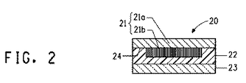
ここで図2を参照すると、太陽電池モジュール20は、それ自体、基板または表板21a上に被着させた薄膜太陽電池21bを含む太陽電池アセンブリ21を含む。基板または表板21aは、モジュールの最も外側の表面層である。一般に、薄膜太陽電池アセンブリ21は、太陽電池21bと接触しているアイオノマー封入材層22に対してラミネートされる。アイオノマー封入材層22は同様に、外部保護層23として役立つ薄いガラスシートに対してもラミネートされる。ここでもまた、薄膜太陽電池21bは、太陽電池モジュール20または基板または表板21aの側面積よりも小さい側面積を有する。こうして、封入材層22は基板または表板21aと接触し、それに結合して、太陽電池アセンブリ21bの縁部のまわりにシール24を形成してもよい。
Referring now to FIG. 2, the
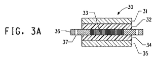
ここで図3Aおよび図3Bを参照すると、太陽電池モジュール30は、2つの封入材層32および34の間にラミネートされる太陽電池アセンブリ33を含む。これら3つの層は、それ自体2つの外部保護層31および35の間にラミネートされている。ここでもまた、2つの封入材層32および34の一方または両方がアイオノマー封入材層であり、2つの外部保護層31および35の一方または両方が薄いガラスシートであり、太陽電池アセンブリ33は、太陽電池モジュール30の側面積よりも小さい側面積を有する。その上、太陽電池モジュール30はさらに、2つの取付け用装置36を含み、その各々が、太陽電池モジュール30の相対する側に位置づけされてもよい。詳細には、各々の取付け用装置36は、太陽電池アセンブリ33の周縁部に隣接しその外側にある2つの封入材層32および34に結合された第1の部分36aおよび、太陽電池モジュール30の周縁部から外向きに突出している第2の部分36bを含む。
Referring now to FIGS. 3A and 3B, the
1つまたは複数の取付け用装置36を形成する上で任意の適切な材料を使用してもよい。より具体的には、取付け用装置36は、太陽電池モジュール30を支持する応力に耐えるのに充分なほどに耐久性のある任意の1つまたは複数の材料から製造されてもよい。さらに、取付け用装置36は、例えば風力、または建物の内部と外部の間の圧力差の力などの太陽電池モジュール30に対して加わるかもしれないあらゆる追加的力に耐えることもできなくてはならない。したがって、少なくとも1つの取付け用装置36は、鋼、アルミニウム、チタン、真鍮、鉛、クロム、銅またはこれらの金属の2つ以上の組合せまたは合金などの充分な強靭性を有する金属で作られていてもよい。あるいは、少なくとも1つの取付け用装置36は、充分な強靭性を有するプラスチック例えばポリカーボネート、ポリウレタン、ナイロンまたはこれらのプラスチックの2つ以上の組合せで作られていてもよい。
Any suitable material may be used in forming one or
図3Aおよび3Bをさらに参照すると、取付け用装置36bの第2の部分の中に含まれている固着用手段37が存在していてもよい。太陽電池モジュールを支持構造に固定するために使用可能なあらゆるタイプの固着用手段37をここで使用することができる。例えば図3Aおよび3Bに示されているように、固着用手段37は、支持構造上にモジュール30を固定するためのネジを収容するのに使用可能である取付け用装置36の第2の部分36b中の孔であってもよい。他の適切な固着用手段37としては、非限定的に、ネジに類似する手段例えば釘およびボルトが含まれる。孔を必要としない固着用手段37としては、取付け用装置36を介してフレームに対し太陽電池モジュール30をしっかりと固定するクランプまたは類似の装置が含まれる。クランプをフレームまたは取付け用装置36に対してしっかり固定してもよい。したがって、それはフレームを「挟持して」もよいし、あるいは取付け用装置36を「挟持して」もよい。
With further reference to FIGS. 3A and 3B, there may be an anchoring means 37 included in the second portion of the mounting
ここで図4を参照すると、太陽電池モジュール40は、図3Aおよび3B中に描かれている太陽電池モジュール30の構造と類似の構造を有する。それは2つの封入材層42および44、2つの外部保護層41および45、そして太陽電池アセンブリ43の周縁部に隣接しその外側にある2つの封入材層42および44に結合されている第1の部分46aと太陽電池モジュール40の周縁部から外向きに突出している第2の部分46bを含む取付け用装置46を含んでいる。ここでもまた、第2の部分46bには、取付け用装置46の第2の部分46bの中の孔として描かれている固着用手段47が具備されている。しかしながら、取付け用装置46はさらに、太陽電池モジュール40の周縁部全体にわたるカバーを形成する第3の部分46cを含む。
Referring now to FIG. 4, the
明らかに、四角形の太陽電池モジュール40の4つの縁部全てに沿って延在させた場合、4つの取付け用装置46は一種のフレームを形成すると考えられる。さらに、延在する取付け用装置46には複数の固着用手段47が具備されていてもよい。しかしながら、取付け用装置46がこの形態を有する必要はない。図3Aおよび3Bで描かれている取付け用装置36と同様に、図4で描かれている取付け用装置46は、太陽電池モジュール40の縁部の長さに比べて小さいサイズを有していてもよい。さらに、第3の部分46cは、取付け用装置46を突出させている部分に相当する周縁部の部分全体にわたるカバーを形成してもよい。あるいは、第3の部分46cは、取付け用装置46を突出させている部分よりも大きいかまたは小さい周縁部の部分全体にわたるカバーを形成してもよい。同様に明らかに、たとえ取付け用装置46が周縁部の長さに比べて小さい長さを有するとしても、周縁部全体にわたり4つのカバー部分46cが延在している取付け用装置46の形態によって第2のタイプのフレームが形成される。
Obviously, when extending along all four edges of the rectangular
ここで、図5を参照すると、太陽電池モジュール50は同様に、図3Aおよび3B中に描かれた太陽電池モジュール30の構造に類似した構造を有する。それは、太陽電池アセンブリおよび一方または両方が薄いガラスシートである少なくとも2枚のガラスシートの間にラミネートされた2つのアイオノマー封入材シートを含んでいる。しかしながら、太陽電池モジュール50は、二対の取付け用装置56を含む。各対の成員は、太陽電池モジュール50の相対する周縁部に付着されている。その上、取付け用装置56は同様に、アイオノマー封入材層に結合されている第1の部分56aおよび太陽電池モジュール50の周縁部から外向きに突出している第2の部分56bをも含んでいる。ここでもまた、第2の部分56bには、取付け用装置56の第2の部分56bの中の孔として描かれている固着用手段57が具備されている。図面には描かれていないが、取付け用装置56は、図4に示されている太陽電池モジュール40中の取付け用装置46の構造と類似する構造を有していてもよい。詳細には、これらには同様に、太陽電池モジュール50の周縁部全体にわたるカバーを形成する第3の部分が具備されていてもよい。
Referring now to FIG. 5, the
ここで図6を参照すると、太陽電池モジュール60は、図3Aおよび3Bの中で描かれている太陽電池モジュール30の構造に類似する構造を有する。それは、一方または両方が薄いガラスシートである少なくとも2つのガラスシートの間にラミネートされた少なくとも1つのアイオノマー封入材シートを含む。さらに、太陽電池モジュール60も同様に、二対の取付け用装置66を含むが、これらの取付け用装置は、図5に描かれている形態とは異なる形態で配置されている。太陽電池モジュール60においては、その4つの周縁部の各々に1つの取付け用装置66が付着される。他の取付け用装置36、46および56と同様に、取付け用装置66も、アイオノマー封入材に結合されている第1の部分66aと、太陽電池モジュール60の周縁部から外向きに突出する第2の部分66bを含む。ここでもまた第2の部分66bには、取付け用装置66の第2の部分66bの中の孔として描かれている固着用手段67が具備されている。最後に、図面には描かれていないが、取付け用装置66は、図4に示されている太陽電池モジュール40内の取付け用装置46の構造に類似した構造を有していてもよい。詳細には、これらには同様に、太陽電池モジュール60の周縁部全体にわたるカバーを形成する第3の部分が具備されていてもよい。
Referring now to FIG. 6, the
本明細書で使用される「太陽電池」という用語は、光を電気エネルギーに変換できるあらゆる物品を意味する。適切な太陽電池には、ウェハーベースの太陽電池(例えばc−Si、mc−Siおよびそれらの混合物から選択される材料を含む太陽電池)および薄膜太陽電池(例えばa−Si、μc−Si、CdTe、CIS、CIGS、光吸収性染料、有機半導体およびその混合物の中から選択された材料を含む太陽電池)が含まれるが、これらに限定されない。太陽電池アセンブリは、1つまたは複数の太陽電池を含んでいてもよい。複数の太陽電池を電気的に相互接続するかまたは平担な平面内に配置してもよい。太陽電池アセンブリはさらに、ウェハーベースの太陽電池においては導体ペースト、薄膜太陽電池においては導電性コーティング、またはいずれのタイプの太陽電池上でも被着される電気配線を含んでいてもよい。 As used herein, the term “solar cell” means any article capable of converting light into electrical energy. Suitable solar cells include wafer-based solar cells (eg, solar cells comprising materials selected from c-Si, mc-Si, and mixtures thereof) and thin film solar cells (eg, a-Si, μc-Si, CdTe). , CIS, CIGS, light-absorbing dyes, solar cells comprising materials selected from organic semiconductors and mixtures thereof). The solar cell assembly may include one or more solar cells. A plurality of solar cells may be electrically interconnected or arranged in a flat plane. The solar cell assembly may further include a conductive paste for wafer-based solar cells, a conductive coating for thin film solar cells, or electrical wiring deposited on any type of solar cell.
太陽電池アセンブリは、正面の太陽に対面する側および背面の太陽に対面しない側を有していてもよい。このような形態においては、光源と太陽電池アセンブリの正面の太陽に対面する側の間に位置づけされている全てのラミネートされた層は、光が太陽電池に到達できるように充分な透明度を有しているべきである。太陽電池アセンブリの背面の太陽に対面しない側の後ろに位置づけされたもう1つのラミネートされた層は、透明である必要はない。 The solar cell assembly may have a side facing the front sun and a side not facing the back sun. In such a configuration, all laminated layers positioned between the light source and the solar facing side of the front of the solar cell assembly have sufficient transparency so that light can reach the solar cell. Should be. Another laminated layer positioned behind the non-facing sun side of the back of the solar cell assembly need not be transparent.
あるいは、太陽電池層は両面受光型であってもよい。両面受光型太陽電池層を含む太陽電池モジュールにおいては、モジュール内に含まれる全てのラミネートされた層は、太陽電池アセンブリを除いて、光または反射光が太陽電池に到達できるように充分な透明度を有していなくてはならない。 Alternatively, the solar cell layer may be a double-sided light receiving type. In a solar cell module that includes a double-sided solar cell layer, all laminated layers contained within the module, except for the solar cell assembly, have sufficient transparency to allow light or reflected light to reach the solar cell. Must have.
本明細書中で使用される「薄いガラスシート」という用語は、2.0mm未満または約1.9mm以下または約1.8mm以下、または約1.7mm以下、または約1.6mm以下、または約1.5mm以下、または約1.2mm以下、または約1mm以下、または約0.8mm以下または約0.1〜約0.8mmまたは約0.2〜約0.7mm、または約0.2〜約0.6mmの厚みを有するガラスシートまたはフィルムを意味する。これらは、薄いブロックまたはロールドガラスシートなどの任意の適切なタイプのガラスシートから選択されてもよい。このような薄いガラスシートの一部のタイプは、液晶デバイス用基板として使用されてきており、例えばPraezisions Glas & Optik GmbH(Germany)、Pilkington(Toledo、OH)、松浪硝子工業株式会社(日本)、日本板硝子株式会社(日本)、日本電気硝子株式会社(日本)および旭硝子株式会社(日本)から市販されている。 As used herein, the term “thin glass sheet” refers to less than 2.0 mm, or less than about 1.9 mm, or less than about 1.8 mm, or less than about 1.7 mm, or less than about 1.6 mm, or about 1.5 mm or less, or about 1.2 mm or less, or about 1 mm or less, or about 0.8 mm or less, or about 0.1 to about 0.8 mm, or about 0.2 to about 0.7 mm, or about 0.2 to It means a glass sheet or film having a thickness of about 0.6 mm. These may be selected from any suitable type of glass sheet, such as a thin block or rolled glass sheet. Some types of such thin glass sheets have been used as substrates for liquid crystal devices, such as Praezions Glass & Optik GmbH (Germany), Pilkington (Toledo, OH), Matsunami Glass Industrial Co., Ltd. (Japan), Commercially available from Nippon Sheet Glass Co., Ltd. (Japan), Nippon Electric Glass Co., Ltd. (Japan), and Asahi Glass Co., Ltd. (Japan).
アイオノマー封入材シートは、2〜10個の炭素原子を有するα−オレフィンの共重合単位と、前駆体酸コポリマーの総重量に基づいて約18〜約30重量%または約20〜約25重量%または約21〜約24重量%の、3〜8個の炭素を有するα,β−エチレン性不飽和カルボン酸の共重合単位とを含む前駆体酸コポリマーのイオン中和誘導体であるアイオノマーを含んでいる。 The ionomer encapsulant sheet is about 18 to about 30 wt% or about 20 to about 25 wt% based on the total weight of alpha-olefin copolymerized units having 2 to 10 carbon atoms and the precursor acid copolymer or Containing an ionomer that is an ion neutralized derivative of a precursor acid copolymer containing from about 21 to about 24% by weight of a copolymerized unit of an α, β-ethylenically unsaturated carboxylic acid having 3 to 8 carbons .
適切なα−オレフィンコモノマーには、エチレン、プロピレン、1−ブテン、1−ペンテン、1−ヘキセン、1−ヘプテン、3 メチル−1−ブテン、4−メチル−1−ペンテンなど、およびそれらの2つ以上の混合物が含まれてもよいが、これらに限定されない。1つの好ましいコポリマーにおいて、α−オレフィンはエチレンである。 Suitable α-olefin comonomers include ethylene, propylene, 1-butene, 1-pentene, 1-hexene, 1-heptene, 3 methyl-1-butene, 4-methyl-1-pentene, and the like, and two of them. Although the above mixture may be contained, it is not limited to these. In one preferred copolymer, the α-olefin is ethylene.
適切なα,β−エチレン性不飽和カルボン酸コモノマーとしては、アクリル酸類、メタクリル酸類、イタコン酸類、マレイン酸類、マレイン酸無水物類、フマル酸類、モノメチルマレイン酸類およびそれらの2つ以上の混合物が含まれてもよいが、これらに限定されない。1つの好ましいコポリマーにおいて、α,β−エチレン性不飽和カルボン酸は、アクリル酸類、メタクリル酸類およびそれらの2つ以上の混合物から選択される。別の好ましいコポリマーにおいて、α,β−エチレン性不飽和カルボン酸はメタクリル酸である。 Suitable α, β-ethylenically unsaturated carboxylic acid comonomers include acrylic acid, methacrylic acid, itaconic acid, maleic acid, maleic anhydride, fumaric acid, monomethylmaleic acid and mixtures of two or more thereof However, it is not limited to these. In one preferred copolymer, the α, β-ethylenically unsaturated carboxylic acid is selected from acrylic acids, methacrylic acids, and mixtures of two or more thereof. In another preferred copolymer, the α, β-ethylenically unsaturated carboxylic acid is methacrylic acid.
前駆体酸コポリマーはさらに、1つ以上の他のコモノマーの共重合単位、例えば2〜10個または好ましくは3〜8個の炭素を有する不飽和カルボン酸またはその誘導体をさらに含んでいてもよい。適切な酸誘導体には、酸無水物、アミドおよびエステルが含まれる。エステルが好まれる。不飽和カルボン酸の好ましいエステルの具体的例としては、メチルアクリレート類、メチルメタクリレート類、エチルアクリレート類、エチルメタクリレート類、プロピルアクリレート類、プロピルメタクリレート類、イソプロピルアクリレート類、イソプロピルメタクリレート類、ブチルアクリレート類、ブチルメタクリレート類、イソブチルアクリレート類、イソブチルメタクリレート類、tert−ブチルアクリレート類、tert−ブチルメタクリレート類、オクチルアクリレート類、オクチルメタクリレート類、ウンデシルアクリレート類、ウンデシルメタクリレート類、オクタデシルアクリレート類、オクタデシルメタクリレート類、ドデシルアクリレート類、ドデシルメタクリレート類、2−エチルヘキシルアクリレート類、2−エチルヘキシルメタクリレート類、イソボルニルアクリレート類、イソボルニルメタクリレート類、ラウリルアクリレート類、ラウリルメタクリレート類、2−ヒドロキシエチルアクリレート類、2−ヒドロキシエチルメタクリレート類、グリシジルアクリレート類、グリシジルメタクリレート類、ポリ(エチレングリコール)アクリレート類、ポリ(エチレングリコール)メタクリレート類、ポリ(エチレングリコール)メチルエーテルアクリレート類、ポリ(エチレングリコール)メチルエーテルメタクリレート類、ポリ(エチレングリコール)べヘニルエーテルアクリレート類、ポリ(エチレングリコール)べヘニルエーテルメタクリレート類、ポリ(エチレングリコール)4−ノニルフェニルエーテルアクリレート類、ポリ(エチレングリコール)4−ノニルフェニルエーテルメタクリレート類、ポリ(エチレングリコール)フェニルエーテルアクリレート類、ポリ(エチレングリコール)フェニルエーテルメタクリレート類、ジメチルマレエート類、ジエチルマレエート類、ジブチルマレエート類、ジメチルフマレート類、ジエチルフマレート類、ジブチルフマレート類、ジメチルフマレート類、ビニルアセテート類、ビニルプロピオネート類およびそれらの2つ以上の混合物が含まれるが、これらに限定されない。1つの好ましいコポリマーにおいて、適切な追加のコモノマーは、メチルアクリレート類、メチルメタクリレート類、ブチルアクリレート類、ブチルメタクリレート類、グリシジルメタクリレート類、ビニルアセテート類およびそれら2つ以上の混合物から選択される。しかしながら別の好ましいコポリマーにおいて、前駆体酸コポリマーは他の追加のコモノマーを取込まない。 The precursor acid copolymer may further comprise an unsaturated carboxylic acid or derivative thereof having copolymerized units of one or more other comonomers, such as 2 to 10 or preferably 3 to 8 carbons. Suitable acid derivatives include acid anhydrides, amides and esters. Esters are preferred. Specific examples of preferred esters of unsaturated carboxylic acids include methyl acrylates, methyl methacrylates, ethyl acrylates, ethyl methacrylates, propyl acrylates, propyl methacrylates, isopropyl acrylates, isopropyl methacrylates, butyl acrylates, Butyl methacrylates, isobutyl acrylates, isobutyl methacrylates, tert-butyl acrylates, tert-butyl methacrylates, octyl acrylates, octyl methacrylates, undecyl acrylates, undecyl methacrylates, octadecyl acrylates, octadecyl methacrylates, Dodecyl acrylates, dodecyl methacrylates, 2-ethylhexyl acrylates, -Ethylhexyl methacrylates, isobornyl acrylates, isobornyl methacrylates, lauryl acrylates, lauryl methacrylates, 2-hydroxyethyl acrylates, 2-hydroxyethyl methacrylates, glycidyl acrylates, glycidyl methacrylates, poly (ethylene Glycol) acrylates, poly (ethylene glycol) methacrylates, poly (ethylene glycol) methyl ether acrylates, poly (ethylene glycol) methyl ether methacrylates, poly (ethylene glycol) behenyl ether acrylates, poly (ethylene glycol) bases Henyl ether methacrylates, poly (ethylene glycol) 4-nonylphenyl ether acrylates, poly (ethylene Lenglycol) 4-nonylphenyl ether methacrylates, poly (ethylene glycol) phenyl ether acrylates, poly (ethylene glycol) phenyl ether methacrylates, dimethyl maleates, diethyl maleates, dibutyl maleates, dimethyl fumarate , Diethyl fumarates, dibutyl fumarate, dimethyl fumarate, vinyl acetates, vinyl propionates, and mixtures of two or more thereof. In one preferred copolymer, suitable additional comonomers are selected from methyl acrylates, methyl methacrylates, butyl acrylates, butyl methacrylates, glycidyl methacrylates, vinyl acetates and mixtures of two or more thereof. However, in another preferred copolymer, the precursor acid copolymer does not incorporate other additional comonomers.
適切な前駆体酸コポリマーは、190℃、2.16kgでASTM方法D1238に準じて判定した場合に、約1〜約1000g/10分、または約20〜約900g/10分、または約20〜約70g/10分、または約70〜約700g/10分または約100〜約500g/10分または約150〜約300g/10分の溶融流量(MFR)を有する。 Suitable precursor acid copolymers are from about 1 to about 1000 g / 10 minutes, or from about 20 to about 900 g / 10 minutes, or from about 20 to about 20 when judged according to ASTM method D1238 at 190 ° C. and 2.16 kg. It has a melt flow rate (MFR) of 70 g / 10 min, or about 70 to about 700 g / 10 min, or about 100 to about 500 g / 10 min, or about 150 to about 300 g / 10 min.
最後に、適切な前駆体酸コポリマーを、例えば米国特許第3,404,134号明細書;5,028,674号明細書;6,500,888号明細書または6,518,365号明細書中に記載される通りに合成してもよい。 Finally, suitable precursor acid copolymers are described, for example, in US Pat. Nos. 3,404,134; 5,028,674; 6,500,888 or 6,518,365. You may synthesize as described in.
アイオノマー封入材シート中で有用なアイオノマーを得るためには、前駆体酸コポリマーは、1つ以上の塩基との反応により部分的に中和される。親酸コポリマーを中和するための適切な手順の一例は、米国特許第3,404,134号明細書および6,518,365号明細書中に記載されている。中和の後、前駆体酸中に存在するカルボン酸基の水素原子の約5%〜約90%、または約10%〜約60%、または約20%〜約55%が、他のカチオンによって置換される。換言すると、前駆体酸コポリマー中に存在するカルボン酸基の総含有量の約5%〜約90%または約10%〜約60%または約20%〜約55%が中和される。別の代替的表現をすると、酸性基は、非中和前駆体酸コポリマーについて計算または測定された通りの前駆体酸コポリマー中に存在するカルボン酸基の総含有量に基づいて、約5%〜約90%または約10%〜約60%または約20%〜約55%のレベルまで中和される。 To obtain useful ionomers in ionomer encapsulant sheets, the precursor acid copolymer is partially neutralized by reaction with one or more bases. An example of a suitable procedure for neutralizing the parent acid copolymer is described in US Pat. Nos. 3,404,134 and 6,518,365. After neutralization, about 5% to about 90%, or about 10% to about 60%, or about 20% to about 55% of the hydrogen atoms of the carboxylic acid groups present in the precursor acid are contributed by other cations. Replaced. In other words, about 5% to about 90% or about 10% to about 60% or about 20% to about 55% of the total content of carboxylic acid groups present in the precursor acid copolymer is neutralized. In another alternative expression, the acidic groups are from about 5% to about 5% based on the total content of carboxylic acid groups present in the precursor acid copolymer as calculated or measured for the non-neutralized precursor acid copolymer. Neutralized to a level of about 90% or about 10% to about 60% or about 20% to about 55%.
アイオノマーは、カルボキシレートアニオンに対する対イオンとして、カチオンを含む。適切なカチオンとしては、アイオノマー組成物が合成され、加工され使用される条件の下で安定している任意の正荷電種が含まれる。一部の好ましいアイオノマーにおいて、使用されるカチオンは、一価、二価、三価、多価またはその混合物であってもよい金属カチオンである。有用な一価の金属カチオンとしては、ナトリウム、カリウム、リチウム、銀、水銀、銅などのカチオンまたはそれらの混合物が含まれるが、これらに限定されない。有用な二価の金属カチオンとしては、ベリリウム、マグネシウム、カルシウム、ストロンチウム、バリウム、銅、カドミウム、水銀、錫、鉛、鉄、コバルト、ニッケル、亜鉛などのカチオンおよびそれらの混合物が含まれるが、これらに限定されない。有用な三価の金属カチオンとしては、アルミニウム、スカンジニウム、鉄、イットリウムなどのカチオンおよびそれらの混合物が含まれるが、これらに限定されない。有用な多価の金属カチオンとしては、チタン、ジルコニウム、ハフニウム、バナジウム、タンタル、タングスチン、クロム、セリウム、鉄などのカチオンおよびそれらの混合物が含まれるが、これらに限定されない。金属カチオンが多価である場合、米国特許第3,404,134号明細書中に記載されるように、ステアレート、オレエート、サリチレートおよびフェノレートラジカルなどの錯化剤を含み入れてもよいということが指摘される。別の好ましい封入材中では、使用される金属カチオンは一価または二価の金属カチオンである。さらに別の好ましい封入材において、金属カチオンは、ナトリウム、リチウム、マグネシウム、亜鉛、カリウムおよびそれらの混合物から選択される。さらに別の好ましい封入材において、金属カチオンは、ナトリウム、亜鉛およびそれらの混合物のカチオンから選択される。さらに別の封入材では、金属カチオンは、ナトリウムカチオンである。 The ionomer contains a cation as a counter ion for the carboxylate anion. Suitable cations include any positively charged species that is stable under the conditions under which the ionomer composition is synthesized, processed and used. In some preferred ionomers, the cations used are metal cations which may be monovalent, divalent, trivalent, multivalent or mixtures thereof. Useful monovalent metal cations include, but are not limited to, cations such as sodium, potassium, lithium, silver, mercury, copper, or mixtures thereof. Useful divalent metal cations include beryllium, magnesium, calcium, strontium, barium, copper, cadmium, mercury, tin, lead, iron, cobalt, nickel, zinc, and other cations and mixtures thereof. It is not limited to. Useful trivalent metal cations include, but are not limited to, cations such as aluminum, scandinium, iron, yttrium, and mixtures thereof. Useful polyvalent metal cations include, but are not limited to, cations such as titanium, zirconium, hafnium, vanadium, tantalum, tungsten, chromium, cerium, iron, and mixtures thereof. If the metal cation is multivalent, complexing agents such as stearate, oleate, salicylate and phenolate radicals may be included as described in US Pat. No. 3,404,134. It is pointed out. In another preferred encapsulant, the metal cation used is a monovalent or divalent metal cation. In yet another preferred encapsulant, the metal cation is selected from sodium, lithium, magnesium, zinc, potassium and mixtures thereof. In yet another preferred encapsulant, the metal cation is selected from cations of sodium, zinc and mixtures thereof. In yet another encapsulant, the metal cation is a sodium cation.
結果として得られるアイオノマーは、190℃、2.16kgでASTM方法D1238に準じて判定した場合に、25g/10分以下、または約20g/10分以下または約10g/10分以下、または約5g/10分以下または約0.7〜約5g/10分のMFRを有していてもよい。 The resulting ionomer is 25 g / 10 min or less, or about 20 g / 10 min or less, or about 10 g / 10 min or less, or about 5 g / min, as determined according to ASTM method D1238 at 190 ° C. and 2.16 kg. It may have an MFR of 10 minutes or less or about 0.7 to about 5 g / 10 minutes.
アイオノマー封入材シートはさらに、当該技術分野内で公知の他の添加剤を含んでいてもよい。添加剤には、加工助剤、流動促進添加剤、潤滑剤、顔料、染料、難燃剤、衝撃改質剤、核形成剤、ブロッキング防止剤例えばシリカ、熱安定剤、UV吸収剤、UV安定剤、分散剤、界面活性剤、キレート剤、カップリング剤、補強用添加剤例えばガラス繊維、充填剤などが含まれるが、これらに限定されない。適切な添加剤、アイオノマー封入材中の添加剤の適切なレベルおよびアイオノマー封入材中への添加剤の取込み方法についての一般的情報は、例えば「Kirk Othmer Encyclopedia、the Modern Plastics Encyclopedia」、McGraw−Hill(New York、1995)または「Wiley Encyclopedia of Packaging Technology」、2d edition、A.L.Brody and K.S.Marsh、Eds.、Wiley−Interscience(Hoboken、1997)などの参考文献中に見出されるかもしれない。アイオノマー封入材中で使用するためには、4つのタイプの添加剤、具体的には熱安定剤、UV吸収剤、ヒンダードアミン系光安定剤(HALS)およびシランカップリング剤に注目すべきである。これら4タイプの添加剤についてのさらなる情報、例えば、好ましい例およびアイオノマー封入材中の適切なレベルなどは、例えば以上で引用した参考文献中および米国特許第7,641,965号明細書中に見出されるかもしれない。 The ionomer encapsulant sheet may further include other additives known within the art. Additives include processing aids, flow promoting additives, lubricants, pigments, dyes, flame retardants, impact modifiers, nucleating agents, antiblocking agents such as silica, heat stabilizers, UV absorbers, UV stabilizers. , Dispersants, surfactants, chelating agents, coupling agents, reinforcing additives such as glass fibers, fillers and the like. General information on suitable additives, suitable levels of additives in ionomer encapsulants and how to incorporate the additives into ionomer encapsulants can be found in, for example, “Kirk Homer Encyclopedia, the Modern Plastics Encyclopedia”, McGraw-Hill. (New York, 1995) or “Wiley Encyclopedia of Packing Technology”, 2d edition, A.M. L. Brody and K.C. S. Marsh, Eds. , Wiley-Interscience (Hoboken, 1997). Of note are four types of additives for use in ionomer encapsulants, specifically heat stabilizers, UV absorbers, hindered amine light stabilizers (HALS), and silane coupling agents. Further information about these four types of additives, such as preferred examples and appropriate levels in ionomer encapsulants, can be found, for example, in the references cited above and in US Pat. No. 7,641,965. May be.
適切なアイオノマー封入材シートは、30℃、1分の負荷時間でASTM D5026に準じて判定された場合、約200〜約600MPa、または約250〜約550MPa、または約300〜約500MPa、または約300〜約400MPaのヤング率を有する。さらに、アイオノマー封入材シートは、約1〜約120ミル(約0.025〜約3mm)、または約5〜約100ミル(約0.127〜約2.54mm)、または約5〜約45ミル(約0.127〜約1.14mm)、または約10〜約35ミル(約0.25〜約0.89mm)、または約10〜約30ミル(約0.25〜約0.76mm)の合計厚みを有していてもよい。太陽電池モジュールが2つの以上のアイオノマー封入材シートを含む場合、各シートの厚みは独立して選択される。 Suitable ionomer encapsulant sheets are about 200 to about 600 MPa, or about 250 to about 550 MPa, or about 300 to about 500 MPa, or about 300, as determined according to ASTM D5026 at 30 ° C. and 1 minute loading time. Has a Young's modulus of about 400 MPa. Further, the ionomer encapsulant sheet may have a thickness of about 1 to about 120 mils (about 0.025 to about 3 mm), or about 5 to about 100 mils (about 0.127 to about 2.54 mm), or about 5 to about 45 mils. (About 0.127 to about 1.14 mm), or about 10 to about 35 mil (about 0.25 to about 0.89 mm), or about 10 to about 30 mil (about 0.25 to about 0.76 mm) You may have total thickness. When the solar cell module includes two or more ionomer encapsulant sheets, the thickness of each sheet is selected independently.
さらに、アイオノマーシートは、ラミネーションに先立ち一方または両方の側に平滑なまたは粗い表面を有していてもよい。1つの太陽電池モジュールにおいて、アイオノマーシートは、ラミネーションプロセス中の脱気を容易にするため両方の側に粗い表面を有していてもよい。粗い表面は、機械的エンボス加工によってかまたはシートの押出し加工中のメルトフラクチャとそれに続く急冷によって作り上げられ、こうして取扱い作業中も表面粗度が保持されるようになっている。表面パターンは、一般的な当該技術分野において認知されているプロセスを通してシートに適用可能である。例えば、溶融ポリマーの一方の側に所望される表面特性を付与するダイの出口に極近いところに位置づけされたダイロールの特別に前処理された表面の上に、押出し放しのシートを通過させてもよい。こうして、このようなダイロールの表面が微小な山や谷を有する場合、その上に流延されたポリマーシートは、ロールと接触している側に粗い表面を有し、粗い表面は一般にそれぞれロール表面の谷および山に一致する。このようなダイロールは、例えば米国特許第4,035,549号明細書および米国特許公開第20030124296号明細書中に記載されている。ここでもまたアイオノマーシートの表面パターンは、ラミネーションプロセス後に消失する。 Further, the ionomer sheet may have a smooth or rough surface on one or both sides prior to lamination. In one solar cell module, the ionomer sheet may have a rough surface on both sides to facilitate degassing during the lamination process. The rough surface is created by mechanical embossing or by melt fracture during sheet extrusion and subsequent quenching so that surface roughness is maintained during handling operations. The surface pattern can be applied to the sheet through processes recognized in the general art. For example, an extruded sheet may be passed over a specially pretreated surface of a die roll positioned very close to the die outlet that imparts the desired surface properties on one side of the molten polymer. Good. Thus, when the surface of such a die roll has minute peaks and valleys, the polymer sheet cast thereon has a rough surface on the side in contact with the roll, and the rough surface is generally a roll surface, respectively. Matches valleys and mountains. Such die rolls are described, for example, in US Pat. No. 4,035,549 and US Patent Publication No. 20030124296. Again, the surface pattern of the ionomer sheet disappears after the lamination process.
例えば、シートは、浸漬被覆、溶液流延、圧縮成形、射出成形、ラミネーション、溶融押出流延、インフレートフィルム、押出被覆、タンデム押出被覆または、当業者にとって公知である他の任意の手順を通して形成されてもよい。好ましくは、シートは、溶融押出流延、溶融同時押出流延、溶融押出被覆またはタンデム溶融押出被覆プロセスによって形成される。 For example, the sheet is formed through dip coating, solution casting, compression molding, injection molding, lamination, melt extrusion casting, blown film, extrusion coating, tandem extrusion coating, or any other procedure known to those skilled in the art. May be. Preferably, the sheet is formed by a melt extrusion casting, melt coextrusion casting, melt extrusion coating or tandem melt extrusion coating process.
太陽電池アセンブリの正面の太陽に対面する側にアイオノマー封入材層が位置づけされているこれらの太陽電池モジュールにおいては、封入材層は、モジュールの効率の良い動作を可能にするのに充分なほど透明でなくてはならない。適切な正面封入材層は好ましくは、ASTM D1003に準じて判定した場合に約1.5%以下または約1%以下の曇り度を有する。あるいは、適切なアイオノマー封入材層は、約1.5以下または約1以下の黄色度指数(YI)を有していてもよい。 In these solar cell modules, where the ionomer encapsulant layer is positioned on the front side of the solar cell assembly facing the sun, the encapsulant layer is transparent enough to allow efficient operation of the module. It must be. Suitable front encapsulant layers preferably have a haze of about 1.5% or less, or about 1% or less, as determined according to ASTM D1003. Alternatively, a suitable ionomer encapsulant layer may have a yellowness index (YI) of about 1.5 or less or about 1 or less.
1つ以上の太陽電池、1枚以上の薄いガラスシートおよび1枚以上のアイオノマー封入材シートに加えて、太陽電池モジュールはさらに追加のフィルム、剛性シートまたは他の非アイオノマーポリマー封入材シートを含んでいてもよい。 In addition to one or more solar cells, one or more thin glass sheets, and one or more ionomer encapsulant sheets, the solar cell module further includes additional films, rigid sheets, or other non-ionomer polymer encapsulant sheets. May be.
図1の12または14などの封入材層中で使用するための適切な非アイオノマー材料としては、限定的意味なく、エチレン性不飽和酸コポリマー、ポリ(エチレンビニルアセテート類)(EVA)、ポリ(ビニルアセタール類)(例えばポリ(ビニルブチラール類)(PVB))、ポリウレタン類、ポリ(ビニルクロリド類)、ポリエチレン類(例えば直鎖低密度ポリエチレン類)、ポリオレフィンブロックコポリマーエラストマー、α−オレフィンおよびα,β−エチレン性不飽和カルボン酸エステル類)のコポリマー(例えばエチレンメチルアクリレートコポリマーおよびエチレンブチルアクリレートコポリマー)、シリコーンエラストマー、エポキシ樹脂類、およびこれらの材料の2つ以上のブレンドまたは組合せが含まれる。 Suitable non-ionomer materials for use in encapsulant layers such as 12 or 14 of FIG. 1 include, without limitation, ethylenically unsaturated acid copolymers, poly (ethylene vinyl acetates) (EVA), poly ( Vinyl acetals) (eg poly (vinyl butyrals) (PVB)), polyurethanes, poly (vinyl chlorides), polyethylenes (eg linear low density polyethylenes), polyolefin block copolymer elastomers, α-olefins and α, [beta] -ethylenically unsaturated carboxylic acid esters) (eg, ethylene methyl acrylate copolymer and ethylene butyl acrylate copolymer), silicone elastomers, epoxy resins, and blends or combinations of two or more of these materials.
図1の11または15などの外部保護層の1つとして使用するのに適したシートまたはフィルムとしては、限定的な意味なく、従来のガラスシート、プラスチックシート、金属シート、セラミックシート、プラスチックフィルムおよび金属フィルムが含まれる。 Sheets or films suitable for use as one of the outer protective layers such as 11 or 15 in FIG. 1 include, without limitation, conventional glass sheets, plastic sheets, metal sheets, ceramic sheets, plastic films and Metal film is included.
適切な従来のガラスシートは、約2mm以上の厚みを有していてもよく、窓ガラス、厚ガラスシート、ケイ酸塩ガラス、並ガラスシート、低鉄ガラス、強化ガラス、無CeO強化ガラス、およびフロートガラスのみならず、色ガラス、特殊ガラス(例えば、太陽光加熱を制御するための成分を含むもの)、コーテッドガラス(例えば太陽光を制御する目的で金属(例えば銀またはインジウム錫酸化物)でのスパッタリングが施されたもの)、低Eガラス、Toroglas(登録商標)ガラス(Saint−Gobain N.A.Inc.(Trumbauersville、PA))、Solexia(商標)ガラス(PPG Industries(Pittsburgh、PA))やStarphire(登録商標)ガラス(PPG Industries)も含んでいる。 Suitable conventional glass sheets may have a thickness of about 2 mm or more, such as window glass, thick glass sheet, silicate glass, average glass sheet, low iron glass, tempered glass, CeO tempered glass, and Not only float glass, but also colored glass, special glass (for example, containing a component for controlling solar heating), and coated glass (for example, metal (for example, silver or indium tin oxide) for the purpose of controlling sunlight) ), Low-E glass, Toroglas® glass (Saint-Gobain NA Inc. (Trumbauersville, PA)), Solexia® glass (PPG Industries (Pittsburgh, PA)) And Starphire (registered trademark) glass (PPG ndustries) which also include a.
適切なプラスチックシートは、ポリカーボネート類、アクリル樹脂類、ポリアクリレート類、環式ポリオレフィン類(例えばエチレンノルボルネンポリマー)、ポリスチレン類(好ましくはメタロセン−触媒ポリスチレン類)、ポリアミド類、ポリエステル類、フルオロポリマーまたはこれらの材料の2つ以上の組合せなどの材料を含む。 Suitable plastic sheets are polycarbonates, acrylic resins, polyacrylates, cyclic polyolefins (eg ethylene norbornene polymers), polystyrenes (preferably metallocene-catalyzed polystyrenes), polyamides, polyesters, fluoropolymers or these Materials such as combinations of two or more of the above materials.
アルミニウム、鋼または亜鉛メッキ鋼またはセラミックプレートなどの不透明シートが使用される場合、それは、太陽電池アセンブリの後部の太陽に対面しない側に向かって位置づけされる背面保護層また背面シートの形で使用される。 When an opaque sheet such as aluminum, steel or galvanized steel or ceramic plate is used, it is used in the form of a back protection layer or back sheet that is positioned towards the back of the solar cell assembly facing the sun. The
適切なプラスチックフィルム層には、限定的な意味なく、ポリエステル類(例えばポリ(エチレンテレフタレート)およびポリ(エチレンナフタレート))、ポリカーボネート類、ポリオレフィン類(例えばポリプロピレン、ポリエチレン、および環式ポリオレフィン類)、ノルボルネンポリマー、ポリスチレン類(例えばシンジオタクチックポリスチレン)、スチレン−アクリレートコポリマー、アクリロニトリル−スチレンコポリマー、ポリスルホン類(例えばポリエーテルスルホン、ポリスルホンなど)、ナイロン類、ポリ(ウレタン類)、アクリル樹脂類、セルロースアセテート類(例えばセルロースアセテート、セルローストリアセテートなど)、セロファン類、ポリ(ビニルクロリド類)(例えばポリ(ビニリデンクロリド)、フルオロポリマー(例えばポリビニルフルオリド、ポリビニリデンフルオリド)、ポリテトラフルオロエチレン、エチレン−テトラフルオロエチレンコポリマーなど)およびそれらの2つ以上の組合せが含まれる。プラスチックフィルムは、2軸延伸ポリエステルフィルム(好ましくはポリ(エチレンテレフタレート)フィルム)またはフルオロポリマーフィルム(例えばE.I.du Pont de Nemours and Company(Wilmington、DE)(DuPont))製のTedlar(登録商標)、Tefzel(登録商標)およびTeflon(登録商標)フィルム)でもあってもよい。さらに本明細書中で使用されるフィルムは、多層フィルム、例えばフルオロポリマー/ポリエステル/フルオロポリマー多層フィルム(例えばIsovolta AG.(Austria)またはMadico(Woburn、MA)から入手可能なTedlar(登録商標)/PET/Tedlar(登録商標)またはTPTラミネートフィルム)の形をしていてもよい。 Suitable plastic film layers include, without limitation, polyesters (eg, poly (ethylene terephthalate) and poly (ethylene naphthalate)), polycarbonates, polyolefins (eg, polypropylene, polyethylene, and cyclic polyolefins), Norbornene polymers, polystyrenes (eg, syndiotactic polystyrene), styrene-acrylate copolymers, acrylonitrile-styrene copolymers, polysulfones (eg, polyethersulfone, polysulfone, etc.), nylons, poly (urethanes), acrylic resins, cellulose acetate (For example, cellulose acetate, cellulose triacetate, etc.), cellophanes, poly (vinyl chlorides) (for example, poly (vinylidene chloride), Ruoroporima (such as polyvinyl fluoride, polyvinylidene fluoride), polytetrafluoroethylene, ethylene - such as tetrafluoroethylene copolymer) and includes combinations of two or more thereof. The plastic film can be a biaxially stretched polyester film (preferably a poly (ethylene terephthalate) film) or a fluoropolymer film (e.g. EI du Pont de Nemours and Company (Wilmington, DE) (DuPont)) ), Tefzel (registered trademark) and Teflon (registered trademark) film). Further, as used herein, a film is a multilayer film, such as a fluoropolymer / polyester / fluoropolymer multilayer film (eg, Tedlar® / available from Isovolta AG. (Austria) or Madico (Woburn, Mass.)). PET / Tedlar® or TPT laminate film).
不透明フィルム、例えばアルミニウムホイルまたは充填ポリマーフィルムが使用される場合、それは、太陽電池アセンブリの後部の太陽に対面しない側に向かって位置づけされている背面保護層または背面シート内で使用される。 If an opaque film, such as an aluminum foil or filled polymer film, is used, it is used in a back protective layer or back sheet that is positioned towards the back of the solar cell assembly facing the sun.
太陽電池アセンブリが薄膜太陽電池を含む場合、太陽電池モジュールは同様に、この薄膜太陽電池を上に被着させる基板または表板をも含んでいる。適切な基板および表板は、薄いガラスシートを含め、外部保護層として上述したシートおよびフィルムである。適切な基板および表板は同様に、太陽電池および太陽電池アセンブリを製造し作動させる条件の下で安定している。 When the solar cell assembly includes a thin film solar cell, the solar cell module also includes a substrate or faceplate on which the thin film solar cell is deposited. Suitable substrates and faceplates are the sheets and films described above as the outer protective layer, including thin glass sheets. Appropriate substrates and faceplates are likewise stable under conditions that make and operate solar cells and solar cell assemblies.
太陽電池モジュールはさらに、モジュール内部に埋込まれた他の機能的フィルムまたはシート層を含んでいてもよい。このような機能層、例えば誘電体層または障壁層は、上述のポリマーフィルムのいずれを含んでいてもよく、またそのいずれから派生させてもよい。さらに、機能層は、追加の機能的コーティングで被覆されていてもよい。例えば米国特許第6,521,825号明細書および6,818,819号明細書および欧州特許第1182710号明細書中に記載されたものなどの金属酸化物コーティングで被覆されたポリ(エチレンテレフタレート)フィルムが、太陽電池モジュール内で酸素障壁および防湿層として機能するかもしれない。 The solar cell module may further include other functional film or sheet layers embedded within the module. Such functional layers, such as dielectric layers or barrier layers, may include any of the polymer films described above and may be derived from any of them. Furthermore, the functional layer may be coated with an additional functional coating. Poly (ethylene terephthalate) coated with a metal oxide coating such as those described, for example, in US Pat. Nos. 6,521,825 and 6,818,819 and EP 1182710 The film may function as an oxygen barrier and moisture barrier within the solar cell module.
所望される場合、太陽電池層と封入材の間に不織ガラス繊維(スクリム)層を含み入れて、ラミネーションプロセス中の脱気を容易にしかつ/または封入材のための補強材として役立たせてもよい。このようなスクリム層の使用については、米国特許第5,583,057号明細書;6,075,202号明細書;6,204,443号明細書;6,320,115号明細書および6,323,416号明細書および欧州特許第0769818号明細書中に記載されている。 If desired, a non-woven glass fiber (scrim) layer can be included between the solar cell layer and the encapsulant to facilitate degassing during the lamination process and / or serve as a reinforcement for the encapsulant. Also good. US Pat. Nos. 5,583,057; 6,075,202; 6,204,443; 6,320,115 and 6 for the use of such scrim layers. , 323,416 and European Patent No. 0769818.
所望される場合、保護層(すなわち正面および/または背面シート)、封入材層、および太陽電池モジュール内に取込まれた他の層の一方または両方の表面をラミネーションプロセスに先立って処理して、他のラミネート層への接着性を増強させてもよい。この接着性増強処理は、当該技術分野内で公知のあらゆる形態をとっていてもよく、火炎処理(例えば米国特許第2,632,921号明細書;2,648,097号明細書;2,683,894号明細書および2,704,382号明細書を参照)、プラズマ処理(例えば米国特許第4,732,814号明細書を参照)、電子ビーム処理、酸化処理、コロナ放電処理、化学処理、クロム酸処理、熱風処理、オゾン処理、紫外線処理、サンドブラスト処理、溶剤処理そしてそれらの2つ以上の組合せを含む。同様に、1つまたは複数のラミネート層の表面上の接着剤またはプライマーのコーティングをさらに適用することによって、接着強度をさらに改善させてもよい。例えば、米国特許第4,865,711号明細書は、一方または両方の表面上に被着された薄い炭素層を有する、結合能力が改善されたフィルムまたはシートについて記述している。他の例示的接着剤またはプライマーとしては、シラン、ポリ(アリルアミン)系プライマー(例えば米国特許第5,411,845号明細書;5,770,312号明細書;5,690,994号明細書および5,698,329号明細書を参照のこと)、およびアクリル系プライマー(例えば米国特許第5,415,942号明細書を参照のこと)が含まれてもよい。接着剤またはプライマーのコーティングは、単層の接着剤またはプライマーの形をとってもよく、約0.0004〜約1ミル(約0.00001〜約0.03mm)、または好ましくは約0.004〜約0.5ミル(約0.0001〜約0.013mm)、またより好ましくは約0.004〜約0.1ミル(約0.0001〜約0.003mm)の厚みを有していてもよい。 If desired, the surface of one or both of the protective layer (ie, front and / or back sheet), encapsulant layer, and other layers incorporated within the solar cell module may be treated prior to the lamination process, Adhesion to other laminate layers may be enhanced. This adhesion enhancing treatment may take any form known in the art, such as flame treatment (eg, US Pat. Nos. 2,632,921; 2,648,097; 2, 683,894 and 2,704,382), plasma treatment (see, for example, US Pat. No. 4,732,814), electron beam treatment, oxidation treatment, corona discharge treatment, chemistry Treatment, chromic acid treatment, hot air treatment, ozone treatment, ultraviolet treatment, sandblast treatment, solvent treatment and combinations of two or more thereof. Similarly, the adhesive strength may be further improved by further applying an adhesive or primer coating on the surface of one or more laminate layers. For example, U.S. Pat. No. 4,865,711 describes a film or sheet with improved bonding capability having a thin carbon layer deposited on one or both surfaces. Other exemplary adhesives or primers include silane, poly (allylamine) based primers (eg, US Pat. Nos. 5,411,845; 5,770,312; 5,690,994). And 5,698,329), and acrylic primers (see, eg, US Pat. No. 5,415,942). The adhesive or primer coating may take the form of a single layer adhesive or primer and is from about 0.0004 to about 1 mil (about 0.00001 to about 0.03 mm), or preferably from about 0.004 to about It may have a thickness of 0.5 mil (about 0.0001 to about 0.013 mm), and more preferably about 0.004 to about 0.1 mil (about 0.0001 to about 0.003 mm). .
さらに、ポリマーフィルムが太陽電池モジュールの外側表面層として取り込まれる場合、外側表面には、耐摩耗性ハードコートが具備されてもよい。耐摩耗性ハードコート内で使用するものとして公知の任意の材料を使用してもよい。例えば、ハードコートは、ポリシロキサン類または架橋(熱硬化性)ポリウレタン類を含んでいてもよい。同じく適しているのは、例えば、(A)イソシアネート含有オリゴマーとヒドロキシル含有オリゴマーとの反応または(B)エポキシド含有化合物と無水物含有オリゴマーの反応によって調製される、米国特許公開第2005/0077002号明細書中に記載されているものなどのオリゴマー系コーティングである。一部のモジュールにおいて、ハードコートは、米国特許第4,177,315号明細書;4,469,743号明細書;5,415,942号明細書および5,763,089号明細書中に記述されているものなどのポリシロキサン耐摩耗性コーティングを含んでいてもよい。 Furthermore, when the polymer film is incorporated as an outer surface layer of the solar cell module, the outer surface may be provided with an abrasion-resistant hard coat. Any material known for use in an abrasion resistant hard coat may be used. For example, the hard coat may include polysiloxanes or cross-linked (thermosetting) polyurethanes. Also suitable are, for example, US 2005/0077002 prepared by reaction of (A) an isocyanate-containing oligomer with a hydroxyl-containing oligomer or (B) a reaction of an epoxide-containing compound with an anhydride-containing oligomer. Oligomer-based coatings such as those described in the book. In some modules, the hard coat is incorporated in US Pat. Nos. 4,177,315; 4,469,743; 5,415,942 and 5,763,089. It may include a polysiloxane abrasion resistant coating such as those described.
太陽電池モジュールを調製するためには、任意の適切なラミネーションプロセスを使用してもよい。1つの適切なプロセスにおいて、シート形態の太陽電池モジュールの構成要素層は、所望の順序で積重ねられてプリラミネーションアセンブリを形成する。アセンブリは次に、真空を維持できるバッグ(真空バッグ)内に入れられ、真空ラインまたは他の手段によってバッグから空気が吸引される。このバッグは、真空(例えばHgで少なくとも約27〜28(689〜711mmHg))が維持されている間に密封され、密封したバッグはオートクレーブ内に置かれ、約10〜約50分、または約20〜約45分、または約20〜約40分または約25〜約35分間、約130℃〜約180℃、または約120℃〜約160℃、または約135℃〜約155℃、または約145℃〜約155℃の温度で、圧力は、約150〜約250psi(約11.3〜約18.8バール)まで上昇させられる。真空バッグの代りに真空リングを用いてもよい。適切な真空バッグの1つのタイプは、米国特許第3,311,517号明細書中に記載されている。熱および圧力サイクルの後、オートクレーブ内の空気は、オートクレーブ内の圧力を維持するため追加の気体を加えることなく冷却される。約20分間の冷却後、余剰の空気圧力は放出されラミネートはオートクレーブから取り出される。 Any suitable lamination process may be used to prepare the solar cell module. In one suitable process, the component layers of a sheet form solar cell module are stacked in the desired order to form a pre-lamination assembly. The assembly is then placed in a bag that can maintain a vacuum (vacuum bag) and air is drawn from the bag by a vacuum line or other means. The bag is sealed while a vacuum (eg, at least about 27-28 (689-711 mmHg) in Hg) is maintained, and the sealed bag is placed in an autoclave for about 10 to about 50 minutes, or about 20 To about 45 minutes, or about 20 to about 40 minutes or about 25 to about 35 minutes, about 130 ° C to about 180 ° C, or about 120 ° C to about 160 ° C, or about 135 ° C to about 155 ° C, or about 145 ° C. At a temperature of about ˜155 ° C., the pressure is raised to about 150 to about 250 psi (about 11.3 to about 18.8 bar). A vacuum ring may be used instead of the vacuum bag. One type of suitable vacuum bag is described in US Pat. No. 3,311,517. After the heat and pressure cycle, the air in the autoclave is cooled without adding additional gas to maintain the pressure in the autoclave. After cooling for about 20 minutes, excess air pressure is released and the laminate is removed from the autoclave.
あるいは、プリラミネーションアセンブリをオーブン内で約80℃〜約120℃または約90℃〜約100℃で、約20〜約40分間加熱し、その後加熱したアセンブリを一組のニップロールに通して、個々の層間のすき間から空気を絞り出し、アセンブリの縁部を密封し得るようにしてもよい。この段階におけるアセンブリは、プリプレスと呼ばれる。 Alternatively, the pre-lamination assembly is heated in an oven at about 80 ° C. to about 120 ° C. or about 90 ° C. to about 100 ° C. for about 20 to about 40 minutes, after which the heated assembly is passed through a set of nip rolls to provide individual Air may be squeezed out of the gaps between the layers so that the edges of the assembly can be sealed. The assembly at this stage is called prepress.
次に、プリプレスをエアーオートクレーブ内に入れてもよく、ここで、約100〜約300psi(約6.9〜約20.7バール)または好ましくは約200psi(13.8バール)の圧力で約120℃〜約160℃、または約135℃〜約160℃まで温度は上昇させる。これらの条件は、約15〜約60分間または約20〜約50分間維持され、その後空気は冷却され、その間オートクレーブにさらなる空気は全く導入されない。約20分〜約40分の冷却後、余剰の空気圧は放出され、ラミネートされた製品は、オートクレーブから取出される。 The prepress may then be placed in an air autoclave where it is about 120 at a pressure of about 100 to about 300 psi (about 6.9 to about 20.7 bar) or preferably about 200 psi (13.8 bar). The temperature is raised from 0C to about 160C or from about 135C to about 160C. These conditions are maintained for about 15 to about 60 minutes or about 20 to about 50 minutes, after which the air is cooled while no further air is introduced into the autoclave. After cooling for about 20 minutes to about 40 minutes, excess air pressure is released and the laminated product is removed from the autoclave.
太陽電池モジュールを、非オートクレーブプロセスを通して生産してもよい。適切な非オートクレーブプロセスは、例えば米国特許第3,234,062号明細書;3,852,136号明細書;4,341,576号明細書;4,385,951号明細書;4,398,979号明細書;5,536,347号明細書;5,853,516号明細書;6,342,116号明細書および5,415,909号明細書、米国特許公開第20040182493号明細書、欧州特許第1235683B1号明細書およびPCT国際公開第9101880号パンフレットおよび国際公開第03057478号パンフレット中に記載されている。一般に、非オートクレーブプロセスは、プリラミネーションアセンブリの加熱ステップおよび真空、圧力またはその両方の適用ステップを含む。例えば、アセンブリを加熱用オーブンとニップロールに連続して通してもよい。 Solar cell modules may be produced through a non-autoclave process. Suitable non-autoclave processes are described, for example, in US Pat. Nos. 3,234,062; 3,852,136; 4,341,576; 4,385,951; 4,398. No. 5,979; No. 5,536,347; No. 5,853,516; No. 6,342,116 and No. 5,415,909; US Patent Publication No. 20040182493 European Patent No. 1235683B1, PCT International Publication No. 9101880 pamphlet and International Publication No. 03057478. In general, a non-autoclave process includes a pre-lamination assembly heating step and a vacuum, pressure or both application step. For example, the assembly may be continuously passed through a heating oven and nip roll.
これに関連して、封入材シートは一般に、実質的に均一な厚みを有するシートとして供給される。封入材シートが、プリプレスアセンブリ内で太陽電池アセンブリと共にレイアップされる場合、太陽電池アセンブリの複数の部分が封入材シートと接触していないギャップまたは空隙が存在するかもしれない。しかしながら、ラミネーションプロセス中、ポリマー封入材シートは或る程度まで溶融または軟化する。プロセス中に加えられる圧力の下で封入材も同様に太陽電池アセンブリの表面の山部または輪郭のまわりを流動する。したがって、太陽電池アセンブリと封入材シートの間のあらゆる空隙はラミネーションプロセス中に充填されて、封入材が太陽電池アセンブリと良好な接触状態にある太陽電池モジュールが得られる。 In this connection, the encapsulant sheet is generally supplied as a sheet having a substantially uniform thickness. If the encapsulant sheet is laid up with the solar cell assembly in the prepress assembly, there may be gaps or voids where multiple portions of the solar cell assembly are not in contact with the encapsulant sheet. However, during the lamination process, the polymer encapsulant sheet melts or softens to some extent. Under pressure applied during the process, the encapsulant also flows around the peaks or contours of the surface of the solar cell assembly. Thus, any air gap between the solar cell assembly and the encapsulant sheet is filled during the lamination process, resulting in a solar cell module in which the encapsulant is in good contact with the solar cell assembly.
所望される場合、ラミネートされた太陽電池モジュールの縁部は、水分および空気の進入と太陽電池の効率および寿命に対する潜在的な劣化作用を削減するために密封されてもよい。適切な縁部シール材料としては、ブチルゴム、ポリスルフィド、シリコーン、ポリウレタン、ポリプロピレンエラストマー、ポリスチレンエラストマー、ブロックエラストマー、スチレン−エチレン−ブチレン−スチレン(SEBS)などが含まれるが、これらに限定されない。 If desired, the edges of the laminated solar cell module may be sealed to reduce moisture and air ingress and potential degradation effects on solar cell efficiency and lifetime. Suitable edge seal materials include, but are not limited to, butyl rubber, polysulfide, silicone, polyurethane, polypropylene elastomer, polystyrene elastomer, block elastomer, styrene-ethylene-butylene-styrene (SEBS), and the like.
以下の実施例は、本発明をさらに詳細に説明する目的で提供される。本発明を実施するために現在企図されている好ましい態様を説明するこれらの実施例は、本発明を例示するように意図されたものであって、それを限定するように意図されたものではない。 The following examples are provided for the purpose of further illustrating the present invention. These examples illustrating preferred embodiments presently contemplated for practicing the present invention are intended to be illustrative of the present invention and are not intended to be limiting. .
以下の実施例の各々において、同一の2セットのガラスラミネートが調製されており、1つのセットはラミネーション直後に、衝撃接着試験、含水量試験および応力試験に付され、もう1つのセットは、IEC61646にしたがって温度を−40℃と85℃の間で交番させる50回の熱サイクルを受けた後、衝撃接着、含水量および応力試験に付された。 In each of the following examples, two identical sets of glass laminates were prepared, one set was subjected to impact adhesion testing, moisture content testing and stress testing immediately after lamination, and the other set was IEC 61646. Were subjected to impact bonding, moisture content and stress testing after being subjected to 50 thermal cycles alternating between -40 ° C and 85 ° C.
実施例E1において調製されたガラスラミネートの各々は、15×15cmの寸法および「ガラスシート1/アイオノマー中間層シート/ガラスシート2」という重層構造を有し、ここで「ガラスシート1」は、PPG Industries、Pittsburgh、PA製の厚み2.3mmのガラスシートであり;「ガラスシート2」は、Euro−Tech GmbH(Germany)製の厚み0.7mmのガラスシートであり;「アイオノマー中間層シート」はE.I.DuPont de Nemours & Co.(Wilmington、DE)(以下「DuPont」と呼ぶ)から入手可能な厚み35ミル(0.89mm)のDuPontPV5300アイオノマー樹脂封入材シートである。実施例E2で調製されるガラスラミネートは、ラミネートの相対する側面に沿ってかつそれぞれの縁部から約2cm離して「ガラスシート1」と「アイオノマー中間層シート」の間にさらに長さ20cm、幅2mmおよび厚み100μmのワイヤー対が埋込まれているという点を除いて、実施例E1で調製されるものと類似している。実施例E3で調製されるガラスラミネートは、長さ20cm、幅2mm、厚み100μmの2本のワイヤーの各々が、ラミネートから突出する片端を有するという点を除いて、実施例E2で調製されるものと類似している。
Each of the glass laminates prepared in Example E1 has a dimension of 15 × 15 cm and a multilayer structure of “glass sheet 1 / ionomer interlayer sheet / glass sheet 2”, where “glass sheet 1” is PPG A 2.3 mm thick glass sheet manufactured by Industries, Pittsburgh, PA; “Glass Sheet 2” is a 0.7 mm thick glass sheet manufactured by Euro-Tech GmbH (Germany); “Ionomeric interlayer sheet” is E. I. DuPont de Nemours & Co. A DuPont PV5300 ionomer resin encapsulant sheet having a thickness of 35 mil (0.89 mm) available from (Wilmington, DE) (hereinafter referred to as “DuPont”). The glass laminate prepared in Example E2 is further 20 cm in length and width between “Glass Sheet 1” and “Ionomer Intermediate Sheet” along opposite sides of the laminate and about 2 cm from each edge. Similar to that prepared in Example E1, except that a 2 mm and 100 μm thick wire pair is embedded. The glass laminate prepared in Example E3 is prepared in Example E2 except that each of the two
「ガラスシート1/使用される場合にはワイヤー/アイオノマー中間層シート/ガラスシート2」アセンブリを使い捨ての真空バッグ内に置くこと、室温で約20分間真空バッグ内部においてアセンブリを真空下に維持すること、アセンブリを収納する真空バッグを、90℃に設定したオーブン内にさらに20分間置くこと、真空バッグからアセンブリを取り出すこと、そして最後にアセンブリを、20分間145℃の最高温度と8.5バールの最大プラトー圧を提供する条件下で行なわれたオートクレーブプロセスに付すことによって、ガラスラミネートE1、E2およびE3の各々を調製した。 Place the “Glass Sheet 1 / Wire / Ionomer Intermediate Sheet / Glass Sheet 2” assembly in a disposable vacuum bag, if used, and keep the assembly under vacuum for about 20 minutes at room temperature Place the vacuum bag containing the assembly in an oven set at 90 ° C. for an additional 20 minutes, remove the assembly from the vacuum bag, and finally place the assembly at a maximum temperature of 145 ° C. and 8.5 bar for 20 minutes. Each of the glass laminates E1, E2 and E3 was prepared by subjecting it to an autoclave process performed under conditions that provide maximum plateau pressure.
各ラミネートの衝撃接着値を、最初に25℃+/−5℃で1時間以上の間試料を平衡化し、次に0.5kgの平頭ハンマー(flat headed hammer)でラミネートを打撃することによって判定した。衝撃場所間の間隔1.25cmそして横列間間隔2cmで、横列パターンでラミネートを打撃した。表1に示された任意の尺度にしたがって、中間層に接着した状態にとどまっている粉砕ガラスの量に基づいて、衝撃接着評定を割当てた。 The impact adhesion value of each laminate was determined by first equilibrating the sample for at least 1 hour at 25 ° C. + / − 5 ° C. and then striking the laminate with a 0.5 kg flat headed hammer. . The laminate was struck in a row pattern with a spacing of 1.25 cm between impact locations and a 2 cm spacing between rows. An impact adhesion rating was assigned based on the amount of ground glass that remained adhered to the interlayer, according to any scale shown in Table 1.

各ラミネートについて2つの衝撃接着値を測定し、「IN」値は、「ガラスシート1」上でラミネートをハンマー打撃することにより決定され、「OUT」値は「ガラスシート2」上でラミネートをハンマー打撃することで判定された。 Two impact adhesion values are measured for each laminate and the “IN” value is determined by hammering the laminate on “Glass Sheet 1” and the “OUT” value is hammered on “Glass Sheet 2”. Judged by hitting.
Perkin Elmer(Waltham,MA)製のSpectrum BX FTIRスペクトロメーターを用いて、各ラミネートの水分増加レベルを判定した。具体的には、透過近赤外線(NIR)スペクトルを記録し、1880nmと1990nmの間の水分バンドを積分した。次に、積分した面積を水分基準に比較して試料中の含水率を計算した。各ラミネートについて、2つの位置で、水分利得値を記録した。「位置1」は、ラミネートの縁部から約1cm離れた場所であり、「位置2」はラミネートの中心に近い場所であった。実施例E2およびE3において、位置1は縁部とワイヤーの間にあった。 The moisture increase level of each laminate was determined using a Spectrum BX FTIR spectrometer manufactured by Perkin Elmer (Waltham, Mass.). Specifically, a transmitted near infrared (NIR) spectrum was recorded and a moisture band between 1880 nm and 1990 nm was integrated. Next, the moisture content in the sample was calculated by comparing the integrated area with the moisture standard. For each laminate, moisture gain values were recorded at two locations. “Position 1” was about 1 cm away from the edge of the laminate, and “Position 2” was near the center of the laminate. In Examples E2 and E3, position 1 was between the edge and the wire.
各ラミネート上で発生した応力を、180〜90度の間で変動する角度で交差分極光の下で観察することにより目視で判定した。応力を表わす虹様の特徴は、試料ラミネート中に全く観察されなかった。 The stress generated on each laminate was determined visually by observing under cross-polarized light at an angle varying between 180-90 degrees. No rainbow-like features representing stress were observed in the sample laminate.
表2に示されているデータは、厚み0.7mmの薄いガラスシートと35ミル(0.89mm)のアイオノマー中間層シートを用いたガラスラミネートが、良好な衝撃接着レベル、良好な耐湿性そして低い応力を有することを示している。このことは、アイオノマー中間層を有するガラスラミネート内の外部保護層の一方または両方として薄いガラスシートを使用することが実現可能であり、こうして、その物理的強度を維持しながらラミネートの重量が削減される、ということを実証している。 The data shown in Table 2 shows that a glass laminate using a thin glass sheet of 0.7 mm thickness and a 35 mil (0.89 mm) ionomer interlayer sheet has good impact adhesion levels, good moisture resistance and low It shows that it has stress. This makes it feasible to use a thin glass sheet as one or both of the outer protective layers in a glass laminate with an ionomer interlayer, thus reducing the weight of the laminate while maintaining its physical strength. It is proved that.
比較例C1および実施例E4およびE5
以下の仮説的グレージング構築物における応力発生およびたわみは、非線形有限要素モデリング(FEM)応力解析により計算する。例C1では、グレージング構築物は、厚み6.5mmのポリカーボネートシートである。実施例E4では、グレージング構築物は、2枚の薄いガラスシート(厚み1mm)の間にDuPont社から入手可能な1枚のDuPontPV5300アイオノマー封入材シート(厚み4.56mm)がラミネートされたラミネートである。実施例E5では、グレージング構築物は、2枚の薄いガラスシート(厚み1mm)の間に1枚のDuPontPV5300アイオノマー封入材シート(厚み3.04mm)がラミネートされたラミネートである。これらの例の各々においてグレージング構築物は1000×800mmの寸法を有し、4側面上で支持されている。2kPaの均一負荷が加えられる。グレージング構築物の各構成要素についてヤング率およびポワソン比を表3に列記する。
Comparative Example C1 and Examples E4 and E5
Stress generation and deflection in the following hypothetical glazing construct is calculated by nonlinear finite element modeling (FEM) stress analysis. In Example C1, the glazing construct is a 6.5 mm thick polycarbonate sheet. In Example E4, the glazing construct is a laminate in which a sheet of DuPont PV5300 ionomer encapsulant (4.56 mm thick) available from DuPont is laminated between two thin glass sheets (1 mm thick). In Example E5, the glazing construct is a laminate in which one DuPont PV5300 ionomer encapsulant sheet (thickness 3.04 mm) is laminated between two thin glass sheets (thickness 1 mm). In each of these examples, the glazing construct has a size of 1000 × 800 mm and is supported on four sides. A uniform load of 2 kPa is applied. The Young's modulus and Poisson's ratio for each component of the glazing construct are listed in Table 3.
a.ENISO1288にしたがって測定。
b.EN843にしたがって測定。
c.40℃、1日の負荷時間でASTM D5026にしたがって測定。
d.30℃、1分の負荷時間でASTM D5026にしたがって測定。
e.ISO527にしたがって測定。
a. Measured according to ENISO 1288.
b. Measured according to EN843.
c. Measured according to ASTM D5026 at 40 ° C. and 1 day loading time.
d. Measured according to ASTM D5026 at 30 ° C. with 1 minute loading time.
e. Measured according to ISO 527.
各ラミネートの最大応力発生およびたわみは、SJ−MEPLA(ドイツ、SJ−Softwareのバージョン3.0.4)を用いて計算する。結果として得た値を表4で報告する。 The maximum stress generation and deflection of each laminate is calculated using SJ-MEPLA (Germany, version 3.0.4 of SJ-Software). The resulting values are reported in Table 4.
これらの結果は、薄い(1mm)ガラスシートおよびアイオノマー中間層を伴うラミネートが、ポリカーボネートシートに比較した場合により高い強度を有しより低いたわみを示すということを実証している。 These results demonstrate that laminates with thin (1 mm) glass sheets and ionomer interlayers have higher strength and lower deflection when compared to polycarbonate sheets.
実施例E6
「薄いガラスシート(1.1mm)/アイオノマーシート(60ミル)/薄いガラスシート(1.1mm)」の構造をもつ一連のラミネートを調製した。薄いガラスシートは、日本板硝子株式会社(日本国、東京)より入手したUFF(商標)薄ガラスであり、アイオノマーシートは、DuPont社から入手したPV5300シートであった。
Example E6
A series of laminates having the structure "thin glass sheet (1.1 mm) / ionomer sheet (60 mil) / thin glass sheet (1.1 mm)" were prepared. The thin glass sheet was UFF (trademark) thin glass obtained from Nippon Sheet Glass Co., Ltd. (Tokyo, Japan), and the ionomer sheet was a PV5300 sheet obtained from DuPont.
次にラミネートを、数回の欧州安全基準試験に付した。EN356−P2A試験においては、鋼球(直径100mm、重量4.11kg)を3mの高さから3回、ラミネート構造上に落下させた。ラミネートは、3回目の衝撃の後も貫通されなかったことから、この試験に合格した。EN356−P3A試験においては、鋼球(直径100mm、重量4.11kg)を6mの高さから3回、ラミネート構造上に落下させた。鋼球は3回目の落下でラミネートを貫通したことから、第1のラミネートは不合格となったが、第2のラミネートは、3回目の落下後も貫通しなかったために合格した。最後に、EN356−P4A試験においては、鋼球(直径100mmおよび重量4.11kg)を高さ9mから3回、ラミネート構造上に落下させた。鋼球は、2回目の落下でラミネートを貫通したことから、ラミネートはこの試験に不合格となった。 The laminate was then subjected to several European safety standard tests. In the EN356-P2A test, a steel ball (diameter 100 mm, weight 4.11 kg) was dropped on the laminate structure three times from a height of 3 m. The laminate passed this test because the laminate was not penetrated after the third impact. In the EN356-P3A test, a steel ball (diameter 100 mm, weight 4.11 kg) was dropped three times from a height of 6 m onto the laminate structure. Since the steel ball penetrated the laminate in the third drop, the first laminate failed, but the second laminate passed because it did not penetrate after the third drop. Finally, in the EN356-P4A test, a steel ball (diameter 100 mm and weight 4.11 kg) was dropped on the laminate structure three times from a height of 9 m. Since the steel ball penetrated the laminate on the second drop, the laminate failed this test.
実施例E7〜E14
以上で使用したものと類似のラミネーションプロセスにより、一連の「ガラス1/アイオノマー中間層/ガラス2」のラミネートを調製した。これらのラミネートの構造は、表5に示されている。ラミネートをJISR3205ボール落下試験に付し、この試験では、直径63mm、重量1.04kgの鋼球を最初に120cmの高さから610×610mmという寸法のラミネート上に落下させた。破壊が全く起こらなかった場合、150cmの高さ、次に190cm、次に240cm、次に300cm、次に380cm、そして次に480cmの高さから落下をくり返した。この実験の結果も同様に表5中に記録する。
Examples E7-E14
A series of “glass 1 / ionomer interlayer / glass 2” laminates were prepared by a lamination process similar to that used above. The structure of these laminates is shown in Table 5. The laminate was subjected to a JIS R 3205 ball drop test, in which a steel ball having a diameter of 63 mm and a weight of 1.04 kg was first dropped from a height of 120 cm onto a laminate measuring 610 × 610 mm. If no fracture occurred, the fall was repeated from a height of 150 cm, then 190 cm, then 240 cm, then 300 cm, then 380 cm, and then 480 cm. The results of this experiment are also recorded in Table 5.
b.アイオノマー中間層シートはDuPontから入手したPV5300シートであった。
b. The ionomer interlayer sheet was a PV5300 sheet obtained from DuPont.
実施例E15およびE16
実施例E15では、アイオノマー中間層を伴うガラスラミネートを調製する。ラミネートを72カ月間、フロリダにおいて屋外での自然風化作用に曝露し、かつ96カ月の等価曝露としてアリゾナでの屋外促進風化作用に曝露する。風化作用の後、ラミネート中にはいかなる層間剥離、目視による欠陥、縁部曇り、または望ましくない曇り度の変化も観察されていない。その上、ラミネートの引張り強度は、4500時間の実験室内促進風化作用の後も、高いままである。
Examples E15 and E16
In Example E15, a glass laminate with an ionomer interlayer is prepared. The laminate is exposed to outdoor natural weathering in Florida for 72 months and exposed to outdoor accelerated weathering in Arizona as an equivalent exposure of 96 months. After weathering, no delamination, visual defects, edge haze, or undesirable haze changes are observed in the laminate. Moreover, the tensile strength of the laminate remains high after 4500 hours of laboratory accelerated weathering.
実施例E16では、アイオノマー中間層またはPVB中間層を伴うガラスラミネートを調製する。結露凍結試験の後、アイオノマー中間層を伴うこれらのラミネートには、いかなる目視による欠陥も、層間剥離も、変色も接着喪失も見られない。しかしながら、PVB中間層を伴うラミネートにおいては、結露凍結試験の後、縁部曇りおよび層間剥離の両方が観察される。 In Example E16, a glass laminate with an ionomer interlayer or PVB interlayer is prepared. After the condensation freeze test, these laminates with an ionomer interlayer do not show any visual defects, delamination, discoloration or loss of adhesion. However, in laminates with a PVB interlayer, both edge haze and delamination are observed after the condensation freeze test.
実施例E17
2つのガラス板(厚み3.2mm)の間にラミネートされたEVA中間層、PVB中間層およびアイオノマー中間層の水分進入プロファイルは、FTIR方法を用いてならびにASTM D7191の方法を用いて、Kapurらが獲得した。Kapurら、「Proceedings of the Photovoltaic Specialists Conference (PVSC)」、2009 34th IEEE; Digital Object Identifier:10.1109/PVSC.2009.5411235;刊行年:2009年、頁数:001210−001214を参照のこと。Kapurらが得たデータは、アイオノマー中間層内への水分進入が、EVAおよびPVB中間層内への水分進入よりも少ないことを実証している。ガラスラミネート内への水分進入は、厚みが少なくとも約0.1mmである場合には、ガラス層の厚みによる有意な影響を受けないとも考えられている。したがって、2枚の薄いガラスシート間のアイオノマー中間層のラミネートが、Kapurらにより研究されたPVBラミネートの水分進入よりも低い、すなわちそれよりも優れた水分進入を有することが予測される。
Example E17
The moisture ingress profiles of EVA, PVB and ionomer interlayers laminated between two glass plates (thickness 3.2 mm) were determined by Kapur et al. Using the FTIR method and using the method of ASTM D7191. Won. Kapur et al., "Proceedings of the Photovoltaic Specialties Conference (PVSC)", 2009 34th IEEE; Digital Object Identifier: 10.10109 / PVSC. 2009.5411235; publication year: 2009, pages: 001210-001214. The data obtained by Kapur et al. Demonstrates that there is less moisture ingress into the ionomer interlayer than into EVA and PVB interlayers. It is also believed that moisture ingress into the glass laminate is not significantly affected by the thickness of the glass layer if the thickness is at least about 0.1 mm. Thus, it is expected that the laminate of the ionomer interlayer between two thin glass sheets will have a moisture penetration that is lower than, or superior to, that of the PVB laminate studied by Kapur et al.
本発明の好ましい実施形態のいくつかを以上で記述し具体的に例証してきたが、本発明がこのような実施形態に限定されることは意図されていない。さらに、本発明の構造および機能の詳細と共に、本発明の数多くの特徴および利点が以上の記述の中で説明されたにせよ、開示は一例にすぎず、添付クレームを表現している用語が有する広い一般的意味が指示する最大の限度まで、本発明の原理の範囲内で、特に形状、サイズおよび配置に関して、詳細な変更を加えてもよいということも理解すべきである。 While some of the preferred embodiments of the present invention have been described and specifically exemplified above, it is not intended that the invention be limited to such embodiments. Moreover, while numerous features and advantages of the invention have been described in the foregoing description, together with details of the structure and function of the invention, the disclosure is only an example and the terminology that represents the appended claims has It should also be understood that detailed changes may be made, particularly with respect to shape, size and arrangement, within the principles of the invention to the maximum limit indicated by the broad general meaning.
Claims (22)
Applications Claiming Priority (7)
| Application Number | Priority Date | Filing Date | Title |
|---|---|---|---|
| US15798909P | 2009-03-06 | 2009-03-06 | |
| US61/157,989 | 2009-03-06 | ||
| US18379609P | 2009-06-03 | 2009-06-03 | |
| US61/183,796 | 2009-06-03 | ||
| US25875309P | 2009-11-06 | 2009-11-06 | |
| US61/258,753 | 2009-11-06 | ||
| PCT/US2010/026566 WO2010102303A1 (en) | 2009-03-06 | 2010-03-08 | Light weight solar cell modules |
Publications (2)
| Publication Number | Publication Date |
|---|---|
| JP2012519967A true JP2012519967A (en) | 2012-08-30 |
| JP2012519967A5 JP2012519967A5 (en) | 2013-04-25 |
Family
ID=42677153
Family Applications (1)
| Application Number | Title | Priority Date | Filing Date |
|---|---|---|---|
| JP2011553171A Ceased JP2012519967A (en) | 2009-03-06 | 2010-03-08 | Lightweight solar cell module |
Country Status (5)
| Country | Link |
|---|---|
| US (2) | US20100224235A1 (en) |
| EP (1) | EP2404321A4 (en) |
| JP (1) | JP2012519967A (en) |
| CN (1) | CN102341914B (en) |
| WO (1) | WO2010102303A1 (en) |
Cited By (2)
| Publication number | Priority date | Publication date | Assignee | Title |
|---|---|---|---|---|
| JP2016522138A (en) * | 2013-04-22 | 2016-07-28 | コーニング インコーポレイテッド | Laminated glass structure with strong glass / polymer interlayer adhesion |
| WO2019059072A1 (en) | 2017-09-19 | 2019-03-28 | 東洋アルミニウム株式会社 | Solar cell module |
Families Citing this family (24)
| Publication number | Priority date | Publication date | Assignee | Title |
|---|---|---|---|---|
| CA2712664A1 (en) * | 2008-02-02 | 2009-08-06 | Renolit Belgium N.V. | Profiles for fixing rigid plates |
| US10434756B2 (en) | 2009-07-23 | 2019-10-08 | Francois Rummens | Photovoltaic modules with polypropylene based backsheet |
| KR101531452B1 (en) * | 2010-10-12 | 2015-06-24 | 쌩-고벵 글래스 프랑스 | Thin layered solar module having a composite wafer structure |
| WO2012082923A1 (en) * | 2010-12-15 | 2012-06-21 | E. I. Du Pont De Nemours And Company | Method for sealing electrical leads extending through a collapsed stem and module produced thereby |
| US20120192928A1 (en) * | 2011-01-27 | 2012-08-02 | Mark Francis Krol | Laminated pv module package |
| US9941435B2 (en) | 2011-07-01 | 2018-04-10 | Sunpower Corporation | Photovoltaic module and laminate |
| DE102011115837A1 (en) * | 2011-10-13 | 2013-04-18 | Jürgen Polenz | Laminated safety glass with integrated holder |
| US20140299180A1 (en) * | 2011-11-30 | 2014-10-09 | Corning Incorporated | Multi-junction photovoltaic modules incorporating ultra-thin flexible glass |
| CN102532888B (en) * | 2012-02-03 | 2014-09-17 | 杭州福膜新材料科技有限公司 | Solar cell frame and preparation method thereof |
| US20150140301A1 (en) * | 2012-06-08 | 2015-05-21 | Corning Incorporated | Laminated glass structures having high glass to polymer interlayer adhesion |
| US20150187977A1 (en) * | 2012-06-22 | 2015-07-02 | Panasonic Intellectual Property Management Co., Lt | Solar cell module |
| JP2014045162A (en) * | 2012-08-24 | 2014-03-13 | Du Pont Kk | Solar cell module having metal support |
| JP5914286B2 (en) * | 2012-09-28 | 2016-05-11 | 富士フイルム株式会社 | Electronic module |
| US9500872B2 (en) | 2012-11-30 | 2016-11-22 | Corning Incorporated | Glass encapsulated polymeric lenticular system for autostereoscopic display |
| JP2015537391A (en) | 2012-12-18 | 2015-12-24 | ダウ グローバル テクノロジーズ エルエルシー | Reinforced PV laminate |
| US9802390B2 (en) | 2013-02-05 | 2017-10-31 | Nippon Sheet Glass Co., Ltd. | Laminted glass assembly |
| KR101643236B1 (en) * | 2015-02-27 | 2016-07-29 | 주식회사 무한 | Structure using a thin film type solar cell |
| FR3043841B1 (en) | 2015-11-16 | 2018-09-21 | Commissariat A L'energie Atomique Et Aux Energies Alternatives | LIGHT PHOTOVOLTAIC MODULE COMPRISING A FRONT GLASS OR POLYMER LAYER AND A REVERSE REVERSE LAYER |
| FR3043840B1 (en) | 2015-11-16 | 2018-09-21 | Commissariat A L'energie Atomique Et Aux Energies Alternatives | LIGHT PHOTOVOLTAIC MODULE COMPRISING A FRONT GLASS OR POLYMER LAYER AND AN ALVEOLAR REAR LAYER |
| MY194129A (en) * | 2015-11-19 | 2022-11-14 | Sigmagen Inc | Multi-modal maximum power point tracking optimzation solar photovoltaic system |
| WO2017098728A1 (en) * | 2015-12-10 | 2017-06-15 | パナソニックIpマネジメント株式会社 | Solar cell module |
| AT518542B1 (en) * | 2016-09-30 | 2017-11-15 | Ing Richard Feuerhuber | cladding element |
| DE102016125637A1 (en) * | 2016-12-23 | 2018-06-28 | Solarworld Industries Gmbh | Photovoltaic module and method for producing a photovoltaic module |
| AU2020348454A1 (en) * | 2019-09-20 | 2022-04-07 | ZampTech Sub LLC | Low profile solar panel and method of manufacture |
Citations (2)
| Publication number | Priority date | Publication date | Assignee | Title |
|---|---|---|---|---|
| JP2007150084A (en) * | 2005-11-29 | 2007-06-14 | Dainippon Printing Co Ltd | Solar cell module, rear face protection sheet therefor and rear face lamination therefor |
| JP2007281135A (en) * | 2006-04-05 | 2007-10-25 | Bridgestone Corp | Solar battery sealing film, and solar battery using it |
Family Cites Families (16)
| Publication number | Priority date | Publication date | Assignee | Title |
|---|---|---|---|---|
| US4799346A (en) * | 1988-07-16 | 1989-01-24 | Advanced Glass Systems Corp. | Laminated glazing unit |
| US5476553A (en) * | 1994-02-18 | 1995-12-19 | Ase Americas, Inc. | Solar cell modules and method of making same |
| TW280962B (en) * | 1995-02-24 | 1996-07-11 | Sanyo Electric Co | Battery charger and a solar battery used for charging a battery |
| US5763062A (en) * | 1996-11-08 | 1998-06-09 | Artistic Glass Products Company | Ionomer resin films and laminates thereof |
| US6320116B1 (en) * | 1997-09-26 | 2001-11-20 | Evergreen Solar, Inc. | Methods for improving polymeric materials for use in solar cell applications |
| US6414236B1 (en) * | 1999-06-30 | 2002-07-02 | Canon Kabushiki Kaisha | Solar cell module |
| US20030124296A1 (en) * | 2000-10-26 | 2003-07-03 | Smith Charles Anthony | Glass laminates for threat resistant window systems |
| DE102004015920A1 (en) * | 2004-03-31 | 2005-10-20 | Webasto Ag Fahrzeugtechnik | Arrangement for closing an opening of a vehicle with a splinter protection element |
| US7902452B2 (en) * | 2004-06-17 | 2011-03-08 | E. I. Du Pont De Nemours And Company | Multilayer ionomer films for use as encapsulant layers for photovoltaic cell modules |
| EP1877455B1 (en) * | 2005-03-08 | 2010-05-19 | Du Pont-Mitsui Polychemicals Co., Ltd. | Encapsulation material for solar cell element |
| US7847184B2 (en) * | 2006-07-28 | 2010-12-07 | E. I. Du Pont De Nemours And Company | Low modulus solar cell encapsulant sheets with enhanced stability and adhesion |
| US20080041434A1 (en) * | 2006-08-18 | 2008-02-21 | Nanosolar, Inc. | Methods and devices for large-scale solar installations |
| US8080726B2 (en) * | 2007-04-30 | 2011-12-20 | E. I. Du Pont De Nemours And Company | Solar cell modules comprising compositionally distinct encapsulant layers |
| US20090114270A1 (en) * | 2007-07-20 | 2009-05-07 | Robert Stancel | Rapid Mounting System for Solar Modules |
| WO2009029897A2 (en) * | 2007-08-29 | 2009-03-05 | Robert Stancel | Edge mountable electrical connection assembly |
| CN102047442B (en) * | 2008-06-02 | 2014-05-07 | 纳幕尔杜邦公司 | Solar cell module having a low haze encapsulant layer |
-
2010
- 2010-03-08 EP EP10749451.0A patent/EP2404321A4/en not_active Withdrawn
- 2010-03-08 WO PCT/US2010/026566 patent/WO2010102303A1/en active Application Filing
- 2010-03-08 CN CN201080010825.1A patent/CN102341914B/en not_active Expired - Fee Related
- 2010-03-08 US US12/719,352 patent/US20100224235A1/en not_active Abandoned
- 2010-03-08 JP JP2011553171A patent/JP2012519967A/en not_active Ceased
-
2011
- 2011-09-23 US US13/242,982 patent/US20120097219A1/en not_active Abandoned
Patent Citations (2)
| Publication number | Priority date | Publication date | Assignee | Title |
|---|---|---|---|---|
| JP2007150084A (en) * | 2005-11-29 | 2007-06-14 | Dainippon Printing Co Ltd | Solar cell module, rear face protection sheet therefor and rear face lamination therefor |
| JP2007281135A (en) * | 2006-04-05 | 2007-10-25 | Bridgestone Corp | Solar battery sealing film, and solar battery using it |
Non-Patent Citations (1)
| Title |
|---|
| JPN6013059084; "DuPontTM PV5300 Series, Photovoltaic Encapsulant Sheets Based on DuPontTM SentryGlasR ionomer" * |
Cited By (2)
| Publication number | Priority date | Publication date | Assignee | Title |
|---|---|---|---|---|
| JP2016522138A (en) * | 2013-04-22 | 2016-07-28 | コーニング インコーポレイテッド | Laminated glass structure with strong glass / polymer interlayer adhesion |
| WO2019059072A1 (en) | 2017-09-19 | 2019-03-28 | 東洋アルミニウム株式会社 | Solar cell module |
Also Published As
| Publication number | Publication date |
|---|---|
| CN102341914B (en) | 2015-05-06 |
| EP2404321A1 (en) | 2012-01-11 |
| US20100224235A1 (en) | 2010-09-09 |
| CN102341914A (en) | 2012-02-01 |
| EP2404321A4 (en) | 2014-07-23 |
| WO2010102303A1 (en) | 2010-09-10 |
| US20120097219A1 (en) | 2012-04-26 |
Similar Documents
| Publication | Publication Date | Title |
|---|---|---|
| JP2012519967A (en) | Lightweight solar cell module | |
| JP6087999B2 (en) | Solar cell module containing low haze encapsulant | |
| KR101224713B1 (en) | Solar cell modules comprising an encapsulant sheet of a blend of ethylene copolymers | |
| US8609777B2 (en) | Cross-linkable encapsulants for photovoltaic cells | |
| KR101623603B1 (en) | Solar cell module having a low haze encapsulant layer | |
| US20100126558A1 (en) | Solar cell modules comprising an encapsulant sheet of an ethylene copolymer | |
| US20100154867A1 (en) | Mechanically reliable solar cell modules | |
| JP6090865B2 (en) | Solar cell module including an encapsulant sheet having low haze and high moisture resistance | |
| WO2014100301A1 (en) | Cross-linked polymers and their use in photovoltaic modules | |
| US20100101647A1 (en) | Non-autoclave lamination process for manufacturing solar cell modules | |
| KR20130093105A (en) | Cross-linkable ionomeric encapsulants for photovoltaic cells | |
| US20100101646A1 (en) | Non-autoclave lamination process for manufacturing solar cell modules | |
| JP2014045162A (en) | Solar cell module having metal support |
Legal Events
| Date | Code | Title | Description |
|---|---|---|---|
| A521 | Request for written amendment filed |
Free format text: JAPANESE INTERMEDIATE CODE: A523 Effective date: 20130307 |
|
| A621 | Written request for application examination |
Free format text: JAPANESE INTERMEDIATE CODE: A621 Effective date: 20130307 |
|
| A977 | Report on retrieval |
Free format text: JAPANESE INTERMEDIATE CODE: A971007 Effective date: 20131129 |
|
| A131 | Notification of reasons for refusal |
Free format text: JAPANESE INTERMEDIATE CODE: A131 Effective date: 20131202 |
|
| A601 | Written request for extension of time |
Free format text: JAPANESE INTERMEDIATE CODE: A601 Effective date: 20140303 |
|
| A602 | Written permission of extension of time |
Free format text: JAPANESE INTERMEDIATE CODE: A602 Effective date: 20140310 |
|
| A02 | Decision of refusal |
Free format text: JAPANESE INTERMEDIATE CODE: A02 Effective date: 20140820 |
|
| A521 | Request for written amendment filed |
Free format text: JAPANESE INTERMEDIATE CODE: A523 Effective date: 20141222 |
|
| A911 | Transfer to examiner for re-examination before appeal (zenchi) |
Free format text: JAPANESE INTERMEDIATE CODE: A911 Effective date: 20150106 |
|
| A912 | Re-examination (zenchi) completed and case transferred to appeal board |
Free format text: JAPANESE INTERMEDIATE CODE: A912 Effective date: 20150313 |
|
| A045 | Written measure of dismissal of application [lapsed due to lack of payment] |
Free format text: JAPANESE INTERMEDIATE CODE: A045 Effective date: 20160322 |