JP2012518079A - COMPOSITE MATERIAL CONTAINING METAL AND NANOPARTICLE AND METHOD FOR PRODUCING THE SAME - Google Patents
COMPOSITE MATERIAL CONTAINING METAL AND NANOPARTICLE AND METHOD FOR PRODUCING THE SAME Download PDFInfo
- Publication number
- JP2012518079A JP2012518079A JP2011549460A JP2011549460A JP2012518079A JP 2012518079 A JP2012518079 A JP 2012518079A JP 2011549460 A JP2011549460 A JP 2011549460A JP 2011549460 A JP2011549460 A JP 2011549460A JP 2012518079 A JP2012518079 A JP 2012518079A
- Authority
- JP
- Japan
- Prior art keywords
- metal
- composite material
- nanoparticles
- cnt
- powder
- Prior art date
- Legal status (The legal status is an assumption and is not a legal conclusion. Google has not performed a legal analysis and makes no representation as to the accuracy of the status listed.)
- Pending
Links
Images


Classifications
-
- C—CHEMISTRY; METALLURGY
- C22—METALLURGY; FERROUS OR NON-FERROUS ALLOYS; TREATMENT OF ALLOYS OR NON-FERROUS METALS
- C22C—ALLOYS
- C22C26/00—Alloys containing diamond or cubic or wurtzitic boron nitride, fullerenes or carbon nanotubes
-
- C—CHEMISTRY; METALLURGY
- C22—METALLURGY; FERROUS OR NON-FERROUS ALLOYS; TREATMENT OF ALLOYS OR NON-FERROUS METALS
- C22C—ALLOYS
- C22C49/00—Alloys containing metallic or non-metallic fibres or filaments
- C22C49/14—Alloys containing metallic or non-metallic fibres or filaments characterised by the fibres or filaments
-
- B—PERFORMING OPERATIONS; TRANSPORTING
- B22—CASTING; POWDER METALLURGY
- B22F—WORKING METALLIC POWDER; MANUFACTURE OF ARTICLES FROM METALLIC POWDER; MAKING METALLIC POWDER; APPARATUS OR DEVICES SPECIALLY ADAPTED FOR METALLIC POWDER
- B22F7/00—Manufacture of composite layers, workpieces, or articles, comprising metallic powder, by sintering the powder, with or without compacting wherein at least one part is obtained by sintering or compression
- B22F7/008—Manufacture of composite layers, workpieces, or articles, comprising metallic powder, by sintering the powder, with or without compacting wherein at least one part is obtained by sintering or compression characterised by the composition
-
- B—PERFORMING OPERATIONS; TRANSPORTING
- B22—CASTING; POWDER METALLURGY
- B22F—WORKING METALLIC POWDER; MANUFACTURE OF ARTICLES FROM METALLIC POWDER; MAKING METALLIC POWDER; APPARATUS OR DEVICES SPECIALLY ADAPTED FOR METALLIC POWDER
- B22F3/00—Manufacture of workpieces or articles from metallic powder characterised by the manner of compacting or sintering; Apparatus specially adapted therefor ; Presses and furnaces
- B22F3/02—Compacting only
-
- B—PERFORMING OPERATIONS; TRANSPORTING
- B22—CASTING; POWDER METALLURGY
- B22F—WORKING METALLIC POWDER; MANUFACTURE OF ARTICLES FROM METALLIC POWDER; MAKING METALLIC POWDER; APPARATUS OR DEVICES SPECIALLY ADAPTED FOR METALLIC POWDER
- B22F9/00—Making metallic powder or suspensions thereof
- B22F9/02—Making metallic powder or suspensions thereof using physical processes
- B22F9/06—Making metallic powder or suspensions thereof using physical processes starting from liquid material
- B22F9/08—Making metallic powder or suspensions thereof using physical processes starting from liquid material by casting, e.g. through sieves or in water, by atomising or spraying
- B22F9/082—Making metallic powder or suspensions thereof using physical processes starting from liquid material by casting, e.g. through sieves or in water, by atomising or spraying atomising using a fluid
-
- B—PERFORMING OPERATIONS; TRANSPORTING
- B32—LAYERED PRODUCTS
- B32B—LAYERED PRODUCTS, i.e. PRODUCTS BUILT-UP OF STRATA OF FLAT OR NON-FLAT, e.g. CELLULAR OR HONEYCOMB, FORM
- B32B15/00—Layered products comprising a layer of metal
- B32B15/04—Layered products comprising a layer of metal comprising metal as the main or only constituent of a layer, which is next to another layer of the same or of a different material
- B32B15/043—Layered products comprising a layer of metal comprising metal as the main or only constituent of a layer, which is next to another layer of the same or of a different material of metal
-
- C—CHEMISTRY; METALLURGY
- C01—INORGANIC CHEMISTRY
- C01B—NON-METALLIC ELEMENTS; COMPOUNDS THEREOF; METALLOIDS OR COMPOUNDS THEREOF NOT COVERED BY SUBCLASS C01C
- C01B32/00—Carbon; Compounds thereof
- C01B32/15—Nano-sized carbon materials
-
- C—CHEMISTRY; METALLURGY
- C01—INORGANIC CHEMISTRY
- C01B—NON-METALLIC ELEMENTS; COMPOUNDS THEREOF; METALLOIDS OR COMPOUNDS THEREOF NOT COVERED BY SUBCLASS C01C
- C01B32/00—Carbon; Compounds thereof
- C01B32/15—Nano-sized carbon materials
- C01B32/158—Carbon nanotubes
-
- C—CHEMISTRY; METALLURGY
- C22—METALLURGY; FERROUS OR NON-FERROUS ALLOYS; TREATMENT OF ALLOYS OR NON-FERROUS METALS
- C22C—ALLOYS
- C22C1/00—Making non-ferrous alloys
- C22C1/04—Making non-ferrous alloys by powder metallurgy
- C22C1/0408—Light metal alloys
-
- C—CHEMISTRY; METALLURGY
- C22—METALLURGY; FERROUS OR NON-FERROUS ALLOYS; TREATMENT OF ALLOYS OR NON-FERROUS METALS
- C22C—ALLOYS
- C22C47/00—Making alloys containing metallic or non-metallic fibres or filaments
- C22C47/14—Making alloys containing metallic or non-metallic fibres or filaments by powder metallurgy, i.e. by processing mixtures of metal powder and fibres or filaments
-
- C—CHEMISTRY; METALLURGY
- C22—METALLURGY; FERROUS OR NON-FERROUS ALLOYS; TREATMENT OF ALLOYS OR NON-FERROUS METALS
- C22C—ALLOYS
- C22C49/00—Alloys containing metallic or non-metallic fibres or filaments
- C22C49/02—Alloys containing metallic or non-metallic fibres or filaments characterised by the matrix material
- C22C49/04—Light metals
- C22C49/06—Aluminium
-
- F—MECHANICAL ENGINEERING; LIGHTING; HEATING; WEAPONS; BLASTING
- F02—COMBUSTION ENGINES; HOT-GAS OR COMBUSTION-PRODUCT ENGINE PLANTS
- F02F—CYLINDERS, PISTONS OR CASINGS, FOR COMBUSTION ENGINES; ARRANGEMENTS OF SEALINGS IN COMBUSTION ENGINES
- F02F7/00—Casings, e.g. crankcases or frames
-
- B—PERFORMING OPERATIONS; TRANSPORTING
- B22—CASTING; POWDER METALLURGY
- B22F—WORKING METALLIC POWDER; MANUFACTURE OF ARTICLES FROM METALLIC POWDER; MAKING METALLIC POWDER; APPARATUS OR DEVICES SPECIALLY ADAPTED FOR METALLIC POWDER
- B22F9/00—Making metallic powder or suspensions thereof
- B22F9/02—Making metallic powder or suspensions thereof using physical processes
- B22F9/04—Making metallic powder or suspensions thereof using physical processes starting from solid material, e.g. by crushing, grinding or milling
- B22F2009/043—Making metallic powder or suspensions thereof using physical processes starting from solid material, e.g. by crushing, grinding or milling by ball milling
-
- B—PERFORMING OPERATIONS; TRANSPORTING
- B22—CASTING; POWDER METALLURGY
- B22F—WORKING METALLIC POWDER; MANUFACTURE OF ARTICLES FROM METALLIC POWDER; MAKING METALLIC POWDER; APPARATUS OR DEVICES SPECIALLY ADAPTED FOR METALLIC POWDER
- B22F2998/00—Supplementary information concerning processes or compositions relating to powder metallurgy
- B22F2998/10—Processes characterised by the sequence of their steps
-
- C—CHEMISTRY; METALLURGY
- C22—METALLURGY; FERROUS OR NON-FERROUS ALLOYS; TREATMENT OF ALLOYS OR NON-FERROUS METALS
- C22C—ALLOYS
- C22C1/00—Making non-ferrous alloys
- C22C1/04—Making non-ferrous alloys by powder metallurgy
- C22C1/0408—Light metal alloys
- C22C1/0416—Aluminium-based alloys
-
- C—CHEMISTRY; METALLURGY
- C22—METALLURGY; FERROUS OR NON-FERROUS ALLOYS; TREATMENT OF ALLOYS OR NON-FERROUS METALS
- C22C—ALLOYS
- C22C26/00—Alloys containing diamond or cubic or wurtzitic boron nitride, fullerenes or carbon nanotubes
- C22C2026/002—Carbon nanotubes
-
- Y—GENERAL TAGGING OF NEW TECHNOLOGICAL DEVELOPMENTS; GENERAL TAGGING OF CROSS-SECTIONAL TECHNOLOGIES SPANNING OVER SEVERAL SECTIONS OF THE IPC; TECHNICAL SUBJECTS COVERED BY FORMER USPC CROSS-REFERENCE ART COLLECTIONS [XRACs] AND DIGESTS
- Y10—TECHNICAL SUBJECTS COVERED BY FORMER USPC
- Y10T—TECHNICAL SUBJECTS COVERED BY FORMER US CLASSIFICATION
- Y10T428/00—Stock material or miscellaneous articles
- Y10T428/12—All metal or with adjacent metals
- Y10T428/12014—All metal or with adjacent metals having metal particles
-
- Y—GENERAL TAGGING OF NEW TECHNOLOGICAL DEVELOPMENTS; GENERAL TAGGING OF CROSS-SECTIONAL TECHNOLOGIES SPANNING OVER SEVERAL SECTIONS OF THE IPC; TECHNICAL SUBJECTS COVERED BY FORMER USPC CROSS-REFERENCE ART COLLECTIONS [XRACs] AND DIGESTS
- Y10—TECHNICAL SUBJECTS COVERED BY FORMER USPC
- Y10T—TECHNICAL SUBJECTS COVERED BY FORMER US CLASSIFICATION
- Y10T428/00—Stock material or miscellaneous articles
- Y10T428/12—All metal or with adjacent metals
- Y10T428/12493—Composite; i.e., plural, adjacent, spatially distinct metal components [e.g., layers, joint, etc.]
- Y10T428/12639—Adjacent, identical composition, components
-
- Y—GENERAL TAGGING OF NEW TECHNOLOGICAL DEVELOPMENTS; GENERAL TAGGING OF CROSS-SECTIONAL TECHNOLOGIES SPANNING OVER SEVERAL SECTIONS OF THE IPC; TECHNICAL SUBJECTS COVERED BY FORMER USPC CROSS-REFERENCE ART COLLECTIONS [XRACs] AND DIGESTS
- Y10—TECHNICAL SUBJECTS COVERED BY FORMER USPC
- Y10T—TECHNICAL SUBJECTS COVERED BY FORMER US CLASSIFICATION
- Y10T428/00—Stock material or miscellaneous articles
- Y10T428/12—All metal or with adjacent metals
- Y10T428/12493—Composite; i.e., plural, adjacent, spatially distinct metal components [e.g., layers, joint, etc.]
- Y10T428/12986—Adjacent functionally defined components
-
- Y—GENERAL TAGGING OF NEW TECHNOLOGICAL DEVELOPMENTS; GENERAL TAGGING OF CROSS-SECTIONAL TECHNOLOGIES SPANNING OVER SEVERAL SECTIONS OF THE IPC; TECHNICAL SUBJECTS COVERED BY FORMER USPC CROSS-REFERENCE ART COLLECTIONS [XRACs] AND DIGESTS
- Y10—TECHNICAL SUBJECTS COVERED BY FORMER USPC
- Y10T—TECHNICAL SUBJECTS COVERED BY FORMER US CLASSIFICATION
- Y10T428/00—Stock material or miscellaneous articles
- Y10T428/31504—Composite [nonstructural laminate]
- Y10T428/31678—Of metal
-
- Y—GENERAL TAGGING OF NEW TECHNOLOGICAL DEVELOPMENTS; GENERAL TAGGING OF CROSS-SECTIONAL TECHNOLOGIES SPANNING OVER SEVERAL SECTIONS OF THE IPC; TECHNICAL SUBJECTS COVERED BY FORMER USPC CROSS-REFERENCE ART COLLECTIONS [XRACs] AND DIGESTS
- Y10—TECHNICAL SUBJECTS COVERED BY FORMER USPC
- Y10T—TECHNICAL SUBJECTS COVERED BY FORMER US CLASSIFICATION
- Y10T74/00—Machine element or mechanism
- Y10T74/19—Gearing
Abstract
金属およびナノ粒子、とりわけカーボンナノチューブを含む複合材料ならびにその製造方法が本明細書内に開示される。金属粉末およびナノ粒子は、1nmから100nmの範囲の平均サイズ、好ましくは、10nmから100nmの範囲の平均サイズ、または100nmより大きくかつ200nm以下の範囲の平均サイズを有し、前記ナノ粒子によって少なくとも部分的に互いに分離される金属結晶を含む複合材料を形成するよう、メカニカルアロイングによって処理される。Disclosed herein are composite materials comprising metals and nanoparticles, especially carbon nanotubes, and methods of making the same. The metal powder and the nanoparticles have an average size in the range of 1 nm to 100 nm, preferably an average size in the range of 10 nm to 100 nm, or an average size in the range of greater than 100 nm and less than or equal to 200 nm, and at least partially by the nanoparticles Mechanically alloyed to form a composite material that includes metal crystals that are separated from each other.
Description
本願発明は、金属とナノ粒子、とりわけカーボンナノチューブ(CNT)を含む複合材料およびその製造方法に関する。 The present invention relates to a composite material containing metal and nanoparticles, especially carbon nanotubes (CNT), and a method for producing the same.
「カーボンフィブリル(またはカーボン繊維、carbon fibrils)」または「中空カーボンフィブリル(または中空カーボン繊維、hollow carbon fibrils)」と呼ばれることもあるカーボンナノチューブ(CNT)は、通常、3nm〜100nmの直径および直径の数倍の長さを有する円筒形状のカーボンチューブである。CNTは1以上の炭素原子層から成ってよく、異なった形態(または形状、morphology)を有するコア(core)によって特徴付けられる。 Carbon nanotubes (CNTs), sometimes called “carbon fibrils” or “hollow carbon fibrils”, are typically 3 nm to 100 nm in diameter and diameter. It is a cylindrical carbon tube having a length several times longer. A CNT may consist of one or more layers of carbon atoms and is characterized by a core having different morphologies.
CNTは、文献より長期に亘って既知となっている。Iijima(S.Iijima、Nature 354、56−58、1991)は、一般に、CNTの最初の発見者として知られているが、実際には、複数のグラファイト層を有する繊維状グラファイト材料は1970年代および1980年代以降知られている。例えば、英国特許公開公報第14 699 30号および欧州特許公開公報第56 004号において、TatesおよびBakerは、最初に、触媒による炭化水素の分解による非常に細い繊維状炭素の堆積を開示した。しかしながら、これらの開示では、短鎖の炭化水素に基づいて製造された炭素フィラメント(carbon filament)は、直径に関して更に特徴付けられていない。 CNT has been known for a long time from the literature. Iijima (S. Iijima, Nature 354, 56-58, 1991) is generally known as the first discoverer of CNT, but in practice, fibrous graphite materials with multiple graphite layers were used in the 1970s and Known since the 1980s. For example, in British Patent Publication No. 14 699 30 and European Patent Publication No. 56 004, Tates and Baker first disclosed the deposition of very fine fibrous carbon by catalytic cracking of hydrocarbons. However, in these disclosures, carbon filaments made based on short chain hydrocarbons are not further characterized with respect to diameter.
カーボンナノチューブの最も一般的な構造は、円筒形状であり、単一のグラフェン層(単層カーボンナノチューブ)から成ってもよく、複数の同心の(concentric)グラフェン層(多層カーボンナノチューブ)から成ってもよい。このような円筒形状CNTを製造する標準的な方法は、アーク放電法、レーザーアブレーション法、CVD法および触媒CVD法に基づいている。上述のIijimaによる文献(Nature 354、56−58、1991)では、アーク放電法を用いた、同心の繋ぎ目のない円筒形状を備えた2以上のグラフェン層を有するCNTの形成が示されている。いわゆるロールアップベクトル(または巻き取りベクトル、roll up vector)に応じて、CNTの長軸に対して炭素原子のキラル(または対掌性、chiral)および反キラル(または反対掌性、antichiral)の配列が可能である。 The most common structure of carbon nanotubes is a cylindrical shape, which may consist of a single graphene layer (single-walled carbon nanotubes) or a plurality of concentric graphene layers (multi-walled carbon nanotubes) Good. Standard methods for producing such cylindrical CNTs are based on arc discharge methods, laser ablation methods, CVD methods and catalytic CVD methods. The above-mentioned literature by Iijima (Nature 354, 56-58, 1991) shows the formation of CNTs having two or more graphene layers with concentric seamless cylindrical shapes using the arc discharge method. . Depending on the so-called roll-up vector (or roll-up vector), the chiral (or chiral) and anti-chiral (or antichiral) arrangement of carbon atoms with respect to the long axis of the CNT Is possible.
Baconらによる文献、J.Appl.Phys.34、1960、283−290では、連続的に巻き取られた(またはロールアップした、rolled up)単一のグラフェン層から成るCNTの異なる構造が初めて示され、通常、この構造は、「スクロール型(scroll type)」と呼ばれる。不連続なグラフェン層から成る同様の構造は、「オニオン型(onion type)」CNTの名称で知られる。このような構造は、また、後に、Zhouら(Sience、263、1994、1744−1747)およびLavinら(Carbon40、2002、1123−1130)によっても見出されている。 Reference by Bacon et al. Appl. Phys. 34, 1960, 283-290 show for the first time a different structure of CNTs consisting of a single graphene layer that is rolled up continuously (or rolled up). (Scroll type) ". A similar structure consisting of discontinuous graphene layers is known by the name “onion type” CNT. Such structures have also been later found by Zhou et al. (Sience, 263, 1994, 1744-1747) and Lavin et al. (Carbon 40, 2002, 1123-1130).
よく知られるように、CNTは、電気伝導性、熱伝導性および強度に関して非常に際立った特性を有している。例えば、CNTはダイヤモンドの硬度を超える硬度および鋼の10倍の引張強度を有している。それ故、複合材料にこれらの好都合な特徴のいくつかを引き継ごうとして、セラミックス、ポリマー材料または金属のような複合材料(compound of compound material)の構成材料として、CNTを用いる継続的な取り組みがなされている。 As is well known, CNTs have very distinct properties with respect to electrical conductivity, thermal conductivity and strength. For example, CNTs have a hardness exceeding that of diamond and ten times the tensile strength of steel. Therefore, there has been an ongoing effort to use CNTs as constituent materials for compound of compound materials such as ceramics, polymer materials or metals, trying to take over some of these advantageous features in composite materials. Has been made.
米国特許公開公報第2007/0134496号から、CNTが分散した複合材料の製造方法が知られている。当該公報では、ボールミルによって、セラミックスおよび金属の混合粉末と長鎖のカーボンナノチューブとが練り込まれ(knead)かつ分散され、分散した材料が放電プラズマを用いて焼結される。金属としてアルミニウムが用いられる場合、好ましい粒子サイズは50μm〜150μmである。 From US 2007/0134496, a method for producing a composite material in which CNTs are dispersed is known. In this publication, a mixed powder of ceramics and metal and long-chain carbon nanotubes are knead and dispersed by a ball mill, and the dispersed material is sintered using discharge plasma. When aluminum is used as the metal, the preferred particle size is 50 μm to 150 μm.
複合CNT金属粉末を製造するよう、メカニカルアロイニング法でカーボンナノチューブおよび金属粉末が混合されかつ練り込まれる同様の方法が、日本国特許公開公報第2007 154246号に示されている。 A similar method in which carbon nanotubes and metal powder are mixed and kneaded by a mechanical alloying method to produce composite CNT metal powder is disclosed in Japanese Patent Publication No. 2007 154246.
金属CNT複合材料を得る別の関連した方法は、国際公開公報第2006/123 859号に示される。ここではまた、金属粉末およびCNTは、ボールミル内で、ミル粉砕速度毎分300回転以上で混合される。この従来技術の主要な目的の1つは、機械的特性および電気的特性を向上させるよう、CNTの方向性(directionality)を確保することである。この特許公報によれば、金属中に均一に分散したナノ繊維(またはナノフィブリル、nano fibril)を有する複合材料に対する、例えば複合材料の押出し、圧延または射出(injection)などであろう機械的質量流動加工(mechanical mass flowing process)の適用によって、ナノ繊維に方向性が与えられる。 Another related method for obtaining metal CNT composites is shown in WO 2006/123 859. Here, the metal powder and the CNT are also mixed in a ball mill at a mill grinding speed of 300 revolutions per minute or more. One of the main objectives of this prior art is to ensure the CNT directionality so as to improve the mechanical and electrical properties. According to this patent publication, mechanical mass flow, such as extrusion, rolling or injection of a composite material, over a composite material having nanofibers (or nanofibrils) uniformly dispersed in the metal. Application of mechanical mass flowing process imparts directionality to the nanofibers.
本願発明者らによる国際特許公報第2008/052 642号および国際特許公報第2009/010 297号は、CNTおよび金属を含む複合材料を製造する更なる方法を開示している。当該公報では、複合材料は、ボールミルを用いたメカニカルアロイングによって製造される。ボールは、11m/秒以下、または14m/秒もの非常に速い速度にまで加速される。その結果得られる複合材料は、金属層とCNT層とが交互の層構造によって特徴付けられる。金属材料のそれぞれの相は、厚さが20nm〜200,000nmの間であり、CNTのそれぞれの層は、厚さが20nm〜50,000nmの間であってよい。この従来技術の層構造が図11aに示される。 International Patent Publication No. 2008/052 642 and International Patent Publication No. 2009/010 297 by the inventors of the present application disclose further methods for producing composite materials comprising CNTs and metals. In this publication, the composite material is manufactured by mechanical alloying using a ball mill. The ball is accelerated to a speed as high as 11 m / sec or less, or as high as 14 m / sec. The resulting composite material is characterized by an alternating layer structure of metal and CNT layers. Each phase of the metallic material may be between 20 nm and 200,000 nm in thickness, and each layer of CNTs may be between 20 nm and 50,000 nm in thickness. This prior art layer structure is shown in FIG. 11a.
これらの特許公報で更に示すように、純アルミニウムマトリックス中に6.0重量%のCNTを導入することによって、純アルミニウムと比較して、引張強度、硬度および弾性係数が大幅に向上できる。しかしながら、層構造に起因して、機械的特性は、等方的ではない。 As further shown in these patent publications, tensile strength, hardness, and elastic modulus can be significantly improved by introducing 6.0 wt% CNT into a pure aluminum matrix as compared to pure aluminum. However, due to the layer structure, the mechanical properties are not isotropic.
CNTの均一、および等方的な、分布を与えるよう、日本国特許公報第2009 03 00 90号では、CNT金属複合材料を形成する他の方法が開示されている。この公報によれば、0.1μm〜100μmの平均一次粒子サイズを有する金属粉末が、CNTを含む溶液に浸漬され、CNTは親水化(hydrophilization)することにより金属粒子に付着し、それによって、金属粉末粒子の上部(top)に網目状のコーティング膜を形成する。そして、CNTがコーティングされた金属粉末は、焼結法で更に処理できる。また、積層した金属複合材料は、基板表面に、コーティングした金属複合材料を積層することによっても形成できる。その結果得られる複合材料は、優れた機械的強度、電気導電性および熱伝導性を有することが報告されている。 Japanese Patent Publication No. 2009 03 00 90 discloses another method of forming a CNT metal composite so as to provide a uniform and isotropic distribution of CNTs. According to this publication, a metal powder having an average primary particle size of 0.1 μm to 100 μm is immersed in a solution containing CNTs, and the CNTs adhere to the metal particles by hydrophilization, whereby metal A network-like coating film is formed on the top of the powder particles. The metal powder coated with CNTs can be further processed by a sintering method. The laminated metal composite material can also be formed by laminating the coated metal composite material on the substrate surface. The resulting composite material has been reported to have excellent mechanical strength, electrical conductivity and thermal conductivity.
上述した従来技術から判るよう、CNTを金属中に分散する同じ一般的な考えは、多数の異なる方法で実施でき、その結果得られた複合材料は、異なる機械的特性、電気伝導性および熱伝導性を有することができる。 As can be seen from the prior art described above, the same general idea of dispersing CNTs in metals can be implemented in a number of different ways, and the resulting composite material has different mechanical properties, electrical conductivity and thermal conductivity. Can have sex.
上記に参照した従来技術は、まだ、研究室規模でのみ実施されている、つまり産業での利用を実際に見出すよう、経済的に妥当な条件下で、かつ十分大規模に、最終的に製造できるのが、どの種類の複合材料なのかがいまだに示されないままであることを更に理解されたい。更に、複合材料の機械的特性自体は、ほとんど調べられておらず、物品にする更なる加工の際に、複合材料がどのような挙動を示すか、とりわけ、原材料としての複合材料の優れた特性が、それより製造される完成品にどの程度まで引き継がれるか、および物品の使用下でどの程度まで維持されるかがいまだに示されていない。 The prior art referred to above is still implemented only on a laboratory scale, that is, finally produced under economically reasonable conditions and on a sufficiently large scale to actually find industrial use. It should be further understood that what type of composite material can still be shown. Furthermore, the mechanical properties of the composite material itself have hardly been investigated and how the composite material behaves during further processing into articles, in particular the excellent properties of the composite material as a raw material. However, it has not yet been shown to what extent it will be carried over to the finished product produced therefrom and to what extent it will be maintained under use of the article.
従って、硬度、引張強度およびヤング率のような優れた機械的特性を有する、金属およびナノ粒子を含む新しい複合材料、ならびにその製造方法を提供することが、本願発明の目的である。 Accordingly, it is an object of the present invention to provide a new composite material including metals and nanoparticles having excellent mechanical properties such as hardness, tensile strength and Young's modulus, and a method for producing the same.
半製品または完成品にする更なる加工の際に、優れた機械的特性を維持する、および製品が使われる間、優れた特性を維持できる、このような複合材料を提供することが、更なるおよび同じように、本願発明の重要な目的である。これに関して、複合材料が、耐熱性がある、すなわち、高温安定性を有することは最も重要である。このことは、好都合な機械的特性を維持しながら非常に精密に、および効率的に、材料を製造でき、また、完成品自体が同様に高温安定性を有することを可能にするであろう。 It would be further to provide such a composite material that maintains excellent mechanical properties during further processing into a semi-finished product or finished product and that can maintain excellent properties while the product is used And likewise, an important object of the present invention. In this regard, it is most important that the composite material is heat resistant, i.e. has high temperature stability. This will allow the material to be produced very precisely and efficiently while maintaining favorable mechanical properties, and also allow the finished product itself to have high temperature stability as well.
製造方法に関して、本願発明の更なる目的は、製造に関わる人への暴露(exposure)の可能性を最小限にすると同時に、分離した、構成材料および複合材料の簡素、かつ費用効率の高い、取り扱いを可能にする方法を提供することである。健康上の危険性に取り組むことは、産業上大規模な適用にする場合、重要な問題である。実際に、このような健康上の問題が、解決されない場合、複合材料の如何なる技術的に関連した適用に対しても、禁止されるであろう。 With respect to manufacturing methods, a further object of the present invention is to minimize the possibility of exposure to people involved in manufacturing, while at the same time simplifying and cost-effective handling of separate components and composites. Is to provide a way to make it possible. Addressing health risks is an important issue for large industrial applications. Indeed, if such health problems are not solved, any technically relevant application of the composite material will be prohibited.
1つの実施形態に係る上述の目的を満たすよう、金属およびナノ粒子、とりわけカーボンナノチューブ(CNT)を含む複合材料を製造する方法が提供され、1nmから100nmの範囲の平均サイズ、好ましくは、10nmから100nmの範囲の平均サイズを有する、前記ナノ粒子によって少なくとも部分的に分離された金属結晶を含む複合材料を形成するよう、金属粉末およびナノ粒子がメカニカルアロイングによって処理される。別の実施形態では、金属結晶は、100nmよりも大きくかつ200nm以下の平均サイズを有してもよい。 To meet the above objective according to one embodiment, a method for producing a composite material comprising metals and nanoparticles, in particular carbon nanotubes (CNT), is provided, with an average size in the range of 1 nm to 100 nm, preferably from 10 nm. The metal powder and nanoparticles are treated by mechanical alloying to form a composite material comprising metal crystals at least partially separated by the nanoparticles having an average size in the range of 100 nm. In another embodiment, the metal crystal may have an average size greater than 100 nm and less than or equal to 200 nm.
従って、当該複合材料は、日本国特許第2009 03 00 90号または米国特許第2007/0134496号の複合材料とは、金属結晶が少なくとも一桁分、より小さい点で構造的に異なる。 Therefore, the composite material is structurally different from the composite material of Japanese Patent No. 2009 03 00 90 or US 2007/0134496 in that the metal crystals are smaller by at least an order of magnitude.
また、本願発明の複合材料は、同じ本願発明者らによる国際特許公開公報第2009/010297号または国際特許公開公報第2008/052642号の材料とは異なっており、本願発明の複合材料では、200nmよりも小さい、好ましくは100nmよりも小さい、非常に小さな独立した金属結晶が形成され、かつその間のナノ粒子によって少なくとも部分的に分離されているが、上述の特許公報によれば、その複合材料は、金属の薄い層とCNTとが交互の構造(しかしながら、面内にて伸展した(in-plane extension)金属層は200nmを遥かに超える)を有している。 The composite material of the present invention is different from the material of International Patent Publication No. 2009/010297 or International Patent Publication No. 2008/052642 by the same inventors of the present invention. Smaller, preferably smaller than 100 nm, very small independent metal crystals are formed and at least partially separated by nanoparticles in between, according to the above-mentioned patent publication, The metal thin layers and the CNTs have an alternating structure (however, the in-plane extension metal layer far exceeds 200 nm).
以下において、簡単にするために、前記ナノ粒子として、特別な言及がCNTに対してなされるであろう。しかしながら、高いアスペクト比を有する他の種類のナノ粒子、とりわけ炭化物、窒化物およびケイ化物のような無機ナノ粒子を用いる場合、同様の効果もまた得ることができると考えられる。従って、CNTについて本明細書で為された、適用可能な全ての開示のいずれもが、また、更なる記載なしに、高いアスペクト比を有する他の種類のナノ粒子に対する言及でもあると考えられる。 In the following, for simplicity, special mention will be made to the CNTs as said nanoparticles. However, it is believed that similar effects can also be obtained when using other types of nanoparticles with high aspect ratios, especially inorganic nanoparticles such as carbides, nitrides and silicides. Accordingly, any applicable disclosure made herein for CNTs is also considered to be a reference to other types of nanoparticles having high aspect ratios without further description.
新しい複合材料の構造は、金属結晶の微細構造がナノ粒子(CNT)によって安定化することに、新しくかつ驚くべき効果を有する。とりわけ、ナノスケールの金属結晶とCNTとの密接な係合(または噛み合わせ、engagement)または組み合わせ(または結合、interlock)に起因して、金属内部の転位がCNTによって安定化できることが観察されている。この安定化は、ナノスケールの結晶の極めて高い、体積に対する表面の比のために非常に効果的である。また、固溶強化によって強化された合金が金属成分として用いられる場合、混合した、結晶または固溶体の相は、CNTとの係合または組み合わせによって安定化され得る。従って、均一に、および好ましくは等方的に、分散したCNTと組み合う小さい金属結晶のために、生じることが観察されるこの新しい効果は、本明細書では、「ナノ安定化(nano-stabilization)」または、「ナノ固定化(nano-fixation)」と称される。ナノ安定化の更なる様態は、CNTが金属結晶の粒成長を抑制することである。100nm以下の結晶サイズが好ましいことが見出されているが、実験では、ナノ安定化は、また、平均結晶サイズが100nmから200nmの間である場合にも達成できることが確認されている。 The new composite structure has a new and surprising effect in stabilizing the microstructure of the metal crystals by nanoparticles (CNT). In particular, it has been observed that dislocations within the metal can be stabilized by CNTs due to the close engagement (or engagement) or combination (or interlock) of nanoscale metal crystals with CNTs. . This stabilization is very effective due to the extremely high volume to surface ratio of nanoscale crystals. Also, when an alloy strengthened by solid solution strengthening is used as the metal component, the mixed, crystalline or solid solution phase can be stabilized by engagement or combination with CNTs. Thus, this new effect observed to occur due to small metal crystals combined with dispersed CNTs uniformly and preferably isotropically is referred to herein as “nano-stabilization”. Or “nano-fixation”. A further aspect of nanostabilization is that CNT inhibits metal crystal grain growth. Although it has been found that a crystal size of 100 nm or less is preferred, experiments have confirmed that nanostabilization can also be achieved when the average crystal size is between 100 nm and 200 nm.
ナノ安定化は、当然、ミクロスケール(または、むしろナノスケール)の効果である一方で、中間物として複合材料を製造し、これまでにないマクロスケールの機械的特性(とりわけ高温安定性に関して)を有する、それより成る完成品を更に製造することができる。例えば、CNTによるナノ結晶のナノ安定化(nano-stabilization)に起因して、転位密度およびそれに関連して増加した硬度は、いくつかの金属相の融点に近い温度で維持できることが発見されている。このことは、複合材料の機械的強度および硬度を維持しながら、複合材料がいくつかの金属相の融点に近い温度における熱間加工法または熱間押出し法に適用できることを意味している。例えば、金属がアルミニウムまたはアルミニウム合金である場合、熱間加工は、それを製造する方法としては一般的でないと当業者は認識するであろう。なぜなら、通常、アルミニウムの機械的特性を大幅に損なうであろうからである。しかしながら、上述のナノ安定化に起因して、増加したヤング率および硬度は、熱間加工下でさえ、維持されるであろう。同じように、軽金属が通常、高温安定性の欠如に起因して用いることができない、エンジンまたはタービンのような高温での用途に対して、原材料としてのナノ安定化した複合材料により形成された完成品が用いられ得る。 While nanostabilization is of course a microscale (or rather nanoscale) effect, it produces composite materials as intermediates and provides unprecedented macroscale mechanical properties (especially with respect to high temperature stability). A finished product comprising the same can be further produced. For example, due to nano-stabilization of nanocrystals with CNTs, it has been discovered that the dislocation density and associated increased hardness can be maintained at temperatures close to the melting point of some metal phases. . This means that the composite material can be applied to a hot working method or a hot extrusion method at a temperature close to the melting point of some metal phases while maintaining the mechanical strength and hardness of the composite material. For example, if the metal is aluminum or an aluminum alloy, those skilled in the art will recognize that hot working is not a common method for producing it. This is because usually the mechanical properties of aluminum will be greatly impaired. However, due to the nano-stabilization described above, increased Young's modulus and hardness will be maintained even under hot working. Similarly, completions made with nano-stabilized composites as raw materials for high-temperature applications such as engines or turbines where light metals cannot usually be used due to lack of high-temperature stability Goods can be used.
本願発明のいくつかの実施形態では、ナノ粒子はCNTによって互いに部分的に分離されるだけでなく、いくつかのCNTも、また、結晶中に含まれるか、または埋め込まれる(または組み込まれる、embedded)。これは、結晶から「髪の毛(hair)」のように突き出たCNTとして考えることができる。これらの埋め込まれたCNTは、粒成長および内部緩和を防ぐ、すなわち、複合材料を圧縮する際に圧力および/または熱の形態でエネルギーが与えられる場合に転位密度の減少を防ぐ点において重要な役割を果たし、かつ圧縮(compact)した材料の熱安定性を保証すると考えられている。以下に記載する種類のメカニカルアロイング法を用いて、埋め込まれたCNTを有する、100nm以下のサイズの結晶を作製できる。いくらかの例では、CNTの直径によって、100nmと200nmの間の範囲のサイズの結晶にCNTを埋め込むことがより容易であろう。とりわけ、埋め込まれたCNTのための付加的な安定化効果により、ナノ安定化は、また、100nmと200nmとの間のサイズの結晶にとっても非常に効果的であることが見出されている。 In some embodiments of the invention, the nanoparticles are not only partially separated from each other by CNTs, but also some CNTs are also included or embedded (or incorporated) in the crystal. ). This can be thought of as CNT protruding like “hair” from the crystal. These embedded CNTs play an important role in preventing grain growth and internal relaxation, i.e. preventing reduction of dislocation density when energy is applied in the form of pressure and / or heat when compressing composites And is believed to guarantee the thermal stability of the compacted material. Using a mechanical alloying method of the type described below, crystals with a size of 100 nm or less having embedded CNTs can be produced. In some examples, depending on the diameter of the CNT, it may be easier to embed the CNT in a crystal in the size range between 100 nm and 200 nm. In particular, due to the additional stabilizing effect for embedded CNTs, nano-stabilization has also been found to be very effective for crystals of sizes between 100 nm and 200 nm.
好ましくは複合材料の金属は、軽金属、とりわけAl、Mg、Tiまたはそれらを1つ以上含む合金である。また、金属は、CuまたはCu合金であってよい。金属成分としてのアルミニウムに関して、本願発明は、Al合金が目下のところ直面している多数の問題を回避できる。欧州規格EN573−3/4に従う、亜鉛を添加されたAl7xxxまたはLiを添加されたAl8xxxのような高強度アルミニウム合金が知られているがしかし、不幸にも、これらの合金は、陽極酸化によってコーティングするのが難しいことが証明されている。また、異なるAl合金が組み合わされる場合、用いられる合金の異なる電気化学的電位に起因して、接触領域で腐食が起こる場合がある。一方で、Al1xxx系、Al3xxx系およびAl5xxx系のような固溶強化に基づくAl合金は陽極酸化によってコーティングできるがしかし、比較的低い機械的特性および低い温度安定性を有し、冷間加工によってかなり限られた程度、硬化できるのみである。 Preferably the metal of the composite material is a light metal, especially Al, Mg, Ti or an alloy containing one or more thereof. The metal may be Cu or a Cu alloy. With respect to aluminum as a metal component, the present invention avoids a number of problems that Al alloys currently face. High strength aluminum alloys such as Al7xxx with zinc or Al8xxx with Li according to the European standard EN 573-3 / 4 are known, but unfortunately these alloys are coated by anodization Proven to be difficult to do. Also, when different Al alloys are combined, corrosion may occur in the contact area due to the different electrochemical potentials of the alloys used. On the other hand, Al alloys based on solid solution strengthening such as Al1xxx series, Al3xxx series and Al5xxx series can be coated by anodic oxidation but have relatively low mechanical properties and low temperature stability, It can only be cured to a limited extent.
これと対照的に、本願発明の複合材料の金属成分として、純アルミニウムまたはアルミニウム合金が用いられる場合、ナノ安定化効果に起因して、今日適用できる最高強度のアルミニウム合金に匹敵する、またはそれを上回る強度および硬度を有するアルミニウムベースの複合材料が提供でき、それは、また、ナノ安定化に起因して増加した高温強度も有し、かつ陽極酸化が可能である。高強度アルミニウム合金が、本願発明の複合材料の金属として用いられる場合、複合材料の強度はより更に上昇し得る。また、複合材料中のCNTの割合を適切に調節することによって、機械的特性は、所望の値に調節できる。それゆえ、同じ金属成分を有するが、異なるCNT濃度を有し、従って異なる機械的特性を有する材料が製造可能であり、それらは同じ電気化学的電位を有し、従って互いに結合される場合に腐食されにくいであろう。このことは、異なる機械的特性が要求される場合に異なる合金が用いられる必要があり、従って、異なる合金を接触させる場合に腐食がいつも問題となる従来技術と異なる。 In contrast, when pure aluminum or an aluminum alloy is used as the metal component of the composite material of the present invention, it is comparable to or the highest strength aluminum alloy that can be applied today due to the nano-stabilizing effect. Aluminum-based composites with greater strength and hardness can be provided, which also have increased high temperature strength due to nanostabilization and can be anodized. When a high-strength aluminum alloy is used as the metal of the composite material of the present invention, the strength of the composite material can be further increased. In addition, by appropriately adjusting the proportion of CNT in the composite material, the mechanical characteristics can be adjusted to a desired value. Therefore, materials with the same metal component but different CNT concentrations and therefore different mechanical properties can be produced, they have the same electrochemical potential and therefore corrode when bonded together. It will be hard to be done. This differs from the prior art where different alloys need to be used when different mechanical properties are required and therefore corrosion is always a problem when contacting different alloys.
引張強度および硬度は、複合材料のCNT含有量によって、おおよそ比例的に変えられることが見出されている。アルミニウムのような軽金属について、ビッカース硬さは、CNTの含有量とともに、おおよそ線形的に増加することが見出されている。約9.0重量%のCNT含有量において、複合材料は極めて硬く、かつ脆くなる。従って、所望の機械的特性に応じて、0.5重量%から10.0重量%までのCNT含有量が好ましいであろう。とりわけ、ナノ安定化の上述の利点、とりわけ高温安定性を有するとともに極めて高い強度の複合材料を作製できることから、とりわけ、5.0%から9.0%の範囲のCNT含有量が極めて有益である。別の好ましい実施形態では、CNT含有量は、3.0%と6.0%の間である。 It has been found that tensile strength and hardness can be varied approximately proportionally with the CNT content of the composite material. For light metals such as aluminum, Vickers hardness has been found to increase approximately linearly with CNT content. At a CNT content of about 9.0% by weight, the composite material becomes extremely hard and brittle. Thus, depending on the desired mechanical properties, a CNT content of 0.5% to 10.0% by weight may be preferred. In particular, a CNT content in the range of 5.0% to 9.0% is very beneficial, especially because the above mentioned advantages of nanostabilization, in particular high temperature stability and the ability to produce extremely high strength composite materials can be made. . In another preferred embodiment, the CNT content is between 3.0% and 6.0%.
従来技術で生じる更なる問題はCNTを取り扱う時に起りうる暴露(exposure)に関係する。(例えば、Baron P. A. (2003) “Evaluation of Aerosol Release During the Handling of Unrefined SingleWalled Carbon Nanotube Material”、 NIOSH DART−02−191 Rev. 1.1 April 2003; Maynard A. D. et al. (2004)”Exposure To Carbon Nanotube Material: Aerosol Release During the Handling Of Unrefined Singlewalled Carbon Nanotube Material” 、Journal of Toxicology and Environmental Health、 Part A、 67:87−107; Han、 J. H. et al. (2008) `Monitoring Multiwalled Carbon Nanotube Expoture in Carbon Nanotube Research Facility‘、 Inhalation Toxicology、 20:8、 741−749を参照されたい。) A further problem that arises in the prior art relates to the exposure that can occur when handling CNTs. (E.g., Baron P. A. (2003) "Evaluation of Aerosol Release the Handling of Unrefined Single Walled Carbon Nanotube Material A1. M. 3D. A. 3D. 2004) “Exposure To Carbon Nanotube Material: Aerosol Release Durning the Handling Of Unreformed Single Carbon Material”, “Journal of the NanoTube”. Viral Health, Part A, 67: 87-107; Han, J. H. et al. (2008) `Monitoring Multiple Carbon Exhibit in Carbon Nano Ref. I want.)
好ましい実施形態によれば、簡単な取り扱いを保証するように、十分に大きい平均サイズを有する、交絡した(または絡まった、tangle)CNT凝集体の粉末の形態であるCNTを提供することによって、粉塵化(dustiness)の低い可能性に起因して、この問題を最小限にすることができる。ここで、好ましくは、CNT凝集体の少なくとも95%が100μmよりも大きいサイズの粒子を有する。好ましくは、CNT凝集体の平均直径は、0.05mmと5.0mmとの間、好ましくは0.1mmと2.0mmとの間、最も好ましくは0.2mmと1.0mmとの間である。 According to a preferred embodiment, the dust is provided by providing CNTs in the form of entangled (or tangled) CNT aggregate powders having a sufficiently large average size to ensure easy handling. This problem can be minimized due to the low possibility of dustiness. Here, preferably at least 95% of the CNT aggregates have particles of a size larger than 100 μm. Preferably, the average diameter of the CNT aggregate is between 0.05 mm and 5.0 mm, preferably between 0.1 mm and 2.0 mm, most preferably between 0.2 mm and 1.0 mm. .
従って、金属粉末とともに処理されるナノ粒子は、最小化された暴露の可能性のために容易に取り扱うことができる。凝集体が100μmよりも大きいために、ナノ粒子は、標準的なフィルターにより容易に捕集(filter)でき、欧州特許第15051号の要点であった呼吸性粉塵化(respirable dustiness)の低下が期待できる。更に、この大きいサイズの凝集体を含んで成る粉末は、CNT原材料の容易な取り扱いを可能にする注入性(pourability)と流動性(flowability)とを有する。 Thus, nanoparticles treated with metal powder can be easily handled due to minimized exposure potential. Since the agglomerates are larger than 100 μm, the nanoparticles can be easily filtered with a standard filter and expected to reduce the respirable dustiness that was the main point of EP15051 it can. Furthermore, the powder comprising this large size agglomerate has pourability and flowability that allows easy handling of the CNT raw material.
ミリメートルスケールにおいて高度に交絡した凝集体の形態でCNTを提供しながら、ナノスケールにおいて均一にCNTを分散させることは困難かもしれないと、一見すると考えられるかもしれないが、金属およびCNT粒子の、繰り返しの、変形、破壊および溶接(welding)のプロセスであるメカニカルアロイングを用いて、複合材料全体に亘り、均一に、かつ等方的な、分散が実際に可能であることが本願発明者らによって確かめられている。実際に、好ましい実施形態を参照して以下に示すよう、大きいCNT凝集体の交絡構造および大きいCNT凝集体の使用は、高い運動エネルギーでのメカニカルアロイングにおいてCNTの統合性(または全体性、integrity)を維持するのに更に役立つ。 While providing CNTs in the form of highly entangled aggregates on the millimeter scale, it may seem at first sight that it may be difficult to uniformly disperse CNTs on the nanoscale, The inventors have found that evenly and isotropically distributed throughout the composite material is actually possible using mechanical alloying, a process of repeated deformation, fracture and welding. It has been confirmed by. In fact, as shown below with reference to the preferred embodiment, the entanglement structure of large CNT aggregates and the use of large CNT aggregates can improve the integrity (or integrity) of CNTs in mechanical alloying at high kinetic energy. ) Is further helped to maintain.
更に、CNTの直径に対する長さの比(アスペクト比ともいう)は、好ましくは3よりも大きく、より好ましくは10よりも大きく、最も好ましくは30よりも大きい。また、CNTの高いアスペクト比は、金属結晶のナノ安定化を支援する。 Furthermore, the ratio of length to diameter (also referred to as aspect ratio) of CNTs is preferably greater than 3, more preferably greater than 10 and most preferably greater than 30. Also, the high aspect ratio of CNTs assists nanostabilization of metal crystals.
本願発明の好都合な実施形態では、CNTの少なくとも一部は、1以上の巻き取られた(またはロールアップ、rolled up)グラファイト層から成るスクロール(または巻き、scrolled)構造を有し、それぞれのグラファイト層が、2以上の重なり合ったグラフェン(graphene)層より成る。この種類のナノチューブは、本出願の優先日の後に公開されたドイツ特許公報第10 2007 044 031号に、最初に記載されている。この新種のCNT構造は、単一の巻き取られた(またはロールアップした)グラフェン層から成る「単一スクロール(single-scroll)」構造と区別するために「多重スクロール(multi-scroll)」構造と呼ばれる。従って、多重スクロールCNTと単一スクロールCNTとの関係は、単層円筒状(single-wall cylindrical)CNTと多層円筒状(multi-wall cylindrical)CNTとの関係と類似している。多重スクロールCNTは、らせん形状の断面を有し、通常、6から12のグラフェン層をそれぞれ有する2または3のグラファイト層を含む。 In an advantageous embodiment of the invention, at least some of the CNTs have a scrolled structure consisting of one or more rolled up graphite layers, each graphite being The layer consists of two or more overlapping graphene layers. This type of nanotube was first described in German Patent Publication No. 10 2007 044 031 published after the priority date of the present application. This new type of CNT structure is a “multi-scroll” structure to distinguish it from a “single-scroll” structure consisting of a single rolled (or rolled up) graphene layer Called. Accordingly, the relationship between the multiple scroll CNT and the single scroll CNT is similar to the relationship between the single-wall cylindrical CNT and the multi-wall cylindrical CNT. Multi-scroll CNTs have a helical cross-section and typically include 2 or 3 graphite layers, each having 6 to 12 graphene layers.
多重スクロール型CNTは、上述のナノ安定化に極めて適していることが見出されている。その理由の1つは、多重スクロールCNTが、直線に沿って拡がらず、曲がったまたは縮れた、多重曲げ形状を有する傾向を有することであり、それは、また、高度に交絡したCNTの大きい凝集体を形成しやすい理由でもある。曲がった、折れたおよび交絡した構造を形成するこの傾向は、結晶と組み合わせて結晶を安定化させる3次元ネットワークの形成を容易にしている。 Multi-scroll CNTs have been found to be very suitable for the nano stabilization described above. One reason for this is that multi-scroll CNTs tend to have a multi-bending shape that does not expand along a straight line but is bent or crooked, which is also a large aggregation of highly entangled CNTs. It is also a reason why it is easy to form a collection. This tendency to form bent, folded and entangled structures facilitates the formation of a three-dimensional network that, in combination with the crystal, stabilizes the crystal.
多重スクロール構造がナノ安定化に非常に適している更なる理由は、チューブが開いた本のページのように曲がる場合に、それぞれの層が扇状に広がる傾向を有することであると考えられており、従って結晶と組み合わせるために、凹凸のある(または粗面、rough)構造を形成し、また、それは欠陥の安定化のメカニズムの1つであると考えられている。 A further reason why the multi-scroll structure is very suitable for nano-stabilization is believed to be that each layer tends to fan out when the tube bends like an open book page. Thus, to combine with crystals, it forms a rough (or rough) structure, which is considered to be one of the mechanisms of defect stabilization.
更に、多重スクロールCNTのそれぞれの、グラフェン層およびグラファイト層は、CNTの中央から外縁まで如何なる段差(またはずれ、gap)なく、連続した形状(または形態、topology)のようである。このことは、また、更なる(または他の、further)材料の、チューブ骨格へのより優れた、かつより早いインターカレーション(または挿入、intercalation)を可能にできる。なぜなら、Carbon34、1996、1301−03に示される単一スクロールCNT、またはScience263、1994、1744−47に示されるオニオン型構造を有するCNTと比較して、より多くの開いた端部(またはエッジ、edge)が、インターカレートのための入口を形成するのに利用可能であるからである。
Furthermore, each graphene layer and graphite layer of the multi-scroll CNT appears to have a continuous shape (or morphology) without any step (or gap) from the center to the outer edge of the CNT. This can also allow for better and faster intercalation of additional (or other, further) material into the tube skeleton. Because there are more open ends (or edges) compared to single scroll CNTs shown in
好ましい実施形態では、ナノ粒子の少なくとも一部は、メカニカルアロイングの前に機能化、とりわけ凹凸化(または粗面化、roughen)される。特定の実施形態を参照して以下に説明されるように、ナノ粒子が多層CNTまたは、多重スクロールCNTにより形成される場合、CNTに5.0MPa以上、好ましくは7.8MPa以上のような高圧を付与し、少なくともいくらかのCNTの、少なくとも最外層を破壊させることにより凹凸化が実施されてよい。ナノ粒子の凹凸化に起因して、金属結晶との組み合わせ効果、従ってナノ安定化は更に向上する。 In a preferred embodiment, at least some of the nanoparticles are functionalized, in particular roughened (or roughen), before mechanical alloying. As described below with reference to specific embodiments, when the nanoparticles are formed of multi-walled CNTs or multi-scrolled CNTs, the CNTs are subjected to a high pressure such as 5.0 MPa or higher, preferably 7.8 MPa or higher. The roughening may be performed by applying and destroying at least the outermost layer of at least some of the CNTs. Due to the unevenness of the nanoparticles, the combination effect with the metal crystal, and thus the nano stabilization, is further improved.
好ましい実施形態では、複合材料の平均ビッカース硬さを十分に増加させ、元の(または原料の、original)金属のビッカース硬さよりも40%以上、好ましくは80%以上、高くするよう、ナノ粒子によって、結晶の転位密度を増加させ、かつ安定化させることを目的として、金属粒子およびナノ粒子の処理が実施される。 In a preferred embodiment, the nanoparticles are used to sufficiently increase the average Vickers hardness of the composite material so that it is 40% or more, preferably 80% or more higher than the Vickers hardness of the original (or raw) metal. In order to increase and stabilize the dislocation density of the crystal, metal particles and nanoparticles are treated.
また、その処理は、転位を安定化させるように、すなわち、転位の移動を抑制し、かつ粒成長を十分に抑制するように実施され、その結果、複合粉末を圧縮することによって形成される固体材料のビッカース硬さが、元の金属のビッカース硬さよりも高く、好ましくは、複合粉末のビッカース硬さの80%よりも高くなる。 Further, the treatment is carried out so as to stabilize the dislocation, that is, to suppress the movement of the dislocation and to sufficiently suppress the grain growth, and as a result, a solid formed by compressing the composite powder. The Vickers hardness of the material is higher than that of the original metal, preferably higher than 80% of the Vickers hardness of the composite powder.
高転位密度は、好ましくは、ボールミルのボールによる多数の高い運動エネルギーの衝突をもたらすことによって生じる。好ましくは、ボールミル内では、ボールは、少なくとも速度8.0m/秒、好適には少なくとも速度11.0m/秒まで加速される。ボールは、せん断力、摩擦および衝突力により、処理した材料と相互作用するがしかし、塑性変形により材料に移される、全機械的エネルギーに対する衝突の相対的な寄与は、ボールの運動エネルギーの増加とともに増加する。従って、高速のボールは、高確率の運動エネルギーの衝突をもたらし、それは、また、結晶内部に高転位密度を生じさせるのに好ましい。 The high dislocation density is preferably caused by causing a high number of high kinetic energy collisions by the ball mill balls. Preferably, in the ball mill, the ball is accelerated to a speed of at least 8.0 m / sec, preferably at least 11.0 m / sec. The ball interacts with the treated material due to shear, friction and impact forces, but the relative contribution of impact to the total mechanical energy transferred to the material by plastic deformation increases with increasing ball kinetic energy. To increase. Thus, a high speed ball results in a high probability of kinetic energy collisions, which is also preferred to produce a high dislocation density within the crystal.
好ましくは、ボールミルのミルチャンバー(milling chamber)が固定され、かつボールが回転要素の回転動作によって加速される。この構成は、十分な回転数で回転要素を駆動させることによって、ボールを上述の速度である8.0m/秒、11.0m/秒またはそれ以上まで容易に、かつ効率的に、加速させ、その結果、回転要素の先端が上述の速度で動く。このことは、例えば、ボールの最大速度が通常たったの5.0m/秒である、回転ドラムまたは遊泳ボールミルを有する、通常のボールミルとは異なる。また、固定されたミルチャンバーと、駆動する回転要素とを備える設計は、容易に拡大縮小でき、それは、研究室タイプのミルから、産業スケールで高い処理能力のメカニカルアロイング用ミルまで、大きく異なるサイズのボールミルに同じ設計を用いることができることを意味している。 Preferably, the milling chamber of the ball mill is fixed and the ball is accelerated by the rotational movement of the rotating element. This configuration accelerates the ball easily and efficiently to the aforementioned speeds of 8.0 m / sec, 11.0 m / sec or more by driving the rotating element at a sufficient number of revolutions, As a result, the tip of the rotating element moves at the speed described above. This is different from a normal ball mill, for example with a rotating drum or a swimming ball mill, where the maximum speed of the ball is usually only 5.0 m / s. Also, the design with a fixed mill chamber and a driven rotating element can be easily scaled, which varies greatly from lab type mills to industrial scale high capacity mechanical alloying mills. This means that the same design can be used for size ball mills.
好ましくは、回転要素の軸は水平に設置され、その結果、ボールおよび処理した材料の両方への重力の影響は、最小限に低減される。 Preferably, the axis of the rotating element is installed horizontally, so that the effect of gravity on both the ball and the processed material is reduced to a minimum.
好ましい実施形態では、ボールは3.0mmから8.0mmの小さい直径、好ましくは、4.0から6.0mmの小さい直径を有する。この小さいボール直径では、ボール間の接触領域は、ほぼ点形状であり、従って非常に高い変形圧力をもたらし、そして、金属の高転位密度の形成を容易にする。 In a preferred embodiment, the ball has a small diameter of 3.0 mm to 8.0 mm, preferably a small diameter of 4.0 to 6.0 mm. At this small ball diameter, the contact area between the balls is approximately point-shaped, thus providing a very high deformation pressure and facilitating the formation of a high dislocation density of the metal.
ボールの好ましい材料は、鋼、ZiO2またはイットリア安定化ZiO2である。 The preferred material for the ball is steel, ZiO 2 or yttria stabilized ZiO 2 .

高い運動エネルギーのミル粉砕は、金属結晶の転位密度を増加させることに関して好都合であるがしかし、高い運動エネルギーは、実際には2つの深刻な問題を生ずる。第1の問題は、多くの金属が、それらの延性のためにボール、チャンバーの壁または回転要素に付着しやすく、従ってそれ以上処理されにくいことであろう。このことは、アルミニウムのような軽金属にとって特に当てはまる。その結果として、完全に処理されない材料の部分は、ナノ安定化したCNT金属複合材料の所望の性質を有さない場合があり、それにより形成される製品の品質は、局所的に不完全である場合があり、完成品の破壊または破損をもたらすであろう。従って、全ての材料が完全に、かつ均一に処理されることは、非常に重要である。 High kinetic energy milling is advantageous with respect to increasing the dislocation density of the metal crystals, but high kinetic energy actually creates two serious problems. The first problem would be that many metals tend to adhere to the balls, chamber walls or rotating elements because of their ductility and are therefore less prone to processing. This is especially true for light metals such as aluminum. As a result, the portion of the material that is not fully processed may not have the desired properties of the nano-stabilized CNT metal composite, and the quality of the product formed thereby is locally incomplete. In some cases, it will result in the destruction or breakage of the finished product. Therefore, it is very important that all materials are processed completely and uniformly.
第2の問題は、金属結晶との組み合わせ効果、すなわちナノ安定化が、もはや生じない程度にまで、CNTが摩滅する(または擦り切れる、wear out)、または破壊されるであろう高い運動エネルギーで処理する場合に直面した。 The second problem is that the combined effect with the metal crystals, i.e. nanostabilization, is treated with high kinetic energy that will cause the CNTs to wear out (or wear out) or be destroyed. If you faced.
これらの問題を克服するために、本願発明の好ましい実施形態では、金属およびCNTの処理は、第1および第2の段階を含み、第1の処理段階では、金属のほとんどまたは全てが処理され、第2の段階では、CNTが加えられ、金属およびCNTが同時に処理される。従って、第1の段階では、本ミル粉砕段階において、CNTを摩滅しないように、CNTが加えられる前に、金属が高い運動エネルギーで100nm以下の結晶サイズに粉砕される。従って、第1の段階は、1nmから100nmの範囲の平均サイズを有する金属結晶を生成するのに適した時間(1つの実施形態では、20分から60分であると見出された)実施される。それから、第2の段階は、結晶のナノ構造の安定化をもたらすのに十分な時間(通常、5分から30分を要するのみでよい)実施される。第2の段階のこの短い時間は、CNTおよび金属のメカニカルアロイングを実施し、それによって、CNTを過度に破壊しない間に、CNTを金属マトリックス全体に亘って均一に分散させるのに十分である。 In order to overcome these problems, in a preferred embodiment of the present invention, the metal and CNT treatment includes first and second stages, in which most or all of the metal is treated, In the second stage, CNT is added and the metal and CNT are processed simultaneously. Therefore, in the first stage, before the CNTs are added, the metal is pulverized with a high kinetic energy to a crystal size of 100 nm or less so that the CNTs are not worn out in this milling stage. Thus, the first stage is performed for a time suitable to produce metal crystals having an average size in the range of 1 nm to 100 nm (in one embodiment found to be 20 to 60 minutes). . The second stage is then performed for a time sufficient to provide stabilization of the crystalline nanostructure (usually only 5 to 30 minutes may be required). This short time of the second stage is sufficient to perform mechanical alloying of the CNT and metal, thereby distributing the CNT uniformly throughout the metal matrix while not overly destroying the CNT. .
第1の段階の際に、金属の付着を防ぐよう、金属成分の付着を防ぐミル粉砕剤(milling agent)として働き得るいくらかのCNTを、第1の段階の際に、すでに加えることが非常に効果的であることが証明されている。CNTのこの部分は、完全に粉砕され、如何なる顕著なナノ安定化効果も有さないであろうから、犠牲となるであろう。従って、第1の段階で加えられる、CNTのその部分は、金属成分の付着を防ぐ限り、できる限り少なく、維持されるであろう。 During the first stage, some CNT that can act as a milling agent that prevents the deposition of metal components to prevent the deposition of metal is already added during the first stage. Proven to be effective. This part of the CNT will be sacrificed because it will be completely ground and will not have any significant nano-stabilization effect. Therefore, that portion of the CNT added in the first stage will be maintained as little as possible as long as it prevents the deposition of metal components.
更なる好ましい実施形態では、処理の際に、回転要素の回転速度は、周期的に、上昇かつ降下する。この方法は、例えば、ドイツ特許公報第196 35 500号に開示され、「周期運転(または循環運転、cycle operation)」と呼ばれる。回転要素の、高回転速度および低回転速度による交互の周期で処理を実施することによって、処理の際に、材料の付着を非常に効果的に防止できることが見出されている。例えば、上述の、参照した特許によってそれ自体が知られている循環運転は、金属およびCNTのメカニカルアロイングの特定の利用に非常に有益であることが証明されている。 In a further preferred embodiment, during processing, the rotational speed of the rotating element rises and falls periodically. This method is disclosed, for example, in German Patent Publication No. 196 35 500 and is referred to as “cycle operation”. It has been found that by carrying out the treatment of the rotating elements in alternating cycles with high and low rotational speeds, material adhesion can be very effectively prevented during processing. For example, the above-mentioned circulation operation, known per se by the referenced patent, has proved very beneficial for the specific use of metal and CNT mechanical alloying.
好ましい実施形態では、当該方法は、また、CNT粉末の形態におけるCNTの製造も含んでよい。当該方法は、アセチレン、メタン、エタン、エチレン、ブタン、ブテン、ブタジエンおよびベンゼンから成るグループの1つ以上を炭素供与体(または炭素ドナー、carbon donor)として用いる触媒炭素蒸着(または触媒炭素気相成長、catalytic carbon vapor deposition)によってCNTの粉末を作製する工程を含んでよい。好ましくは、該触媒は、Fe、Co、Mn、MoおよびNiから成るグループの2元素以上を含む。これらの触媒を用いて、CNTは、産業スケールでの製造を可能にする、高収率で形成できることが見出されている。好ましくは、CNT粉末を製造する工程は、500℃から1000℃で、2:3から3:2の範囲のモル比のMnとCoを含む触媒を用いた、C1−C3−炭化水素の触媒による分解の工程を含む。触媒、温度および炭素供与体のこの選択により、CNTが高収率で生産され、とりわけ、大きな凝集体の形状で、および、好適なマルチスクロールの形態を有して、生産される。 In a preferred embodiment, the method may also include the production of CNTs in the form of CNT powder. The method includes catalytic carbon vapor deposition (or catalytic carbon vapor deposition) using one or more of the group consisting of acetylene, methane, ethane, ethylene, butane, butene, butadiene and benzene as a carbon donor. A step of producing CNT powder by catalytic carbon vapor deposition). Preferably, the catalyst comprises two or more elements of the group consisting of Fe, Co, Mn, Mo and Ni. With these catalysts, it has been found that CNTs can be formed in high yields that allow production on an industrial scale. Preferably, the step of producing the CNT powder, at 1000 ° C. from 500 ° C., 2: 3 to 3: A catalyst containing Mn and Co in a molar ratio of 2 in the range used, C 1 -C 3 - hydrocarbon Including a catalytic decomposition step. This selection of catalyst, temperature and carbon donor produces CNTs in high yield, especially in the form of large aggregates and with a suitable multi-scroll form.
本願発明の原理を理解することを促進する目的で、添付図面に示された好ましい実施形態に対して、以後言及がなされ、特殊な用語が、それを示すために用いられるであろう。それにもかかわらず、発明の技術的範囲の制限は、それによって、意図されるものではなく、示された製品のこのような変形例と更なる改良、方法および使用ならびにここに示される本願発明の原理のこのような更なる適用は、本願発明が係る当業者に対して、通常、現在または将来に起こるであろうと理解されるであろう。 For the purpose of promoting an understanding of the principles of the invention, reference will now be made to preferred embodiments illustrated in the accompanying drawings, and specific language will be used to describe the same. Nevertheless, limitations on the technical scope of the invention are not intended thereby, and such modifications and further improvements, methods and uses of the products shown and the present invention shown herein It will be appreciated that such further application of the principles will normally occur to the person skilled in the art to which the present invention pertains now or in the future.
以下において、構成材料を製造する方法および構成材料から複合材料を製造する方法のための処理戦略(processing strategy)が説明されるであろう。また、複合材料を圧縮する別の方法において、複合材料の例示的な使用も示されるであろう。 In the following, a method for manufacturing the component material and a processing strategy for the method of manufacturing the composite material from the component material will be described. An exemplary use of the composite material will also be shown in another method of compressing the composite material.
好ましい実施形態では、処理戦略は以下の工程を含む。
1.)高品質のCNTの製造
2.)CNTの機能化
3.)不活性雰囲気中への液体金属または液体合金の噴霧
4.)金属粉末の高エネルギーミル粉砕
5.)メカニカルアロイングによる金属中でのCNTの機械的分散
6.)金属CNTの複合粉末の圧縮と、
7.)圧縮した試料の更なる処理
In a preferred embodiment, the processing strategy includes the following steps.
1. ) Production of high quality CNT ) Functionalization of CNT 3. 3.) Spraying a liquid metal or liquid alloy into an inert atmosphere. 4.) High energy milling of metal powder ) Mechanical dispersion of CNT in metal by mechanical alloying ) Compression of composite powder of metal CNT;
7). ) Further processing of the compressed sample
最初の5つの工程は、本願発明の1つの実施形態に係る製造方法の実施形態を示しており、本願発明の1つの実施形態に係る複合材料が得られることが理解される。最後の2つの処理工程は、本願発明の1つの実施形態に係る複合材料の例示的な使用について言及している。 The first five steps show an embodiment of the manufacturing method according to one embodiment of the present invention, and it is understood that a composite material according to one embodiment of the present invention is obtained. The last two processing steps refer to an exemplary use of the composite material according to one embodiment of the present invention.
1.高品質のCNTの製造
図1に、流動床反応器(または流動層反応器、fluidized bed reactor)12において、触媒化学蒸着(または触媒化学気相成長、catalytic CVD)によって高品質のCNTを作製するための装置(setup)10が示されている。反応器12は、加熱手段14により加熱される。反応器12は、不活性ガスおよび反応ガスを導入するための下部入口16と、窒素、不活性ガスおよび反応器12からの副産物を排出するための上部排出開口18と、触媒を導入するための触媒入口20と、反応器12で形成されるCNTを排出するためのCNT排出開口22とを有する。
1. Production of high quality CNTs FIG. 1 shows the production of high quality CNTs by catalytic chemical vapor deposition (or catalytic chemical vapor deposition) in a fluidized bed reactor (or fluidized bed reactor) 12. An
好ましい実施形態では、多重スクロール型CNTは、ドイツ特許公報第10 2007 044 031号により知られる方法によって作製される。同出願は、本出願の優先日の後に公開されており、その全体の内容は、本明細書によって、参照により本出願に組み込まれる。 In a preferred embodiment, the multi-scroll CNTs are made by the method known from German Patent Publication No. 10 2007 044 031. This application was published after the priority date of this application, the entire contents of which are hereby incorporated by reference into this application.
まず、反応器12が加熱手段14によって温度650℃まで加熱される間に、不活性ガスとしての窒素が、下部入口16内に導入される。
First, while the
次に、触媒が、触媒入口20を通して導入される。ここで、触媒は、好ましくは、CoおよびMnのモル比が互いに2:3と3:2との間である、CoおよびMnベースの遷移金属の触媒である。
Next, the catalyst is introduced through the
次に、炭素供与体(carbon donor)および不活性ガスとしての炭化水素ガスを含む、反応ガスが、下部入口16に導入される。ここで、炭化水素ガスは、好ましくは、C1−C3−炭化水素を含む。反応ガスと不活性ガスとの比は、約9:1であってよい。
Next, a reaction gas, including a carbon donor and a hydrocarbon gas as an inert gas, is introduced into the
CNTの形態で蒸着した炭素は、CNT排出開口22にて排出される。
Carbon deposited in the form of CNTs is discharged at the
触媒材料は、通常、30μmから100μmのサイズにまで粉砕される。図2に概略的に示されるように、多数の一次(または初期、primary)触媒粒子は、凝集してもよく、CVDによって、炭素が触媒粒子の表面上に堆積し、その結果、CNTが成長する。本願発明の好ましい製造方法によれば、図2の右半分に概略的に示されるように、CNTは、成長して、長く、交絡した繊維の凝集体を形成する。触媒の少なくとも一部は、CNT凝集体内に留まる(または残存する、remain)であろう。しかしながら、CNTの、非常に速く、かつ効率的な成長に起因して、凝集体の触媒の含有量は、無視できるようになるであろう。なぜなら、凝集体の炭素の含有量は、最終的には、95%よりも高い場合があり、いくらかの例では99%よりも高くさえある場合があるからである。 The catalyst material is usually ground to a size of 30 μm to 100 μm. As shown schematically in FIG. 2, a large number of primary (or primary) catalyst particles may agglomerate, and carbon deposits on the surface of the catalyst particles by CVD, resulting in CNT growth. To do. According to the preferred manufacturing method of the present invention, as schematically shown in the right half of FIG. 2, the CNT grows to form long, entangled fiber aggregates. At least a portion of the catalyst will remain (or remain) within the CNT aggregate. However, due to the very fast and efficient growth of CNTs, the aggregate catalyst content will be negligible. This is because the carbon content of the aggregates may ultimately be higher than 95%, and in some instances even higher than 99%.
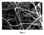
図3に、その結果形成されたCNT凝集体のSEM像が示されている。該凝集体は、1mmよりも大きい直径を有しており、「ナノ標準(またはナノ基準、nano-standards)」によれば非常に大きい。図4では、直径に対する大きな長さの比を有する、多数の、高度に交絡したCNTを見ることができる、CNT凝集体の拡大像が示される。図4から判るように、該CNTは、個々のCNTが、多数の、その間の(inbetween)屈曲および曲がりとともに、比較的短い直線部分のみを有するため、「巻いている(またはカールした、curly)」または「縮れた(kinky)」形状を有する。この巻きやすさ(または巻く傾向、curliness)または縮れやすさ(または縮れる傾向、kinkiness)は、本明細書内で、「多重スクロール構造(multi-scroll structure)」と呼ばれるCNTの特有の構造に関係すると考えられている。多重スクロール構造は、それぞれのグラファイト層が、2以上の重なり合ったグラフェン層から成る、1以上の巻き取られたグラファイト層から成る構造である。この構造は、本出願の優先日の後に公開されたドイツ特許公開公報第10 2007 044 031号で最初に報告されている。
FIG. 3 shows an SEM image of the resulting CNT aggregate. The agglomerates have a diameter greater than 1 mm and are very large according to “nano-standards”. In FIG. 4, a magnified image of CNT aggregates is shown where a large number of highly entangled CNTs with a large length to diameter ratio can be seen. As can be seen from FIG. 4, the CNTs are “rolled” (or curly) because individual CNTs have only a relatively short straight section, with numerous inbetween bends and bends. "Or" kinky "shape. This ease of winding (or tendency to curl, curliness) or ease of shrinking (or tendency to shrink, kinkiness) is related to the specific structure of the CNT, referred to herein as the “multi-scroll structure”. It is considered to be. The multiple scroll structure is a structure in which each graphite layer is composed of one or more wound graphite layers, each composed of two or more overlapping graphene layers. This structure was first reported in
以下の表1に、図1の装置で製造された高純度の多重スクロールCNTの特徴的な特性が要約されている。
CNTは、95重量%よりも大きい、非常に高い炭素の純度を有することに留意されたい。また、平均の外径は、長さが1μmから10μmにおいて、13nmのみである、すなわち、CNTは非常に高いアスペクト比を有する。更なる優れた特性は、130kg/m3から150kg/m3の範囲である高い嵩密度である。この高い嵩密度は、CNT凝集体の粉末の取り扱いを大幅に容易にし、容易な注入(pouring)およびその効率的な貯蔵(storing)を可能にする。このことは、産業スケールで本発明の複合材料に適用される場合、非常に重要である。 Note that CNTs have a very high carbon purity, greater than 95% by weight. Further, the average outer diameter is only 13 nm when the length is 1 μm to 10 μm, that is, CNT has a very high aspect ratio. A further excellent property is the high bulk density which is in the range of 130 kg / m 3 to 150 kg / m 3 . This high bulk density greatly facilitates the handling of the CNT aggregate powder and allows for easy pouring and its efficient storage. This is very important when applied to the composite material of the present invention on an industrial scale.
表1の特性を有するCNT凝集体は、大量処理して、急速に、かつ効率的に、製造できる。今日でさえ、本出願人は、すでに、この種のCNT凝集体を年60トン製造する能力を有している。 CNT aggregates having the properties shown in Table 1 can be processed in large quantities and rapidly and efficiently. Even today, Applicants already have the capacity to produce 60 tons of this type of CNT aggregates per year.
表2に、より低い生産能力ではあるが、本出願人が、また、製造できる非常に高い純度のCNT凝集体に関する上記と同じ特性が、要約されている。
図5は、CNT凝集体の粒子サイズの分布のグラフを示す。横軸は、μmで粒子サイズを表し、縦軸は、累積の容量(または累積の容積測定の含有量、cumulative volumetric content)を表す。図5のグラフから判るように、CNT凝集体のほとんど全ては、100μmよりも大きいサイズを有する。このことは、実際には、全てのCNT凝集体が、標準フィルターによって捕集(filter)できることを意味する。これらのCNT凝集体は、欧州特許第15051号によれば、呼吸性粉塵化の程度が低い。従って、本願発明の好ましい実施形態に用いられる極めて大きなCNT凝集体は、研究室から産業スケールに、本製造技術を移転する場合、最も重要でもある、CNTの安全かつ容易な取り扱いを可能にする。また、大きなCNT凝集体のサイズに起因して、CNT粉末は、その取り扱いを大幅に容易にもする、優れた注入性(pourabilty)を有する。従って、CNT凝集体は、ナノスケールの材料の特徴とマクロスケールの取り扱い性とを組み合わせることを可能にする。 FIG. 5 shows a graph of the particle size distribution of CNT aggregates. The horizontal axis represents particle size in μm, and the vertical axis represents cumulative volumetric (or cumulative volumetric content). As can be seen from the graph of FIG. 5, almost all of the CNT aggregates have a size greater than 100 μm. This means that in practice all CNT aggregates can be filtered by a standard filter. These CNT aggregates have a low degree of respiratory dusting according to EP 15051. Thus, the extremely large CNT aggregates used in the preferred embodiments of the present invention allow for safe and easy handling of CNTs, which is most important when transferring this manufacturing technology from the laboratory to the industrial scale. Also, due to the size of the large CNT aggregates, the CNT powder has excellent pourabilty that greatly facilitates its handling. Thus, CNT aggregates allow a combination of nanoscale material characteristics and macroscale handleability.
2.CNTの機能化
好ましい実施形態では、CNTは、メカニカルアロイングを実施する前に機能化される。機能化の目的は、複合材料の金属結晶のナノ安定化が向上できるよう、CNTを処理することである。好ましい実施形態では、この機能化は、CNTの少なくともいくらかの表面を凹凸化することによって実現される。
2. Functionalization of CNTs In a preferred embodiment, the CNTs are functionalized prior to performing mechanical alloying. The purpose of functionalization is to treat the CNTs so that the nanostabilization of the metal crystals of the composite material can be improved. In a preferred embodiment, this functionalization is achieved by roughening at least some surface of the CNT.
ここで、図6aに示されるCNT凝集体に、100kg/cm2(9.8MPa)の高圧が付与される。この圧力を付与する際に、図6bに示すように、その凝集体構造自体は、維持される、すなわち、機能化されたCNTは、呼吸性粉塵化の低下と、容易な取り扱いとに関する上述の利点を保持する凝集体の形態で、まだ存在する。また、CNTが同じ内部の構造を維持する一方で、1または複数の最外層が破裂するか、または破壊し、それによって、図6cに示すように、凹凸面を生ずることが見出されている。凹凸面により、CNTと結晶との組み合わせ効果が向上し、そして、ナノ安定化効果を向上させる。 Here, a high pressure of 100 kg / cm 2 (9.8 MPa) is applied to the CNT aggregate shown in FIG. 6a. In applying this pressure, as shown in FIG. 6b, the aggregate structure itself is maintained, i.e., the functionalized CNTs have been described above with respect to reduced respiratory dusting and easy handling. It still exists in the form of aggregates that retain the benefits. It has also been found that CNTs maintain the same internal structure, while one or more outermost layers rupture or break, thereby producing an uneven surface, as shown in FIG. 6c. . The uneven surface improves the combined effect of CNT and crystals and improves the nano-stabilizing effect.
3.噴霧による金属粉末の生成
図7に、噴霧により金属粉末を生成するための装置24が示されている。装置24は、本発明の複合材料の構成要素として用いられる金属または金属の合金が、その中に溶融している、加熱手段を有する容器(または管、vessel)を含む。矢印32によって示されて、液体金属または液体合金は、チャンバー30内に注がれ、アルゴン噴射(driving)ガスによって、ノズルアセンブリ34を通って不活性ガスを含むチャンバー36に送り込まれる。チャンバー36では、ノズルアセンブリ34から出ていく液体金属の噴霧は、アルゴン急冷ガス38によって急冷され、その結果、金属の液滴が、急速に凝固し、チャンバー36の床に堆積する金属粉末40を形成する。この粉末は、本願発明の複合材料の金属成分を形成する。
3. Generation of Metal Powder by Spraying FIG. 7 shows an
4.金属粉末の高エネルギーミル粉砕および金属中でのCNTの機械的分散
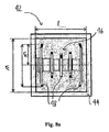
1節(またはセクション1)で示されるように製造され、かつ2節で示されるように機能化されたCNTと、3節で示されるように製造された金属の粉末とから複合材料を形成するように、CNTは、金属内部に分散される必要がある。好ましい実施形態では、このことは、図8aの側断面図および図8bの端断面図に示される、高エネルギーミル42で実施されるメカニカルアロイングによって実現される。高エネルギーミル42は、多数の回転アーム48を有する回転要素46が、回転要素46の回転軸が水平方向に延在するように配置されたミルチャンバー44を含む。図8の概略図では示されないが、回転要素46は、回転数が毎分1500回転以下、もしくはそれ以上にまで駆動するように、駆動手段に接続される。とりわけ、半径方向に、外側に位置するそれぞれのアーム48の先端が、少なくとも8.0m/秒、好ましくは11.0m/秒よりも大きい速度を、それ自体が固定されたままであるミルチャンバー44に対して得るよう、回転要素46が回転速度で駆動することができる。図8に示されないが、多数のボールは、ミル部材として、ミルチャンバー44内に備えられる。より詳細に以下に記載される2つのボール50の拡大図が、図9に示される。本実施例では、ボールは、鋼により作製され、直径5.1mmを有する。別の実施形態では、ボール50は、ZiO2またはイットリア安定化前記ZiO2より作製することができる。
4). High energy milling of metal powder and mechanical dispersion of CNTs in metal CNTs produced as shown in Section 1 (or Section 1) and functionalized as shown in
メカニカルアロイングの原理は、図9を参照して説明される。メカニカルアロイングは、粉末粒子52が、粉砕ボール(grinding ball)50の高いエネルギーの衝突により繰り返される、変形、破砕および溶接により処理されるプロセスである。メカニカルアロイングの過程で、CNT凝集体は分解され、金属粉末の粒子は砕け、このプロセスを経て、単一のCNTが、金属マトリックス内部に分散する。ボールの運動エネルギーは、速度に2乗して(または2次的に、quadratically)依存するため、ボールを10m/秒以上の非常に高い速度にまで加速させることが、主要な目的である。本願発明者らは、高速のストロボのシネマトポグラフィー(high speed stroboscopic cinematopography)を用いて、ボールの運動を分析しており、ボールの最大相対速度が回転アーム48の先端の最大速度におおよそ一致することを確認できている。
The principle of mechanical alloying is explained with reference to FIG. Mechanical alloying is a process in which the powder particles 52 are processed by deformation, crushing and welding, which are repeated by high energy impact of a grinding ball 50. In the process of mechanical alloying, the CNT aggregates are decomposed and the metal powder particles are crushed. Through this process, single CNTs are dispersed inside the metal matrix. Since the ball's kinetic energy depends on the velocity squared (or quadratically), it is a major goal to accelerate the ball to a very high velocity of 10 m / sec or more. The present inventors have analyzed the motion of the ball using high speed stroboscopic cinematopography, and the maximum relative velocity of the ball approximately matches the maximum velocity of the tip of the
全ての種類のボールミルでは、処理される媒体に、衝突力、せん断力および摩擦力が付与されるがしかし、より高い運動エネルギーでは、衝突により移されるエネルギーの相対量は増加する。本願発明の構成において、処理される媒体に与えられる全ての機械加工からの、衝突の相対的な寄与は、可能な限り高いことが好ましい。この理由のために、図8に示される高エネルギーボールミル42は、到達できるボールの運動エネルギーが、より高いので、通常のドラム型ボールミル(drum-ball mill)、遊星ボールミルまたはアトライター(attritor)よりも好都合である。例えば、遊星ボールミルまたはアトライターにおいて、ボールの最大相対速度は、通常、5m/秒以下である。ボールがミルチャンバーの回転によって動くように設定されるドラム型ボールミルでは、ボールの最大速度は、ミルチャンバーの回転速度およびミルチャンバーのサイズの両方に依存するであろう。低回転速度では、ボールは、摩擦力とせん断力とが支配する、いわゆる「カスケードモード(cascade mode)」で動く。高回転数では、ボールの動きは、自由落下モード(mode)において、重力に起因してボールが加速する、いわゆる「カタラクトモード(cataract mode)」になり、従って、最大速度は、ボールミルの直径に依存するであろう。しかしながら、利用可能な最も大きなドラム型ボールミルでさえ、最大速度は、7m/秒を超えることは困難であろう。従って、図8に示されるような、固定されたミルチャンバー44と、駆動する回転要素46とを有するHEMの構成は好ましい。
In all types of ball mills, impact, shear and friction forces are imparted to the media being processed, but at higher kinetic energy, the relative amount of energy transferred by the impact increases. In the configuration of the present invention, the relative contribution of collision from all machining imparted to the media to be processed is preferably as high as possible. For this reason, the high
高いエネルギーの衝突に起因する金属の第2の効果は、結晶の転位密度の増加に起因した加工硬化の効果である。転位が堆積して、互いに相互作用し、転位の動きを著しく遅らせるピンニング点または障害物として働く。このことは、また、材料の降伏強度σyの増加およびそれに続く延性の減少をもたらす。 The second effect of the metal due to high energy collision is the effect of work hardening due to an increase in the crystal dislocation density. Dislocations accumulate and interact with each other and act as pinning points or obstacles that significantly slow the movement of the dislocations. This also results in an increase in the yield strength σ y of the material and a subsequent decrease in ductility.
しかしながら、多くの金属、とりわけアルミニウムのような軽金属は、高エネルギーミル粉砕による処理を困難にする、極めて高い延性を有する。その高い延性のために、該金属は、ミルチャンバー44の内壁または回転要素46に付着しやすく、従って完全には粉砕されない場合がある。このような付着は、ステアリン酸等のミル粉砕助剤(aid)を用いることによって防止できる。本願と同じ発明者らによる国際公開公報第2009/010297号では、CNT自体は、金属の粉末の付着を防止するミル粉砕剤(agent)として働くことができることが説明されていた。しかしながら、金属粉末およびCNTが、同時に、十分なエネルギーで、かつ十分な時間、金属の結晶のサイズを100nm以下にまで減少させるよう、粉砕する場合に、CNTは、予想されるナノ安定化が大幅に損なわれる程度にまで損傷される傾向があろう。
However, many metals, especially light metals such as aluminum, have extremely high ductility that makes processing by high energy milling difficult. Due to its high ductility, the metal tends to adhere to the inner wall of the
好ましい実施形態によれば、高エネルギーミル粉砕は、従って、2つの段階で実施される。第1の段階では、金属の粉末と、CNTの粉末のわずかな部分とが処理される。この第1の段階は、200nmより小さい平均サイズ、好ましくは100nmより小さい平均サイズを有する金属結晶を生成するのに適した時間、通常、20分間から60分間、実施される。この第1の段階では、金属の付着を防止することができるであろう最少量のCNTが添加される。このCNTはミル粉砕剤として犠牲になる、つまり、完成した複合材料において、重要なナノ安定化効果を有さないであろう。 According to a preferred embodiment, the high energy milling is therefore carried out in two stages. In the first stage, the metal powder and a small portion of the CNT powder are processed. This first stage is carried out for a time suitable for producing metal crystals having an average size of less than 200 nm, preferably less than 100 nm, usually 20 to 60 minutes. In this first stage, the minimum amount of CNT that would be able to prevent metal deposition is added. This CNT will be sacrificed as a mill grinder, ie it will not have a significant nanostabilizing effect in the finished composite.
第2の段階では、残りのCNTが加えられ、CNTおよび金属のメカニカルアロイングが実施される。この段階では、図3および図6bに示されるようなミクロスケールの凝集体が、メカニカルアロイングによって、金属マトリックス中に分散する、単一のCNTに分解される必要がある。実験では、高エネルギーミル粉砕によって、CNT合金を分解することが、実際に、容易に可能であることが確認されており、このことは、他の分散方法では、達成するのが困難であろう。また、第2の段階の間に加えられた、金属マトリックス内部のCNTの統合性が、非常に良く、従ってナノ安定化の効果を可能にすることが観察されている。金属マトリックス中の交絡していないCNTの統合性に関して、大きいサイズの凝集体を用いることは、凝集体の内側のCNTが、外側のCNTによってある程度保護されているため、より好都合であると考えられる。 In the second stage, the remaining CNT is added and mechanical alloying of CNT and metal is performed. At this stage, the microscale aggregates as shown in FIGS. 3 and 6b need to be broken down by mechanical alloying into single CNTs dispersed in the metal matrix. Experiments have confirmed that CNT alloys can actually be easily decomposed by high energy milling, which may be difficult to achieve with other dispersion methods. . It has also been observed that the integrity of the CNTs inside the metal matrix, added during the second stage, is very good, thus enabling the effect of nanostabilization. With regard to the integrity of unentangled CNTs in the metal matrix, it may be more convenient to use large size aggregates because the inner CNTs of the aggregates are protected to some extent by the outer CNTs. .
更に、第1の段階では、回転要素46の回転速度は、図10のタイミングチャートに示されるように、好ましくは、周期的に上昇および降下する。図10から判るように、回転速度は、交互の周期(すなわち、4分間、毎分1500回転の高速サイクルおよび1分間、毎分800回転の低速サイクル)で制御される。回転速度の当該周期的な変調は、付着を妨げることが見出されている。このような周期運転は、ドイツ特許公報第196 35 500号にすでに開示され、本願発明の構成に、首尾よく適用されている。
Furthermore, in the first stage, the rotational speed of the
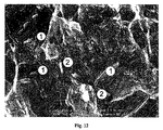
上述の処理によって、高転位密度と、200nmより小さい平均サイズ、好ましくは100nmの平均サイズとを有する金属結晶が、均一に分布したCNTによって、少なくとも部分的に分離され、かつ、マクロに安定化されている粉末の複合材料を得ることができる。図11aは、本願発明の実施形態に係る複合材料粒子の切断面を示す。図11aでは、金属成分は、アルミニウムであり、CNTは、上述の1節に示される処理によって得られた多重スクロール型である。図11aから判るように、複合材料は、CNTの網目構造に位置する、ナノスケールの金属結晶の等方的な分布により特徴付けられる。これと対照的に、図11bに示される国際公開公報第2008/052642号の複合材料は、不等方的な機械的特性をもたらす不等方的な層構造を有している。
By the above-described treatment, metal crystals having a high dislocation density and an average size of less than 200 nm, preferably an average size of 100 nm, are at least partially separated and uniformly stabilized by uniformly distributed CNTs. A powdered composite material can be obtained. FIG. 11a shows a cut surface of a composite material particle according to an embodiment of the present invention. In FIG. 11a, the metal component is aluminum and the CNT is a multi-scroll type obtained by the process shown in
好ましい実施形態では、複合粉末は、不動態化容器(または不動態化管、passivation vessel)内で(図示せず)不動態化処理が行われる。この不動態化において、完成した複合粉末は、ミルチャンバー42から排出され、さらに、真空中または不活性ガス雰囲気下で、不動態化容器に排出される。不動態化容器内で、複合材料は、ゆっくりと攪拌され、複合粉末をゆっくりと酸化させるよう、酸素が徐々に加えられる。この不動態化がゆっくりと実施されるほど、複合粉末の全酸素取り込み総量は、低下する。
In a preferred embodiment, the composite powder is passivated (not shown) in a passivating vessel (or passivating vessel). In this passivation, the finished composite powder is discharged from the
粉末の不動態化は、また、産業スケールにおける、製品または半完成品の製造用の原材料としての粉末の取り扱いを容易にする。 Powder passivation also facilitates the handling of powders as raw materials for the manufacture of products or semi-finished products on an industrial scale.
5.複合金属粉末の圧縮
複合材料の粉末は、粉末冶金法によって、半完成品または完成品を形成するための原材料として用いられ得る。とりわけ、本願発明の粉末材料は冷間等方圧加工(CIP)および熱間等方圧加工(HIP)によって、非常に好都合的に、更に処理できる。また、複合材料は、いくつかの金属相の融点に近い高温における、熱間加工、粉末ミル粉砕または粉末押出しによって更に処理できる。CNTのナノ安定化効果に起因して、複合材料が粉末押出しまたは流動成形(または流れ押出し、flow pressing)によって処理できるほど、複合材料の粘性が高温でさえ増加することが観察されている。また、該粉末は連続した粉末圧延によって直接処理することもできる。
5. Compression of composite metal powders Composite powders can be used as raw materials to form semi-finished products or finished products by powder metallurgy. In particular, the powder material of the present invention can be further processed very conveniently by cold isostatic pressing (CIP) and hot isostatic pressing (HIP). The composite material can also be further processed by hot working, powder milling or powder extrusion at high temperatures close to the melting points of some metal phases. Due to the nano-stabilizing effect of CNTs, it has been observed that the viscosity of the composite increases even at high temperatures, so that the composite can be processed by powder extrusion or flow molding (or flow pressing). The powder can also be processed directly by continuous powder rolling.
圧縮した、完成品または半完成品において、粉末粒子の優れた機械的特性が維持できることは、本願発明の複合材料の優れた利点である。例えば、多重スクロールCNTとAl5xxxとを用いる場合に、上述の4節に示されるようなメカニカルアロイング法を用いることによって、390HVよりも大きいビッカース硬さを有する複合材料が得られた。とりわけ、粉末材料を完成品または半製品に対して圧縮した後でさえ、ビッカース硬さはこの値の80%よりも大きい値に維持される。すなわち、ナノ構造を安定化させることに起因して、それぞれの複合粉末粒子の硬度は、圧縮した物品に大部分引き継ぐ(transfer)ことができる。本願発明以前に、圧縮した物品のこのような硬度は、不可能であった。 The ability to maintain the excellent mechanical properties of the powder particles in a compressed, finished or semi-finished product is an excellent advantage of the composite material of the present invention. For example, when multiple scroll CNT and Al5xxx are used, a composite material having a Vickers hardness greater than 390 HV was obtained by using the mechanical alloying method as described in Section 4 above. In particular, the Vickers hardness is maintained at a value greater than 80% of this value even after the powder material has been compressed against the finished product or semi-finished product. That is, due to the stabilization of the nanostructure, the hardness of each composite powder particle can be largely transferred to the compressed article. Prior to the present invention, such hardness of compressed articles was not possible.
好ましい例示的な実施形態は、添付図面および本明細書において、詳細に示され、および規定されているがしかし、これらは、純粋に例と見なされるべきであり、本願発明を制限するものとして見なされるべきではない。好ましい例示的な実施形態のみが示され、および規定されていること、ならびに全ての変形例と改良が、添付の請求項の保護の範囲内にあり、現在または将来において、保護されるべきであることに留意されたい。
Preferred exemplary embodiments are shown and defined in detail in the accompanying drawings and specification, however, these are to be regarded as purely examples and are regarded as limiting the present invention. Should not be. Only the preferred exemplary embodiments have been shown and defined, and all variations and modifications are within the scope of protection of the appended claims and should be protected now or in the future. Please note that.
10 触媒化学蒸着装置
12 流動床反応器
14 加熱手段
16 下部入口
18 上部排出開口
20 触媒入口
22 排出開口
24 噴霧による金属粉末の生成装置
26 容器
28 加熱手段
30 チャンバー
32 アルゴン噴射ガス
34 ノズルアセンブリ
36 チャンバー
38 アルゴン急冷ガス
40 金属粉末
42 高エネルギーミル
44 ミルチャンバー
46 回転要素
48 回転要素46のアーム
50 ミル粉砕ボール
DESCRIPTION OF
Claims (44)
1nmから100nmの範囲の平均サイズ、好ましくは、10nmから100nmの範囲の平均サイズ、または100nmより大きくかつ200nm以下の範囲の平均サイズを有し、前記ナノ粒子によって少なくとも部分的に互いに分離される金属結晶を含む複合材料を形成するよう、メカニカルアロイングによって金属粉末および前記ナノ粒子を処理する工程を含むことを特徴とする金属およびナノ粒子、とりわけカーボンナノチューブ(CNT)を含む複合材料を製造する方法。 A method for producing a composite material comprising metals and nanoparticles, in particular carbon nanotubes (CNT), comprising:
Metals having an average size in the range of 1 nm to 100 nm, preferably an average size in the range of 10 nm to 100 nm, or an average size in the range of greater than 100 nm and less than or equal to 200 nm, at least partially separated from each other by the nanoparticles Process for producing a composite material comprising metal and nanoparticles, in particular carbon nanotubes (CNT), comprising the step of treating the metal powder and said nanoparticles by mechanical alloying to form a composite material comprising crystals .
前記第1の処理段階では、前記金属のほとんどまたは全てが処理され、
前記第2の処理段階では、ナノ粒子、とりわけCNTが加えられ、前記金属および前記ナノ粒子が同時に処理されることを特徴とする請求項1〜21のいずれか1項に記載の方法。 Said treatment of the metal powder and nanoparticles comprises first and second treatment steps;
In the first treatment stage, most or all of the metal is treated;
22. A method according to any one of the preceding claims, wherein in the second treatment stage, nanoparticles, in particular CNT, are added and the metal and the nanoparticles are treated simultaneously.
Applications Claiming Priority (5)
| Application Number | Priority Date | Filing Date | Title |
|---|---|---|---|
| DE102009009110.6 | 2009-02-16 | ||
| DE102009009110 | 2009-02-16 | ||
| EPPCT/EP2009/006737 | 2009-09-17 | ||
| PCT/EP2009/006737 WO2010091704A1 (en) | 2009-02-16 | 2009-09-17 | A compound material comprising a metal and nano particles and a method for producing the same |
| PCT/EP2010/000520 WO2010091790A1 (en) | 2009-02-16 | 2010-01-28 | A compound material comprising a metal and nanoparticles and a method for producing the same |
Publications (2)
| Publication Number | Publication Date |
|---|---|
| JP2012518079A true JP2012518079A (en) | 2012-08-09 |
| JP2012518079A5 JP2012518079A5 (en) | 2013-03-14 |
Family
ID=41572320
Family Applications (3)
| Application Number | Title | Priority Date | Filing Date |
|---|---|---|---|
| JP2011549460A Pending JP2012518079A (en) | 2009-02-16 | 2010-01-28 | COMPOSITE MATERIAL CONTAINING METAL AND NANOPARTICLE AND METHOD FOR PRODUCING THE SAME |
| JP2011549459A Pending JP2012518078A (en) | 2009-02-16 | 2010-01-28 | Engine or engine component and method for manufacturing the same |
| JP2011549461A Pending JP2012518080A (en) | 2009-02-16 | 2010-01-28 | Coupling means, manufacturing method thereof, and material joining |
Family Applications After (2)
| Application Number | Title | Priority Date | Filing Date |
|---|---|---|---|
| JP2011549459A Pending JP2012518078A (en) | 2009-02-16 | 2010-01-28 | Engine or engine component and method for manufacturing the same |
| JP2011549461A Pending JP2012518080A (en) | 2009-02-16 | 2010-01-28 | Coupling means, manufacturing method thereof, and material joining |
Country Status (11)
| Country | Link |
|---|---|
| US (4) | US20120270059A1 (en) |
| JP (3) | JP2012518079A (en) |
| KR (3) | KR20110128816A (en) |
| CN (3) | CN102395697A (en) |
| AU (1) | AU2010213174A1 (en) |
| BR (3) | BRPI1008268A2 (en) |
| CA (1) | CA2752448A1 (en) |
| ES (2) | ES2404054T3 (en) |
| RU (1) | RU2011137946A (en) |
| TW (3) | TW201107489A (en) |
| WO (5) | WO2010102655A2 (en) |
Cited By (6)
| Publication number | Priority date | Publication date | Assignee | Title |
|---|---|---|---|---|
| JP2014111939A (en) * | 2012-12-04 | 2014-06-19 | Pfeiffer Vacuum Gmbh | Vacuum pump |
| CN109093108A (en) * | 2018-08-30 | 2018-12-28 | 桂林电子科技大学 | High starch breeding alkene-carbon nanotube mixing Cu-base composites and preparation method thereof |
| CN109609806A (en) * | 2018-07-05 | 2019-04-12 | 重庆大学 | A kind of graphene oxide enhancing titanium composite material and preparation method thereof |
| CN111593226A (en) * | 2020-06-16 | 2020-08-28 | 江西省科学院应用物理研究所 | Graphene/copper composite material and preparation method thereof |
| CN111876622A (en) * | 2020-06-22 | 2020-11-03 | 南京理工大学 | Preparation method of graphene reinforced aluminum alloy tensile heat-conducting composite material |
| CN112593107A (en) * | 2020-11-25 | 2021-04-02 | 深圳市富士锦电子科技有限公司 | Equipment and method for preparing graphene aluminum alloy |
Families Citing this family (62)
| Publication number | Priority date | Publication date | Assignee | Title |
|---|---|---|---|---|
| JP5334769B2 (en) * | 2009-09-10 | 2013-11-06 | 独立行政法人物質・材料研究機構 | High strength bolt |
| GB2485339B (en) | 2010-11-02 | 2018-10-03 | Cambridge Entpr Ltd | Method of making carbon nanotubes |
| CN102127721A (en) * | 2010-11-03 | 2011-07-20 | 映瑞光电科技(上海)有限公司 | Aluminum alloy material and preparation method of aluminum alloy back plate |
| CN102724615B (en) * | 2011-03-29 | 2015-03-11 | 清华大学 | A thermal sounding device and an electronic device |
| CN102724621B (en) * | 2011-03-29 | 2015-07-01 | 清华大学 | Thermoacoustic device and electronic device |
| CN102724614B (en) * | 2011-03-29 | 2015-06-03 | 清华大学 | A thermal sounding device and an electronic device |
| CN102145883B (en) * | 2011-04-29 | 2013-07-03 | 清华大学 | Directly-prepared ultrahigh-purity carbon nanotube and preparation method thereof |
| CN102851557A (en) * | 2011-06-30 | 2013-01-02 | 鸿富锦精密工业(深圳)有限公司 | Graphene-doped magnesium alloy and magnesium alloy member |
| US10079389B2 (en) | 2012-05-18 | 2018-09-18 | Xg Sciences, Inc. | Silicon-graphene nanocomposites for electrochemical applications |
| RU2508961C2 (en) * | 2012-05-22 | 2014-03-10 | Федеральное государственное бюджетное образовательное учреждение высшего профессионального образования "Ульяновский государственный технический университет" | Method of making 3d complex-shape nanostructured structural and functional materials |
| US10815124B2 (en) | 2012-07-12 | 2020-10-27 | Seerstone Llc | Solid carbon products comprising carbon nanotubes and methods of forming same |
| CN104619637B (en) * | 2012-07-12 | 2017-10-03 | 赛尔斯通股份有限公司 | Solid carbon product comprising CNT with and forming method thereof |
| CN103343331B (en) * | 2013-07-02 | 2015-07-01 | 中国航空工业集团公司北京航空制造工程研究所 | Chemical vapor deposition reaction device |
| TW201504463A (en) * | 2013-07-16 | 2015-02-01 | Univ Ming Chi Technology | Alloy grain refining method |
| EP3041968B1 (en) * | 2013-09-05 | 2018-10-24 | Dresser-Rand Company | Turbomachine components manufactured with carbon nanotube composites |
| CN103602933B (en) * | 2013-12-09 | 2016-03-02 | 国家电网公司 | Height leads carbon-nanotube-modialuminum aluminum material and preparation method thereof |
| KR20150071591A (en) * | 2013-12-18 | 2015-06-26 | 현대자동차주식회사 | Nano-carbon composite and method for producing the same |
| CN104451475B (en) * | 2014-12-15 | 2016-11-30 | 青岛玉兰祥商务服务有限公司 | A kind of Al alloy composite and preparation method thereof |
| CN104561676A (en) * | 2015-01-13 | 2015-04-29 | 淄博博旭再生能源科技有限公司 | Inner pipe for solar water heater |
| CN104841928B (en) * | 2015-06-02 | 2017-02-22 | 山东珠峰车业有限公司 | Rear axle shaft of fuel-electric hybrid power tricycle and preparation technology of rear axle shaft |
| CN105108133A (en) * | 2015-06-25 | 2015-12-02 | 中国航空工业集团公司北京航空材料研究院 | Grapheme and metal mixing powder and preparation method thereof |
| CN106191494B (en) * | 2016-06-30 | 2018-07-20 | 上海交通大学 | Carbon nanotube enhances the metallurgical preparation method of titanium matrix composite |
| CN105965025B (en) * | 2016-07-13 | 2017-09-19 | 江苏省特种设备安全监督检验研究院 | It is a kind of to produce high-strength, the high method and device for leading graphene copper-based powder material |
| CN106591622B (en) * | 2016-12-30 | 2018-07-24 | 宁波墨西科技有限公司 | A kind of composite modified copper-iron alloy of graphene-carbon nano tube and preparation method thereof |
| US10960497B2 (en) * | 2017-02-01 | 2021-03-30 | Hrl Laboratories, Llc | Nanoparticle composite welding filler materials, and methods for producing the same |
| JP6821479B2 (en) * | 2017-03-16 | 2021-01-27 | 昭和電工株式会社 | Materials for plastic working, plastic working bodies and thermal conductors |
| RU2659961C1 (en) * | 2017-05-29 | 2018-07-04 | Общество с ограниченной ответственностью "Новая Химия" | Composite elastic material and method of its manufacturing |
| CN107377104B (en) * | 2017-08-10 | 2023-05-26 | 贵州理工学院 | Preparation method and device of high-performance nano powder material |
| CN110157931B (en) * | 2018-02-13 | 2021-05-04 | 哈尔滨工业大学 | Nano carbon reinforced metal matrix composite material with three-dimensional network structure and preparation method thereof |
| CN108723712A (en) * | 2018-05-29 | 2018-11-02 | 南京钢铁股份有限公司 | A kind of high anti-corrosion container super austenitic stainless steel composite plate and preparation method |
| WO2020102539A1 (en) * | 2018-11-15 | 2020-05-22 | The Regents Of The University Of California | Scalable manufacturing of copper nanocomposites with unusual properties |
| CN111349810B (en) * | 2018-12-24 | 2022-01-07 | 有研工程技术研究院有限公司 | Graphene/copper composite wire and preparation method thereof |
| CN109530708A (en) * | 2019-01-14 | 2019-03-29 | 西南交通大学 | A kind of nano-sized carbon enhancing titanium-based/nano HA composite material and preparation method |
| CN109746415B (en) * | 2019-03-15 | 2020-07-07 | 中国兵器工业第五九研究所 | Extrusion casting forming method for Al-Si series aluminum alloy member |
| CN110157853B (en) * | 2019-04-28 | 2021-05-07 | 河南科技大学 | Short-process preparation device and method for high-density composite material |
| CN110129606B (en) * | 2019-05-23 | 2021-02-09 | 昆明理工大学 | Preparation method of directionally arranged carbon nanotube reinforced aluminum-based composite wire |
| GB201908011D0 (en) | 2019-06-05 | 2019-07-17 | Silberline Ltd | New product |
| CN110055444A (en) * | 2019-06-13 | 2019-07-26 | 中国矿业大学 | A kind of preparation method of highly conductive graphene/aluminum based composites |
| CN110157933B (en) * | 2019-06-25 | 2020-11-06 | 西安建筑科技大学 | Preparation method of high-strength wear-resistant non-oriented graphene/Ti 2AlNb composite material |
| CN110724842B (en) * | 2019-10-30 | 2021-07-30 | 中国科学院金属研究所 | High-strength and high-toughness carbon nano tube reinforced aluminum composite material with non-uniform structure and preparation method thereof |
| CN114630720A (en) * | 2019-11-08 | 2022-06-14 | 大同特殊钢株式会社 | Powder material |
| CN112481518A (en) * | 2019-12-26 | 2021-03-12 | 浙江杭机新型合金材料有限公司 | High-strength high-conductivity copper-titanium alloy material and preparation method thereof |
| KR20210093653A (en) * | 2020-01-20 | 2021-07-28 | 부경대학교 산학협력단 | Method for manufacturing aluminum composite cylinder head for compression machinery and aluminum composite cylinder head manufactured thereby |
| CN111748708A (en) * | 2020-07-08 | 2020-10-09 | 沧州渤海防爆特种工具集团有限公司 | Titanium-copper alloy explosion-proof material and preparation method thereof |
| RU2748974C1 (en) * | 2020-07-28 | 2021-06-02 | Федеральное государственное бюджетное учреждение науки Институт проблем химической физики Российской Академии наук (ФГБУН ИПХФ РАН) | Nickel-containing carbon-graphene hydrogenation catalyst and method for its preparation |
| CN112108645B (en) * | 2020-09-04 | 2022-07-08 | 吉林师范大学 | Superparamagnetic small-size alloy nanoparticle and preparation method thereof |
| CN112342420B (en) * | 2020-10-16 | 2022-03-22 | 湘潭大学 | Preparation method of high-strength high-toughness corrosion-resistant deformation CNTs reinforced Zn-Al-based composite material |
| CN112458384B (en) * | 2020-11-25 | 2022-08-02 | 浙江炜烨晶体纤维有限公司 | Adopt polycrystal mullite fibre heat retaining discharge plasma sintering mould |
| CN112853142B (en) * | 2020-12-31 | 2022-02-18 | 北京石墨烯技术研究院有限公司 | Graphene-modified metal composite material |
| CN112921731B (en) * | 2021-01-28 | 2022-04-01 | 武汉大学 | Reinforced gravel pile supported EPS light embankment structure in soft soil area and construction method |
| CN112945729B (en) * | 2021-02-02 | 2022-09-16 | 中南大学 | Method for predicting ball-milling related tensile strength of graphene/aluminum nanocomposite |
| CN112759409B (en) * | 2021-02-07 | 2022-01-14 | 内蒙古中晶科技研究院有限公司 | Carbon/carbon composite material vapor deposition process |
| CN113005317A (en) * | 2021-02-24 | 2021-06-22 | 山东省科学院新材料研究所 | High-thermal-stability magnesium alloy with mixed crystal structure and controllable preparation method and application |
| CN113198840B (en) * | 2021-04-22 | 2022-04-12 | 武汉大学 | Method for preparing graphene from carbon nano tube and application of graphene |
| CN113249625B (en) * | 2021-05-07 | 2022-04-05 | 哈尔滨工程大学 | High-specific-strength magnesium-lithium-based composite material and preparation method thereof |
| CN113355548B (en) * | 2021-05-28 | 2022-06-14 | 上海交通大学 | Atmosphere control powder metallurgy preparation method of graphene reinforced aluminum matrix composite |
| CN113308630A (en) * | 2021-05-28 | 2021-08-27 | 昆明理工大学 | In-situ CNTs @ Ti hybrid reinforced aluminum matrix composite and preparation method thereof |
| CN113319284B (en) * | 2021-05-31 | 2022-02-15 | 中南大学 | Preparation method of co-injection multilayer structure part |
| CN114875261B (en) * | 2022-06-02 | 2022-10-28 | 哈尔滨工业大学 | Corrosion-resistant aluminum-carbon composite material and preparation method thereof |
| CN115584409B (en) * | 2022-06-29 | 2023-06-16 | 苏州新锐合金工具股份有限公司 | Preparation method of graphene reinforced and toughened titanium-based metal ceramic |
| WO2024024533A1 (en) * | 2022-07-29 | 2024-02-01 | 株式会社スパインテック | Bone screw |
| CN116103532B (en) * | 2023-02-28 | 2024-01-23 | 南昌大学 | Trace rare earth oxide reinforced oxygen-free copper material and preparation method thereof |
Citations (6)
| Publication number | Priority date | Publication date | Assignee | Title |
|---|---|---|---|---|
| JPH09209001A (en) * | 1996-02-08 | 1997-08-12 | Agency Of Ind Science & Technol | Highly efficient alloy powder synthesizing method by mechanical alloying method |
| JPH10168502A (en) * | 1996-12-10 | 1998-06-23 | Osaka Gas Co Ltd | Composite material with high thermal conductivity |
| JP2004140259A (en) * | 2002-10-18 | 2004-05-13 | Osaka Gas Co Ltd | Magnetic fluid |
| JP2007154246A (en) * | 2005-12-02 | 2007-06-21 | Nissei Plastics Ind Co | Method for producing carbon nanocomposite metal forming |
| WO2008052642A1 (en) * | 2006-10-31 | 2008-05-08 | Alcan Technology & Management Ltd. | Materials containing carbon nanotubes, process for producing them and use of the materials |
| JP2010159445A (en) * | 2009-01-07 | 2010-07-22 | Shinshu Univ | Method of mixing metal particle and carbon powder, method of producing metal-carbon composite material, and metal-carbon composite material |
Family Cites Families (22)
| Publication number | Priority date | Publication date | Assignee | Title |
|---|---|---|---|---|
| GB1469930A (en) | 1974-10-11 | 1977-04-06 | Atomic Energy Authority Uk | Carbon filaments |
| CA1175616A (en) | 1981-01-05 | 1984-10-09 | Exxon Research And Engineering Company | Production of iron monoxide and carbon filaments therefrom |
| DE4307083B4 (en) | 1993-03-06 | 2007-07-12 | Zoz Maschinenbau Gmbh | Device for fine grinding of solids |
| DE19504540B4 (en) | 1995-02-11 | 2005-02-10 | Zoz Maschinenbau Gmbh | Device for feeding or emptying a container, in particular a milling unit operating discontinuously with grinding bodies |
| DE19635500B4 (en) | 1996-09-03 | 2008-01-10 | Zoz Gmbh | Apparatus for the high-energy and / or pulverization of solids and method for its operation |
| US7323136B1 (en) * | 2000-02-01 | 2008-01-29 | William Marsh Rice University | Containerless mixing of metals and polymers with fullerenes and nanofibers to produce reinforced advanced materials |
| US6902699B2 (en) * | 2002-10-02 | 2005-06-07 | The Boeing Company | Method for preparing cryomilled aluminum alloys and components extruded and forged therefrom |
| JP2004285400A (en) * | 2003-03-20 | 2004-10-14 | Nissin Kogyo Co Ltd | Mounting member for vehicle |
| KR100582343B1 (en) * | 2003-03-26 | 2006-05-22 | 캐논 가부시끼가이샤 | Electrode material for lithium secondary battery, electrode structure comprising the electrode material and secondary battery comprising the electrode structure |
| US20050186104A1 (en) * | 2003-03-26 | 2005-08-25 | Kear Bernard H. | Composite materials containing a nanostructured carbon binder phase and high pressure process for making the same |
| WO2005040066A1 (en) * | 2003-10-29 | 2005-05-06 | Sumitomo Precision Products Co., Ltd. | Carbon nanotube-dispersed composite material, method for producing same and article same is applied to |
| JP2005139542A (en) * | 2003-11-10 | 2005-06-02 | Tamagawa Seiki Co Ltd | Method of forming motor component, and motor component |
| US20050133121A1 (en) * | 2003-12-22 | 2005-06-23 | General Electric Company | Metallic alloy nanocomposite for high-temperature structural components and methods of making |
| WO2005065281A2 (en) * | 2003-12-31 | 2005-07-21 | The Regents Of The University Of California | Articles comprising high-electrical-conductivity nanocomposite material and method for fabricating same |
| JP2006132416A (en) * | 2004-11-05 | 2006-05-25 | Nissan Motor Co Ltd | Internal combustion engine and method of manufacturing its combustion chamber component part |
| KR100841754B1 (en) | 2005-05-17 | 2008-06-27 | 연세대학교 산학협력단 | Fabrication methods of metal/polymer matrix composites containing randomly distributed or directionally aligned nanofibers and metal/polymercomplex produced by the method |
| US7699946B2 (en) * | 2005-09-07 | 2010-04-20 | Los Alamos National Security, Llc | Preparation of nanostructured materials having improved ductility |
| US8080335B2 (en) * | 2006-06-09 | 2011-12-20 | Canon Kabushiki Kaisha | Powder material, electrode structure using the powder material, and energy storage device having the electrode structure |
| KR20100093473A (en) * | 2006-12-27 | 2010-08-25 | 데이비드 브루스 게이건 | Transparent conductive nano-composites |
| CA2692959A1 (en) * | 2007-07-18 | 2009-01-22 | Alcan Technology & Management Ag | Duplex-aluminium material based on aluminium with a first phase and a second phase and method for producing the duplex-aluminium material |
| JP5077660B2 (en) | 2007-07-25 | 2012-11-21 | 三菱マテリアル株式会社 | COATING COMPOSITION FOR PRODUCING METAL POWDER COMPOSITE, METAL COMPOSITE MANUFACTURED BY THE METAL POWDER COMPOSITE, METAL LAMINATE COMPOSITE, AND METHOD FOR PRODUCING THEM |
| DE102007044031A1 (en) | 2007-09-14 | 2009-03-19 | Bayer Materialscience Ag | Carbon nanotube powder, carbon nanotubes and methods of making same |
-
2009
- 2009-09-17 WO PCT/EP2009/006745 patent/WO2010102655A2/en unknown
- 2009-09-17 WO PCT/EP2009/006737 patent/WO2010091704A1/en active Application Filing
-
2010
- 2010-01-28 KR KR1020117018905A patent/KR20110128816A/en not_active Application Discontinuation
- 2010-01-28 WO PCT/EP2010/000519 patent/WO2010091789A1/en active Application Filing
- 2010-01-28 CN CN2010800193771A patent/CN102395697A/en active Pending
- 2010-01-28 US US13/201,650 patent/US20120270059A1/en not_active Abandoned
- 2010-01-28 ES ES10702252T patent/ES2404054T3/en active Active
- 2010-01-28 KR KR1020117018904A patent/KR20110130400A/en not_active Application Discontinuation
- 2010-01-28 AU AU2010213174A patent/AU2010213174A1/en not_active Abandoned
- 2010-01-28 US US13/201,661 patent/US20120121922A1/en not_active Abandoned
- 2010-01-28 CN CN2010800193786A patent/CN102395698A/en active Pending
- 2010-01-28 JP JP2011549460A patent/JP2012518079A/en active Pending
- 2010-01-28 CN CN2010800193767A patent/CN102597294A/en active Pending
- 2010-01-28 ES ES10702605T patent/ES2399335T3/en active Active
- 2010-01-28 US US13/201,527 patent/US20120093676A1/en not_active Abandoned
- 2010-01-28 JP JP2011549459A patent/JP2012518078A/en active Pending
- 2010-01-28 JP JP2011549461A patent/JP2012518080A/en active Pending
- 2010-01-28 KR KR1020117018846A patent/KR20110128815A/en not_active Application Discontinuation
- 2010-01-28 BR BRPI1008268A patent/BRPI1008268A2/en not_active IP Right Cessation
- 2010-01-28 BR BRPI1008633A patent/BRPI1008633A2/en not_active IP Right Cessation
- 2010-01-28 RU RU2011137946/02A patent/RU2011137946A/en not_active Application Discontinuation
- 2010-01-28 WO PCT/EP2010/000520 patent/WO2010091790A1/en active Application Filing
- 2010-01-28 WO PCT/EP2010/000521 patent/WO2010091791A1/en active Application Filing
- 2010-01-28 CA CA 2752448 patent/CA2752448A1/en not_active Abandoned
- 2010-01-28 BR BRPI1008634A patent/BRPI1008634A2/en not_active IP Right Cessation
- 2010-02-10 TW TW99104051A patent/TW201107489A/en unknown
- 2010-02-10 TW TW99104052A patent/TW201109448A/en unknown
- 2010-02-10 TW TW99104054A patent/TW201107491A/en unknown
-
2014
- 2014-03-31 US US14/230,311 patent/US20140212685A1/en not_active Abandoned
Patent Citations (6)
| Publication number | Priority date | Publication date | Assignee | Title |
|---|---|---|---|---|
| JPH09209001A (en) * | 1996-02-08 | 1997-08-12 | Agency Of Ind Science & Technol | Highly efficient alloy powder synthesizing method by mechanical alloying method |
| JPH10168502A (en) * | 1996-12-10 | 1998-06-23 | Osaka Gas Co Ltd | Composite material with high thermal conductivity |
| JP2004140259A (en) * | 2002-10-18 | 2004-05-13 | Osaka Gas Co Ltd | Magnetic fluid |
| JP2007154246A (en) * | 2005-12-02 | 2007-06-21 | Nissei Plastics Ind Co | Method for producing carbon nanocomposite metal forming |
| WO2008052642A1 (en) * | 2006-10-31 | 2008-05-08 | Alcan Technology & Management Ltd. | Materials containing carbon nanotubes, process for producing them and use of the materials |
| JP2010159445A (en) * | 2009-01-07 | 2010-07-22 | Shinshu Univ | Method of mixing metal particle and carbon powder, method of producing metal-carbon composite material, and metal-carbon composite material |
Cited By (6)
| Publication number | Priority date | Publication date | Assignee | Title |
|---|---|---|---|---|
| JP2014111939A (en) * | 2012-12-04 | 2014-06-19 | Pfeiffer Vacuum Gmbh | Vacuum pump |
| CN109609806A (en) * | 2018-07-05 | 2019-04-12 | 重庆大学 | A kind of graphene oxide enhancing titanium composite material and preparation method thereof |
| CN109093108A (en) * | 2018-08-30 | 2018-12-28 | 桂林电子科技大学 | High starch breeding alkene-carbon nanotube mixing Cu-base composites and preparation method thereof |
| CN111593226A (en) * | 2020-06-16 | 2020-08-28 | 江西省科学院应用物理研究所 | Graphene/copper composite material and preparation method thereof |
| CN111876622A (en) * | 2020-06-22 | 2020-11-03 | 南京理工大学 | Preparation method of graphene reinforced aluminum alloy tensile heat-conducting composite material |
| CN112593107A (en) * | 2020-11-25 | 2021-04-02 | 深圳市富士锦电子科技有限公司 | Equipment and method for preparing graphene aluminum alloy |
Also Published As
| Publication number | Publication date |
|---|---|
| TW201107491A (en) | 2011-03-01 |
| US20140212685A1 (en) | 2014-07-31 |
| AU2010213174A1 (en) | 2011-08-25 |
| KR20110130400A (en) | 2011-12-05 |
| KR20110128815A (en) | 2011-11-30 |
| CN102597294A (en) | 2012-07-18 |
| BRPI1008633A2 (en) | 2016-03-01 |
| CA2752448A1 (en) | 2010-08-19 |
| WO2010102655A2 (en) | 2010-09-16 |
| WO2010091790A1 (en) | 2010-08-19 |
| US20120093676A1 (en) | 2012-04-19 |
| CN102395697A (en) | 2012-03-28 |
| BRPI1008634A2 (en) | 2016-03-08 |
| BRPI1008268A2 (en) | 2016-03-15 |
| WO2010091790A8 (en) | 2010-10-21 |
| WO2010091791A1 (en) | 2010-08-19 |
| US20120121922A1 (en) | 2012-05-17 |
| ES2399335T3 (en) | 2013-03-27 |
| RU2011137946A (en) | 2013-03-27 |
| TW201109448A (en) | 2011-03-16 |
| JP2012518078A (en) | 2012-08-09 |
| WO2010091704A1 (en) | 2010-08-19 |
| KR20110128816A (en) | 2011-11-30 |
| JP2012518080A (en) | 2012-08-09 |
| US20120270059A1 (en) | 2012-10-25 |
| TW201107489A (en) | 2011-03-01 |
| CN102395698A (en) | 2012-03-28 |
| ES2404054T3 (en) | 2013-05-23 |
| WO2010091789A1 (en) | 2010-08-19 |
Similar Documents
| Publication | Publication Date | Title |
|---|---|---|
| JP2012518079A (en) | COMPOSITE MATERIAL CONTAINING METAL AND NANOPARTICLE AND METHOD FOR PRODUCING THE SAME | |
| JP2012518079A5 (en) | ||
| Tjong | Recent progress in the development and properties of novel metal matrix nanocomposites reinforced with carbon nanotubes and graphene nanosheets | |
| TWI541359B (en) | A method for producing a metallic glass nanowire, a metal glass nanowire made by the manufacturing method, and a catalyst containing a metal glass nanowire | |
| JP2012518078A5 (en) | ||
| JP2013505353A (en) | Composite materials containing metals and nanoparticles | |
| US20120175547A1 (en) | Compound material comprising a metal and nanoparticles | |
| EP2396442B1 (en) | An engine or engine part and a method of manufacturing the same | |
| Li et al. | Interfacial/intragranular reinforcement of titanium-matrix composites produced by a novel process involving core-shell structured powder | |
| WO2011032791A1 (en) | A compound material comprising a metal and nanoparticles | |
| Gowda et al. | Morphology studies on mechanically milled aluminium reinforced with B 4 C and CNTs | |
| Uriza-Vega et al. | Mechanical behavior of multiwalled carbon nanotube reinforced 7075 aluminum alloy composites prepared by mechanical milling and hot extrusion | |
| KR20120030338A (en) | Method and system of feeding a carbon nano tubes (cnts) to a fluid for forming a composite material | |
| EP2396441B1 (en) | A connection means, a method of manufacturing the same and a material connection | |
| EP2396443A1 (en) | A compound material comprising a metal and nanoparticles and a method for producing the same | |
| ALI et al. | Synthesis and purification of Carbon nanotubes | |
| Wei et al. | Preparation and Characterization of Carbon-encapsulated Ni Core-shell Structure Nanoparticles |
Legal Events
| Date | Code | Title | Description |
|---|---|---|---|
| A521 | Request for written amendment filed |
Free format text: JAPANESE INTERMEDIATE CODE: A523 Effective date: 20130125 |
|
| A621 | Written request for application examination |
Free format text: JAPANESE INTERMEDIATE CODE: A621 Effective date: 20130125 |
|
| A131 | Notification of reasons for refusal |
Free format text: JAPANESE INTERMEDIATE CODE: A131 Effective date: 20140212 |
|
| A601 | Written request for extension of time |
Free format text: JAPANESE INTERMEDIATE CODE: A601 Effective date: 20140509 |
|
| A601 | Written request for extension of time |
Free format text: JAPANESE INTERMEDIATE CODE: A601 Effective date: 20140513 |
|
| A602 | Written permission of extension of time |
Free format text: JAPANESE INTERMEDIATE CODE: A602 Effective date: 20140516 |
|
| A602 | Written permission of extension of time |
Free format text: JAPANESE INTERMEDIATE CODE: A602 Effective date: 20140520 |
|
| A02 | Decision of refusal |
Free format text: JAPANESE INTERMEDIATE CODE: A02 Effective date: 20141014 |