JP2012516637A5 - - Google Patents
Download PDFInfo
- Publication number
- JP2012516637A5 JP2012516637A5 JP2011547971A JP2011547971A JP2012516637A5 JP 2012516637 A5 JP2012516637 A5 JP 2012516637A5 JP 2011547971 A JP2011547971 A JP 2011547971A JP 2011547971 A JP2011547971 A JP 2011547971A JP 2012516637 A5 JP2012516637 A5 JP 2012516637A5
- Authority
- JP
- Japan
- Prior art keywords
- video
- image
- depth
- depth image
- accessing
- Prior art date
- Legal status (The legal status is an assumption and is not a legal conclusion. Google has not performed a legal analysis and makes no representation as to the accuracy of the status listed.)
- Granted
Links
- 230000002123 temporal effect Effects 0.000 claims description 41
- 230000000875 corresponding Effects 0.000 claims description 29
- 238000004458 analytical method Methods 0.000 claims description 5
- 230000000051 modifying Effects 0.000 claims 2
- 241000120694 Thestor Species 0.000 claims 1
- 238000001914 filtration Methods 0.000 description 21
- 238000010586 diagram Methods 0.000 description 5
- 238000000034 method Methods 0.000 description 5
- 230000003068 static Effects 0.000 description 4
- 238000009877 rendering Methods 0.000 description 2
- 230000005540 biological transmission Effects 0.000 description 1
- 230000001419 dependent Effects 0.000 description 1
Images

Description
関連出願の引用
本願は、2009年1月30日に提出された米国仮出願第61/206,496号「Temporal Filtering of Depth Maps(デプスマップの時間フィルタリング)」の利益を主張するものであり、本願ではそれを全体として参照により本願に援用する。
Citation TO RELATED APPLICATIONS This application claims the benefit of January 30, 2009 submitted to the US Provisional Application No. 61 / 206,496 to "Temporal Filtering of Depth Maps (time filtering of the depth map)", This application is hereby incorporated by reference in its entirety.
少なくとも1つの実装において、異なるタイムスタンプにおいてデプスマップ全体に時間フィルタリングを行って、デプスマップにおける時間的な整合性を向上させると共に、デプスがフラットであるか、またはスムーズに変化する領域における輪郭の誤りを除去することを提案する。
In at least one implementation, perform temporal filtering on the entire depth map at different time stamps to improve temporal consistency in the depth map, and contour errors in regions where the depth is flat or smoothly changing Propose to remove.
処理されたデプスマップは、典型的には、静的領域における時間的整合性が向上し、かつ、バンディング(輪郭の誤り)が大幅に減少するであろう。これらの向上によって、処理されたデプスマップを用いてレンダリングされる仮想ビューのレンダリング品質が向上するだけでなく、静的領域についてのデプスが安定化して(時間予測に利する)輪郭の誤りが除去される(空間予測に利する)ため、符号化効率も高まるはずである。
Treated depth map typically improved temporal consistency in a static region, and banding (error contour) would be significantly reduced. These improvements not only improve the rendering quality of virtual views rendered using the processed depth map, but also stabilize the depth for static regions and eliminate contour errors (useful for temporal prediction). Coding efficiency should be improved (useful for spatial prediction).
図3は、本原理の一実施形態によって本原理が適用されうる、デプスマップの時間フィルタリングを行うための例示的装置300を示す図である。装置300は動作分析器310を含んでおり、その出力が、通信によって、重み算出器320の入力および時間フィルタ330の第3の入力に接続されていて、それらに動作ベクトルを提供している。重み算出器320の出力が、通信によって、時間フィルタ330の第1の入力に接続されていて、それにフィルタの重みを提供している。動作分析器310の入力が、ビデオシーケンスを受信するための、装置300の入力として利用可能である。時間フィルタ330の第2の入力が、デプスシーケンスを受信するための、装置300の入力として利用可能である。時間フィルタ330の出力が、フィルタを通したデプスマップシーケンスを出力するための、装置300の出力として利用可能である。装置300の操作は、以下でさらに詳しく説明する。
FIG. 3 is a diagram illustrating an
図3の実装、および本願で説明するその他のデバイスは、1つの端末またはポートで2つ以上の入力信号を受信してもよい。例えば、1つ以上の時間フィルタ330の実装では、デプスシーケンスとフィルタの重みと動作ベクトルとを、1つの入力ポートで受信してもよい。
The implementation of FIG. 3 and other devices described herein may receive more than one input signal at one terminal or port. For example, in one or more time filter 330 implementations, the depth sequence, filter weights, and motion vectors may be received at one input port.
図4は、本原理の一実施形態による、本原理が適用されうる、デプスを有する3つの入力ビュー(K=3)から9つの出力ビュー(N=9)を生成するための例示的なフレームワーク400を示す図である。フレームワーク400は、多視点の出力をサポートする自動立体3Dディスプレイ410と、第1のデプスイメージに基づくレンダラ420と、第2のデプスイメージに基づくレンダラ430と、復号されたデータのためのバッファ440とを含んでいる。復号されたデータは、MVD(Multiple View plus Depth)データとして知られる表現である。9つのビューを、V1乃至V9で示す。3つの入力ビューに対応するデプスマップを、D1、D5、D9で示す。捕捉されたカメラ位置(例えばPos1、Pos2、Pos3)の間に、どのような仮想カメラ位置が、図4に示すように、利用可能なデプスマップ(D1、D5、D9)を用いて生成されてもよい。図4で分かるように、データを捕捉するのに用いられる実際のカメラ(V1、V5、およびV9)間の基線は、広いことがある。結果として、符号化効率は時間的相関に依存するであろうから、これらのカメラ間の相関は著しく低下し、これらのカメラの符号化効率が劣化する可能性がある。
FIG. 4 illustrates an exemplary frame for generating nine output views (N = 9) from three input views with depth (K = 3) to which the present principles may be applied, according to one embodiment of the present principles. FIG. The framework 400 includes an autostereoscopic 3D display 410 that supports multi-viewpoint output, a renderer 420 based on a first depth image, a renderer 430 based on a second depth image, and a buffer 440 for decoded data. Including. The decrypted data is an expression known as MVD (Multiple View Plus Depth) data. Nine views are indicated by V1 to V9. Depth maps corresponding to the three input views are denoted by D1, D5, and D9. During the captured camera positions (eg Pos1, Pos2, Pos3), what virtual camera positions are generated using the available depth maps (D1, D5, D9) as shown in FIG. Also good. As can be seen in FIG. 4, the baseline between the actual cameras (V1, V5, and V9) used to capture the data may be wide. As a result, because it will coding efficiency is dependent on the temporal correlation, the correlation between these cameras was significantly reduced, the coding efficiency of these cameras may deteriorate.
推定によるデプスマップにありうる1つの欠陥は、静的領域における時間的な不整合である。図8,9、10は、「Leaving_Laptop」として知られるMPEGテストシーケンスにおける、ラップトップ領域の周辺の3つの異なるタイムスタンプにおける例示的なデプスマップをそれぞれ示す図である。具体的には、図8は、MPEGテストシーケンス「Leaving_Laptop」のフレーム5についての例示的なデプスマップ800を示し、図9は、フレーム10についての例示的なデプスマップ900を示し、図10は、フレーム15についての例示的なデプスマップ1000を示す図である。デプス推定は、フレーム毎に行われるため、時間的な整合性をチェックするためのメカニズム(ここでは、これを「時間的非依存デプスマップ」と呼ぶ)は構築されてこなかった。ラップトップの境界線と、そのデプス値とがフレーム毎に変化することを観察することができるが、そのため、典型的には、レンダリングされる仮想ビューにおいてチラツキの欠陥が生じるであろう。さらに、デプス値が時間と共に変化するため、そのような時間的な不整合の問題を伴うデプスマップを符号化すると、ビットレートが高速になるであろう。
One defect that can be in the estimated depth map is a temporal mismatch in the static region. FIGS. 8, 9, and 10 show exemplary depth maps at three different time stamps around the laptop region, respectively, in an MPEG test sequence known as “Leaving_Laptop”. Specifically, FIG. 8 shows an exemplary depth map 800 for frame 5 of the MPEG test sequence “Leaving_Laptop”, FIG. 9 shows an exemplary depth map 900 for frame 10, and FIG. FIG. 6 shows an exemplary depth map 1000 for frame 15. Since the depth estimation is performed for each frame, a mechanism for checking temporal consistency (herein referred to as a “ time -independent depth map”) has not been established. Although it can be observed that the laptop border and its depth value change from frame to frame, it will typically cause flicker defects in the rendered virtual view. In addition, since the depth value varies with time , encoding a depth map with such a time mismatch problem will increase the bit rate.
このような問題に対処するため、本開示で記述した少なくとも1つの実装が、時間的整合性を向上させ、かつ、輪郭の誤りを減少または除去することを目的として、推定によるデプスマップのための時間フィルタリング技法を提案する。ビデオ情報を用いて、時間フィルタリングが適用されるべき対応する領域を識別する。生じるデプスマップは、時間的な不整合が向上し、かつバンディング(輪郭の誤り)も減少して、仮想ビューについてのレンダリング品質を向上させ、デプス符号化効率も向上するであろう。
To address this problem, at least one implementation described in this disclosure, to improve the temporal consistency, and, for the purpose of reducing or eliminating the error contours for the depth map by estimating A temporal filtering technique is proposed. The video information is used to identify the corresponding region where temporal filtering is to be applied. The resulting depth map will improve temporal mismatch and reduce banding (contour errors) to improve rendering quality for virtual views and depth coding efficiency.
少なくとも1つの実装において、時間的整合性を向上させ、かつ、推定によるデプスマップの欠陥を除去するため、最初のデプス推定が行われた後で(例えば、時間的非依存デプスマップが推定された後で)、時間フィルタリングを行うことを提案する。このシナリオでは、所与のタイムスタンプにおいてデプスマップをフィルタリングする(すなわち、もっと一般的には、更新する)ために、以前のタイムスタンプと将来のタイムスタップとの両方からのデプスマップを用いることができる。フィルタリングプロセスに含まれることになるデプスマップの時間ウィンドウは、異なるタイムスタンプにおけるデプスマップの中で利用可能な対応する領域の位置を特定することによって、判定することができる。異なるタイムスタンプにおける対応する領域を識別するために、ビデオビューの中の動作情報が(デプスにおける情報の代わりに)用いられる。目標は、誤ったデプス推定結果、例えば静的な領域の輪郭が変化することや人工的な輪郭を除去することであるため、ローパス特性を備えたフィルタリング操作が、少なくとも1つの実装において利用される。例えば、時間的な加重平均およびメディアンフィルタは、例示的なプロセスの候補である。以下で、ビデオからの動作情報を持つデプスマップの時間フィルタリングに関する、提案の概念の一実施形態を提供する。本原理の一実施形態によるフィルタリングプロセスの一般的ブロック図を図3に提供する。
In at least one implementation, improved temporal consistency, and to remove defects depth map by estimating, after the first depth estimation is performed (e.g., estimated temporal-independent depth map Later we propose to do temporal filtering. In this scenario, it is possible to use the depth map from both the previous timestamp and the future timestamp to filter (ie, more generally update) the depth map at a given timestamp. it can. The time window of the depth map that will be included in the filtering process can be determined by locating corresponding regions available in the depth map at different time stamps. Motion information in the video view is used (instead of information at depth) to identify corresponding regions at different time stamps. Since the goal is to correct incorrect depth estimation results, eg, changing the contour of a static region or removing an artificial contour, a filtering operation with low-pass characteristics is used in at least one implementation. . For example, temporal weighted averages and median filters are exemplary process candidates. In the following, an embodiment of the proposed concept for temporal filtering of depth maps with motion information from video is provided. A general block diagram of a filtering process according to one embodiment of the present principles is provided in FIG.
所与のビューについて、ピクセル位置(x、y)および時刻tにおける、ビデオ照度ピクセル値、および、対応する推定によるデプスマップ値を、それぞれI(x,y,t)およびD(x,y,t)と表示しよう。ここでは、時刻tにおいてDにおける一領域について時間フィルタリングを行うことを望むと仮定し
For a given view, the video illuminance pixel values at pixel location (x, y) and time t, and the corresponding estimated depth map values, are respectively I (x, y, t) and D (x, y, Let t) be displayed. Here we assume that we want to do temporal filtering for a region in D at time t.
、以下のステップは、時間フィルタリングがどのように達成されるかを説明する。
The following steps explain how temporal filtering is achieved.
を用いて、動作情報を抽出し、異なる時刻での対応を確立する。このように、t’≠tの場合に、I(x,y,t’)とI(x,y,t)との間の対応する領域を識別するために、いかなる従来の動作分析技法が利用されてもよい。例えば、ビデオ符号化において典型的に行われるような単純なブロックに基づく動作探索は、1つのありうる選択肢である。合理的な時間的距離の範囲内
Is used to extract action information and establish correspondence at different times. Thus, any conventional motion analysis technique can be used to identify the corresponding region between I (x, y, t ′) and I (x, y, t) when t ′ ≠ t. It may be used. For example, simple block-based motion search, as is typically done in video coding, is one possible option. Within reasonable time distance
でフィルタリングが行われるように、時間的な境界が設定されてもよい。対象が移動するため、一部のタイムスタンプでは所与の領域が対応を有しないこともありうる。これは、場合によっては、動作探索コスト関数に何らかの閾値を設定することによって検出されうる。
A temporal boundary may be set so that filtering is performed at. Because the object moves, a given region may not have a correspondence at some time stamps. This can be detected in some cases by setting some threshold in the motion search cost function.
が得られる。この操作は、以下で述べるステップ3(時間平均)において行われる。
Is obtained. This operation is performed in step 3 ( time average) described below.
動作基準:複数のタイムスタンプにわたって静止を続ける対象については、それらのデプスは変化すべきでない。従って、(mvxt’,mvyt’)がほとんどゼロであると観察された場合、時間フィルタリングを適用すれば、デプスマップにおいてこの領域についての時間的整合性を向上させうるとの確信が高まる。他方で、対象が移動する場合、時間と共にそのデプスも変化することがある。時間フィルタの感度が鈍いならば、デプスマップに何らかのエラーをもたらす可能性がある。この論理的根拠に基づいて、小さい動作を伴う対応には、より大きい重み付けwを適用し、大きい動作を伴う対応には、より小さい重み付け(w=0ですら可能)を適用することができる。
Operational criteria: For objects that remain stationary over multiple time stamps, their depth should not change. Therefore, (mvx t ', mvy t ') If was observed to be almost zero, by applying the temporal filtering, it increases the confidence that the depth map may improve the temporal consistency of this region. On the other hand, if the object moves, its depth may change over time. If the time filter is insensitive, it may introduce some error in the depth map. Based on this rationale, a higher weighting w can be applied to correspondences with small actions and a smaller weighting (even w = 0 is possible) to correspondences with large movements.
時間的距離基準:上記の動作基準の他に、考慮に価するもう1つの基準は、t’とtとの間の時間的距離である。典型的なローパスフィルタリングのシナリオでは、最大の重みは、一般に、t’=tに対して割り当てられ、重みは、t’がtから離れるにつれて減少する。例えば、重み0.5×{1,−2,4,−2,1}を、t’={t−2,t−1,t,t+1,t+2}に割り当てることができる。ここで留意すべきだが、ステップ1で対応が見つからないタイムスタンプがいくつかある場合には、重みは、Σwt’=1を保証するため、適宜調整される必要がある。例えば、t’=t+1で合致するものがない場合には、重みは、t’={t−2,t−1,t,t+2}について0.25×{1,−2,4,1}になるであろう。ここで留意すべきだが、マイナスの重みを用いると、例えば、フィルタが、理想的なローパスフィルタのそれに近い周波数特性を持つことができるようになる。
Temporal distance criterion: In addition to the above operational criteria, another criterion worth considering is the temporal distance between t ′ and t. In a typical low pass filtering scenario, the maximum weight is generally assigned for t ′ = t, and the weight decreases as t ′ moves away from t. For example, a weight of 0.5 × {1, −2,4, −2,1} can be assigned to t ′ = {t−2, t−1, t, t + 1, t + 2}. Note that if there are some time stamps for which no correspondence is found in step 1, the weights need to be adjusted accordingly to ensure Σw t ′ = 1. For example, if there is no match at t ′ = t + 1, the weight is 0.25 × {1, −2,4,1} for t ′ = {t−2, t−1, t, t + 2}. It will be. It should be noted here that the use of negative weights allows the filter to have a frequency characteristic close to that of an ideal low-pass filter.
の範囲内の各ピクセルについて、フィルタリングされた値D”(x,y,t)が、ステップ1で識別された対応する位置におけるピクセルの中央値である。ここで留意すべきだが、この場合、各ピクセルの時間的中央値は、同じタイムスタンプから来ないかもしれないため、フィルタリングの重みは、ピクセルに基づいて割り当てられる。また、留意すべきだが、メディアンフィルタは、中央値に1の重みを置いた重み付けフィルタであると説明してもよい。
For each pixel in the range, the filtered value D ″ (x, y, t) is the median value of the pixel at the corresponding location identified in step 1. Note that in this case, Since the temporal median of each pixel may not come from the same timestamp, the filtering weight is assigned based on the pixel, and it should be noted that the median filter assigns a weight of 1 to the median. It may be described that the weighting filter is placed.
3.時間平均
一実施形態では、図3の時間フィルタ330を用いて時間平均が行われる。
所与の領域
3. In one embodiment, time averaging is performed using the
A given area
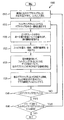
図15は、本原理の一実施形態による、デプスマップの時間フィルタリングを行うための例示的な方法を示す図である。ステップ1510では、時刻tにおけるデプスマップおよび対応するビデオが、入力として得られる。ステップ1515では、フィルタリングされることになるデプスマップの中の一領域が選択される。ステップ1520では、ビデオフレームの中の同一位置の領域についての動作分析が行われ、得られた動作情報が記録される。ステップ1525では、フィルタの重みが(例えば、動作、時間基準等に基づいて)判定される。ステップ1530では、動作情報を用いて、フィルタリングされることになるデプス領域について、他のデプスマップの中の対応する領域が得られる。ステップ1535では、領域が、他のデプスマップにおける対応する領域と一緒に、かつ、判定された重みを用いて、フィルタリングされる。ステップ1540では、現行のデプスマップが完了したか否かが判定される。そうであれば、制御権はステップ1545に渡される。そうでない場合、制御権は、ステップ1515に戻される。ステップ1545では、t=t+1においてフィルタリングすべきデプスマップがもっとあるのか否かが判定される。そうであれば、制御権は、ステップ1510に戻される。そうでない場合、方法は終了する。
FIG. 15 is a diagram illustrating an exemplary method for performing temporal filtering of a depth map, according to one embodiment of the present principles. In
Claims (19)
前記第1のデプス画像の所与の部分について、前記第1のビデオ画像のうちの同一位置のビデオ部分を判定するステップと、
前記第1のビデオ画像のうちの前記同一位置のビデオ部分の第2のビデオ画像に関する動作を示すビデオ動作ベクトルにアクセスするステップと、
前記第2のビデオ画像に対応する第2のデプス画像にアクセスするステップと、
前記第2のデプス画像のデプス部分を、前記第1のデプス画像の前記所与の部分から、前記ビデオ動作ベクトルに基づいて判定するステップと、
前記第1のデプス画像の前記所与の部分を、前記第2のデプス画像の前記デプス部分に基づいて更新するステップと、
を備える、方法。 Accessing a first depth image corresponding to the first video image,
For a given portion of the first depth image, determining a video portion of the same position of said first video image,
And accessing the video motion vector indicating an operation for the second video image in the video portion of the same position of said first video image,
Accessing a second depth image corresponding to the second video image,
The depth portion of the second depth image, from the given portion of the first depth image, and determining, based on the video operation vector,
Updating the given portion of the first depth image based on the depth portion of the second depth image ;
Equipped with a, way.
前記第3のビデオ画像に対応する第3のデプス画像にアクセスするステップと、
前記第3のデプス画像のデプス部分を、前記第1のデプス画像の前記所与の部分から、前記別のビデオ動作ベクトルに基づいて判定するステップと、
をさらに備え、
前記第1のデプス画像の前記所与の部分を更新するステップが、前記第3のデプス画像の前記デプス部分および前記第2のデプス画像の前記デプス部分にさらに基づく、請求項1に記載の方法。 Accessing another video motion vector indicative of motion related to a third video image of the co-located video portion of the first video image;
Accessing a third depth image corresponding to the third video image;
Determining a depth portion of the third depth image from the given portion of the first depth image based on the another video motion vector ;
Further comprising
The method of claim 1, wherein updating the given portion of the first depth image is further based on the depth portion of the third depth image and the depth portion of the second depth image. .
前記第1のデプス画像の所与の部分について、前記第1のビデオ画像のうちの同一位置のビデオ部分を判定するための手段と、
前記第1のビデオ画像のうちの前記同一位置のビデオ部分の第2のビデオ画像に関する動作を示すビデオ動作ベクトルにアクセスするための手段と、
前記第2のビデオ画像に対応する第2のデプス画像にアクセスするための手段と、
前記第2のデプス画像のデプス部分を、前記第1のデプス画像の前記所与の部分から、前記ビデオ動作ベクトルに基づいて判定するための手段と、
前記第1のデプス画像の前記所与の部分を、前記第2のデプス画像の前記デプス部分に基づいて更新するための手段と、
を備える、装置。 Means for accessing a first depth image corresponding to the first video image;
Means for determining a co-located video portion of the first video image for a given portion of the first depth image;
Means for accessing a video motion vector indicative of motion associated with a second video image of the co-located video portion of the first video image;
Means for accessing a second depth image corresponding to the second video image;
Means for determining a depth portion of the second depth image from the given portion of the first depth image based on the video motion vector;
Means for updating the given portion of the first depth image based on the depth portion of the second depth image ;
Comprising a device.
前記第1のデプス画像の所与の部分について、前記第1のビデオ画像のうちの同一位置のビデオ部分を判定するステップと、
前記第1のビデオ画像のうちの前記同一位置のビデオ部分の第2のビデオ画像に関する動作を示すビデオ動作ベクトルにアクセスするステップと、
前記第2のビデオ画像に対応する第2のデプス画像にアクセスするステップと、
前記第2のデプス画像のデプス部分を、前記第1のデプス画像の前記所与の部分から、前記ビデオ動作ベクトルに基づいて判定するステップと、
前記第1のデプス画像の前記所与の部分を、前記第2のデプス画像の前記デプス部分に基づいて更新するステップと、
をプロセッサに少なくとも行わせるための命令を記憶している、プロセッサ可読媒体。 Accessing a first depth image corresponding to the first video image,
For a given portion of the first depth image, determining a video portion of the same position of said first video image,
And accessing the video motion vector indicating an operation for the second video image in the video portion of the same position of said first video image,
Accessing a second depth image corresponding to the second video image,
The depth portion of the second depth image, from the given portion of the first depth image, and determining, based on the video operation vector,
Updating the given portion of the first depth image based on the depth portion of the second depth image ;
The stores instructions for causing at least performed in a processor, the processor-readable medium.
前記第1のデプス画像の所与の部分について、前記第1のビデオ画像のうちの同一位置のビデオ部分を判定するステップと、
前記第1のビデオ画像のうちの前記同一位置のビデオ部分の第2のビデオ画像に関する動作を示すビデオ動作ベクトルにアクセスするステップと、
前記第2のビデオ画像に対応する第2のデプス画像にアクセスするステップと、
前記第2のデプス画像のデプス部分を、前記第1のデプス画像の前記所与の部分から、前記ビデオ動作ベクトルに基づいて判定するステップと、
前記第1のデプス画像の前記所与の部分を、前記第2のデプス画像の前記デプス部分に基づいて更新するステップと、
を少なくとも行うために構成されたプロセッサを備える、装置。 Accessing a first depth image corresponding to the first video image,
For a given portion of the first depth image, determining a video portion of the same position of said first video image,
And accessing the video motion vector indicating an operation for the second video image in the video portion of the same position of said first video image,
Accessing a second depth image corresponding to the second video image,
The depth portion of the second depth image, from the given portion of the first depth image, and determining, based on the video operation vector,
Updating the given portion of the first depth image based on the depth portion of the second depth image ;
The comprises a processor configured to at least perform, device.
前記第1のビデオ画像のうちの同一位置のビデオ部分についてのビデオ動作ベクトルを判定するための動作分析器であって、前記第1のビデオ画像のついての前記同一位置のビデオ部分が第1のデプス画像の所与の部分に対応し、かつ、前記ビデオ動作ベクトルが前記第1のビデオ画像のうちの前記同一位置のビデオ部分の前記第2のビデオ画像に関する動作を示す、動作分析器と、
を備え、
前記時間フィルタが、前記第2のデプス画像のデプス部分を、前記第1のデプス画像の前記所与の部分から、前記ビデオ動作ベクトルに基づいて判定し、かつ、前記時間フィルタが、前記第1のデプス画像の前記所与の部分を、前記第2のデプス画像の前記デプス部分に基づいて更新する、装置。 For accessing the first depth image corresponding to the first video image, and a temporal filter for accessing the second depth image corresponding to the second video image,
A motion analysis device for determining the video motion vectors for the video portion of the same position of said first video image, the video portion of the co-located with the first video image is first A motion analyzer corresponding to a given portion of the depth image, and wherein the video motion vector indicates an operation on the second video image of the co-located video portion of the first video image ;
With
The temporal filter determines a depth portion of the second depth image from the given portion of the first depth image based on the video motion vector, and the temporal filter includes the first depth image; said given portion of the depth image of the updates based on the depth portion of the second depth image, device.
前記第1のビデオ画像のうちの同一位置のビデオ部分についてのビデオ動作ベクトルを判定するための動作分析器であって、前記第1のビデオ画像のついての前記同一位置のビデオ部分が前記第1のデプス画像の所与の部分に対応し、かつ、前記ビデオ動作ベクトルが前記第1のビデオ画像のうちの同一位置のビデオ部分の前記第2のビデオ画像に関する動作を示す、動作分析器と、
を備え、
前記時間フィルタが、前記第2のデプス画像のデプス部分を、前記第1のデプス画像の前記所与の部分から、前記ビデオ動作ベクトルに基づいて判定し、かつ、前記時間フィルタが、前記第1のデプス画像の前記所与の部分を、前記第2のデプス画像の前記デプス部分に基づいて更新し、
前記装置は、前記第1のデプス画像の前記更新された所与の部分を含む信号を変調するための変調器をさらに備える、装置。 For accessing the first depth image corresponding to the first video image, and a temporal filter for accessing the second depth image corresponding to the second video image,
A motion analysis device for determining the video motion vectors for the video portion of the same position of said first video image, the same position of the video portion is the first with the first video image A motion analyzer corresponding to a given portion of the depth image of the first video image, and wherein the video motion vector is indicative of a motion on the second video image of the co-located video portion of the first video image ;
Equipped with a,
The temporal filter determines a depth portion of the second depth image from the given portion of the first depth image based on the video motion vector, and the temporal filter includes the first depth image; Updating the given portion of the depth image of the second depth image based on the depth portion of the second depth image;
The apparatus further comprises a modulator for modulating a signal including the updated given part of the first depth image, device.
前記第1のデプス画像にアクセスするための、かつ、前記第2のデプス画像にアクセスするための一次的フィルタと、
前記第1のビデオ画像のうちの同一位置のビデオ部分についてのビデオ動作ベクトルを判定するための動作分析器であって、前記第1のビデオ画像のついての前記同一位置のビデオ部分が前記第1のデプス画像の所与の部分に対応し、前記ビデオ動作ベクトルが前記第1のビデオ画像のうちの前記同一位置のビデオ部分の前記第2のビデオ画像に関する動作を示す、動作分析器と、
を備え、
前記時間フィルタが、前記第2のデプス画像のデプス部分を、前記第1のデプス画像の前記所与の部分から、前記ビデオ動作ベクトルに基づいて判定し、かつ、前記時間フィルタが、前記第1のデプス画像の前記所与の部分を、前記第2のデプス画像の前記デプス部分に基づいて更新する、装置。 Demodulate a signal including a first video image, a second video image, a first depth image corresponding to the first video image, and a second depth image corresponding to the second video image A demodulator to
And, for accessing the first depth image, a primary filter for accessing the second depth image,
A motion analysis device for determining the video motion vectors for the video portion of the same position of said first video image, the same position of the video portion is the first with the first video image A motion analyzer, corresponding to a given portion of the depth image, wherein the video motion vector indicates an operation on the second video image of the co-located video portion of the first video image ;
With
The temporal filter determines a depth portion of the second depth image from the given portion of the first depth image based on the video motion vector, and the temporal filter includes the first depth image; said given portion of the depth image of the updates based on the depth portion of the second depth image, device.
Applications Claiming Priority (3)
| Application Number | Priority Date | Filing Date | Title |
|---|---|---|---|
| US20649609P | 2009-01-30 | 2009-01-30 | |
| US61/206,496 | 2009-01-30 | ||
| PCT/US2010/000208 WO2010087955A1 (en) | 2009-01-30 | 2010-01-27 | Coding of depth maps |
Publications (3)
| Publication Number | Publication Date |
|---|---|
| JP2012516637A JP2012516637A (en) | 2012-07-19 |
| JP2012516637A5 true JP2012516637A5 (en) | 2013-03-14 |
| JP5792632B2 JP5792632B2 (en) | 2015-10-14 |
Family
ID=42122982
Family Applications (1)
| Application Number | Title | Priority Date | Filing Date |
|---|---|---|---|
| JP2011547971A Expired - Fee Related JP5792632B2 (en) | 2009-01-30 | 2010-01-27 | Depth map encoding |
Country Status (7)
| Country | Link |
|---|---|
| US (1) | US9569819B2 (en) |
| EP (1) | EP2384584B1 (en) |
| JP (1) | JP5792632B2 (en) |
| KR (1) | KR101675555B1 (en) |
| CN (1) | CN102356637B (en) |
| BR (1) | BRPI1007451A2 (en) |
| WO (1) | WO2010087955A1 (en) |
Families Citing this family (27)
| Publication number | Priority date | Publication date | Assignee | Title |
|---|---|---|---|---|
| KR101590767B1 (en) * | 2009-06-09 | 2016-02-03 | 삼성전자주식회사 | Image processing apparatus and method |
| CN102428501A (en) * | 2009-09-18 | 2012-04-25 | 株式会社东芝 | Image processing apparatus |
| WO2011060579A1 (en) * | 2009-11-18 | 2011-05-26 | Industrial Technology Research Institute | Method for generating depth maps from monocular images and systems using the same |
| US20110211749A1 (en) * | 2010-02-28 | 2011-09-01 | Kar Han Tan | System And Method For Processing Video Using Depth Sensor Information |
| WO2012061549A2 (en) * | 2010-11-03 | 2012-05-10 | 3Dmedia Corporation | Methods, systems, and computer program products for creating three-dimensional video sequences |
| JP2014140089A (en) * | 2011-05-10 | 2014-07-31 | Sharp Corp | Image encoding device, image encoding method, image encoding program, image decoding device, image decoding method, and image decoding program |
| US8817073B2 (en) * | 2011-08-12 | 2014-08-26 | Himax Technologies Limited | System and method of processing 3D stereoscopic image |
| KR20170005464A (en) * | 2011-08-30 | 2017-01-13 | 노키아 테크놀로지스 오와이 | An apparatus, a method and a computer program for video coding and decoding |
| US9213883B2 (en) * | 2012-01-10 | 2015-12-15 | Samsung Electronics Co., Ltd. | Method and apparatus for processing depth image |
| KR101896307B1 (en) * | 2012-01-10 | 2018-09-10 | 삼성전자주식회사 | Method and apparatus for processing depth image |
| KR101938205B1 (en) | 2012-03-19 | 2019-01-14 | 한국전자통신연구원 | Method for depth video filtering and apparatus thereof |
| US9286658B2 (en) * | 2012-03-22 | 2016-03-15 | Qualcomm Incorporated | Image enhancement |
| WO2013157439A1 (en) * | 2012-04-17 | 2013-10-24 | ソニー株式会社 | Decoding device, decoding method, coding device, and coding method |
| US9307252B2 (en) | 2012-06-04 | 2016-04-05 | City University Of Hong Kong | View synthesis distortion model for multiview depth video coding |
| JP5830705B2 (en) * | 2012-09-25 | 2015-12-09 | パナソニックIpマネジメント株式会社 | Image signal processing apparatus and image signal processing method |
| US20150379720A1 (en) * | 2013-01-31 | 2015-12-31 | Threevolution Llc | Methods for converting two-dimensional images into three-dimensional images |
| US10080036B2 (en) | 2013-05-16 | 2018-09-18 | City University Of Hong Kong | Method and apparatus for depth video coding using endurable view synthesis distortion |
| US10368097B2 (en) * | 2014-01-07 | 2019-07-30 | Nokia Technologies Oy | Apparatus, a method and a computer program product for coding and decoding chroma components of texture pictures for sample prediction of depth pictures |
| WO2015109598A1 (en) | 2014-01-27 | 2015-07-30 | Mediatek Singapore Pte. Ltd. | Methods for motion parameter hole filling |
| WO2015115946A1 (en) * | 2014-01-30 | 2015-08-06 | Telefonaktiebolaget L M Ericsson (Publ) | Methods for encoding and decoding three-dimensional video content |
| WO2015158570A1 (en) * | 2014-04-17 | 2015-10-22 | Koninklijke Philips N.V. | System, method for computing depth from video |
| US10212408B1 (en) | 2016-06-29 | 2019-02-19 | Amazon Technologies, Inc. | Depth-map augmentation techniques |
| US10237530B1 (en) * | 2016-06-29 | 2019-03-19 | Amazon Technologies, Inc. | Depth-map augmentation techniques |
| EP3358844A1 (en) * | 2017-02-07 | 2018-08-08 | Koninklijke Philips N.V. | Method and apparatus for processing an image property map |
| KR102472767B1 (en) | 2017-09-14 | 2022-12-01 | 삼성전자주식회사 | Method and apparatus of calculating depth map based on reliability |
| US10643336B2 (en) | 2018-03-06 | 2020-05-05 | Sony Corporation | Image processing apparatus and method for object boundary stabilization in an image of a sequence of images |
| CN110400344B (en) * | 2019-07-11 | 2021-06-18 | Oppo广东移动通信有限公司 | Depth map processing method and device |
Family Cites Families (22)
| Publication number | Priority date | Publication date | Assignee | Title |
|---|---|---|---|---|
| JP2001175863A (en) * | 1999-12-21 | 2001-06-29 | Nippon Hoso Kyokai <Nhk> | Method and device for multi-viewpoint image interpolation |
| CN1236628C (en) | 2000-03-14 | 2006-01-11 | 株式会社索夫特4D | Method and device for producing stereo picture |
| US7180663B2 (en) | 2002-06-19 | 2007-02-20 | Robert Bruce Collender | 3D motion picture theatre |
| WO2004014086A1 (en) | 2002-07-31 | 2004-02-12 | Koninklijke Philips Electronics N.V. | Method and apparatus for encoding a digital video signal |
| JP3988879B2 (en) * | 2003-01-24 | 2007-10-10 | 日本電信電話株式会社 | Stereo image generation method, stereo image generation apparatus, stereo image generation program, and recording medium |
| KR100834749B1 (en) | 2004-01-28 | 2008-06-05 | 삼성전자주식회사 | Device and method for playing scalable video streams |
| EP1723800A1 (en) | 2004-03-01 | 2006-11-22 | Koninklijke Philips Electronics N.V. | A video signal encoder, a video signal processor, a video signal distribution system and methods of operation therefor |
| CA2553473A1 (en) * | 2005-07-26 | 2007-01-26 | Wa James Tam | Generating a depth map from a tw0-dimensional source image for stereoscopic and multiview imaging |
| US8879635B2 (en) * | 2005-09-27 | 2014-11-04 | Qualcomm Incorporated | Methods and device for data alignment with time domain boundary |
| US8970680B2 (en) * | 2006-08-01 | 2015-03-03 | Qualcomm Incorporated | Real-time capturing and generating stereo images and videos with a monoscopic low power mobile device |
| KR20090052889A (en) * | 2006-09-04 | 2009-05-26 | 코닌클리케 필립스 일렉트로닉스 엔.브이. | Method for determining a depth map from images, device for determining a depth map |
| US8509313B2 (en) * | 2006-10-10 | 2013-08-13 | Texas Instruments Incorporated | Video error concealment |
| EP2087466B1 (en) * | 2006-11-21 | 2020-06-17 | Koninklijke Philips N.V. | Generation of depth map for an image |
| CN101682794B (en) * | 2007-05-11 | 2012-05-02 | 皇家飞利浦电子股份有限公司 | Method, apparatus and system for processing depth-related information |
| US8411205B2 (en) * | 2007-07-11 | 2013-04-02 | Olympus Corporation | Noise reducing image processing apparatus |
| KR101483660B1 (en) | 2007-07-26 | 2015-01-16 | 코닌클리케 필립스 엔.브이. | Method and apparatus for depth-related information propagation |
| JP2009135686A (en) * | 2007-11-29 | 2009-06-18 | Mitsubishi Electric Corp | Stereoscopic video recording method, stereoscopic video recording medium, stereoscopic video reproducing method, stereoscopic video recording apparatus, and stereoscopic video reproducing apparatus |
| EP2232875A2 (en) * | 2008-01-11 | 2010-09-29 | Thomson Licensing | Video and depth coding |
| WO2009157895A1 (en) * | 2008-06-24 | 2009-12-30 | Thomson Licensing | System and method for depth extraction of images with motion compensation |
| CN101374243B (en) | 2008-07-29 | 2010-06-23 | 宁波大学 | Depth map encoding compression method for 3DTV and FTV system |
| EP2327059B1 (en) * | 2008-10-02 | 2014-08-27 | Fraunhofer-Gesellschaft zur Förderung der angewandten Forschung e.V. | Intermediate view synthesis and multi-view data signal extraction |
| KR101642964B1 (en) * | 2010-11-03 | 2016-07-27 | 삼성전자주식회사 | Apparatus and method for dynamic controlling integration time of depth camera for accuracy enhancement |
-
2010
- 2010-01-27 WO PCT/US2010/000208 patent/WO2010087955A1/en active Application Filing
- 2010-01-27 CN CN201080011941.5A patent/CN102356637B/en active Active
- 2010-01-27 BR BRPI1007451A patent/BRPI1007451A2/en active Search and Examination
- 2010-01-27 US US13/138,205 patent/US9569819B2/en active Active
- 2010-01-27 JP JP2011547971A patent/JP5792632B2/en not_active Expired - Fee Related
- 2010-01-27 KR KR1020117017697A patent/KR101675555B1/en active IP Right Grant
- 2010-01-27 EP EP10703709.5A patent/EP2384584B1/en active Active
Similar Documents
| Publication | Publication Date | Title |
|---|---|---|
| JP2012516637A5 (en) | ||
| JP5792632B2 (en) | Depth map encoding | |
| JP5174117B2 (en) | Method and apparatus for motion compensated frame rate upconversion | |
| JP4653235B2 (en) | Composition of panoramic images using frame selection | |
| US20180098082A1 (en) | Motion estimation using hybrid video imaging system | |
| CN109963048B (en) | Noise reduction method, noise reduction device and noise reduction circuit system | |
| IL257496A (en) | Method and apparatus of motion compensation for video coding based on bi prediction optical flow techniques | |
| JP2010041064A (en) | Image processing unit, image processing method, and program | |
| JP2020522200A (en) | Optical Flow Estimation for Motion Compensated Prediction in Video Coding | |
| JP2009500931A (en) | Digital image processing apparatus, processing method, and computer program product | |
| US11490078B2 (en) | Method and apparatus for deep neural network based inter-frame prediction in video coding | |
| JP2009510906A (en) | Method and apparatus for motion projection error concealment in block-based video | |
| KR101756842B1 (en) | Method and apparatus for image frame interpolation | |
| US20130235931A1 (en) | Masking video artifacts with comfort noise | |
| WO2016131270A1 (en) | Error concealment method and apparatus | |
| JP4824708B2 (en) | Moving picture encoding method, apparatus, program, and computer-readable recording medium | |
| CN102970541B (en) | Image filtering method and device | |
| CN106791642B (en) | Video data recovery method and device | |
| Zhao et al. | A highly effective error concealment method for whole frame loss | |
| JP4915468B2 (en) | Image processing apparatus, image processing method, and program | |
| CN113194313B (en) | Video frame compression and decompression method and device | |
| CN108810317B (en) | True motion estimation method and device, computer readable storage medium and terminal | |
| JP2004531161A (en) | Method and decoder for processing digital video signals | |
| JP2008066911A (en) | Video encoding method, video encoding device, computer readable recording medium recorded with its program | |
| JP2011055245A (en) | Motion vector estimating method and image processing apparatus using the method, image processing method and image processing program |