JP2012514226A - Method and apparatus for producing a film - Google Patents
Method and apparatus for producing a film Download PDFInfo
- Publication number
- JP2012514226A JP2012514226A JP2011544010A JP2011544010A JP2012514226A JP 2012514226 A JP2012514226 A JP 2012514226A JP 2011544010 A JP2011544010 A JP 2011544010A JP 2011544010 A JP2011544010 A JP 2011544010A JP 2012514226 A JP2012514226 A JP 2012514226A
- Authority
- JP
- Japan
- Prior art keywords
- toner
- transport belt
- heat source
- belt
- melting point
- Prior art date
- Legal status (The legal status is an assumption and is not a legal conclusion. Google has not performed a legal analysis and makes no representation as to the accuracy of the status listed.)
- Ceased
Links
Images

Classifications
-
- G—PHYSICS
- G03—PHOTOGRAPHY; CINEMATOGRAPHY; ANALOGOUS TECHNIQUES USING WAVES OTHER THAN OPTICAL WAVES; ELECTROGRAPHY; HOLOGRAPHY
- G03G—ELECTROGRAPHY; ELECTROPHOTOGRAPHY; MAGNETOGRAPHY
- G03G15/00—Apparatus for electrographic processes using a charge pattern
- G03G15/01—Apparatus for electrographic processes using a charge pattern for producing multicoloured copies
- G03G15/0142—Structure of complete machines
- G03G15/0178—Structure of complete machines using more than one reusable electrographic recording member, e.g. one for every monocolour image
- G03G15/0194—Structure of complete machines using more than one reusable electrographic recording member, e.g. one for every monocolour image primary transfer to the final recording medium
-
- G—PHYSICS
- G03—PHOTOGRAPHY; CINEMATOGRAPHY; ANALOGOUS TECHNIQUES USING WAVES OTHER THAN OPTICAL WAVES; ELECTROGRAPHY; HOLOGRAPHY
- G03G—ELECTROGRAPHY; ELECTROPHOTOGRAPHY; MAGNETOGRAPHY
- G03G15/00—Apparatus for electrographic processes using a charge pattern
- G03G15/14—Apparatus for electrographic processes using a charge pattern for transferring a pattern to a second base
- G03G15/16—Apparatus for electrographic processes using a charge pattern for transferring a pattern to a second base of a toner pattern, e.g. a powder pattern, e.g. magnetic transfer
- G03G15/1605—Apparatus for electrographic processes using a charge pattern for transferring a pattern to a second base of a toner pattern, e.g. a powder pattern, e.g. magnetic transfer using at least one intermediate support
- G03G15/161—Apparatus for electrographic processes using a charge pattern for transferring a pattern to a second base of a toner pattern, e.g. a powder pattern, e.g. magnetic transfer using at least one intermediate support with means for handling the intermediate support, e.g. heating, cleaning, coating with a transfer agent
-
- G—PHYSICS
- G03—PHOTOGRAPHY; CINEMATOGRAPHY; ANALOGOUS TECHNIQUES USING WAVES OTHER THAN OPTICAL WAVES; ELECTROGRAPHY; HOLOGRAPHY
- G03G—ELECTROGRAPHY; ELECTROPHOTOGRAPHY; MAGNETOGRAPHY
- G03G2215/00—Apparatus for electrophotographic processes
- G03G2215/00362—Apparatus for electrophotographic processes relating to the copy medium handling
- G03G2215/00443—Copy medium
- G03G2215/00493—Plastic
- G03G2215/00497—Overhead Transparency, i.e. OHP
-
- G—PHYSICS
- G03—PHOTOGRAPHY; CINEMATOGRAPHY; ANALOGOUS TECHNIQUES USING WAVES OTHER THAN OPTICAL WAVES; ELECTROGRAPHY; HOLOGRAPHY
- G03G—ELECTROGRAPHY; ELECTROPHOTOGRAPHY; MAGNETOGRAPHY
- G03G2215/00—Apparatus for electrophotographic processes
- G03G2215/16—Transferring device, details
- G03G2215/1676—Simultaneous toner image transfer and fixing
- G03G2215/1695—Simultaneous toner image transfer and fixing at the second or higher order transfer point
Landscapes
- Physics & Mathematics (AREA)
- General Physics & Mathematics (AREA)
- Fixing For Electrophotography (AREA)
- Combination Of More Than One Step In Electrophotography (AREA)
- Color Electrophotography (AREA)
- Electrostatic Charge, Transfer And Separation In Electrography (AREA)
- Electronic Switches (AREA)
Abstract
本発明は、選択的に多色のフィルムの簡単且つ費用効率的な製造を可能にする方法及び装置に関する。この方法において、フィルムを製造するために、最初にトナーを輸送ベルトに、印刷ユニットを用いて付与し、本質的に不断のトナー層が前記輸送ベルト上に形成されるようにする。次いで、前記輸送ベルト上の前記トナーを、第1の熱源により、前記トナーの融点よりも高い温度に加熱し、次いで、前記トナーの融点よりも低い温度に冷却する。最後に、前記トナーを凝集材料層として前記輸送ベルトから取り外す。本発明の装置は、輸送ベルトと、トナーを前記輸送ベルトに付与するために配置された印刷ユニットと、熱源とを備える。前記輸送ベルトの移動方向において、前記印刷ユニットの下流に、前記熱源が配置されて、前記輸送ベルト上に存在する前記トナーを加熱することができるように、且つ、前記トナーを前記トナーの融点よりも高い温度に加熱する。The present invention relates to a method and apparatus that allows simple and cost-effective production of selectively multicolored films. In this method, to produce a film, toner is first applied to a transport belt using a printing unit so that an essentially continuous toner layer is formed on the transport belt. Next, the toner on the transport belt is heated to a temperature higher than the melting point of the toner by a first heat source, and then cooled to a temperature lower than the melting point of the toner. Finally, the toner is removed from the transport belt as an aggregate material layer. The apparatus of the present invention comprises a transport belt, a printing unit arranged to apply toner to the transport belt, and a heat source. In the moving direction of the transport belt, the heat source is arranged downstream of the printing unit so that the toner existing on the transport belt can be heated, and the toner is removed from the melting point of the toner. Also heat to a higher temperature.
Description
本発明は、フィルムを製造するための方法及び装置に関する。 The present invention relates to a method and apparatus for producing a film.
フィルムを製造するための非常に多くの様々な方法が当分野で知られており、これらのうち、押出及びカレンダリング技術が、代表的な従来の方法である。 A great many different methods for producing films are known in the art, of which extrusion and calendering techniques are typical conventional methods.
一般的に、これらの方法により製造が可能であるのは、白黒フィルム及び透明フィルムのみである。多色フィルム、又は、画像若しくはテキストを有するフィルムを製造するためには、これらのフィルムを最初のフィルム製造ステップの後に印刷しなければならず、これは非常に複雑であり、また、接着の問題を生じることが多い。さらに、原則として、この方法が可能であるのは、付与されたトナー粒子を融着するために通常適用される温度に耐えられる特別なフィルムを用いた場合のみである。 In general, only black and white films and transparent films can be produced by these methods. In order to produce multicolor films, or films with images or text, these films must be printed after the initial film production step, which is very complex and also has adhesion problems Often occurs. Furthermore, in principle, this method is only possible with special films that can withstand the temperatures normally applied to fuse the applied toner particles.
フィルムを製造するための従来の方法及び装置に基づき、本発明の目的は、選択的に多色のフィルムの製造を簡単且つ費用効率的に可能にする方法及び装置を提供することにある。 Based on conventional methods and apparatus for producing films, it is an object of the present invention to provide a method and apparatus that enables the production of selectively multicolored films simply and cost effectively.
本発明によれば、この目的は、請求項1に記載されている方法、及び請求項19に記載されている装置を用いて達成される。本発明のさらなる実施形態は従属請求項から明らかである。
According to the invention, this object is achieved using the method as defined in
詳細には、フィルムを製造するための方法が提供される。この方法において、トナーを輸送ベルトに、少なくとも1つの印刷ユニットを用いて付与し、本質的に不断のトナー層が前記輸送ベルト上に形成されるようにする。次いで、前記輸送ベルト上のトナーが、少なくとも1つの第1の熱源により、前記トナーの融点よりも高い温度に加熱され、次いで、前記トナーの融点よりも低い温度に冷却され、そして、前記輸送ベルトから凝集材料層として取り外される。上記の方法を用いることにより、トナーから直接フィルムを製造することが簡単に可能にされ、これは、特に、多色(及び、必要であればフルカラー)画像フィルムの形成を可能にする。本件において、用語「本質的に不断のトナー層」(an essentially uninterrupted toner layer")とは、トナーを前記トナーの融点よりも高い温度に加熱する時に互いに接触して合体し、それにより凝集材料層を形成するトナー粒子を有するトナー層を意味する。しかし、この層の特定の位置に開口部を設けることも可能である。詳細には、トナー層の特定の位置に開口部を設け、それにより、任意の種類の形状を、トナー層のトリミングを全く必要とせずに複製することが可能である。この方法は、連続的なフィルムウェブを製造すること、そしてまた、トリミングを必要としないシートタイプのフィルム部分を製造することの、簡単且つ費用効率的な方法を可能にする。シートタイプのフィルムは、例えば、トナーをフィルムの形態で、適切なフリースペースが後続フィルムに対して残された状態で付与することにより製造される。 In particular, a method for producing a film is provided. In this method, toner is applied to the transport belt using at least one printing unit so that an essentially continuous toner layer is formed on the transport belt. The toner on the transport belt is then heated by at least one first heat source to a temperature above the melting point of the toner, then cooled to a temperature below the melting point of the toner, and the transport belt Is removed as a coherent material layer. By using the method described above, it is easily possible to produce films directly from toner, which in particular allows the formation of multicolor (and full color if necessary) image films. In this context, the term “an essentially uninterrupted toner layer” means that the toners are brought into contact with each other when heated to a temperature above the melting point of the toner, thereby causing a coherent material layer. However, it is also possible to provide an opening at a specific position of this layer, in particular, by providing an opening at a specific position of the toner layer, thereby Any type of shape can be replicated without requiring any trimming of the toner layer.This method produces a continuous film web, and also a sheet type that does not require trimming. A sheet-type film, for example, a toner in the form of a film, with a suitable freespread, is possible. In the state that it is left on the subsequent film.
本発明の好ましい実施形態によれば、前記トナーのポリマー鎖が、前記トナーが前記フィルムの安定性をさらに増大するために溶融されているときに架橋される。これを行うために、熱架橋トナーが、前記トナーの前記融点よりも高い温度に、少なくとも1秒間、好ましくは、1秒〜10秒間維持される。或いは、又は、さらに、紫外線架橋トナーに紫外線を、前記トナーが前記トナーの前記融点よりも高い温度を有しているときに照射することも可能である。 According to a preferred embodiment of the present invention, the polymer chains of the toner are crosslinked when the toner is melted to further increase the stability of the film. To do this, the thermally crosslinked toner is maintained at a temperature above the melting point of the toner for at least 1 second, preferably 1 second to 10 seconds. Alternatively, or in addition, it is possible to irradiate the ultraviolet crosslinked toner with ultraviolet rays when the toner has a temperature higher than the melting point of the toner.
好ましくは、少なくとも第2の熱源が、前記トナーの温度を予め特定された時間にわたり前記トナーの前記融点よりも高い温度に維持するために設けられる。好ましくは、前記トナーは、前記トナーと接触していない熱源により加熱され、且つ/又は、前記融点よりも高い温度に維持される。非常に急速な非接触加熱のために、特には、マイクロ波アプリケータを熱源として設けることが可能である。前記トナーの温度を維持するために、特には、赤外線源を第2の熱源として設けることが可能である。また、本質的に閉鎖されているオーブンチャンバを熱源として設けることも可能であり、この場合、トナーが付与された前記輸送ベルトが前記オーブンチャンバを通って移動される。或いは、ホットエアを前記トナーに向けさせる熱源を用いることも考えられる。 Preferably, at least a second heat source is provided to maintain the temperature of the toner at a temperature above the melting point of the toner for a prespecified time. Preferably, the toner is heated by a heat source not in contact with the toner and / or maintained at a temperature higher than the melting point. For very rapid non-contact heating, it is possible in particular to provide a microwave applicator as a heat source. In order to maintain the temperature of the toner, in particular, an infrared source can be provided as the second heat source. It is also possible to provide an oven chamber that is essentially closed as a heat source, in which case the transport belt, to which toner has been applied, is moved through the oven chamber. Alternatively, it is conceivable to use a heat source that directs hot air to the toner.
本発明の一実施形態において、前記トナーは、冷却されているときに、前記輸送ベルトの片面と、前記輸送ベルトに対向する循環ベルトとの間に挟まれる。このように2つのベルトの間に挟むことにより、画定された面構造でのフィルム形成が可能になる。好ましくは、前記トナーは、加熱されているときにも前記輸送ベルトの片面と前記循環ベルトとの間に挟まれる。 In one embodiment of the present invention, when the toner is cooled, the toner is sandwiched between one surface of the transport belt and a circulation belt facing the transport belt. In this manner, the film can be formed with a defined surface structure by being sandwiched between the two belts. Preferably, the toner is sandwiched between one surface of the transport belt and the circulation belt even when heated.
本発明の特に好ましい実施形態によれば、複数の印刷ユニットが異なるトナーを前記輸送ベルトに付与し、これにより、多色フィルム(必要であれば、パターン又は任意の画像も施される)を形成することを可能にする。これを行うために、異なる色を有するトナーが付与されることが好ましい。好ましくは、少なくとも1つの無色のトナーが、本質的に不断の無色トナー層が形成されるように付与される。この無色トナー層は、例えば、連続的な支持層又は接着層として機能し得る。そして、異なる色のトナーが、必要に応じて、例えば画像及び構造を形成するために用いられ得る。好ましくは、前記無色のトナーは、用いられている他のトナーの平均粒径よりも大きい平均粒径を有し、それにより、前記トナー粒子の溶融堆積後に十分に安定した溶融トナー層をもたらす。 According to a particularly preferred embodiment of the present invention, a plurality of printing units apply different toners to the transport belt, thereby forming a multicolor film (with a pattern or any image if necessary). Make it possible to do. To do this, it is preferred that toners with different colors are applied. Preferably, at least one colorless toner is applied such that an essentially constant colorless toner layer is formed. This colorless toner layer can function, for example, as a continuous support layer or adhesive layer. Different color toners can then be used as needed to form, for example, images and structures. Preferably, the colorless toner has an average particle size that is greater than the average particle size of the other toners used, thereby providing a sufficiently stable molten toner layer after melt deposition of the toner particles.
本発明の好ましい実施形態において、トナーが前記輸送ベルトに、電子写真印刷方法により付与される。 In a preferred embodiment of the present invention, toner is applied to the transport belt by an electrophotographic printing method.
また、本発明の目的は、フィルムを製造するための装置により達成される。前記装置は、輸送ベルトと、トナーを付与するために前記輸送ベルト上に配置された少なくとも1つの印刷ユニットと、前記輸送ベルトの移動方向において前記少なくとも1つの印刷ユニットの下流に、前記輸送ベルト上に存在するトナーを加熱することができるように配置された少なくとも1つの熱源とを備える。前記熱源は、前記トナーを前記トナーの融点よりも高い温度に加熱することに適している。このような装置は、先に述べた方法によりトナーから直接フィルムを製造することを可能にし、従って、前記方法と同一の利点ももたらす。 The object of the present invention is also achieved by an apparatus for producing a film. The apparatus includes a transport belt, at least one printing unit disposed on the transport belt for applying toner, and on the transport belt downstream of the at least one printing unit in a direction of movement of the transport belt. And at least one heat source arranged to be able to heat the toner present. The heat source is suitable for heating the toner to a temperature higher than the melting point of the toner. Such an apparatus makes it possible to produce a film directly from toner by the method described above, and therefore also provides the same advantages as the method described above.
好ましくは、少なくとも1つの冷却ユニットが、前記輸送ベルトの移動方向において前記少なくとも1つの熱源の下流に、前記輸送ベルト上に存在するトナーを冷却することができるように配置されて設けられ、前記冷却ユニットは、前記トナーを前記トナーの前記融点よりも低い温度に冷却することに適している。好ましくは、前記輸送ベルトの輸送速度及び/又は前記熱源を制御するための少なくとも1つの制御ユニットが、前記トナーの適切な溶融堆積を保証するために設けられる。一実施形態において、少なくとも1つの紫外線源が、紫外線を前記輸送ベルトの前記少なくとも1つの熱源の領域内に向けさせ、それにより前記トナーの溶融状態での紫外線架橋が可能であるように設けられる。 Preferably, at least one cooling unit is disposed and provided downstream of the at least one heat source in the moving direction of the transport belt so as to cool toner existing on the transport belt, and the cooling The unit is suitable for cooling the toner to a temperature lower than the melting point of the toner. Preferably, at least one control unit for controlling the transport speed of the transport belt and / or the heat source is provided to ensure proper melt deposition of the toner. In one embodiment, at least one UV source is provided to direct UV light into the region of the at least one heat source of the transport belt, thereby enabling UV crosslinking in the molten state of the toner.
また、前記輸送ベルトの移動方向において前記少なくとも1つの第1の熱源の下流に配置され、且つ前記トナーを前記トナーの前記融点よりも高い温度に維持するのに適した第2の熱源を設けることも可能である。前記第2の熱源は、特には、熱架橋トナーに対して、前記トナーが所定の時間にわたりトナーの溶融温度よりも高い温度に維持されることを可能にする。好ましくは、少なくとも1つの熱源が、前記トナーを、前記トナーの構造と、従って前記トナーにより形成される画像又はパターンとを損なわないように非接触式に加熱するのに適している。適切な熱源は、特には、マイクロ波アプリケータ、赤外線源、赤外線成分及び紫外線成分を有する(前記赤外線成分及び前記紫外線成分の両方が少なくとも20%である)照射線源、本質的に閉鎖されているオーブンチャンバ、及び/又はホットエア源である。或いは、前記熱源として、互いに対して付勢された2つのローラを設けることも可能であり、前記ローラの少なくとも一方が、対応する加熱装置を介して加熱可能であり、前記輸送ベルトが前記ローラ間のニップを通過される。印刷技術において、このようなローラが、画像を支持基板に融着させるものとして知られている。本発明の一実施形態によれば、循環ベルトが設けられ、前記ベルトは、前記輸送ベルトに、前記少なくとも1つの熱源及び前記少なくとも1つの冷却ユニットの少なくとも有効領域を覆う領域に沿って接触する。先に述べたように、このような追加の循環ベルトは、画定された面構造をフィルム上に形成することを可能にする。前記第1の熱源が、対向して配置された2つのローラを有する場合、前記ローラの一方が、好ましくは、前記循環ベルトのための偏向ローラである。 A second heat source disposed downstream of the at least one first heat source in the moving direction of the transport belt and suitable for maintaining the toner at a temperature higher than the melting point of the toner; Is also possible. The second heat source, particularly for thermally cross-linked toners, allows the toner to be maintained at a temperature above the melting temperature of the toner for a predetermined time. Preferably, at least one heat source is suitable for heating the toner in a non-contact manner so as not to damage the structure of the toner and thus the image or pattern formed by the toner. Suitable heat sources are in particular essentially closed, microwave applicators, infrared sources, radiation sources with infrared and ultraviolet components (both the infrared and ultraviolet components are at least 20%). Oven chamber and / or hot air source. Alternatively, it is also possible to provide two rollers biased with respect to each other as the heat source, at least one of the rollers can be heated via a corresponding heating device, and the transport belt is between the rollers Passed through the nip. In printing technology, such rollers are known for fusing images to a support substrate. According to an embodiment of the invention, a circulation belt is provided, said belt being in contact with said transport belt along a region covering at least an effective area of said at least one heat source and said at least one cooling unit. As previously mentioned, such additional circulating belts allow a defined surface structure to be formed on the film. When the first heat source has two rollers arranged opposite to each other, one of the rollers is preferably a deflection roller for the circulation belt.
有利には、前記循環ベルト及び/又は前記輸送ベルトは、グロッサベルトとして設計されて、高光沢性フィルムを製造することを可能にする。グロッサベルトは、印刷技術にて知られているように、非常に低い表面粗度を示すベルトである。好ましくは、前記循環ベルト及び/又は前記輸送ベルトが粘着防止材料から成り、又は粘着防止材料のような材料によりコーティングされ、それにより、前記フィルムを良好に取り外すことを可能にする。これを達成するために、前記循環ベルト及び/又は前記輸送ベルトは、例えば、ポリイミド材料から成り、又はポリイミド材料のような材料によりコーティングされる。 Advantageously, the circulation belt and / or the transport belt are designed as glosser belts, making it possible to produce high gloss films. A glosser belt is a belt that exhibits a very low surface roughness, as is known in the printing art. Preferably, the circulation belt and / or the transport belt are made of an anti-stick material or coated with a material such as an anti-stick material, thereby allowing the film to be removed well. In order to achieve this, the circulation belt and / or the transport belt are made of, for example, a polyimide material or coated with a material such as a polyimide material.
割れ目が可能な限り少ない連続フィルムウェブを製造するために、前記循環ベルト及び/又は前記輸送ベルトは、好ましくはシームレス(継ぎ目無し)のウェブ材料から成る。或いは、前記循環ベルト及び/又は前記輸送ベルトは、継ぎ目が形成された場合においても前記継ぎ目が画像化されないように、本質的に平坦な外面を有し得る。前記輸送ベルト上の前記トナーへの直接の照射を可能にするために、前記循環ベルト及び/又は前記輸送ベルトは、本発明の一実施形態において透明な材料から成る。 In order to produce a continuous film web with as few cracks as possible, the circulating belt and / or the transport belt are preferably made of a seamless (seamless) web material. Alternatively, the circulation belt and / or the transport belt may have an essentially flat outer surface so that the seam is not imaged when the seam is formed. In order to allow direct irradiation of the toner on the transport belt, the circulation belt and / or the transport belt are made of a transparent material in one embodiment of the present invention.
本発明の特に好ましい実施形態は、異なるトナーを前記輸送ベルト上に付与するための複数の印刷ユニットを有し、これにより、例えば、多色画像、特にはフルカラー画像、又は、パターンを有する構造を形成することができる。この実施形態において、好ましくは、少なくとも1つの印刷ユニットが、本質的に不断のトナーカバーを前記輸送ベルト上に設けることができ、前記トナーカバーは、例えば、粘着性支持体又は接着層として機能する。好ましくは、少なくとも1つの印刷ユニットが電子写真印刷ユニットである。本発明の別の実施形態が、前記輸送ベルト及び/又は前記循環ベルトをクリーニングするための少なくとも1つのクリーニング装置を提供する。 Particularly preferred embodiments of the present invention have a plurality of printing units for applying different toners onto the transport belt, so that, for example, a structure having a multicolor image, in particular a full color image, or a pattern. Can be formed. In this embodiment, preferably at least one printing unit can be provided with an essentially continuous toner cover on the transport belt, the toner cover functioning as, for example, an adhesive support or an adhesive layer . Preferably, at least one printing unit is an electrophotographic printing unit. Another embodiment of the present invention provides at least one cleaning device for cleaning the transport belt and / or the circulation belt.
以下に、本発明を、図面を参照しつつ、より詳細に説明する。 Hereinafter, the present invention will be described in more detail with reference to the drawings.
以下の説明において、位置及び/又は方向に関する情報は、図面に示された内容に関連しているが、本出願を限定するためのものでは全くない。 In the following description, the information regarding the position and / or direction is related to the contents shown in the drawings, but is not intended to limit the present application at all.
図1は、フィルム3を製造するための装置1の概略側面図である。装置1は、複数の印刷ユニット5、輸送ユニット7、クリーニングユニット9、冷却ユニット10、融着ユニット12、及びトレイ14を備える。
FIG. 1 is a schematic side view of an
図1によれば、フィルム3がシート(枚葉)の形態で示されており、トレイ14上にフィルムシートスタックとして置かれている。前記トレイは、二重矢印Aにより示されているように高さ調節可能である。しかし、後にさらに詳細に説明するように、連続フィルムを装置1により製造し、次いで、この連続フィルムを、例えばロール上に巻き取ることも可能である。
According to FIG. 1, the film 3 is shown in the form of sheets (sheets) and is placed on the tray 14 as a film sheet stack. The tray is adjustable in height as indicated by the double arrow A. However, as will be explained in more detail later, it is also possible to produce a continuous film with the
図示されている装置1は5つの印刷ユニット5を示し、印刷ユニット5は、例えば、黒色、シアン、マゼンタ、黄色、及び、透明なトナーと共に動作されることができる。当業者に明らかであるように、もちろん、異なる色のトナーと共に動作する別の個数の印刷ユニットを設けることも可能である。
The
印刷ユニット5は電子写真印刷ユニットとして示されており、各々が、イメージング(画像形成)シリンダ16を含む。イメージングシリンダ16は、図示されているように、輸送ユニット7に直接接触している。もちろん、イメージングシリンダ16と輸送ユニット7との間の中間シリンダも設けられ得る。イメージングシリンダ16の各々が、輸送ユニット7より上に配置され、且つ、前記輸送ユニットにより回転方向に駆動される。これに関しては、以下に、より詳細に説明する。イメージングシリンダ16の各々が、対向して配置された圧力ローラ17に関連付けられている。このような印刷ユニット5の多数が当分野にて既に知られているため、詳細には説明しない。
The printing units 5 are shown as electrophotographic printing units, each including an
輸送ユニット7は、本質的に輸送ベルト18から成り、輸送ベルト18は、閉じた移動経路をもたらすように適切なガイドローラ又は駆動ローラ19の周りにガイドされている。輸送ベルト18は、それぞれの印刷ユニット5のイメージングシリンダ16と圧力ローラ17との間のニップを通過する。輸送ベルト18は、イメージングシリンダ16及び圧力ローラ17と直接摩擦係合し、これにより、輸送ベルトが回転されているときにイメージングシリンダ16及び圧力ローラ17を回転させる。中間シリンダが設けられる場合、このシリンダが輸送ベルト18及びイメージングシリンダ16と摩擦係合することになり、従って、前記シリンダは、間接的にではあるがなお輸送ベルト18により駆動される。
The transport unit 7 consists essentially of a
好ましくは、輸送ベルト18は粘着防止材料から成り、又は粘着防止材料のような材料によりコーティングされる。このような材料の明らかな例は、例えばポリイミド材料である。輸送ベルト18は、好ましくはシームレス(継ぎ目無し)ベルト材料から成り、或いは、継ぎ目が設けられているならば、少なくとも1つの本質的に平坦な外面を有する。また、輸送ベルトは、融着ユニット12内部の温度により損傷されない材料から成るべきであり、また、透明でもあるべきである。輸送ベルト18の外面は、印刷技術において周知のように、いわゆるグロッサベルト(glosser belt)、すなわち、低表面粗度を示すベルトとして構成され、それにより、高光沢性をトナー像にもたらす。
Preferably, the
図示されていないが、回転エンコーダが、それぞれのイメージングシリンダ16上に、及び、輸送シリンダ及び/又はガイドシリンダ19の少なくとも1つの上に、前記要素のそれぞれの回転位置を検出するために設けられ得る。これは、既知の方法での、印刷ユニット5による異なる色分解画像の完全位置合わせ(register perfect)印刷を可能にする。この目的のために、及び、キャリブレーションのために、装置1は、レジスタセンサ(図示せず)も含み得る。レジスタセンサは電子写真印刷機にて一般的であり、また、例えば、本出願の出願人に帰する、公開前でないDE 10 2008 052 397に既に記載されている。
Although not shown, a rotary encoder may be provided on each
クリーニングユニット9が、輸送ベルト18の循環方向(矢印Bを参照)にて印刷ユニット5及び融着ユニット12の下流に配置されているのが見られる。クリーニングユニット9は、輸送ベルト18をクリーニングするための適切な手段(例えば、回転ブラシ及び/又は不動ストリッパ)を含む。
It can be seen that the
冷却ユニット10が、輸送ベルト18の循環方向にて、クリーニングユニット9の下流の、且つ印刷ユニット5の上流に配置されているのも見られる。冷却ユニット10は、冷気を、例えば輸送ベルト18の内面又は外面に向けさせ、これにより、前記ベルトを予め特定された温度にすることが可能である。
It can also be seen that the cooling
融着ユニット12が印刷ユニット5とクリーニングユニット9との間に配置されている。また、融着ユニット12は、輸送ベルト18が前記融着ユニットを通って延在するように配置されている。少なくとも1つの熱源が融着ユニット12内に設けられており、前記熱源は、輸送ベルト18上のトナーをトナーの溶融温度よりも高い温度に加熱することができる。絶対に必須ではないが、この熱源は、好ましくは、トナーを非接触式に加熱することができる熱源であり、例えば、マイクロ波源、赤外線源、ホットエア源、適切な加熱要素を有する本質的に閉鎖されたオーブンチャンバなどによる熱源である。また、用いられるトナーに応じて、融着ユニット12内に紫外線源を設けることも可能であり、前記紫外線源は、輸送ベルト18、及び、輸送ベルト18上に付与されたトナーに紫外線を向けることができるように配置される。これを達成するために、赤外線成分の他に紫外線成分を有する照射線源が設けられることが可能であり、赤外線成分及び紫外線成分の両方が少なくとも20%であるべきである。
A fusing
もちろん、輸送ベルト18に接触する熱源を設けることも可能であり、前記熱源は、互いに対して作用する2つのローラを含み、例えば、前記ローラの少なくとも一方が加熱される。このような融着ローラは印刷技術において公知である。好ましくは、第2の熱源(詳細に示さず)が融着ユニット内に設けられ、前記熱源は、輸送ベルト18上に存在するトナーをトナーの融点よりも高い温度に、長時間(好ましくは1秒〜10秒、又はそれよりも長時間)にわたり維持することができるように配置される。第2の熱源は、第1の熱源と同一のタイプの熱源であっても、或いは、異なるタイプの熱源であってもよいが、原則として第1の熱源ほど多くのエネルギーをもたらす(couple in)必要がない。なぜなら、特定の温度の維持のみが必要であり、融点温度を超える温度への加熱は必要ないからである。
Of course, it is also possible to provide a heat source in contact with the
融着装置12内に、又は、輸送ベルト18の循環方向にて融着ユニット12の末端領域に、若しくはさらに下流に、さらなる冷却ユニット(詳細に示さず)が、輸送ベルト18上に存在するトナーをトナーの融点よりも低い温度に冷却するために設けられ得る。
There is a further cooling unit (not shown in detail) in the
以下に、装置1の動作をより詳細に説明する。最初に、輸送ベルト18が循環方向Bにて動作される。次いで、輸送ベルト18の循環方向Bにて上流に見られる4つの印刷ユニット5が、各トナー画像の完全に位置合わせされた異なる色分解画像を輸送ベルト18上に印刷するために用いられ、この印刷により、様々な(必要に応じて不完全な)輸送ベルト18上のトナーカバーがもたらされ得る。輸送ベルト18の循環方向Bにおける最後の印刷ユニット5が、透明トナーを、本質的に不断のトナー層が輸送ベルト18の上に形成されるように輸送ベルト18に付与する。本文中、「本質的に不断の」(essentially uninterrupted)とは、隣り合うトナー粒子が、溶融されたときに凝集層を形成するように互いに接触している状態を示すための用語である。しかしまた、「本質的に不断の」(essentially uninterrupted)とは、1つの印刷画像内又は隣り合う印刷画像間に、自由空間が、特定の形状を形成するように特定的に設けられる状況を含むことも意味する。シートタイプのフィルム3の製造を示すための図1において、シート印刷にて一般的であるように、互いに距離を有する印刷画像を形成することが可能である。また、このような場合、輸送ベルトがシームレス(継ぎ目無し)であることは必須ではない。なぜなら、輸送ベルト18が、輸送ベルト18の継ぎ目の周辺領域が印刷から除外されるように印刷され得るからである。しかし、例えば、連続フィルムが印刷される場合には(これは、トナーを印刷ユニット5により連続的に付与することにより達成される)、輸送ベルト18が継ぎ目を有さないことが有利であろう。なぜなら、前記継ぎ目がフィルム内で画像として形成される可能性があるからである。
Below, operation | movement of the
トナーが上記の方法で輸送ベルト18に付与された後、トナーがその上に存在する輸送ベルト18は融着ユニット12を通過する。融着ユニット12内部で、少なくとも第1の熱源が、トナーを、トナーの融点よりも高い温度に加熱し、次いで、第2の熱源が、融点よりも高い温度を、予め特定された時間(例えば1秒〜10秒)にわたって維持する。このプロセス中に、個々のトナー粒子が溶融し、凝集トナー層を形成する。このトナー層は、トナーの融点よりも低い温度に冷却されると、フィルム3の形態の凝集層として輸送ベルト18から取り外され得る。熱架橋トナーが用いられる場合、トナーのポリマー鎖の架橋反応が生じ、これにより、フィルム3の安定性が増大する。トナーが紫外線架橋要素を含む場合、好ましくは、紫外線がトナーに融着ユニット12の内部にて照射され、これにより、さらなる架橋と、従って、フィルム3の安定性の増大とがもたらされる。この場合、紫外線はトナー内に、トナーがその融点よりも高い温度に加熱されているときに導入される。
After the toner is applied to the
次いで、トナーは、融着ユニット内で、又は融着ユニットの下流にて、前記トナーの融点よりも低い温度に、能動的又は受動的に冷却される。これは、その後にトナーがフィルム3として輸送ベルト18から取り外されるためである。トナーの能動的冷却が好ましい。しかし、適切な輸送距離にわたる、輸送ベルト18により覆われた受動的な冷却を行うことも可能である。能動的冷却のために、例えば、冷気をトナー層の上面及び/又は輸送ベルト18の裏面に向けることが可能である。もちろん、他の冷却機構も考えられる。例えば、輸送ベルト18が1以上の冷却されたローラの上を移動してもよく、或いは、トナーと直接接触する1以上の冷却されたローラを設けることも可能である。当業者に明らかであるように、トナーをトナーの融点よりも低温に冷却し、それにより、その後トナーをフィルム3として輸送ベルト18から取り外すことを可能にする非常に多様な可能性が存在する。
The toner is then actively or passively cooled in the fusing unit or downstream of the fusing unit to a temperature below the melting point of the toner. This is because the toner is subsequently removed from the
当業者にはさらに明らかであるように、上記の方法は、支持材料を用いずにトナーフィルムを製造することを可能にする。すなわち、フィルムはトナー粒子のみから成る。さらに、上記の方法は、任意の着色(フルカラー画像も含む)、及び任意の形態でのフィルムの製造を可能にする。 As will be further apparent to those skilled in the art, the method described above makes it possible to produce a toner film without the use of a support material. That is, the film consists only of toner particles. Furthermore, the above method allows for the production of films in any color (including full color images) and in any form.
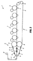
図2は、連続フィルム3の製造を示す、別の装置1の概略側面図である。図2に示されている図において、図1と同一の又は類似の要素が設けられている場合、同一の参照番号が用いられている。
FIG. 2 is a schematic side view of another
図2の装置1も、複数の印刷ユニット5、輸送ユニット7、クリーニングユニット9、冷却ユニット10、及び融着ユニット12を有する。図2においては、高さ調節可能なトレイ14の代わりに、連続フィルム3のための巻取ローラ24を用いる。もちろん、この装置においても、装置1がシートタイプのフィルム3の製造を目的とする場合には、高さ調節可能なトレイ14を設けることも可能であろう。
2 also includes a plurality of printing units 5, a transport unit 7, a
この装置においても、イメージングシリンダ16を有する電子写真タイプの5つの印刷ユニット5が示されている。前記印刷ユニットは、この装置においても圧力ローラ17に関連付けられている。
Also in this apparatus, five electrophotographic type printing units 5 having an
また、輸送ユニット7は、本質的に、複数のガイドローラ及び/又は駆動ローラ19を通って循環するようにガイドされる輸送ベルト18を含む上記の輸送ユニットと同一の方法で構成されている。この装置においても、輸送ベルト18は、それぞれの印刷ユニット15のイメージングシリンダ16と、関連する圧力ローラ17との間の対応するニップを通って延在する。詳細には、この実施形態において、輸送ベルトは、継ぎ目のない輸送ベルト18であり、例えば、ポリイミド材料からつくられる。或いは、継ぎ目が、フィルム3内では全く又はほとんど形成されない程十分に平坦であってもよい。しかし、継ぎ目を、フィルム3を前記継ぎ目の範囲内の寸法にカットするためのカッティングエッジの目標として用いて、例えば、輸送ベルト18の長さに対応するフィルム3のカッティングを可能にすることもできよう。循環ベルト30が融着ユニット12の領域に設けられており、前記ベルトは輸送ベルト18の外面の1つに接触している。トナーが輸送ベルト18上に存在する場合、前記トナーは、融着ユニット12の領域にて、輸送ベルト18とベルト30との間に挟まれる。
Also, the transport unit 7 is essentially configured in the same manner as the transport unit described above including the
ベルト30は、輸送ベルト30を輸送ベルト18の速度で循環させるように駆動する第1のローラ32及び第2のローラ34(好ましくは、ローラ32,34のうちの少なくとも一方)の周りを循環するようにガイドされる。
The
或いは、輸送ベルト30は、輸送ベルト18との摩擦係合により移動されることも可能である。ベルト30はシームレス(継ぎ目無し)ベルトであり、グロッサベルトとして低表面粗度を示す。詳細には、ベルト30は、輸送ベルト18と同一の材料から成り得る。ローラ32は、好ましくは加熱ローラであり、ローラ32の下に配置された、輸送ユニット7の一部であり得るローラ36に押し付けられる。ローラ32,36の一方が加熱されて、輸送ベルト18上に存在するトナーを、ローラの温度により(及び、随意にはローラ間の圧力により)、トナーの溶融温度よりも高い温度に急速に加熱する。これとは反対に、ローラ19又はローラ34の一方が、例えば冷却ローラとして構成されることができ、これにより、輸送ベルト18上に存在するトナーを、前記トナーの融点よりも低い温度に冷却する。
Alternatively, the
さらに、クリーニングユニット39及び冷却ユニット40が輸送ベルト30の領域に設けられており、これらのユニットは、輸送ベルト18のためのクリーニングユニット9及び冷却ユニット10に対応している。さらに、輸送ベルト18とベルト30とが互いに接触している領域に熱源42が設けられており、前記熱源は、先に記載したタイプの熱源である。この熱源は、輸送ベルト18とベルト30との間に受け入れられたトナーを前記トナーの融点よりも高い温度に加熱し、又は、前記温度を特定の時間にわたり維持することができる。これを達成するために、熱源42は、任意の適切なタイプの熱源であり得る。さらに、輸送ベルト18とベルト30とが互いに接触している領域に冷却ユニット44が設けられている。冷却ユニット44は、例えば、冷却空気をそれぞれのベルトに向けさせ、それにより、輸送ベルト18とベルト30との間に存在するトナー層を、特には、前記トナー層の融点よりも低い温度に冷却する。
Further, a cleaning unit 39 and a cooling unit 40 are provided in the region of the
図2に記載されている装置1の動作は、先に記載した装置の動作と本質的に同一であるが、印刷ユニット5は、本質的に、トナー材料の連続層を循環輸送ベルト18上に形成する。次いで、この連続層が融着ユニット12内で溶融堆積され、適切であれば、架橋反応により架橋される。融着ユニット12内のトナーは、冷却ユニット44を用いて、トナーの融点よりも低い温度に冷却される。そして、このようにして製造された連続フィルムの形態の凝集トナー層が融着ユニット12の領域から移動され、巻き取りローラ24により巻き取られる。
The operation of the
以上に記載したように、本発明は、支持材料を用いずにトナーから直接フィルムを製造すること可能にする。本発明を、本発明の好ましい実施形態に関して記載してきたが、本発明は、具体的に例示された実施形態に限定されない。詳細には、異なる実施形態の異なる要素を互いに組み合わせること又は交換することが可能である。詳細には、用いられる印刷ユニットの個数は、当然、例示された個数と異なり得る。印刷ユニット5が、少なくとも一緒に、又は個々にでも、本質的に不断のトナー層を形成することができることが非常に重要である。好ましくは、少なくとも1つの印刷ユニットが、本質的に完全なトナー層を、例えば、透明トナーにより形成することが可能であるべきである。 As described above, the present invention makes it possible to produce a film directly from toner without the use of a support material. Although the present invention has been described in terms of preferred embodiments of the invention, the invention is not limited to the specifically illustrated embodiments. In particular, different elements of different embodiments can be combined or exchanged with each other. In particular, the number of printing units used can of course differ from the exemplified number. It is very important that the printing unit 5 can form an essentially continuous toner layer, at least together or even individually. Preferably, at least one printing unit should be able to form an essentially complete toner layer, for example with transparent toner.
Claims (41)
トナーを輸送ベルトに、少なくとも1つの印刷ユニットを用いて付与し、本質的に不断のトナー層が前記輸送ベルト上に形成されるようにするステップと、
前記輸送ベルト上の前記トナーを、少なくとも第1の熱源により、前記トナーの融点よりも高い温度に加熱するステップと、
前記トナーを、前記トナーの融点よりも低い温度に冷却するステップと、
前記トナーを凝集材料層として前記輸送ベルトから取り外すステップとを含む方法。 A method for producing a film comprising:
Applying toner to the transport belt using at least one printing unit so that an essentially continuous toner layer is formed on the transport belt;
Heating the toner on the transport belt to a temperature higher than the melting point of the toner by at least a first heat source;
Cooling the toner to a temperature below the melting point of the toner;
Removing the toner from the transport belt as an agglomerated material layer.
トナーを輸送ベルトに付与するために配置された少なくとも1つの印刷ユニットと、
前記輸送ベルトの移動方向において前記少なくとも1つの印刷ユニットの下流に、前記輸送ベルト上に存在するトナーを加熱することができるように配置された少なくとも第1の熱源と、を備え、
前記熱源が前記トナーを前記トナーの融点よりも高い温度に加熱することに適している装置。 An apparatus for producing a film,
At least one printing unit arranged to apply toner to the transport belt;
And at least a first heat source disposed downstream of the at least one printing unit in the moving direction of the transport belt so as to be able to heat the toner present on the transport belt,
An apparatus suitable for heating the toner to a temperature higher than the melting point of the toner.
Applications Claiming Priority (3)
| Application Number | Priority Date | Filing Date | Title |
|---|---|---|---|
| DE102008063319.4 | 2008-12-30 | ||
| DE102008063319A DE102008063319A1 (en) | 2008-12-30 | 2008-12-30 | Method and device for producing a film |
| PCT/EP2009/066076 WO2010076108A1 (en) | 2008-12-30 | 2009-11-30 | Method and device for the production of a film |
Publications (2)
| Publication Number | Publication Date |
|---|---|
| JP2012514226A true JP2012514226A (en) | 2012-06-21 |
| JP2012514226A5 JP2012514226A5 (en) | 2012-12-20 |
Family
ID=41692806
Family Applications (1)
| Application Number | Title | Priority Date | Filing Date |
|---|---|---|---|
| JP2011544010A Ceased JP2012514226A (en) | 2008-12-30 | 2009-11-30 | Method and apparatus for producing a film |
Country Status (6)
| Country | Link |
|---|---|
| US (1) | US20110311908A1 (en) |
| EP (1) | EP2370861B1 (en) |
| JP (1) | JP2012514226A (en) |
| CN (1) | CN102246102A (en) |
| DE (1) | DE102008063319A1 (en) |
| WO (1) | WO2010076108A1 (en) |
Families Citing this family (6)
| Publication number | Priority date | Publication date | Assignee | Title |
|---|---|---|---|---|
| US20110103889A1 (en) * | 2009-11-04 | 2011-05-05 | Blakefield Ward S | Soil stabilization blend and method of soil stabilization |
| DE102009058960A1 (en) * | 2009-12-18 | 2011-06-22 | Eastman Kodak Co., N.Y. | Apparatus and method for applying and fixing a toner image on a substrate |
| JP2015064417A (en) * | 2013-09-24 | 2015-04-09 | 村田機械株式会社 | Image forming apparatus |
| CN107904595B (en) * | 2017-11-30 | 2019-11-08 | 东北大学 | A kind of cladding apparatus and its application method with Microwave-assisted firing device |
| DE102019001422A1 (en) * | 2019-02-28 | 2020-09-03 | Giesecke+Devrient Currency Technology Gmbh | Transfer device and method in a transfer device |
| JP7478343B2 (en) * | 2020-04-07 | 2024-05-07 | 株式会社リコー | Image forming method and image forming apparatus |
Citations (7)
| Publication number | Priority date | Publication date | Assignee | Title |
|---|---|---|---|---|
| JPH10177309A (en) * | 1996-12-18 | 1998-06-30 | Fuji Xerox Co Ltd | Image forming device |
| JPH11504726A (en) * | 1995-04-07 | 1999-04-27 | インディゴ ナムローゼ フェンノートシャップ | Printing on transparent film |
| JP2001305895A (en) * | 2000-04-26 | 2001-11-02 | Ricoh Co Ltd | Device of image formation |
| JP2002207378A (en) * | 2000-12-22 | 2002-07-26 | Nexpress Solutions Llc | Method and machine for printing and/or coating on substrate |
| JP2007133327A (en) * | 2005-11-14 | 2007-05-31 | Sharp Corp | Image forming apparatus |
| JP2007323039A (en) * | 2005-09-16 | 2007-12-13 | Fuji Xerox Co Ltd | Image forming method and apparatus |
| JP2008304842A (en) * | 2007-06-11 | 2008-12-18 | Ricoh Co Ltd | Image forming apparatus and control method of same |
Family Cites Families (7)
| Publication number | Priority date | Publication date | Assignee | Title |
|---|---|---|---|---|
| US3375311A (en) * | 1963-06-05 | 1968-03-26 | Armstrong Cork Co | Method of forming decorative thermoplastic vinyl resin sheets |
| US4780742A (en) * | 1984-07-30 | 1988-10-25 | Canon Kabushiki Kaisha | Image quality improving process and apparatus and sheet usable therewith |
| US7041424B2 (en) * | 1994-11-07 | 2006-05-09 | Ming Xu | Energy activated electrographic printing process |
| US6979523B1 (en) * | 1995-04-07 | 2005-12-27 | Hewlett-Packard Development Company, Lp | Toner material and method utilizing same |
| DE10045955A1 (en) * | 2000-09-18 | 2002-04-04 | Heinrich Friedrich Schroeder K | Structured optical film production process involves heating powder on a moving transporting belt to produce a film and applying external pressure during cooling |
| CN100579797C (en) * | 2002-12-06 | 2010-01-13 | 富士施乐株式会社 | Method for producing plastic printed thin sheets, producing apparatus and plastic printed thin sheets |
| DE102008052397B4 (en) | 2008-10-21 | 2011-07-21 | Eastman Kodak Company, N.Y. | Method for calibrating an electrophotographic printing machine |
-
2008
- 2008-12-30 DE DE102008063319A patent/DE102008063319A1/en not_active Ceased
-
2009
- 2009-11-30 EP EP09760886A patent/EP2370861B1/en not_active Not-in-force
- 2009-11-30 CN CN200980150277XA patent/CN102246102A/en active Pending
- 2009-11-30 WO PCT/EP2009/066076 patent/WO2010076108A1/en active Application Filing
- 2009-11-30 US US13/133,406 patent/US20110311908A1/en not_active Abandoned
- 2009-11-30 JP JP2011544010A patent/JP2012514226A/en not_active Ceased
Patent Citations (7)
| Publication number | Priority date | Publication date | Assignee | Title |
|---|---|---|---|---|
| JPH11504726A (en) * | 1995-04-07 | 1999-04-27 | インディゴ ナムローゼ フェンノートシャップ | Printing on transparent film |
| JPH10177309A (en) * | 1996-12-18 | 1998-06-30 | Fuji Xerox Co Ltd | Image forming device |
| JP2001305895A (en) * | 2000-04-26 | 2001-11-02 | Ricoh Co Ltd | Device of image formation |
| JP2002207378A (en) * | 2000-12-22 | 2002-07-26 | Nexpress Solutions Llc | Method and machine for printing and/or coating on substrate |
| JP2007323039A (en) * | 2005-09-16 | 2007-12-13 | Fuji Xerox Co Ltd | Image forming method and apparatus |
| JP2007133327A (en) * | 2005-11-14 | 2007-05-31 | Sharp Corp | Image forming apparatus |
| JP2008304842A (en) * | 2007-06-11 | 2008-12-18 | Ricoh Co Ltd | Image forming apparatus and control method of same |
Also Published As
| Publication number | Publication date |
|---|---|
| EP2370861A1 (en) | 2011-10-05 |
| WO2010076108A1 (en) | 2010-07-08 |
| CN102246102A (en) | 2011-11-16 |
| EP2370861B1 (en) | 2013-01-02 |
| US20110311908A1 (en) | 2011-12-22 |
| DE102008063319A1 (en) | 2010-07-08 |
Similar Documents
| Publication | Publication Date | Title |
|---|---|---|
| US6661993B2 (en) | Process for controlling the gloss of a toner image and a digital image recording device | |
| JP2012514226A (en) | Method and apparatus for producing a film | |
| US7738805B2 (en) | Xerography methods and systems employing addressable fusing of unfused toner image | |
| US5873020A (en) | Fixing device with endless belt | |
| JP5168646B2 (en) | Image forming apparatus | |
| US9411310B1 (en) | Cooling device, image forming apparatus, and cooling method | |
| CN1262895C (en) | Image forming device and fixing device | |
| US7024144B2 (en) | Fixing apparatus and image forming apparatus having the same | |
| US20120269542A1 (en) | Processing apparatus and cartridge | |
| JP5915122B2 (en) | Fixing apparatus and image forming apparatus | |
| JP4466295B2 (en) | Image forming apparatus | |
| JPH1063130A (en) | Fusing device controlling thermoelectric temperature | |
| JP2007062850A (en) | Image formation device | |
| JP4572635B2 (en) | Image forming apparatus | |
| WO2021066999A1 (en) | Imaging system with gloss treatment device | |
| US20120076558A1 (en) | Method and device for generating a prespecified gloss pattern on a toner image | |
| JP2006064978A (en) | Image forming apparatus | |
| US11520270B2 (en) | Imaging system with gloss treatment device | |
| US11675300B2 (en) | Image forming apparatus with conveyance switching device for endless belt | |
| JP4523816B2 (en) | Electrophotographic recording apparatus and fixing apparatus therefor | |
| JP2007011110A (en) | Image heating device | |
| JP2005017753A (en) | Fixing device | |
| JPH1115305A (en) | Image forming device | |
| JP4701044B2 (en) | Fixing apparatus and image forming apparatus | |
| JPH04212188A (en) | Thermal fixing device |
Legal Events
| Date | Code | Title | Description |
|---|---|---|---|
| A521 | Written amendment |
Free format text: JAPANESE INTERMEDIATE CODE: A523 Effective date: 20121105 |
|
| A621 | Written request for application examination |
Free format text: JAPANESE INTERMEDIATE CODE: A621 Effective date: 20121105 |
|
| A131 | Notification of reasons for refusal |
Free format text: JAPANESE INTERMEDIATE CODE: A131 Effective date: 20131015 |
|
| A521 | Written amendment |
Free format text: JAPANESE INTERMEDIATE CODE: A523 Effective date: 20140114 |
|
| A01 | Written decision to grant a patent or to grant a registration (utility model) |
Free format text: JAPANESE INTERMEDIATE CODE: A01 Effective date: 20140218 |
|
| A045 | Written measure of dismissal of application [lapsed due to lack of payment] |
Free format text: JAPANESE INTERMEDIATE CODE: A045 Effective date: 20140624 |