JP2012509451A - Natural circulation boiler for heating - Google Patents
Natural circulation boiler for heating Download PDFInfo
- Publication number
- JP2012509451A JP2012509451A JP2011533106A JP2011533106A JP2012509451A JP 2012509451 A JP2012509451 A JP 2012509451A JP 2011533106 A JP2011533106 A JP 2011533106A JP 2011533106 A JP2011533106 A JP 2011533106A JP 2012509451 A JP2012509451 A JP 2012509451A
- Authority
- JP
- Japan
- Prior art keywords
- water tank
- water
- heating
- check valve
- natural circulation
- Prior art date
- Legal status (The legal status is an assumption and is not a legal conclusion. Google has not performed a legal analysis and makes no representation as to the accuracy of the status listed.)
- Ceased
Links
- 238000010438 heat treatment Methods 0.000 title claims abstract description 103
- XLYOFNOQVPJJNP-UHFFFAOYSA-N water Substances O XLYOFNOQVPJJNP-UHFFFAOYSA-N 0.000 claims abstract description 204
- 238000005485 electric heating Methods 0.000 claims abstract description 36
- 230000001603 reducing effect Effects 0.000 claims description 17
- 230000001105 regulatory effect Effects 0.000 claims description 9
- 230000006837 decompression Effects 0.000 claims description 5
- 238000001514 detection method Methods 0.000 claims description 3
- 239000000463 material Substances 0.000 abstract description 5
- 229920003023 plastic Polymers 0.000 abstract description 4
- 239000004033 plastic Substances 0.000 abstract description 4
- 238000010586 diagram Methods 0.000 description 17
- 238000007599 discharging Methods 0.000 description 3
- 230000000694 effects Effects 0.000 description 2
- 239000008236 heating water Substances 0.000 description 2
- 238000000034 method Methods 0.000 description 2
- 238000010521 absorption reaction Methods 0.000 description 1
- 238000009835 boiling Methods 0.000 description 1
- 238000004891 communication Methods 0.000 description 1
- 230000001276 controlling effect Effects 0.000 description 1
- 230000007547 defect Effects 0.000 description 1
- 230000005611 electricity Effects 0.000 description 1
- 238000002347 injection Methods 0.000 description 1
- 239000007924 injection Substances 0.000 description 1
- 230000007257 malfunction Effects 0.000 description 1
- 238000004519 manufacturing process Methods 0.000 description 1
- 229910052751 metal Inorganic materials 0.000 description 1
- 239000002184 metal Substances 0.000 description 1
- 150000002739 metals Chemical class 0.000 description 1
- 238000012986 modification Methods 0.000 description 1
- 230000004048 modification Effects 0.000 description 1
- 230000002093 peripheral effect Effects 0.000 description 1
Images


Classifications
-
- F—MECHANICAL ENGINEERING; LIGHTING; HEATING; WEAPONS; BLASTING
- F24—HEATING; RANGES; VENTILATING
- F24H—FLUID HEATERS, e.g. WATER OR AIR HEATERS, HAVING HEAT-GENERATING MEANS, e.g. HEAT PUMPS, IN GENERAL
- F24H1/00—Water heaters, e.g. boilers, continuous-flow heaters or water-storage heaters
- F24H1/10—Continuous-flow heaters, i.e. heaters in which heat is generated only while the water is flowing, e.g. with direct contact of the water with the heating medium
- F24H1/12—Continuous-flow heaters, i.e. heaters in which heat is generated only while the water is flowing, e.g. with direct contact of the water with the heating medium in which the water is kept separate from the heating medium
- F24H1/121—Continuous-flow heaters, i.e. heaters in which heat is generated only while the water is flowing, e.g. with direct contact of the water with the heating medium in which the water is kept separate from the heating medium using electric energy supply
- F24H1/122—Continuous-flow heaters, i.e. heaters in which heat is generated only while the water is flowing, e.g. with direct contact of the water with the heating medium in which the water is kept separate from the heating medium using electric energy supply combined with storage tank
-
- F—MECHANICAL ENGINEERING; LIGHTING; HEATING; WEAPONS; BLASTING
- F24—HEATING; RANGES; VENTILATING
- F24D—DOMESTIC- OR SPACE-HEATING SYSTEMS, e.g. CENTRAL HEATING SYSTEMS; DOMESTIC HOT-WATER SUPPLY SYSTEMS; ELEMENTS OR COMPONENTS THEREFOR
- F24D3/00—Hot-water central heating systems
- F24D3/10—Feed-line arrangements, e.g. providing for heat-accumulator tanks, expansion tanks ; Hydraulic components of a central heating system
-
- F—MECHANICAL ENGINEERING; LIGHTING; HEATING; WEAPONS; BLASTING
- F16—ENGINEERING ELEMENTS AND UNITS; GENERAL MEASURES FOR PRODUCING AND MAINTAINING EFFECTIVE FUNCTIONING OF MACHINES OR INSTALLATIONS; THERMAL INSULATION IN GENERAL
- F16K—VALVES; TAPS; COCKS; ACTUATING-FLOATS; DEVICES FOR VENTING OR AERATING
- F16K15/00—Check valves
- F16K15/14—Check valves with flexible valve members
-
- F—MECHANICAL ENGINEERING; LIGHTING; HEATING; WEAPONS; BLASTING
- F24—HEATING; RANGES; VENTILATING
- F24D—DOMESTIC- OR SPACE-HEATING SYSTEMS, e.g. CENTRAL HEATING SYSTEMS; DOMESTIC HOT-WATER SUPPLY SYSTEMS; ELEMENTS OR COMPONENTS THEREFOR
- F24D13/00—Electric heating systems
- F24D13/04—Electric heating systems using electric heating of heat-transfer fluid in separate units of the system
-
- F—MECHANICAL ENGINEERING; LIGHTING; HEATING; WEAPONS; BLASTING
- F24—HEATING; RANGES; VENTILATING
- F24D—DOMESTIC- OR SPACE-HEATING SYSTEMS, e.g. CENTRAL HEATING SYSTEMS; DOMESTIC HOT-WATER SUPPLY SYSTEMS; ELEMENTS OR COMPONENTS THEREFOR
- F24D19/00—Details
- F24D19/08—Arrangements for drainage, venting or aerating
- F24D19/082—Arrangements for drainage, venting or aerating for water heating systems
- F24D19/083—Venting arrangements
-
- F—MECHANICAL ENGINEERING; LIGHTING; HEATING; WEAPONS; BLASTING
- F24—HEATING; RANGES; VENTILATING
- F24D—DOMESTIC- OR SPACE-HEATING SYSTEMS, e.g. CENTRAL HEATING SYSTEMS; DOMESTIC HOT-WATER SUPPLY SYSTEMS; ELEMENTS OR COMPONENTS THEREFOR
- F24D19/00—Details
- F24D19/10—Arrangement or mounting of control or safety devices
- F24D19/1006—Arrangement or mounting of control or safety devices for water heating systems
- F24D19/1009—Arrangement or mounting of control or safety devices for water heating systems for central heating
- F24D19/1015—Arrangement or mounting of control or safety devices for water heating systems for central heating using a valve or valves
-
- F—MECHANICAL ENGINEERING; LIGHTING; HEATING; WEAPONS; BLASTING
- F24—HEATING; RANGES; VENTILATING
- F24H—FLUID HEATERS, e.g. WATER OR AIR HEATERS, HAVING HEAT-GENERATING MEANS, e.g. HEAT PUMPS, IN GENERAL
- F24H1/00—Water heaters, e.g. boilers, continuous-flow heaters or water-storage heaters
- F24H1/10—Continuous-flow heaters, i.e. heaters in which heat is generated only while the water is flowing, e.g. with direct contact of the water with the heating medium
- F24H1/12—Continuous-flow heaters, i.e. heaters in which heat is generated only while the water is flowing, e.g. with direct contact of the water with the heating medium in which the water is kept separate from the heating medium
- F24H1/14—Continuous-flow heaters, i.e. heaters in which heat is generated only while the water is flowing, e.g. with direct contact of the water with the heating medium in which the water is kept separate from the heating medium by tubes, e.g. bent in serpentine form
- F24H1/142—Continuous-flow heaters, i.e. heaters in which heat is generated only while the water is flowing, e.g. with direct contact of the water with the heating medium in which the water is kept separate from the heating medium by tubes, e.g. bent in serpentine form using electric energy supply
-
- F—MECHANICAL ENGINEERING; LIGHTING; HEATING; WEAPONS; BLASTING
- F24—HEATING; RANGES; VENTILATING
- F24H—FLUID HEATERS, e.g. WATER OR AIR HEATERS, HAVING HEAT-GENERATING MEANS, e.g. HEAT PUMPS, IN GENERAL
- F24H1/00—Water heaters, e.g. boilers, continuous-flow heaters or water-storage heaters
- F24H1/22—Water heaters other than continuous-flow or water-storage heaters, e.g. water heaters for central heating
- F24H1/225—Water heaters other than continuous-flow or water-storage heaters, e.g. water heaters for central heating electrical central heating boilers
-
- F—MECHANICAL ENGINEERING; LIGHTING; HEATING; WEAPONS; BLASTING
- F24—HEATING; RANGES; VENTILATING
- F24H—FLUID HEATERS, e.g. WATER OR AIR HEATERS, HAVING HEAT-GENERATING MEANS, e.g. HEAT PUMPS, IN GENERAL
- F24H15/00—Control of fluid heaters
- F24H15/20—Control of fluid heaters characterised by control inputs
- F24H15/242—Pressure
-
- F—MECHANICAL ENGINEERING; LIGHTING; HEATING; WEAPONS; BLASTING
- F24—HEATING; RANGES; VENTILATING
- F24H—FLUID HEATERS, e.g. WATER OR AIR HEATERS, HAVING HEAT-GENERATING MEANS, e.g. HEAT PUMPS, IN GENERAL
- F24H15/00—Control of fluid heaters
- F24H15/20—Control of fluid heaters characterised by control inputs
- F24H15/246—Water level
- F24H15/248—Water level of water storage tanks
-
- F—MECHANICAL ENGINEERING; LIGHTING; HEATING; WEAPONS; BLASTING
- F24—HEATING; RANGES; VENTILATING
- F24H—FLUID HEATERS, e.g. WATER OR AIR HEATERS, HAVING HEAT-GENERATING MEANS, e.g. HEAT PUMPS, IN GENERAL
- F24H15/00—Control of fluid heaters
- F24H15/30—Control of fluid heaters characterised by control outputs; characterised by the components to be controlled
- F24H15/305—Control of valves
- F24H15/31—Control of valves of valves having only one inlet port and one outlet port, e.g. flow rate regulating valves
-
- F—MECHANICAL ENGINEERING; LIGHTING; HEATING; WEAPONS; BLASTING
- F24—HEATING; RANGES; VENTILATING
- F24H—FLUID HEATERS, e.g. WATER OR AIR HEATERS, HAVING HEAT-GENERATING MEANS, e.g. HEAT PUMPS, IN GENERAL
- F24H15/00—Control of fluid heaters
- F24H15/30—Control of fluid heaters characterised by control outputs; characterised by the components to be controlled
- F24H15/355—Control of heat-generating means in heaters
- F24H15/37—Control of heat-generating means in heaters of electric heaters
-
- F—MECHANICAL ENGINEERING; LIGHTING; HEATING; WEAPONS; BLASTING
- F24—HEATING; RANGES; VENTILATING
- F24H—FLUID HEATERS, e.g. WATER OR AIR HEATERS, HAVING HEAT-GENERATING MEANS, e.g. HEAT PUMPS, IN GENERAL
- F24H9/00—Details
- F24H9/20—Arrangement or mounting of control or safety devices
- F24H9/2007—Arrangement or mounting of control or safety devices for water heaters
- F24H9/2014—Arrangement or mounting of control or safety devices for water heaters using electrical energy supply
- F24H9/2028—Continuous-flow heaters
-
- F—MECHANICAL ENGINEERING; LIGHTING; HEATING; WEAPONS; BLASTING
- F24—HEATING; RANGES; VENTILATING
- F24D—DOMESTIC- OR SPACE-HEATING SYSTEMS, e.g. CENTRAL HEATING SYSTEMS; DOMESTIC HOT-WATER SUPPLY SYSTEMS; ELEMENTS OR COMPONENTS THEREFOR
- F24D2220/00—Components of central heating installations excluding heat sources
- F24D2220/02—Fluid distribution means
- F24D2220/025—Check valves
Abstract
【課題】パーツの使い易さ、組み立て易さ及び安全性を兼ね備え、ボイラー配管資材をプラスチックに代替することができる他、暖房区間を速やかに加熱することのできる暖房用自然循環式ボイラーを提供する。
【解決手段】
電気加熱装置1の第1の加熱タンク20aおよび第2の加熱タンク20bに給水された水は発熱ヒーター23によって加熱され、その際に昇温により圧力が発生する。このとき、発生した圧力は逆止弁2の逆止板15を瞬時に上昇させ、この逆止板15は逆止弁2の胴部18の内部上面に向かって移動してくっつく。その結果、逆止板15は逆止弁2の上連結部16を閉塞して、水が水槽4に向かって逆流することを防止し、加熱された水は排出管8に向かって流れ、水が瞬時に流れるときに逆止板15は元の位置に戻る。この瞬間、水槽4の水は逆止弁2に給水され、電気加熱装置1によって加熱された水は暖房区間に給水される。
【選択図】図1Provided is a natural circulation boiler for heating, which has both ease of use, ease of assembly and safety, can replace boiler piping materials with plastic, and can quickly heat a heating section. .
[Solution]
The water supplied to the first heating tank 20a and the second heating tank 20b of the electric heating device 1 is heated by the heater 23, and at that time, pressure is generated by the temperature rise. At this time, the generated pressure instantaneously raises the check plate 15 of the check valve 2, and the check plate 15 moves toward the inner upper surface of the body portion 18 of the check valve 2. As a result, the check plate 15 closes the upper connecting portion 16 of the check valve 2 to prevent water from flowing backward toward the water tank 4, and the heated water flows toward the discharge pipe 8, When the valve flows instantaneously, the check plate 15 returns to the original position. At this moment, water in the water tank 4 is supplied to the check valve 2, and water heated by the electric heating device 1 is supplied to the heating section.
[Selection] Figure 1
Description
本発明は暖房用自然循環式ボイラーに係り、さらに詳しくは、パーツの使い易さ、組み立て易さ及び安全性を兼ね備えた暖房用自然循環式ボイラーに関する。 The present invention relates to a natural circulation boiler for heating, and more particularly, to a natural circulation boiler for heating that combines ease of use, ease of assembly, and safety.
一般に、ボイラーは、温水を生成するボイラー本体と、居間や床のマット、ベッドなどに埋設され、ボイラー本体において生成された温水の供給を受けて温水の熱により居間や床などを加熱する温水配管と、から構成される。 In general, a boiler is a boiler body that generates hot water, and hot water piping that is embedded in a living room, floor mat, bed, etc., and receives the supply of hot water generated in the boiler body and heats the living room and floor with the heat of hot water. And.
ボイラー本体は2本の連通管を有するが、一つはボイラー本体から温水を排出する排出流路として用いられ、もう一つは熱気が冷めた温水をボイラー本体に吸入する吸入流路として用いられる。排出流路にはボイラー本体内の温水を加熱配管に排出するための循環ポンプが設けられる。このため、ボイラー本体が起動されると、ボイラー本体内においては所定の熱源によって冷水が加熱されて温水に変わる。このとき、循環ポンプが駆動し始めることにより、ボイラー本体内において生成された温水は排出流路を通って排出されて加熱配管を流動する。加熱配管を流動する温水は居間や床を加熱する間にその熱が下がって低温水に変わる。このように加熱配管内において冷めた水は再び吸入流路を通ってボイラー本体内に流入して再加熱される。 The boiler body has two communication pipes. One is used as a discharge passage for discharging hot water from the boiler body, and the other is used as an intake passage for sucking hot water cooled by hot air into the boiler body. . The discharge passage is provided with a circulation pump for discharging the hot water in the boiler body to the heating pipe. For this reason, when a boiler main body is started, in a boiler main body, cold water will be heated with a predetermined heat source, and will change into warm water. At this time, when the circulation pump starts to be driven, the hot water generated in the boiler body is discharged through the discharge passage and flows through the heating pipe. The hot water flowing through the heating pipes is turned into low-temperature water as the living room and floor are heated. Thus, the water cooled in the heating pipe flows again into the boiler body through the suction passage and is reheated.
従来の技術によるボイラーの場合、暖房区間に温水を供給するためには循環ポンプが必ず必要となる。従来の技術による他のボイラーとして逆止弁を用いたボイラーがある。しかしながら、これは、逆止弁が水槽中に配置されるため組立てを行うことが困難であり、しかも、不良が発生する可能性が高い。従来の技術によるさらに他のボイラーとして密閉型ボイラーが挙げられる。これは、ヒーターが下部に装備されて沸騰水が沸き上がる方式のものであるが、水が循環されることにより減圧管と連結される吸入管が排出管よりも下方に装備されて大きな圧力が発生し、このような大きな圧力に耐えるためにボイラーの水槽及び配管資材としてプラスチックを使用することはできず、必ず金属を使用する必要があり、これは、資材選択の限界性および製造コストの増大を招く原因となる。 In the case of a boiler according to the prior art, a circulation pump is always necessary to supply hot water to the heating section. There is a boiler using a check valve as another boiler according to the prior art. However, this is difficult to assemble because the check valve is arranged in the water tank, and there is a high possibility that defects will occur. As still another boiler according to the prior art, a closed boiler can be mentioned. This is a system where a heater is installed at the bottom and boiling water is boiled, but when water is circulated, a suction pipe connected to the decompression pipe is installed below the discharge pipe and a large pressure is generated. However, plastics cannot be used as boiler tanks and piping materials to withstand such large pressures, and metals must be used, which increases the limit of material selection and the increase in manufacturing costs. Cause incurring.
本発明は上述した従来の問題点を克服するためのものであり、その目的は、従来の技術における問題点を解消して、パーツの使い易さ、組み立て易さ及び安全性を兼ね備え、ボイラー配管資材をプラスチックに代替することができる他、暖房区間を速やかに加熱することのできる暖房用自然循環式ボイラーを提供するところにある。 The present invention is for overcoming the above-mentioned conventional problems, and the object thereof is to solve the problems in the prior art and to combine the ease of use of parts, the ease of assembly, and the safety of boiler piping. In addition to being able to replace materials with plastics, the present invention is to provide a natural circulation boiler for heating that can quickly heat a heating section.
本発明の一局面によれば、水が貯水される貯水部と、空気が溜まる空気貯溜部と、を有するように一方の側の高さを他方の側の高さよりも低く形成し、前記一方の側の上部に注水口を形成した水槽と、前記水槽の下部に配設され、胴部と、前記胴部の上部に形成された上連結部と、前記胴部の下部に形成された下連結部及び前記上連結部の流路を開閉する逆止板を有する逆止弁と、一方の端は前記水槽の一方の側の下部に穿設された孔と連結され、他方の端は前記逆止弁の上連結部と連結される水槽排出管と、一方の端は前記逆止弁の下連結部に連結されて、前記水槽から給水される水を加熱する電気加熱装置と、前記電気加熱装置において加熱された水を暖房区間に搬送するために、前記電気加熱装置の他方の端に連結された排出管と、前記水槽の他方の側の下部に穿設された孔と連通されるように形成された水槽吸入部と、一方の端が前記水槽吸入部に連結される吸入管と、一方の端は前記吸入管と連通され、他方の端は前記水槽の他方の側の上部の空気貯溜部と連通されるように形成された減圧管と、を備える暖房用自然循環式ボイラーが提供される。 According to one aspect of the present invention, the height of one side is formed to be lower than the height of the other side so as to have a water storage part for storing water and an air storage part for storing air. A water tank formed with a water inlet at the upper part of the side, a lower part formed at the lower part of the water tank, a trunk part, an upper connecting part formed at the upper part of the trunk part, and a lower part formed at the lower part of the trunk part A check valve having a check plate for opening and closing the flow path of the connecting portion and the upper connecting portion, one end is connected to a hole drilled in a lower portion on one side of the water tank, and the other end is A water tank discharge pipe connected to the upper connecting part of the check valve, one end connected to the lower connecting part of the check valve, and an electric heating device for heating water supplied from the water tank, A discharge pipe connected to the other end of the electric heating device for transporting water heated in the heating device to the heating section; A water tank suction part formed so as to communicate with a hole drilled in a lower part on the other side of the water tank, a suction pipe having one end connected to the water tank suction part, and one end being the suction pipe And a decompression pipe formed so that the other end communicates with an air reservoir on the other side of the water tank. A natural circulation boiler for heating is provided.
本発明の一局面による暖房用自然循環式ボイラーにおいて、前記電気加熱装置は第1の加熱タンクと第2の加熱タンクとを有し、前記第1の加熱タンクと第2の加熱タンクとの間には発熱ヒーターが介装される。 In the natural circulation boiler for heating according to one aspect of the present invention, the electric heating device includes a first heating tank and a second heating tank, and is provided between the first heating tank and the second heating tank. An exothermic heater is interposed in the.
本発明の一局面による暖房用自然循環式ボイラーは、前記排出管に配設された安全弁をさらに備えていてもよい。 The natural circulation boiler for heating according to one aspect of the present invention may further include a safety valve disposed in the discharge pipe.
本発明の一局面による暖房用自然循環式ボイラーは、前記水槽の下部に配設され、前記水槽に貯水された水の水位を感知する水位感知器をさらに備えていてもよい。 The natural circulation boiler for heating according to one aspect of the present invention may further include a water level sensor disposed at a lower portion of the water tank and sensing a water level stored in the water tank.
本発明の一局面による暖房用自然循環式ボイラーにおいて、前記逆止弁の逆止板の平面形状は前記上連結部に対応する形状を呈し、前記逆止弁の逆止板の直径は前記上連結部よりも大径である。 In the natural circulation boiler for heating according to one aspect of the present invention, the planar shape of the check plate of the check valve has a shape corresponding to the upper connecting portion, and the diameter of the check plate of the check valve is the upper The diameter is larger than the connecting portion.
本発明の一局面による暖房用自然循環式ボイラーにおいて、前記逆止弁の逆止板の側面形状は真ん中が下方に凸状に湾曲する形状を呈する。 In the natural circulation boiler for heating according to one aspect of the present invention, the side surface shape of the check plate of the check valve exhibits a shape in which a middle curve is curved downward.
本発明の一局面による暖房用自然循環式ボイラーにおいて、前記逆止弁の逆止板は平らな形状を呈し、前記逆止弁の胴部の内部上面に多数の溝を凹設する。 In the natural circulation boiler for heating according to one aspect of the present invention, the check plate of the check valve has a flat shape, and a plurality of grooves are formed in the upper surface inside the body of the check valve.
本発明の一局面による暖房用自然循環式ボイラーにおいて、前記逆止弁は前記逆止板の上部に配設されたバネ部材をさらに備えていてもよい。 In the natural circulation boiler for heating according to one aspect of the present invention, the check valve may further include a spring member disposed on an upper portion of the check plate.
本発明の一局面による暖房用自然循環式ボイラーは、前記吸入管と前記排出管とを連通させる連結管と、前記連結管に配設された調圧弁と、前記連結管に働く圧力を感知し、感知された結果に基づき、前記調圧弁の動作及び前記電気加熱装置の動作を制御する感圧部と、をさらに備えていてもよい。 A natural circulation boiler for heating according to one aspect of the present invention detects a pressure acting on a connection pipe, a pressure regulating valve disposed in the connection pipe, and a pressure acting on the connection pipe. And a pressure sensing unit for controlling the operation of the pressure regulating valve and the operation of the electric heating device based on the sensed result.
本発明の他の局面によれば、水が貯水される貯水部と、空気が溜まる空気貯溜部と、を有するように一方の側の高さを他方の側の高さよりも低く形成し、前記一方の側の上部に注水口を形成した水槽と、前記水槽の他方の側の上部に配設された可変エアーバッグと、前記可変エアーバッグの一方の側に形成されて前記水槽の空気貯溜部と連結される第1の可変エアーバッグ連結部と、前記可変エアーバッグの一方の側や上部に形成された第2の可変エアーバッグ連結部を介して前記可変エアーバッグと連結された空気排出弁と、前記水槽の下部に配設され、胴部と、前記胴部の上部に形成された上連結部と、前記胴部の下部に形成された下連結部及び前記上連結部の流路を開閉する逆止板を有する逆止弁と、一方の端は前記水槽の一方の側の下部に穿設された孔と連結され、他方の端は前記逆止弁の上連結部と連結される水槽排出管と、一方の端は前記逆止弁の下連結部に連結されて、前記水槽から給水される水を加熱する電気加熱装置と、前記電気加熱装置において加熱された水を暖房区間に搬送するために、前記電気加熱装置の他方の端に連結された排出管と、前記水槽の他方の側下部に穿設された孔と連通されるように形成された水槽吸入部と、一方の端が前記水槽吸入部に連結される吸入管と、を備える暖房用自然循環式ボイラーが提供される。 According to another aspect of the present invention, the height of one side is formed to be lower than the height of the other side so as to have a water storage part for storing water and an air storage part for storing air, A water tank having a water inlet formed on the upper side of one side, a variable air bag disposed on the upper side of the other side of the water tank, and an air reservoir of the water tank formed on one side of the variable air bag A first variable air bag connecting portion connected to the air bag, and an air discharge valve connected to the variable air bag via a second variable air bag connecting portion formed on one side or upper part of the variable air bag And a body part, an upper connection part formed at an upper part of the body part, a lower connection part formed at a lower part of the body part, and a flow path of the upper connection part. A check valve having a check plate that opens and closes, and one end is on one side of the aquarium. The other end is connected to the upper connecting portion of the check valve, the one end is connected to the lower connecting portion of the check valve, An electric heating device for heating water supplied from the water tank, a discharge pipe connected to the other end of the electric heating device for conveying water heated in the electric heating device to a heating section, and the water tank A natural circulation boiler for heating, comprising: a water tank suction portion formed so as to communicate with a hole formed in a lower portion of the other side of the water tank; and a suction pipe having one end connected to the water tank suction portion. Provided.
本発明に係る暖房用自然循環式ボイラーによれば、パーツの使い易さ、組み立て易さ、ボイラー内圧の減少効果による使用時の安全性を大幅に向上させることができる。また、ボイラー水槽や配管資材をプラスチックに代替することができ、加熱水を速やかに循環させることができる他、水をいっぱいに満たしても水槽の上部に形成された空気貯溜部により水補充を容易に行うことができる。
さらに、加熱タンクを発熱ヒーターの両側に配置することにより、加熱速度を大幅に高めることができる。
According to the natural circulation boiler for heating according to the present invention, the ease of use of parts, the ease of assembly, and the safety during use due to the effect of reducing the boiler internal pressure can be greatly improved. In addition, the boiler water tank and piping materials can be replaced with plastic, heated water can be circulated quickly, and water can be easily replenished by the air reservoir formed at the top of the water tank even when the water is full. Can be done.
Furthermore, the heating rate can be significantly increased by arranging the heating tanks on both sides of the heater.
以下、図面に基づき、本発明の好適な実施形態を詳述する。 Hereinafter, preferred embodiments of the present invention will be described in detail with reference to the drawings.
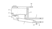
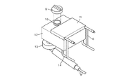
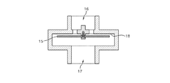
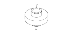
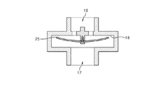
図1は、本発明の第1の実施形態に係る暖房用自然循環ボイラーの概略構成図であり、図2は、本発明に係るボイラー水槽の概略斜視図であり、図3は、図1に示す逆止弁の概略構成図であり、図4は、逆止弁の概略斜視図であり、図5及び図6は、本発明に係る電気加熱装置の概略斜視図である。図1から図6に基づき、本発明の第1の実施形態に係る暖房用自然循環式ボイラーを説明する。 FIG. 1 is a schematic configuration diagram of a heating natural circulation boiler according to a first embodiment of the present invention, FIG. 2 is a schematic perspective view of a boiler water tank according to the present invention, and FIG. FIG. 4 is a schematic perspective view of the check valve, and FIGS. 5 and 6 are schematic perspective views of the electric heating device according to the present invention. Based on FIGS. 1-6, the natural circulation boiler for heating which concerns on the 1st Embodiment of this invention is demonstrated.
本発明の第1の実施形態に係る暖房用自然循環式ボイラーは、電気加熱装置1と、逆止弁2と、水位感知器3と、水槽4と、安全弁5a、5bと、減圧管6と、吸入管7と、排出管8と、水槽排出管13と、水槽吸入部14と、第1及び第2の加熱タンク20a、20b及び発熱ヒーター23を備える。
The natural circulation boiler for heating according to the first embodiment of the present invention includes an
水槽4は、内部に水及び空気を貯溜可能な空間を有するように構成される。本実施形態の場合、水槽4は全体的に段付き正六面体または段付き直六面体の形状を呈するが、水槽の形状がこれらに限定されることはなく、水槽4は、円柱、多角柱など様々な形状を呈しても良い。 The water tank 4 is configured to have a space in which water and air can be stored. In the case of the present embodiment, the aquarium 4 generally has a stepped regular hexahedron shape or a stepped cuboidal shape, but the shape of the aquarium is not limited to these, and the aquarium 4 may have various shapes such as a cylinder and a polygonal column. It may have a different shape.
水槽4の上部には注水口10が形成され、注水口10には水槽蓋9が配設される。水槽4は段付き形状、すなわち、水槽の一方の側の高さは他方の側の高さよりも低く形成され、注水口10は水槽の高さの低い個所の上部に配設される。水槽4の他方の側は注水口10よりも上方に配置されて、水槽4に水を注水すれば、水槽4の他方の側の上部には空気が溜まる空気貯溜部11が形成され、空気貯溜部11の下方には貯水部12が形成される。
A
水槽4の一方の側の下部には孔が穿設され、この孔は水槽排出管13と連結され、水槽排出管13は逆止弁2の上連結部16と連結され、逆止弁2の下連結部17は電気加熱装置1の逆止弁側連結部19と連結される。
A hole is formed in the lower part on one side of the water tank 4, and this hole is connected to the water
電気加熱装置1はそれぞれ独立した第1の加熱タンク20aと第2の加熱タンク20bとを有し、第1の加熱タンク20aと第2の加熱タンク20bとの間には発熱ヒーター23が介装され、発熱ヒーター23は電気線21と連結される。
The
電気加熱装置1の流動区間側連結部22は排出管8と連結され、排出管8には安全弁5bが配設される。水槽4の他方の側の下部に穿設された孔は水槽吸入部14と連通され、水槽吸入部14は吸入管7と連結される。吸入管7には減圧管6が水槽4の他方の側の上部の空気貯溜部11と連通されるように形成され、減圧管6の上部には安全弁5aが配設され、水槽4の内部下面には水位感知器3が取り付けられる。
The flow section
注水口10は水槽4上部よりも低く装備され、水をいっぱいに満たした際に水槽4の上部には常に空気貯溜部11が形成され、空気貯溜部の下には貯水部が配され、水槽4の昇温時に発生する水蒸気は空気貯溜部11と連結された減圧管6、吸入管7を通りつつ減圧する。
The
上述したように、水槽4と連結された水槽排出管13は逆止弁2と連結される。水槽4に貯水された水は、逆止弁2の上連結部16と、逆止弁2および逆止弁2の下連結部17を介して電気加熱装置1に供給される。
As described above, the water
電気加熱装置1の第1の加熱タンク20aおよび第2の加熱タンク20bに給水された水は発熱ヒーター23によって加熱される。第1の加熱タンク20a及び第2の加熱タンク20bの水を加熱する際に昇温により圧力が発生する。このとき、発生した圧力は逆止弁2の逆止板15を瞬時に上昇させ、上昇させられた逆止板15は逆止弁2の胴部18の内部上面に向かって移動してくっつく。その結果、逆止板15は逆止弁2の上連結部16を閉塞して、水が水槽4に向かって逆流することを防止する。これにより、加熱された水は排出管8に向かって流れ、水が瞬時に流れるときに逆止板15は元の位置に戻る。逆止板15が元の位置に戻る瞬間、水槽4の水は逆止弁2に給水され、電気加熱装置1によって加熱された水は暖房区間に給水される。その結果、循環ポンプがなくても自然循環式により水を循環させることが可能となる。
The water supplied to the
また、電気加熱装置1は、発熱ヒーター23を真ん中に配置し、発熱ヒーター23と接するように両側に第1の加熱タンク20aおよび第2の加熱タンク20bを配設することにより、水の加熱時間を短縮させ、その結果、高い循環速度、電気節約、エネルギーの無駄使いの防止を図ることが可能となる。
Moreover, the
さらに、本発明は、加熱された水が循環して吸入管7を通ってボイラーに流入し、そのとき、水槽4の貯水部12に貯水された水の昇温により発生した蒸気は空気貯溜部11を通って減圧管6を介して吸入管7に吸収されるように構成することにより、従来の技術によるボイラーよりも1/10の減圧効果が得られ、その結果、安全使用を図ることが可能となる。
Further, according to the present invention, the heated water circulates and flows into the boiler through the
図7及び図8は、本発明の第2の実施形態に係る暖房用自然循環式ボイラーの逆止弁の概略構成図及び動作状態図である。 7 and 8 are a schematic configuration diagram and an operation state diagram of the check valve of the natural circulation boiler for heating according to the second embodiment of the present invention.
図7及び図8に基づき、第2の実施形態に係る暖房用自然循環式ボイラーの逆止弁を説明すると、逆止板25の形状が上述した第1の実施形態とは異なる形状を呈する。本実施形態の場合、逆止板25の平面形状は全体的に逆止弁の上連結部16に対応する形状を呈し、 逆止板25の直径は逆止弁の上連結部16よりも大径である。なお、逆止板25の側面形状は、平らな形状ではなく、真ん中が下方に凸状に湾曲する形状を呈する。
Based on FIG.7 and FIG.8, if the non-return valve of the natural circulation boiler for heating which concerns on 2nd Embodiment is demonstrated, the shape of the
第1の加熱タンク20a及び第2の加熱タンク20b中の水の加熱に際して昇温により発生した圧力が逆止弁2の逆止板25を瞬時に上昇させ、上昇させられた逆止板25は逆止弁2の胴部18の内部上面に向かって移動してくっつく。このとき、逆止板25は真ん中が下方に凸状に湾曲する形状を呈するため、逆止板25の周縁領域だけが逆止弁2の胴部18の内部上面にくっついて水の逆流を防止する。このように、逆止板25と逆止弁2の胴部18の内部上面との接触面積を減らすと、逆止板25が元の位置に戻る瞬間に発生する騒音がほとんどなくなり、その結果、使い勝手が向上する効果が得られる。
The pressure generated by the temperature rise during the heating of the water in the
図9は、本発明の第3の実施形態に係る暖房用自然循環式ボイラーの逆止弁の概略構成図である。 FIG. 9 is a schematic configuration diagram of a check valve of a natural circulation boiler for heating according to a third embodiment of the present invention.
図9に示す逆止弁の場合、逆止板15は平らな形状に形成するが、逆止弁の胴部18の内部上面には多数の溝28が凹設されている。逆止板15と逆止弁の胴部18の内部上面とが接触する領域に多数の溝28を凹設すれば、逆止板15を平らな形状に形成しても、逆止板15と逆止弁2の胴部18の内部上面との間の接触面積を減らすことが可能になる。
In the case of the check valve shown in FIG. 9, the
その結果、逆止板15が逆止弁2の胴部18の内部上面と接触していて元の位置に戻る瞬間に発生する騒音を極力抑えることができる。
As a result, the noise generated at the moment when the
図10は、本発明の第4の実施形態に係る暖房用自然循環式ボイラーの逆止弁の概略構成図である。 FIG. 10 is a schematic configuration diagram of a check valve of a natural circulation boiler for heating according to the fourth embodiment of the present invention.
図10に基づき、第4の実施形態に係る暖房用自然循環式ボイラーの逆止弁を説明すると、逆止弁2の逆止板15にはバネ部材29が配設される。第1の加熱タンク20a及び第2の加熱タンク20b中の水の加熱に際して昇温により発生した圧力が逆止弁2の逆止板15を瞬時に上昇させる。上昇させられた逆止板15は逆止弁2の胴部18の内部上面に向かってくっつき、しかる後に元の位置に戻るときにバネ部材29の弾性力によって一層容易に引き離れて、元の位置に戻る瞬間に発生する騒音を極力抑えることができ、逆止板15の誤動作に起因して水の循環が止まることを未然に防止することができる。
Based on FIG. 10, the check valve of the natural circulation boiler for heating according to the fourth embodiment will be described. A
図11及び図12は、本発明の第5の実施形態に係る暖房用自然循環式ボイラーの概略構成図及び動作状態図である。 11 and 12 are a schematic configuration diagram and an operation state diagram of a heating natural circulation boiler according to the fifth embodiment of the present invention.
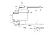
本発明の第5の実施形態に係る暖房用自然循環式ボイラーは、電気加熱装置1と、逆止弁2と、水位感知器3と、水槽4と、安全弁5bと、吸入管7と、排出管8と、可変エアーバッグ31と、第1の可変エアーバッグ連結部32と、第2の可変エアーバッグ連結部33と、空気排出弁40と、空気排出弁制御器50及び感知部61、62を備える。
A natural circulation boiler for heating according to a fifth embodiment of the present invention includes an
水槽4の上部には注水口が形成され、水槽4は段付き形状、すなわち、水槽の一方の側の高さは他方の側の高さよりも低く形成され、注水口は水槽の高さの低い個所の上部に配設される。水槽4の他方の側は注水口よりも上方に配置されて、水槽4に水を注水すれば、水槽4の他方の側の上部には空気が溜まる空気貯溜部が形成される。 A water inlet is formed in the upper part of the water tank 4, and the water tank 4 has a stepped shape, that is, the height of one side of the water tank is lower than the height of the other side, and the water inlet is lower in height of the water tank. Arranged at the top of the location. The other side of the water tank 4 is arranged above the water inlet, and when water is poured into the water tank 4, an air reservoir for storing air is formed at the upper part of the other side of the water tank 4.
水槽4の他方の側の上部には可変エアーバッグ31が配設される。本実施形態の場合、段付き水槽4の他方の側の上部に別の可変エアーバッグ31を配設しているが、水槽4の空気貯溜部に相当する個所の体積が可変するように形成してもよい。可変エアーバッグ31の一方の側には第1の可変エアーバッグ連結部32が形成されて、可変エアーバッグ31と水槽4の空気貯溜部とを連通させる。なお、可変エアーバッグ31の一方の側や上部に第2の可変エアーバッグ連結部33が形成されて、可変エアーバッグ31と空気排出弁40とを連結させる。
A variable air bag 31 is disposed on the other side of the water tank 4. In the case of this embodiment, another variable air bag 31 is disposed on the other side of the stepped water tank 4, but the volume of the portion corresponding to the air reservoir of the water tank 4 is formed to be variable. May be. A first variable
感知部61、62は可変エアーバッグ31に溜まった空気の量を感知し、その感知結果を空気排出弁制御器50に送る。空気排出弁制御器50は、感知部61、62における感知結果に基づき、空気排出弁40の動作を制御する。本実施形態において、感知部61、62としては接触式センサーを用いているが、本発明はこれに限定されるものではなく、様々な方式により可変エアーバッグ31の空気量を感知することができる。
The
図11に示すように、感知部の第1の端子61は可変エアーバッグ31の上端に配設され、第2の端子62は第1の端子から所定距離だけ離れて配置される。水槽4において生成される蒸気の量が少量であるときには可変エアーバッグ31は低い体積の状態を維持するが、蒸気の量が増大し続けると、可変エアーバッグ31の体積も次第に増大し、これに伴い、図12に示すように、第1の端子と第2の端子とが接触して接触信号が発生する。この接触信号は空気排出弁制御器50に受け渡され、空気排出弁制御器50は空気排出弁40を開放するように制御する。その結果、可変エアーバッグ31に溜まった蒸気は第2の可変エアーバッグ連結部33を経て空気排出弁40を介して外部に排出されてボイラー内の圧力は減少する。所定の時間が経過後、空気排出弁制御器50は空気排出弁40を閉止することを指示する。
As shown in FIG. 11, the
本実施形態のように、可変エアーバッグを配設することで、圧力が発生すれば可変エアーバッグを膨張させて圧力を制御して安全に使用することができ、しかも、騒音の発生を抑えることができる。また、可変エアーバッグがそれ以上膨張できない場合には、蒸気を外部に排出して少量の水分のみ減らして圧力を調節することにより、ボイラーの水を補充することなく長期に亘って使用することができる。 As in this embodiment, by arranging a variable air bag, if a pressure is generated, the variable air bag can be inflated to control the pressure and be used safely, and to suppress the generation of noise. Can do. If the variable airbag cannot be expanded any more, it can be used for a long time without refilling the boiler water by adjusting the pressure by discharging steam to the outside and reducing only a small amount of water. it can.
図13は、本発明の第6の実施形態に係る暖房用自然循環式ボイラーの概略構成図である。図13に示す第6の実施形態は、第5の実施形態と比べて、減圧管を付設している点で相違点があり、残りの構成は同様であるため、以下、相違点を中心に詳述する。 FIG. 13: is a schematic block diagram of the natural circulation boiler for heating which concerns on the 6th Embodiment of this invention. The sixth embodiment shown in FIG. 13 is different from the fifth embodiment in that a pressure reducing tube is attached, and the rest of the configuration is the same. Detailed description.
本発明の第6の実施形態に係る暖房用自然循環式ボイラーは、電気加熱装置1と、逆止弁2と、水位感知器3と、水槽4と、安全弁5bと、減圧管6と、吸入管7と、排出管8と、可変エアーバッグ31と、第1の可変エアーバッグ連結部32と、第2の可変エアーバッグ連結部33と、空気排出弁40と、空気排出弁制御器50及び感知部61、62を備える。
A natural circulation boiler for heating according to a sixth embodiment of the present invention includes an
水槽4の上部には注水口が形成され、水槽4は段付き形状、すなわち、水槽の一方の側の高さは他方の側の高さよりも低く形成され、注水口は水槽の高さの低い個所の上部に配設される。水槽4の他方の側は注水口よりも上部に配置されて、水槽4に水を注水すれば、水槽4の他方の側の上部には空気が溜まる空気貯溜部が形成される。吸入管7には減圧管6が水槽4の他方の側の上部の空気貯溜部と連通されるように形成される。水槽4の他方の側の上部には可変エアーバッグ31が配設される。可変エアーバッグ31の一方の側には第1の可変エアーバッグ連結部32が形成されて、可変エアーバッグ31と水槽4の空気貯溜部とを連通させる。なお、可変エアーバッグ31の一方の側や上部に第2の可変エアーバッグ連結部33が形成されて、可変エアーバッグ31と空気排出弁40とを連結させる。
A water inlet is formed in the upper part of the water tank 4, and the water tank 4 has a stepped shape, that is, the height of one side of the water tank is lower than the height of the other side, and the water inlet is lower in height of the water tank. Arranged at the top of the location. The other side of the water tank 4 is disposed above the water inlet, and when water is poured into the water tank 4, an air reservoir for storing air is formed at the upper part of the other side of the water tank 4. The
水槽4に貯水された水の昇温により発生した蒸気の一部は可変エアーバッグ31を膨張させ、一部は空気貯溜部を通って減圧管6を介して吸入管7に吸収されるように構成することにより、一層少量の蒸気を外部に排出して少量の水分のみ減らして圧力を調節し、その結果、ボイラーの水を補充することなく長期に亘って使用することができる。
A part of the steam generated by the temperature rise of the water stored in the water tank 4 inflates the variable airbag 31, and a part of the steam passes through the air reservoir and is absorbed by the
図14は、本発明の第7の実施形態に係る暖房用自然循環式ボイラーの概略構成図である。 FIG. 14 is a schematic configuration diagram of a heating natural circulation boiler according to a seventh embodiment of the present invention.
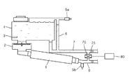
本発明の第7の実施形態に係る暖房用自然循環式ボイラーは、電気加熱装置1と、逆止弁2と、水位感知器3と、水槽4と、安全弁5a、5bと、減圧管6と、吸入管7と、排出管8と、調圧弁70及び感圧部80を備える。
The natural circulation boiler for heating according to the seventh embodiment of the present invention includes an
電気加熱装置1の一方の端は排出管8と連結され、排出管8には安全弁5bが配設される。水槽4の他方の側の下部に穿設された孔は水槽吸入部(図示せず)を介して吸入管7と連結される。吸入管7には減圧管6が水槽4の他方の側の上部の空気貯溜部11と連通されるように形成され、減圧管6の上部には安全弁5aが配設され、水槽4の内部下面には水位感知器3が取り付けられる。
One end of the
さらに、吸入管7と排出管8との間には連結管75が介装されて吸入管7と排出管8とを連通させ、連結管75には調圧弁70が配設される。感圧部80は連結管75に働く圧力を感知し、その感知結果に基づき、調圧弁70の動作及び電気加熱装置1の動作を制御する機能をする。
Further, a
外部の圧力によって管に目詰まりが生じたり直径が縮まったりすると、ボイラーから排出管8を通って暖房区間に至るまでの水の循環がスムーズに行われず、その結果、電気加熱装置1における圧力が増大してしまう。感圧部80は圧力を感知し、所定の圧力以上に圧力が増大した場合に調圧弁70を開放して、排出管を通って暖房区間に流れる水を吸収管に導くことにより圧力を減らすか、あるいは、これと併せて、電気加熱装置1の電源を遮断することにより気加熱装置の圧力が増大することを防いでボイラーを一層安全に使用することができる。
When the tube is clogged or the diameter is reduced by the external pressure, the water is not smoothly circulated from the boiler through the
以上述べた実施形態は、本発明に係る暖房用自然循環式ボイラーの単なる例示的な実施形態に過ぎず、本発明は上述した実施形態に限定されるものではなく、特許請求の範囲において請求するように、本発明の要旨を逸脱することなく、当該発明が属する分野において通常の知識を持った者であれば、誰でも様々な変更実施が可能な範囲まで本発明の技術的精神があるといえる。 The embodiment described above is merely an exemplary embodiment of the natural circulation boiler for heating according to the present invention, and the present invention is not limited to the above-described embodiment, and is claimed in the scope of the claims. Thus, any person who has ordinary knowledge in the field to which the present invention belongs without departing from the gist of the present invention has the technical spirit of the present invention to the extent that various modifications can be made. I can say that.
1 電気加熱装置
2 逆止弁
3 水位感知器
4 水槽
5a、5b 安全弁
6 減圧管
7 吸入管
8 排出管
9 水槽蓋
10 注水口
11 空気貯溜部
12 貯水部
13 水槽排出管
14 水槽吸入部
15 逆止板
16 逆止弁の上連結部
17 逆止弁の下連結部
18 逆止弁胴部
19 逆止弁側連結部
20a 第1の加熱タンク
20b 第2の加熱タンク
21 電気線
22 流動区間側連結部、
23 発熱ヒーター
28 溝
29 バネ部材
31 可変エアーバッグ
40 空気排出弁
50 空気排出弁制御器
70 調圧弁
80 感圧部
DESCRIPTION OF
23
Claims (13)
前記水槽の下部に配設され、胴部と、前記胴部の上部に形成された上連結部と、前記胴部の下部に形成された下連結部及び前記上連結部の流路を開閉する逆止板を有する逆止弁と、
一方の端は前記水槽の一方の側の下部に穿設された孔と連結され、他方の端は前記逆止弁の上連結部と連結される水槽排出管と、
一方の端は前記逆止弁の下連結部に連結されて、前記水槽から給水される水を加熱する電気加熱装置と、
前記電気加熱装置において加熱された水を暖房区間に搬送するために、前記電気加熱装置の他方の端に連結された排出管と、
前記水槽の他方の側の下部に穿設された孔と連通されるように形成された水槽吸入部と、
一方の端が前記水槽吸入部に連結される吸入管と、
一方の端は前記吸入管と連通され、他方の端は前記水槽の他方の側の上部の空気貯溜部と連通されるように形成された減圧管と
を備えることを特徴とする暖房用自然循環式ボイラー。 The height of one side is formed lower than the height of the other side so as to have a water storage part for storing water and an air storage part for storing air, and a water inlet is formed in the upper part of the one side Aquarium
The body is disposed in the lower part of the water tank, and opens and closes the body part, the upper connection part formed in the upper part of the body part, the lower connection part formed in the lower part of the body part, and the flow path of the upper connection part. A check valve having a check plate;
One end is connected to a hole drilled in a lower portion on one side of the water tank, and the other end is a water tank discharge pipe connected to the upper connection portion of the check valve;
One end is connected to a lower connection portion of the check valve, and an electric heating device that heats water supplied from the water tank;
A discharge pipe connected to the other end of the electric heating device to convey water heated in the electric heating device to a heating section;
A water tank suction part formed so as to communicate with a hole formed in a lower part on the other side of the water tank;
A suction pipe having one end connected to the water tank suction part;
A natural circulation for heating, comprising: one end communicated with the suction pipe, and the other end provided with a decompression pipe formed to communicate with an upper air reservoir on the other side of the water tank. Formula boiler.
前記連結管に配設された調圧弁と、
前記連結管に働く圧力を感知し、感知された結果に基づき、前記調圧弁の動作及び前記電気加熱装置の動作を制御する感圧部と
をさらに備えることを特徴とする請求項1に記載の暖房用自然循環式ボイラー。 A connecting pipe communicating the suction pipe and the discharge pipe;
A pressure regulating valve disposed in the connecting pipe;
The pressure sensing unit according to claim 1, further comprising: a pressure sensing unit that senses a pressure acting on the connecting pipe and controls an operation of the pressure regulating valve and an operation of the electric heating device based on the sensed result. Natural circulation boiler for heating.
前記水槽の他方の側の上部に配設された可変エアーバッグと、
前記可変エアーバッグの一方の側に形成されて前記水槽の空気貯溜部と連結される第1の可変エアーバッグ連結部と、
前記可変エアーバッグの一方の側や上部に形成された第2の可変エアーバッグ連結部を介して前記可変エアーバッグと連結された空気排出弁と、
前記水槽の下部に配設され、胴部と、前記胴部の上部に形成された上連結部と、前記胴部の下部に形成された下連結部及び前記上連結部の流路を開閉する逆止板を有する逆止弁と、
一方の端は前記水槽の一方の側の下部に穿設された孔と連結され、他方の端は前記逆止弁の上連結部と連結される水槽排出管と、
一方の端は前記逆止弁の下連結部に連結されて、前記水槽から給水される水を加熱する電気加熱装置と、
前記電気加熱装置において加熱された水を暖房区間に搬送するために、前記電気加熱装置の他方の端に連結された排出管と、
前記水槽の他方の側下部に穿設された孔と連通されるように形成された水槽吸入部と、
一方の端が前記水槽吸入部に連結される吸入管と
を備えることを特徴とする暖房用自然循環式ボイラー。 The height of one side is formed lower than the height of the other side so as to have a water storage part for storing water and an air storage part for storing air, and a water inlet is formed in the upper part of the one side The aquarium
A variable airbag disposed on the other side of the water tank;
A first variable air bag connecting portion formed on one side of the variable air bag and connected to the air reservoir of the water tank;
An air discharge valve connected to the variable airbag via a second variable airbag connecting portion formed on one side or upper part of the variable airbag;
The body is disposed in the lower part of the water tank, and opens and closes the body part, the upper connection part formed in the upper part of the body part, the lower connection part formed in the lower part of the body part, and the flow path of the upper connection part. A check valve having a check plate;
One end is connected to a hole drilled in a lower portion on one side of the water tank, and the other end is a water tank discharge pipe connected to the upper connection portion of the check valve;
One end is connected to a lower connection portion of the check valve, and an electric heating device that heats water supplied from the water tank;
A discharge pipe connected to the other end of the electric heating device to convey water heated in the electric heating device to a heating section;
A water tank suction part formed so as to communicate with a hole formed in the lower part of the other side of the water tank;
A natural circulation boiler for heating, comprising: a suction pipe connected at one end to the water tank suction part.
前記感知部の感知結果に基づき、前記空気排出弁の動作を制御する空気排出弁制御器と
をさらに備えることを特徴とする請求項11に記載の暖房用自然循環式ボイラー。 A sensing unit for sensing the amount of air stored in the variable airbag;
The heating natural circulation boiler according to claim 11, further comprising: an air discharge valve controller that controls an operation of the air discharge valve based on a detection result of the detection unit.
Applications Claiming Priority (3)
| Application Number | Priority Date | Filing Date | Title |
|---|---|---|---|
| CN200810157986.8 | 2008-10-22 | ||
| CN2008101579868A CN101392952B (en) | 2008-10-22 | 2008-10-22 | Self-circulation boiler for heating |
| PCT/KR2009/006102 WO2010047535A2 (en) | 2008-10-22 | 2009-10-21 | Natural circulation mode boiler for heating |
Publications (1)
| Publication Number | Publication Date |
|---|---|
| JP2012509451A true JP2012509451A (en) | 2012-04-19 |
Family
ID=40493370
Family Applications (1)
| Application Number | Title | Priority Date | Filing Date |
|---|---|---|---|
| JP2011533106A Ceased JP2012509451A (en) | 2008-10-22 | 2009-10-21 | Natural circulation boiler for heating |
Country Status (6)
| Country | Link |
|---|---|
| US (1) | US20120017850A1 (en) |
| EP (1) | EP2381185A2 (en) |
| JP (1) | JP2012509451A (en) |
| KR (1) | KR101096168B1 (en) |
| CN (1) | CN101392952B (en) |
| WO (1) | WO2010047535A2 (en) |
Cited By (3)
| Publication number | Priority date | Publication date | Assignee | Title |
|---|---|---|---|---|
| JP2012511693A (en) * | 2009-02-17 | 2012-05-24 | ユーロハウジング コーポレーション | Mobile boiler for heating mat |
| JP6018328B1 (en) * | 2015-08-24 | 2016-11-02 | 三元オンスパー株式会社 | Hot water boiler for hot water mat |
| JP2017505891A (en) * | 2013-12-23 | 2017-02-23 | ヤン ジョン キム | Fluid circulation heating system |
Families Citing this family (8)
| Publication number | Priority date | Publication date | Assignee | Title |
|---|---|---|---|---|
| KR101230543B1 (en) * | 2010-10-25 | 2013-02-06 | 정문식 | Counter Current Protection Apparatus and Heating Boiler with Power |
| WO2012057481A2 (en) * | 2010-10-25 | 2012-05-03 | Park Hoo Bong | Unpowered small-volume heating boiler, and backflow-preventing apparatus for the unpowered small-volume heating boiler |
| KR101043754B1 (en) * | 2010-11-16 | 2011-06-22 | 주식회사 동양이지텍 | A water level controller for hot-water boiler mat |
| EP2894416A4 (en) * | 2012-07-20 | 2016-10-12 | Yoon Min Shin | Hot-water boiler, heating pipes and installation structure therefor |
| KR101243865B1 (en) * | 2012-08-20 | 2013-03-20 | 남궁금자 | Apparatus for supplying warm water |
| CN103017255B (en) * | 2012-12-07 | 2015-12-02 | 宁波阿帕奇机械有限公司 | The combustion module of kerosene heater |
| KR101418947B1 (en) * | 2013-10-02 | 2014-07-11 | 삼원온스파주식회사 | Boiler for hot-water heating mat |
| KR20190009945A (en) * | 2017-07-20 | 2019-01-30 | 장백지 | The hot-water naturally circulation heating apparatus |
Citations (4)
| Publication number | Priority date | Publication date | Assignee | Title |
|---|---|---|---|---|
| JPS4110598Y1 (en) * | 1964-02-19 | 1966-05-19 | ||
| JPS60186626A (en) * | 1984-03-06 | 1985-09-24 | Tokyo Gas Co Ltd | Method of carrying heat in house |
| JPH03129246A (en) * | 1989-10-14 | 1991-06-03 | Toyotomi Kogyo Co Ltd | Hot water room heater |
| KR20020079246A (en) * | 2001-04-14 | 2002-10-19 | 워터로테크(주) | Multipurpose hot water circulation pumping apparatus |
Family Cites Families (11)
| Publication number | Priority date | Publication date | Assignee | Title |
|---|---|---|---|---|
| JPS6146845A (en) * | 1984-08-11 | 1986-03-07 | Matsushita Electric Ind Co Ltd | Hot water boiler |
| KR890002956Y1 (en) * | 1986-09-11 | 1989-05-10 | 장봉석 | Dual circulation device of hot-water heater combined pump and water tank |
| CN1055418A (en) * | 1991-04-06 | 1991-10-16 | 李官洙 | Pumpless forced circulation boiler for hot-water heating |
| KR0132627Y1 (en) * | 1996-03-13 | 1998-12-15 | 박헌웅 | Electric boiler with water level adjusting function |
| US5724478A (en) * | 1996-05-14 | 1998-03-03 | Truheat Corporation | Liquid heater assembly |
| DE19854910B4 (en) * | 1998-11-27 | 2004-09-02 | Max Weishaupt Gmbh | boiler |
| KR200184695Y1 (en) * | 1999-12-31 | 2000-06-01 | 원광재 | Multipurpose hot water circulating apparatus |
| CN100373096C (en) * | 2003-06-11 | 2008-03-05 | 金斗年 | Method and device of inserting a coated electric heating wire into a hot water tube and a sealing apparatus thereof |
| KR100725250B1 (en) | 2007-03-16 | 2007-06-04 | 박연홍 | Boiling and recirculating device for hot-water heating type mat |
| CN101149183B (en) * | 2007-10-23 | 2011-07-06 | 朱福霖 | High temperature automatic forced-circulation boiler |
| CN201322433Y (en) * | 2008-10-22 | 2009-10-07 | 威海柯碧思木业有限公司 | Self-circulating boiler for heating |
-
2008
- 2008-10-22 CN CN2008101579868A patent/CN101392952B/en not_active Expired - Fee Related
-
2009
- 2009-10-21 KR KR1020090100448A patent/KR101096168B1/en not_active IP Right Cessation
- 2009-10-21 WO PCT/KR2009/006102 patent/WO2010047535A2/en active Application Filing
- 2009-10-21 JP JP2011533106A patent/JP2012509451A/en not_active Ceased
- 2009-10-21 EP EP09822211A patent/EP2381185A2/en not_active Withdrawn
- 2009-10-21 US US13/129,083 patent/US20120017850A1/en not_active Abandoned
Patent Citations (4)
| Publication number | Priority date | Publication date | Assignee | Title |
|---|---|---|---|---|
| JPS4110598Y1 (en) * | 1964-02-19 | 1966-05-19 | ||
| JPS60186626A (en) * | 1984-03-06 | 1985-09-24 | Tokyo Gas Co Ltd | Method of carrying heat in house |
| JPH03129246A (en) * | 1989-10-14 | 1991-06-03 | Toyotomi Kogyo Co Ltd | Hot water room heater |
| KR20020079246A (en) * | 2001-04-14 | 2002-10-19 | 워터로테크(주) | Multipurpose hot water circulation pumping apparatus |
Cited By (3)
| Publication number | Priority date | Publication date | Assignee | Title |
|---|---|---|---|---|
| JP2012511693A (en) * | 2009-02-17 | 2012-05-24 | ユーロハウジング コーポレーション | Mobile boiler for heating mat |
| JP2017505891A (en) * | 2013-12-23 | 2017-02-23 | ヤン ジョン キム | Fluid circulation heating system |
| JP6018328B1 (en) * | 2015-08-24 | 2016-11-02 | 三元オンスパー株式会社 | Hot water boiler for hot water mat |
Also Published As
| Publication number | Publication date |
|---|---|
| EP2381185A2 (en) | 2011-10-26 |
| CN101392952B (en) | 2013-03-20 |
| KR101096168B1 (en) | 2011-12-22 |
| WO2010047535A3 (en) | 2010-08-05 |
| US20120017850A1 (en) | 2012-01-26 |
| KR20100044719A (en) | 2010-04-30 |
| WO2010047535A2 (en) | 2010-04-29 |
| CN101392952A (en) | 2009-03-25 |
Similar Documents
| Publication | Publication Date | Title |
|---|---|---|
| JP2012509451A (en) | Natural circulation boiler for heating | |
| KR100861167B1 (en) | hot water circulation system | |
| KR101110551B1 (en) | A Hot-water pumping appratus without power | |
| KR20070000493U (en) | hot water circulation system of non-driving pump | |
| US20110259560A1 (en) | Hot water storage type hot water supply device | |
| KR101230543B1 (en) | Counter Current Protection Apparatus and Heating Boiler with Power | |
| JP5257059B2 (en) | Hot water storage water heater | |
| TWI526658B (en) | Storage water heater with instant hot water supply and control method thereof | |
| KR101432194B1 (en) | Heating mat using hot-water boiler | |
| KR100957056B1 (en) | Electric boiler | |
| KR200421793Y1 (en) | Boiler for mat | |
| KR200434072Y1 (en) | Boiler for mat | |
| KR101197371B1 (en) | Portable Device to Supply Warm Water | |
| KR200442500Y1 (en) | Electric steam boiler | |
| KR20120113044A (en) | Check valve for boiler and a boiler comprising the same | |
| KR20080008307A (en) | Heater make use of hot-water | |
| CN205119439U (en) | Foot bath tub | |
| KR101432195B1 (en) | Hot water mat using hot water boiler | |
| KR101042723B1 (en) | A hot water circulation device using the vapor pressure | |
| KR20100031335A (en) | Heat medium circulating system using ceramic heater | |
| JP5018003B2 (en) | Hot water storage water heater | |
| KR100845298B1 (en) | A heater for a compulsory circular hot water mat used of heat energy | |
| KR101151771B1 (en) | A hot water circulation device using the vapor pressure | |
| KR20090098363A (en) | Heater structure for warm water supply device | |
| JP3140872U (en) | Water heater |
Legal Events
| Date | Code | Title | Description |
|---|---|---|---|
| A01 | Written decision to grant a patent or to grant a registration (utility model) |
Free format text: JAPANESE INTERMEDIATE CODE: A01 Effective date: 20121211 |
|
| A045 | Written measure of dismissal of application [lapsed due to lack of payment] |
Free format text: JAPANESE INTERMEDIATE CODE: A045 Effective date: 20130423 |