JP2012509196A - Double-sided ball end mill cutting insert and insert tool - Google Patents
Double-sided ball end mill cutting insert and insert tool Download PDFInfo
- Publication number
- JP2012509196A JP2012509196A JP2011536617A JP2011536617A JP2012509196A JP 2012509196 A JP2012509196 A JP 2012509196A JP 2011536617 A JP2011536617 A JP 2011536617A JP 2011536617 A JP2011536617 A JP 2011536617A JP 2012509196 A JP2012509196 A JP 2012509196A
- Authority
- JP
- Japan
- Prior art keywords
- curved side
- insert
- cutting insert
- receiving pocket
- support surface
- Prior art date
- Legal status (The legal status is an assumption and is not a legal conclusion. Google has not performed a legal analysis and makes no representation as to the accuracy of the status listed.)
- Pending
Links
- 239000002826 coolant Substances 0.000 claims description 3
- 238000003754 machining Methods 0.000 description 4
- 238000003801 milling Methods 0.000 description 4
- 229910003460 diamond Inorganic materials 0.000 description 1
- 239000010432 diamond Substances 0.000 description 1
- 239000002184 metal Substances 0.000 description 1
- 238000005555 metalworking Methods 0.000 description 1
- 230000002265 prevention Effects 0.000 description 1
- 238000010008 shearing Methods 0.000 description 1
Images


Classifications
-
- B—PERFORMING OPERATIONS; TRANSPORTING
- B23—MACHINE TOOLS; METAL-WORKING NOT OTHERWISE PROVIDED FOR
- B23C—MILLING
- B23C5/00—Milling-cutters
- B23C5/02—Milling-cutters characterised by the shape of the cutter
- B23C5/10—Shank-type cutters, i.e. with an integral shaft
- B23C5/1009—Ball nose end mills
- B23C5/1027—Ball nose end mills with one or more removable cutting inserts
- B23C5/1045—Ball nose end mills with one or more removable cutting inserts having a cutting insert, the cutting edge of which subtends substantially 90 degrees
-
- B—PERFORMING OPERATIONS; TRANSPORTING
- B23—MACHINE TOOLS; METAL-WORKING NOT OTHERWISE PROVIDED FOR
- B23C—MILLING
- B23C5/00—Milling-cutters
- B23C5/16—Milling-cutters characterised by physical features other than shape
- B23C5/20—Milling-cutters characterised by physical features other than shape with removable cutter bits or teeth or cutting inserts
- B23C5/22—Securing arrangements for bits or teeth or cutting inserts
- B23C5/2204—Securing arrangements for bits or teeth or cutting inserts with cutting inserts clamped against the walls of the recess in the cutter body by a clamping member acting upon the wall of a hole in the insert
- B23C5/2208—Securing arrangements for bits or teeth or cutting inserts with cutting inserts clamped against the walls of the recess in the cutter body by a clamping member acting upon the wall of a hole in the insert for plate-like cutting inserts
- B23C5/2213—Securing arrangements for bits or teeth or cutting inserts with cutting inserts clamped against the walls of the recess in the cutter body by a clamping member acting upon the wall of a hole in the insert for plate-like cutting inserts having a special shape
-
- B—PERFORMING OPERATIONS; TRANSPORTING
- B23—MACHINE TOOLS; METAL-WORKING NOT OTHERWISE PROVIDED FOR
- B23C—MILLING
- B23C2200/00—Details of milling cutting inserts
- B23C2200/12—Side or flank surfaces
- B23C2200/128—Side or flank surfaces with one or more grooves
-
- B—PERFORMING OPERATIONS; TRANSPORTING
- B23—MACHINE TOOLS; METAL-WORKING NOT OTHERWISE PROVIDED FOR
- B23C—MILLING
- B23C2200/00—Details of milling cutting inserts
- B23C2200/20—Top or side views of the cutting edge
- B23C2200/203—Curved cutting edges
-
- B—PERFORMING OPERATIONS; TRANSPORTING
- B23—MACHINE TOOLS; METAL-WORKING NOT OTHERWISE PROVIDED FOR
- B23C—MILLING
- B23C2210/00—Details of milling cutters
- B23C2210/16—Fixation of inserts or cutting bits in the tool
- B23C2210/168—Seats for cutting inserts, supports for replacable cutting bits
-
- B—PERFORMING OPERATIONS; TRANSPORTING
- B23—MACHINE TOOLS; METAL-WORKING NOT OTHERWISE PROVIDED FOR
- B23C—MILLING
- B23C2250/00—Compensating adverse effects during milling
- B23C2250/12—Cooling and lubrication
-
- Y—GENERAL TAGGING OF NEW TECHNOLOGICAL DEVELOPMENTS; GENERAL TAGGING OF CROSS-SECTIONAL TECHNOLOGIES SPANNING OVER SEVERAL SECTIONS OF THE IPC; TECHNICAL SUBJECTS COVERED BY FORMER USPC CROSS-REFERENCE ART COLLECTIONS [XRACs] AND DIGESTS
- Y10—TECHNICAL SUBJECTS COVERED BY FORMER USPC
- Y10T—TECHNICAL SUBJECTS COVERED BY FORMER US CLASSIFICATION
- Y10T407/00—Cutters, for shaping
- Y10T407/19—Rotary cutting tool
- Y10T407/1906—Rotary cutting tool including holder [i.e., head] having seat for inserted tool
- Y10T407/1908—Face or end mill
- Y10T407/1924—Specified tool shape
-
- Y—GENERAL TAGGING OF NEW TECHNOLOGICAL DEVELOPMENTS; GENERAL TAGGING OF CROSS-SECTIONAL TECHNOLOGIES SPANNING OVER SEVERAL SECTIONS OF THE IPC; TECHNICAL SUBJECTS COVERED BY FORMER USPC CROSS-REFERENCE ART COLLECTIONS [XRACs] AND DIGESTS
- Y10—TECHNICAL SUBJECTS COVERED BY FORMER USPC
- Y10T—TECHNICAL SUBJECTS COVERED BY FORMER US CLASSIFICATION
- Y10T407/00—Cutters, for shaping
- Y10T407/23—Cutters, for shaping including tool having plural alternatively usable cutting edges
- Y10T407/235—Cutters, for shaping including tool having plural alternatively usable cutting edges with integral chip breaker, guide or deflector
Abstract
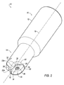
両面ボールエンドミル(10)は、略半球状前方端部(14)及び後方端部(16)を有する本体(12)を有する。前方端部(14)は、インサート受入ポケット(20a,20b)及び切屑ポケット(22a,22b)を有する。切削インサート(40)を各インサート受入ポケット(20a,20b)内に取り付けることができる。切削インサート(40)は、第1の実質的平面(42)、第2の実質的平面(44)、第1曲線側面(46)、第2曲線側面(48)、第1の実質的平面(42)と第1曲線側面(46)および第2曲線側面(48)との間の交差部分に形成された切削エッジの第1対(54,56)、及び第2の実質的平面(44)と第1曲線側面(46)および第2曲線側面(48)との間の交差部分に形成された切削エッジの第2対(58,60)を有する。第1平面(42)及び第2平面(48)は実質的に互いに平行であり、切削インサート(40)は3つの軸すべてを中心に鏡面対称である。 The double-sided ball end mill (10) has a main body (12) having a substantially hemispherical front end (14) and a rear end (16). The front end (14) has an insert receiving pocket (20a, 20b) and a chip pocket (22a, 22b). A cutting insert (40) can be mounted in each insert receiving pocket (20a, 20b). The cutting insert (40) includes a first substantially planar surface (42), a second substantially planar surface (44), a first curved side surface (46), a second curved side surface (48), a first substantially planar surface ( 42) and a first pair of cutting edges (54,56) formed at the intersection between the first curved side surface (46) and the second curved side surface (48), and a second substantially planar surface (44). And a second pair (58, 60) of cutting edges formed at the intersection between the first curved side (46) and the second curved side (48). The first plane (42) and the second plane (48) are substantially parallel to each other, and the cutting insert (40) is mirror symmetric about all three axes.
Description
本発明は、概して、ボールエンドミル用の切削インサートに関し、特に、切削インサートがボールエンドミルに取り付けられている時にエラー防止手段(ポカヨケ)(error proofing)を必要とすることなく任意の方向に切削することができる、4つの切削エッジを有するボールエンドミル用の両面切削インサートに関する。 The present invention relates generally to cutting inserts for ball end mills, and more particularly to cutting in any direction without the need for error proofing when the cutting insert is attached to the ball end mill. It relates to a double-sided cutting insert for a ball end mill having four cutting edges.
ボールノーズエンドミルは、金型空洞の倣いフライス削り用の完全に丸い切削エッジの固有の強度およびフライス削りの利点が最もよく実証される金型作製を含む、多くの金属加工の応用で使用されている。エンドミルは、ボール形状であることにより、任意の角度又は方向から金型空洞を積極的に切削する(attack)ことができる。切削エッジは、ボールミルの端部を通して生成される時、回転によりらせん状になる。これにより、切削される金属のせん断が効率的に促進される。 Ball nose end mills are used in many metalworking applications, including mold making where the inherent strength of a fully round cutting edge and the benefits of milling are best demonstrated for profile milling of mold cavities. Yes. Since the end mill has a ball shape, the mold cavity can be aggressively cut from any angle or direction. When the cutting edge is generated through the end of the ball mill, it becomes helical upon rotation. Thereby, the shearing of the metal to be cut is efficiently promoted.
従来のボールノーズエンドミルは、略半球状前方端部を有する略円筒状エンドミル本体を有している。前方端部には、2つのインサート受入座部または凹部が、互いに直径方向に反対に形成されている。2つの座部には、2つの割出可能な切削インサートが取り付けられ、そこに締付ねじによって固定されている。 A conventional ball nose end mill has a substantially cylindrical end mill body having a substantially hemispherical front end. At the front end, two insert receiving seats or recesses are formed diametrically opposite each other. Two indexable cutting inserts are attached to the two seats, and are fixed thereto by fastening screws.
ボールノースエンドミルは、ドリルに非常に類似するプランジタイプの切削か、または従来のフライスヘッドのようなフェイスタイプのフライス削りか、またはさらには、プランジタイプ切削およびフェイスタイプ切削の両方の動きを結合するランプタイプの機械作業を行うことができる非常に汎用性の高い機械工具であることが証明されている。しかしながら、従来のボールエンドミルで使用される切削インサートは、切削インサートの一方の側面に最大でも2つの切削エッジしかなく、他方の側面は厳密に座面として使用されている。その結果、切削インサートの半分は使用されておらず、それにより、こうした従来のエンドミルの作業コスト全体が増大する。 The ball north end mill is a plunge type cutting very similar to a drill, or a face type milling like a conventional milling head, or even combines the movements of both plunge type cutting and face type cutting It has proven to be a very versatile machine tool that can perform ramp-type machine work. However, cutting inserts used in conventional ball end mills have at most two cutting edges on one side of the cutting insert, and the other side is strictly used as a seating surface. As a result, half of the cutting inserts are not used, thereby increasing the overall operating cost of these conventional end mills.
端的に、本発明の別の態様によれば、ボールエンドミルのインサート受入ポケット内に取り付け可能な切削インサートが提供される。切削インサートは、第1の実質的平面と、第2の実質的平面と、第1曲線側面と、第2曲線側面と、第1の実質的平面と第1曲線側面および第2曲線側面との間の交差部分に形成された切削エッジの第1対と、第2の実質的平面と第1曲線側面および第2曲線側面との間の交差部分に形成された切削エッジの第2対とを有する。第1の実質的平面は、第2の実質的平面に対して実質的に平行である。 Briefly, according to another aspect of the present invention, a cutting insert is provided that can be mounted within an insert receiving pocket of a ball end mill. The cutting insert includes a first substantial plane, a second substantial plane, a first curved side, a second curved side, a first substantial plane, a first curved side, and a second curved side. A first pair of cutting edges formed at the intersection between the second pair of cutting edges formed at the intersection between the second substantial plane and the first curved side and the second curved side. Have. The first substantially plane is substantially parallel to the second substantially plane.
本発明の別の態様によれば、インサート受入ポケット内に取り付け可能な切削インサートが提供される。切削インサートは、第1の実質的平面と、第2の実質的平面と、第1曲線側面と、第2曲線側面と、第1曲線側面と第2曲線側面との間のコーナ丸みとを有する。切削インサートは、3つの中心x軸、y軸およびz軸すべてを中心に鏡面対称であることにより、第1の実質的平面と第1曲線側面および前記第2曲線側面との間の交差部分に切削エッジの第1対を形成し、第2の実質的平面と第1曲線側面および第2曲線側面との間の交差部分に切削エッジの第2対と形成する。 In accordance with another aspect of the present invention, a cutting insert is provided that can be mounted in an insert receiving pocket. The cutting insert has a first substantial plane, a second substantial plane, a first curved side, a second curved side, and a corner roundness between the first curved side and the second curved side. . The cutting insert is mirror-symmetrical about all three central x-axis, y-axis and z-axis, so that the cutting insert is at the intersection between the first substantial plane and the first curved side and the second curved side. A first pair of cutting edges is formed, and a second pair of cutting edges is formed at the intersection between the second substantial plane and the first curved side and the second curved side.
本発明のさらに別の態様によれば、略半球状前方端部と後方端部とを有する本体を備えたボールエンドミルが提供される。略半球状前方端部は、インサート受入ポケットおよび切屑ポケットを有する。インサート受入ポケットは、底部支持面と、軸方向支持面と、半径方向支持面と、軸方向支持面と半径方向支持面との間の自由面とを有する。切削インサートが、インサート受入ポケット内に取り付け可能である。切削インサートは、第1の実質的平面と、第2の実質的平面と、第1曲線側面と、第2曲線側面と、第1曲線側面と第2曲線側面との間のコーナ丸みと、第1の実質的平面と第1曲線側面および第2曲線側面との間の交差部分に形成された切削エッジの第1対と、第2の実質的平面と第1曲線側面および第2曲線側面との間の交差部分に形成された切削エッジの第2対とを有する。 According to yet another aspect of the invention, a ball end mill is provided that includes a body having a generally hemispherical front end and a rear end. The generally hemispherical front end has an insert receiving pocket and a chip pocket. The insert receiving pocket has a bottom support surface, an axial support surface, a radial support surface, and a free surface between the axial support surface and the radial support surface. A cutting insert can be mounted in the insert receiving pocket. The cutting insert includes a first substantial plane, a second substantial plane, a first curved side, a second curved side, a corner roundness between the first curved side and the second curved side, A first pair of cutting edges formed at an intersection between one substantial plane and the first curved side and the second curved side; a second substantial plane, the first curved side and the second curved side; And a second pair of cutting edges formed at the intersection between the two.
本発明のこれらおよび他の特徴、態様および利点は、添付図面を参照して以下の詳細な説明を読むことでよりよく理解されよう。図面を通して同様の符号は同様の部分を表している。 These and other features, aspects and advantages of the present invention will become better understood when the following detailed description is read with reference to the accompanying drawings, in which: Like reference numerals refer to like parts throughout the drawings.
ここで図1〜図4を参照すると、本発明の実施形態によるボールエンドミルが概して10で示されている。ボールエンドミル10は、略半球状の前方端部14および後方端部16を有する略円筒状本体12を有しており、後方端部16は、本体12がその軸18を中心に回転することができるように、機械スピンドル(図示せず)に固定して取り付けられるように適合されている。
With reference now to FIGS. 1-4, a ball end mill according to an embodiment of the present invention is generally indicated at 10. The ball end mill 10 has a substantially cylindrical
略半球状の前方端部14に2つの凹部を交差することができ、各々が、インサート受入ポケット20a、20bと切屑ポケット22a、22bとを備えている。図示する実施形態では、インサート受入ポケット20a、20bおよび切屑ポケット22a、22bは、構造が実質的に同一である。したがって、本明細書では、インサート受入ポケット20aおよび切屑ポケット22aについてのみ説明する。インサート受入ポケット20aは、底部支持面24、軸方向側部支持面26および半径方向側部支持面28を有している。底部支持面24と軸方向支持面26および半径方向支持面28との間に、コーナ逃げ面30が形成されている。軸方向支持面26と半径方向支持面28との間に、自由面32が設けられている。
Two concave portions can intersect the substantially hemispherical
本発明は、インサート受入ポケット20aの数によって限定されないことと、本発明を、任意の所望の数のインサート受入ポケット20aで実施することができることとが理解されよう。たとえば、本発明を、インサート受入ポケット20aが1つしかないボールエンドミルか、または3つ以上のインサート受入ポケット20aがあるボールエンドミルで実施することができる。
It will be appreciated that the present invention is not limited by the number of
例示する実施形態では、側部支持面26、28の一方または両方は、それぞれ接触領域27、29を有しており、それは、切削インサート40がインサート受入ポケット20a内に取り付けられると切削インサート40と接触して、切削インサート40とインサート受入ポケット20aとの間に3点接触(2つの接触領域27、29および底部支持面24)を提供する。さらに、インサート受入ポケット20aの軸方向支持面26および半径方向支持面28に形成された接触領域27、29に形状が対応する、切削インサート40のそれぞれの各側面46、48に、一対の接触領域43、45(合計4つの接触領域)を配置することができる。一実施形態では、接触領域27、29は、パッドまたはランドを備えており、一方、接触領域43、45は、矩形等の対応する形状の凹部または突起を備えている。接触領域27、29および43、45の1つの目的は、切削インサート40がインサート受入ポケット20aに取り付けられた時に、軸方向支持面26および半径方向支持面28と切削インサート40との間に着座面を提供することである。接触領域27、29および43、45の別の目的は、インサート受入ポケット20aに取り付けられた切削インサート40の望ましくない移動を防止する回転防止機能を提供することである。
In the illustrated embodiment, one or both of the
別の実施形態では、接触領域(図示せず)は、インサート受入ポケット20aの底部支持面24から延在する突起と、切削インサート40の実質的平面42、44に形成された対応する形状の接触領域(図示せず)とであり得る。たとえば、接触領域は、三角形、正方形、矩形、ひし形等、断面形状が多角形であり得る。インサート受入ポケット20aの底部支持面24上のこれら接触領域。切削インサート40の実質的平面42、44上に、一致する凹部(図示せず)を配置することができる。これら代替的な接触領域は、上述した接触領域27、29および43、45に取って代わってもよく、またはそれに加わってもよい。
In another embodiment, the contact area (not shown) includes protrusions extending from the bottom support surface 24 of the
底部支持面24の中央領域には、ねじ36を収容するねじ穴34が設けられており、ねじ36は、概して40で示す切削インサートをインサート受入ポケット20a、20b内に締め付ける手段を提供する。ねじ穴34は、貫通穴であってもよく止り穴であってもよい。図1では、ねじ穴34を貫通穴として示す。エンドミル本体12に1つまたは複数の冷却剤通路38を形成することにより、切削インサート40に近接する領域まで冷却剤の流れを提供することができる。
A threaded
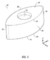
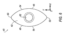
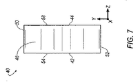
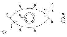
ここで図5〜図8を参照すると、切削インサート40は、第1の実質的平面42と、第2の反対側の実質的平面44とを有している。図8に示すように、第1面42の平面は、第2面44によって形成される平面に対して実質的に平行である。切削インサート40は、第1曲線側面46および第2曲線側面48と、第1曲線側面46と第2曲線側面48との間のコーナ丸み50、52とを有している。図6および図7に示すように、第1側面46および第2側面48は、形状が実質的に楕円形である。図8に示すように、コーナ丸み50によって形成される平面は、コーナ丸み52によって形成される平面に対して実質的に平行である。第1側面46および第2側面48は、第1面42および第2面44に対しておよそ90度の角度で形成されている。
Referring now to FIGS. 5-8, the
第1面42と第1側面46および第2側面48との間の交差部分に、切削エッジの第1対54、56が形成されており、第2面44と第1側面46および第2側面48との間の交差部分に、切削エッジの第2対58、60が形成されている。第1面42から第2面44まで皿穴62が延在しており、それにより、機械加工作業中に4つの切削エッジ54、56、58および60のすべてを使用することができるように、切削インサート40をインサート受入ポケット20aに取り付けることができる。
A first pair of cutting
図5〜図8に示すように、切削インサート40は、3つの中心軸、すなわちx軸、y軸およびz軸すべてを中心に鏡面対称である。特に、x軸およびy軸は、第1面42および第2面44に対して実質的に平行であり、z軸は、第1面42および第2面44に対して実質的に垂直である。この対称性により、第1面42が上面となり、第2面44が底面となりかつ底部支持面24と係合し、第1側面46および第2側面48がインサート受入ポケット20aの接触領域27、29と係合するように、切削インサート40をインサート受入ポケット20aに取り付けることができる。切削インサート40がこのように取り付けられると、切削エッジ54、56を、機械加工作業において、切削インサート40を、z軸を中心に180°回転させることによって使用することができる。さらに、第2面44が上面となり、第1面42が底面となりかつ底部支持面24と係合し、第1側面46および第2側面48がインサート受入ポケット20aの接触領域27、29と係合するように、切削インサート40をインサート受入ポケット20aに取り付けることができる。切削インサート40がこのように取り付けられると、切削エッジ58、60を、機械加工作業において、切削インサート40を、z軸を中心に180°回転させることによって使用することができる。したがって、本発明の切削インサート40は、ボールエンドミル用の従来の切削インサートで提供される2つ以下のみの切削エッジと比較して、機械加工作業で使用することができる4つの切削エッジを提供する。
As shown in FIGS. 5 to 8, the cutting
上述したように、2つの同一の切削インサートを有するボールエンドミル、各切削インサートは、ボールエンドミルに取り付けられた時にエラー防止手段を必要とすることなく任意の方向に切削することができる4つの切削エッジを有する。 As mentioned above, a ball end mill having two identical cutting inserts, each cutting insert being capable of cutting in any direction without the need for error prevention means when mounted on the ball end mill Have
本明細書で参照した文書、特許および特許出願は、参照により本明細書に援用される。 Documents, patents and patent applications referred to herein are hereby incorporated by reference.
本発明を、特に、そのいくつかの所定の実施形態に関連して説明したが、これは限定ではなく例示を目的とするものであり、添付の特許請求の範囲は、従来技術が許容する限り広範に解釈されるべきであることが理解されるべきである。 The invention has been described with particular reference to certain predetermined embodiments thereof, but this is for the purpose of illustration and not limitation, and the appended claims are intended to be as permitted by the prior art. It should be understood that this should be interpreted broadly.
Claims (21)
第1の実質的平面と、第2の実質的平面と、第1曲線側面と、第2曲線側面と、前記第1の実質的平面と前記第1曲線側面及び前記第2曲線側面との間の交差部分に形成された切削エッジの第1対と、第2の実質的平面と第1曲線側面及び第2曲線側面との間の交差部分に形成された切削エッジの第2対とを有し、
前記第1の実質的平面が、前記第2の実質的平面に対して実質的に平行である、切削インサート。 A cutting insert that can be installed in an insert receiving pocket of a ball end mill,
Between the first substantial plane, the second substantial plane, the first curved side surface, the second curved side surface, and the first substantial plane, the first curved side surface, and the second curved side surface. And a second pair of cutting edges formed at the intersection between the second substantial plane and the first curved side surface and the second curved side surface. And
The cutting insert, wherein the first substantially plane is substantially parallel to the second substantially plane.
3つの中心x軸、y軸およびz軸すべてを中心に鏡面対称であることにより、前記第1の実質的平面と前記第1曲線側面および前記第2曲線側面との間の交差部分に切削エッジの第1対を形成し、前記第2の実質的平面と前記第1曲線側面および前記第2曲線側面との間の交差部分に切削エッジの第2対を形成する、切削インサート。 A cutting insert attachable in an insert receiving pocket, the first substantial plane, the second substantial plane, the first curved side, the second curved side, the first curved side, and the first With corner roundness between two curved sides,
By being mirror-symmetrical about all three central x-, y-, and z-axes, a cutting edge at the intersection between the first substantial plane and the first curved side and the second curved side A cutting insert forming a first pair of cutting edges and forming a second pair of cutting edges at an intersection between the second substantially plane and the first curved side and the second curved side.
前記インサート受入ポケット内に取り付け可能な切削インサートであって、第1の実質的平面と、第2の実質的平面と、第1曲線側面と、第2曲線側面と、第1の実質的平面と第1曲線側面および第2曲線側面との間の交差部分に形成された切削エッジの第1対と、第2の実質的平面と第1曲線側面および第2曲線側面との間の交差部分に形成された切削エッジの第2対とを有する切削インサートと、
を具備するボールエンドミル。 A body having a substantially hemispherical front end and a rear end, wherein the substantially hemispherical front end has an insert receiving pocket, the insert receiving pocket comprising a bottom support surface, an axial support surface, A body having a radial support surface and a free surface between the axial support surface and the radial support surface;
A cutting insert attachable within the insert receiving pocket, the first substantial plane, the second substantial plane, the first curved side surface, the second curved side surface, and the first substantial plane. A first pair of cutting edges formed at an intersection between the first curved side and the second curved side; and an intersection between the second substantial plane and the first curved side and the second curved side. A cutting insert having a second pair of formed cutting edges;
A ball end mill.
前記インサート受入ポケット内に取り付け可能な切削インサートであって、第1の実質的平面と、第2の実質的平面と、前記第1の実質的平面と前記第2の実質的平面との間の第1曲線側面と、前記インサート受入ポケットの略平面接触領域のうちの少なくとも1つと係合する少なくとも1つの略平面接触領域を有する、前記第1の実質的平面と前記第2の実質的平面との間の第2曲線側面とを有する切削インサートと、
を具備するボールエンドミル。 A body having a substantially hemispherical front end and a rear end, wherein the substantially hemispherical front end has an insert receiving pocket, and the insert receiving pocket has a bottom support surface and a substantially planar contact area. A body having an axial support surface and a radial support surface having a substantially planar contact area;
A cutting insert attachable within the insert receiving pocket, between a first substantial plane, a second substantial plane, and between the first substantial plane and the second substantial plane. The first substantially planar surface and the second substantially planar surface having a first curved side surface and at least one substantially planar contact region engaging at least one of the generally planar contact regions of the insert receiving pocket; A cutting insert having a second curved side surface between,
A ball end mill.
前記インサート受入ポケット内に取り付け可能な切削インサートであって、第1の実質的平面と、第2の実質的平面と、前記第1の実質的平面と前記第2の実質的平面との間の第1曲線側面と、前記第1の実質的平面と前記第2の実質的平面との間の第2曲線側面と、凹部とを有する切削インサートと、
を具備し、
前記第1の実質的平面および前記第2の実質的平面が各々、前記インサート受入ポケットの前記多角形状突起に形状が対応する凹部を有し、それにより、前記インサート受入ポケットの前記多角形状突起が前記凹部のうちの1つと嵌合することにより、前記インサート受入ポケット内の前記切削インサートの回転移動を防止する、ボールエンドミル。 A body having a substantially hemispherical front end portion and a rear end portion, wherein the substantially hemispherical front end portion has an insert receiving pocket, and the insert receiving pocket has a bottom supporting surface from which a polygonal protrusion extends. A body having an axial support surface and a radial support surface;
A cutting insert attachable within the insert receiving pocket, between a first substantial plane, a second substantial plane, and between the first substantial plane and the second substantial plane. A cutting insert having a first curved side, a second curved side between the first and second substantially planes, and a recess;
Comprising
Each of the first substantial plane and the second substantial plane has a recess corresponding in shape to the polygonal protrusion of the insert receiving pocket, whereby the polygonal protrusion of the insert receiving pocket is A ball end mill that prevents rotational movement of the cutting insert in the insert receiving pocket by fitting with one of the recesses.
Applications Claiming Priority (3)
| Application Number | Priority Date | Filing Date | Title |
|---|---|---|---|
| US12/273,774 US9623493B2 (en) | 2008-11-19 | 2008-11-19 | Double-sided ball end mill cutting insert and tool therefor |
| US12/273,774 | 2008-11-19 | ||
| PCT/US2009/064962 WO2010059705A2 (en) | 2008-11-19 | 2009-11-18 | Double-sided ball end mill cutting insert and tool therefor |
Publications (1)
| Publication Number | Publication Date |
|---|---|
| JP2012509196A true JP2012509196A (en) | 2012-04-19 |
Family
ID=42172179
Family Applications (1)
| Application Number | Title | Priority Date | Filing Date |
|---|---|---|---|
| JP2011536617A Pending JP2012509196A (en) | 2008-11-19 | 2009-11-18 | Double-sided ball end mill cutting insert and insert tool |
Country Status (8)
| Country | Link |
|---|---|
| US (1) | US9623493B2 (en) |
| EP (1) | EP2349619A4 (en) |
| JP (1) | JP2012509196A (en) |
| KR (1) | KR20110086708A (en) |
| CN (1) | CN102216011A (en) |
| CA (1) | CA2736155A1 (en) |
| RU (1) | RU2011124897A (en) |
| WO (1) | WO2010059705A2 (en) |
Cited By (3)
| Publication number | Priority date | Publication date | Assignee | Title |
|---|---|---|---|---|
| WO2013191259A1 (en) * | 2012-06-21 | 2013-12-27 | 株式会社タンガロイ | Cutting insert, tool body on which said cutting insert may be mounted, and replaceable-blade-type ball-end mill provided therewith |
| WO2014181811A1 (en) * | 2013-05-10 | 2014-11-13 | 株式会社タンガロイ | Cutting insert, tool body on which said cutting insert can be mounted, and exchangeable edge cutting tool and ball end mill provided with same |
| JPWO2013018724A1 (en) * | 2011-07-29 | 2015-03-05 | 株式会社タンガロイ | Cutting inserts and rotary cutting tools |
Families Citing this family (21)
| Publication number | Priority date | Publication date | Assignee | Title |
|---|---|---|---|---|
| US9623493B2 (en) | 2008-11-19 | 2017-04-18 | Kennametal Inc. | Double-sided ball end mill cutting insert and tool therefor |
| KR101432000B1 (en) * | 2008-11-27 | 2014-08-20 | 대구텍 유한회사 | Double sides cutting insert and cutting tool with the same |
| SE533249C2 (en) * | 2009-03-06 | 2010-07-27 | Seco Tools Ab | Cut with recessed cutting support surface and cutting tools |
| KR101103216B1 (en) * | 2009-05-19 | 2012-01-05 | 대구텍 유한회사 | Double-sided cutting insert having a circular shape and cutting tool using the same |
| CN102458732A (en) * | 2009-06-02 | 2012-05-16 | 特固克有限会社 | Cutting insert and tool assembly comprising the same |
| IL208253A (en) | 2010-09-19 | 2015-01-29 | Iscar Ltd | Milling cutter and cutting insert therefor |
| DE102010063611A1 (en) * | 2010-12-20 | 2012-06-21 | Walter Ag | Cutting insert with structured free surfaces |
| SE535441C2 (en) * | 2010-12-28 | 2012-08-07 | Sandvik Intellectual Property | Clearing tools and head and cutters for this |
| US8647026B2 (en) * | 2011-11-23 | 2014-02-11 | Kennametal Inc. | Cutting tool with pocket feature for reducing stress |
| CN102962505B (en) * | 2012-11-12 | 2015-09-23 | 大连经济技术开发区伊达工具有限公司 | A kind of side set PCD rose cutter |
| US9475131B2 (en) * | 2013-06-13 | 2016-10-25 | Kennametal Inc. | Milling cutter with stress reliefs |
| US9475136B2 (en) * | 2013-07-30 | 2016-10-25 | Kennametal Inc. | High-speed milling cutter and cutting insert therefor |
| US9700947B2 (en) | 2014-06-27 | 2017-07-11 | Kennametal Inc. | Ballnose cutting tool and ballnose cutting insert |
| CN104400103A (en) * | 2014-11-06 | 2015-03-11 | 西安海格尔数控技术装备有限公司 | Mould surface high-speed processing and cutting device |
| US10493534B2 (en) | 2015-02-24 | 2019-12-03 | Vandurit GmbH Hartmetall und Diamantwerkzeuge | Device, method, and cutting plate for machining a rotating workpiece |
| EP3187293A1 (en) * | 2015-12-30 | 2017-07-05 | Bomar S.A. w upadlosci ukladowej | Modular screw cutter |
| DE102016104002A1 (en) * | 2016-03-04 | 2017-09-07 | Kennametal Inc. | Cutting insert for a milling cutter and milling cutter |
| US10556278B2 (en) | 2016-08-16 | 2020-02-11 | Kennametal Inc. | Tool body for a shell end mill and cutting tool |
| EP3354389A1 (en) * | 2017-01-30 | 2018-08-01 | Sandvik Intellectual Property AB | Method for machining ball tracks of constant velocity joints |
| EP3539696B1 (en) * | 2018-03-13 | 2023-10-11 | AB Sandvik Coromant | Turning tool for metal cutting comprising a coolant channel |
| CN111922400A (en) * | 2020-08-13 | 2020-11-13 | 哈尔滨汽轮机厂有限责任公司 | Method for machining steam passage fillet and conical surface of marine steam turbine blade by adopting lancet |
Family Cites Families (64)
| Publication number | Priority date | Publication date | Assignee | Title |
|---|---|---|---|---|
| US3354526A (en) | 1964-05-25 | 1967-11-28 | Futurmill Inc | Milling tool |
| US3343431A (en) | 1965-10-11 | 1967-09-26 | Donald H Boyer | Tool holder |
| US3341923A (en) | 1966-09-09 | 1967-09-19 | Gen Electric | Cutting tool |
| FR2332090A1 (en) * | 1975-11-21 | 1977-06-17 | Plansee Metallwerk | TOOL HOLDER, ESPECIALLY FOR COPY LATHES |
| JPS5349390A (en) | 1976-10-16 | 1978-05-04 | Toyota Motor Corp | Throwaway tips and end mill |
| JPS5493284A (en) | 1977-12-29 | 1979-07-24 | Sumitomo Electric Ind Ltd | Throw-away tip and end mill |
| US4220429A (en) * | 1979-04-16 | 1980-09-02 | Trw Inc. | Indexable insert drill |
| US4252480A (en) * | 1979-05-03 | 1981-02-24 | Sumitomo Electric Industries, Ltd. | Throw away insert and end mills |
| GB2070472B (en) | 1980-02-26 | 1983-06-02 | Brock & Co Ltd L & Ti | Disposable tool tip for cutting a screwthread or groove |
| DE3247138C2 (en) | 1982-12-20 | 1985-04-11 | Gühring, Gottlieb, 7470 Albstadt | Ball track milling cutter |
| US4525110A (en) * | 1983-05-18 | 1985-06-25 | Stojan Stojanovski | Indexable ball nose end mill |
| US4658875A (en) | 1986-03-24 | 1987-04-21 | Bosko Grabovac | Knife holder |
| US4729697A (en) * | 1986-06-18 | 1988-03-08 | Dijet Inc. | Milling cutter |
| DE3844787C2 (en) * | 1987-03-04 | 1992-04-23 | Mitsubishi Materials Corp., Tokio/Tokyo, Jp | |
| JPH0715686Y2 (en) * | 1987-03-04 | 1995-04-12 | 三菱マテリアル株式会社 | Ball end mill |
| DE3807195A1 (en) * | 1987-03-04 | 1988-09-15 | Mitsubishi Metal Corp | ADJUSTABLE CUTTING INSERT |
| US4919573A (en) * | 1987-09-22 | 1990-04-24 | Mitsubishi Kinzoku Kabushiki Kaisha | Ball end mill |
| JPS6450008U (en) * | 1987-09-24 | 1989-03-28 | ||
| DE3740814A1 (en) | 1987-12-02 | 1989-06-15 | Hertel Ag Werkzeuge Hartstoff | Clamping tool for cutting shaping |
| US5004378A (en) | 1988-05-19 | 1991-04-02 | Mitsubishi Metal Corporation | Clamped cutting tool |
| SE465958B (en) * | 1988-09-26 | 1991-11-25 | Sandvik Ab | DOUBLE SIDE CUT |
| JPH0247115U (en) * | 1988-09-27 | 1990-03-30 | ||
| JPH03123613A (en) | 1989-07-29 | 1991-05-27 | Ibiden Co Ltd | Filter and manufacture thereof |
| US4979849A (en) | 1989-11-20 | 1990-12-25 | Precision Industries, Inc. | Forming tool |
| US5333972A (en) * | 1990-10-04 | 1994-08-02 | Valenite Inc. | Special boring insert |
| JP2530762Y2 (en) * | 1991-03-15 | 1997-03-26 | 三菱マテリアル株式会社 | Indexable tip |
| JPH04115519U (en) * | 1991-03-28 | 1992-10-14 | 三菱マテリアル株式会社 | Throwaway ball end mill |
| US5167473A (en) * | 1991-06-24 | 1992-12-01 | Allied-Signal Inc. | Unidirectional insert lock |
| AT397626B (en) | 1992-11-20 | 1994-05-25 | Plansee Tizit Gmbh | CUTTING TOOL WITH INTEGRATED COOLANT FEED |
| SE500703C2 (en) * | 1993-01-27 | 1994-08-15 | Sandvik Ab | Cut with a recess adjacent to a twisted release surface |
| JP3166022B2 (en) * | 1993-12-28 | 2001-05-14 | 三菱マテリアル株式会社 | Indexable insert and method of manufacturing the same |
| JPH07276128A (en) * | 1994-04-12 | 1995-10-24 | Mitsubishi Materials Corp | Throwaway tip |
| IL113121A0 (en) * | 1995-03-24 | 1995-06-29 | Iscar Ltd | A cutting insert for a milling cutter |
| IL113122A0 (en) * | 1995-03-24 | 1995-06-29 | Iscar Ltd | A cutting insert |
| US5562370A (en) | 1995-03-27 | 1996-10-08 | Kennametal Inc. | Insert having sinusoidal undulations for ball nose end mill |
| SE509595C2 (en) * | 1996-01-25 | 1999-02-15 | Sandvik Ab | Cutting tool for metal cutting |
| DE19624342C1 (en) * | 1996-06-19 | 1997-12-11 | Walter Ag | Cutting insert and milling cutter, in particular ball end mill or copy milling cutter |
| KR100187562B1 (en) * | 1996-08-21 | 1999-06-01 | 최효병 | Throwaway ball endmill for finishing |
| TW363001B (en) * | 1996-11-01 | 1999-07-01 | Sumitomo Electric Industries | Multi-blades of ball end milling cutter |
| US5893683A (en) * | 1997-04-29 | 1999-04-13 | Ingersoll Cutting Tool Company | Indexable insert router |
| FR2765507A1 (en) * | 1997-07-07 | 1999-01-08 | Safety Fabrique De Carbure De | HEMISPHERIC STRAWBERRY AND PLATE FOR SUCH A STRAWBERRY |
| US6409435B1 (en) | 2000-07-03 | 2002-06-25 | Valenite Inc. | Cutting tool and method of locating cutting insert |
| KR100393618B1 (en) * | 2000-08-18 | 2003-08-02 | 삼성전자주식회사 | Channel coding/decoding apparatus and method for a cdma mobile communication system |
| IL141089A (en) * | 2001-01-25 | 2006-08-20 | Amir Satran | Cutting insert |
| DE10130200A1 (en) | 2001-06-22 | 2003-01-09 | Depo Fraestechnik Gmbh & Co Kg | End mill with indexable insert |
| IL144154A0 (en) * | 2001-07-05 | 2002-05-23 | Iscar Ltd | Cutting tool and cutting insert therefor |
| JP2003019619A (en) | 2001-07-09 | 2003-01-21 | Mitsubishi Materials Corp | Throwaway tip, and ball end mill |
| JP2003251514A (en) * | 2002-02-28 | 2003-09-09 | Hitachi Tool Engineering Ltd | Cutting edge tip replacement type ball end mill |
| JP3951766B2 (en) | 2002-03-20 | 2007-08-01 | 三菱マテリアル株式会社 | Throw-away inserts and throw-away cutting tools |
| SE525829C2 (en) * | 2002-06-26 | 2005-05-10 | Seco Tools Ab | Double sided inserts with bombed bisk cutting edge and manufacturing method for the insert |
| SE526109C2 (en) | 2003-03-17 | 2005-07-05 | Seco Tools Ab | Milling tools and indexable inserts with cooperating projections and recesses |
| US7322776B2 (en) | 2003-05-14 | 2008-01-29 | Diamond Innovations, Inc. | Cutting tool inserts and methods to manufacture |
| DE10361450A1 (en) * | 2003-12-23 | 2005-07-28 | EMUGE-Werk Richard Glimpel GmbH & Co. KG Fabrik für Präzisionswerkzeuge | Cutting element and tool with at least one cutting element |
| US7004689B2 (en) * | 2004-01-09 | 2006-02-28 | Kennametal Inc. | High-speed milling cutter and insert |
| IL160223A (en) * | 2004-02-04 | 2008-11-26 | Carol Smilovici | Double-sided cutting insert and milling cutter |
| SE528811C2 (en) | 2005-03-16 | 2007-02-20 | Sandvik Intellectual Property | Cuts and tools for chip separating machining with angled engaging means, and additives for such tools |
| SE528710C2 (en) * | 2005-06-01 | 2007-01-30 | Sandvik Intellectual Property | Indexable cutter with the coupling means arranged on a release surface |
| JP5076438B2 (en) | 2006-01-30 | 2012-11-21 | 三菱マテリアル株式会社 | Insert-type cutting tool and method of fixing insert in insert-type cutting tool |
| US7607868B2 (en) | 2006-04-24 | 2009-10-27 | Valenite Llc | Side locking insert and material removal tool with same |
| US7390150B2 (en) | 2006-05-03 | 2008-06-24 | Valenite Llc | Cutting tool with adjustable indexable cutting insert |
| ITTO20060724A1 (en) | 2006-10-09 | 2008-04-10 | Alenia Aeronautica Spa | TOOL AND MILLING METHOD, IN PARTICULAR FOR THE MILLING OF COMPOSITE MATERIALS |
| US9623493B2 (en) | 2008-11-19 | 2017-04-18 | Kennametal Inc. | Double-sided ball end mill cutting insert and tool therefor |
| US7931425B2 (en) | 2009-03-18 | 2011-04-26 | Kennametal Inc. | Cutting tool having coolant delivery system for providing cutting fluid in a fan-like pattern |
| US8858126B2 (en) | 2009-09-25 | 2014-10-14 | Kennametal Inc. | Cutting tool with error proofing feature |
-
2008
- 2008-11-19 US US12/273,774 patent/US9623493B2/en active Active
-
2009
- 2009-11-18 KR KR1020117011235A patent/KR20110086708A/en not_active Application Discontinuation
- 2009-11-18 WO PCT/US2009/064962 patent/WO2010059705A2/en active Application Filing
- 2009-11-18 RU RU2011124897/02A patent/RU2011124897A/en unknown
- 2009-11-18 EP EP09828155A patent/EP2349619A4/en not_active Withdrawn
- 2009-11-18 CA CA2736155A patent/CA2736155A1/en not_active Abandoned
- 2009-11-18 JP JP2011536617A patent/JP2012509196A/en active Pending
- 2009-11-18 CN CN2009801458279A patent/CN102216011A/en active Pending
Cited By (5)
| Publication number | Priority date | Publication date | Assignee | Title |
|---|---|---|---|---|
| JPWO2013018724A1 (en) * | 2011-07-29 | 2015-03-05 | 株式会社タンガロイ | Cutting inserts and rotary cutting tools |
| WO2013191259A1 (en) * | 2012-06-21 | 2013-12-27 | 株式会社タンガロイ | Cutting insert, tool body on which said cutting insert may be mounted, and replaceable-blade-type ball-end mill provided therewith |
| JP5825435B2 (en) * | 2012-06-21 | 2015-12-02 | 株式会社タンガロイ | Cutting insert, tool main body to which the cutting insert can be mounted, and a blade end replaceable ball end mill provided with the same |
| WO2014181811A1 (en) * | 2013-05-10 | 2014-11-13 | 株式会社タンガロイ | Cutting insert, tool body on which said cutting insert can be mounted, and exchangeable edge cutting tool and ball end mill provided with same |
| JPWO2014181811A1 (en) * | 2013-05-10 | 2017-02-23 | 株式会社タンガロイ | Cutting insert, tool body to which the cutting insert can be mounted, cutting edge-exchangeable cutting tool and ball end mill provided with the same |
Also Published As
| Publication number | Publication date |
|---|---|
| US20100124465A1 (en) | 2010-05-20 |
| CA2736155A1 (en) | 2010-05-27 |
| EP2349619A2 (en) | 2011-08-03 |
| US9623493B2 (en) | 2017-04-18 |
| KR20110086708A (en) | 2011-07-29 |
| WO2010059705A3 (en) | 2010-09-16 |
| CN102216011A (en) | 2011-10-12 |
| RU2011124897A (en) | 2012-12-27 |
| WO2010059705A2 (en) | 2010-05-27 |
| EP2349619A4 (en) | 2012-05-09 |
Similar Documents
| Publication | Publication Date | Title |
|---|---|---|
| JP2012509196A (en) | Double-sided ball end mill cutting insert and insert tool | |
| JP4327605B2 (en) | Metal cutting tools | |
| US8529168B2 (en) | Cutting insert with a wiper edge | |
| US20060056928A1 (en) | Indexable insert with corners with different radii | |
| MX2007014484A (en) | Cutting insert, in particular, for crankshaft machining. | |
| CN108778589B (en) | Cutting insert, tool holder and tool | |
| KR20150030217A (en) | Rotary cutting tool and reversible cutting insert therefor | |
| KR101556832B1 (en) | Milling cutter and cutting insert having rear protuberance therefor | |
| WO2016096180A1 (en) | Reinforced double-sided cutting insert and cutting tool with reinforced double-sided cutting insert | |
| JP2015523228A (en) | Cutting insert and cutting tool including the same | |
| US10350689B2 (en) | Double-sided circular cutting insert and indexable rotary cutting tool | |
| JP2007021622A (en) | Tip and milling tool | |
| KR102554780B1 (en) | Square-shaped cutting inserts and rotary cutting tools with curved secondary cutting edges and corner cutting edges | |
| EP2502691B1 (en) | Cutting insert and cutting tool | |
| KR20210125508A (en) | A rotary cutting body having an insert pocket having a seat surface provided with a plurality of adjacent elements, a rotary cutting tool and an insert. | |
| JP6717962B2 (en) | Cutting inserts, tool holders and tools for machining workpieces | |
| EP3970892A1 (en) | Cutting insert | |
| JP6972510B2 (en) | Cutting insert | |
| JP6048632B1 (en) | Double-sided circular cutting insert and cutting edge exchangeable rotary cutting tool | |
| US20210245258A1 (en) | Square-shaped insert for bar-peeling and insert-holder tool for same | |
| JP2007021658A (en) | Milling tool and high-feed tip | |
| KR20230065973A (en) | Wiper inserts and indexable edge milling cutters |