JP2012509116A - Articulating disc prosthesis - Google Patents
Articulating disc prosthesis Download PDFInfo
- Publication number
- JP2012509116A JP2012509116A JP2011536710A JP2011536710A JP2012509116A JP 2012509116 A JP2012509116 A JP 2012509116A JP 2011536710 A JP2011536710 A JP 2011536710A JP 2011536710 A JP2011536710 A JP 2011536710A JP 2012509116 A JP2012509116 A JP 2012509116A
- Authority
- JP
- Japan
- Prior art keywords
- intervertebral disc
- shell
- lower shell
- disc
- movement
- Prior art date
- Legal status (The legal status is an assumption and is not a legal conclusion. Google has not performed a legal analysis and makes no representation as to the accuracy of the status listed.)
- Pending
Links
Images


Classifications
-
- A—HUMAN NECESSITIES
- A61—MEDICAL OR VETERINARY SCIENCE; HYGIENE
- A61F—FILTERS IMPLANTABLE INTO BLOOD VESSELS; PROSTHESES; DEVICES PROVIDING PATENCY TO, OR PREVENTING COLLAPSING OF, TUBULAR STRUCTURES OF THE BODY, e.g. STENTS; ORTHOPAEDIC, NURSING OR CONTRACEPTIVE DEVICES; FOMENTATION; TREATMENT OR PROTECTION OF EYES OR EARS; BANDAGES, DRESSINGS OR ABSORBENT PADS; FIRST-AID KITS
- A61F2/00—Filters implantable into blood vessels; Prostheses, i.e. artificial substitutes or replacements for parts of the body; Appliances for connecting them with the body; Devices providing patency to, or preventing collapsing of, tubular structures of the body, e.g. stents
- A61F2/02—Prostheses implantable into the body
- A61F2/30—Joints
- A61F2/44—Joints for the spine, e.g. vertebrae, spinal discs
-
- A—HUMAN NECESSITIES
- A61—MEDICAL OR VETERINARY SCIENCE; HYGIENE
- A61B—DIAGNOSIS; SURGERY; IDENTIFICATION
- A61B17/00—Surgical instruments, devices or methods, e.g. tourniquets
- A61B17/56—Surgical instruments or methods for treatment of bones or joints; Devices specially adapted therefor
- A61B17/58—Surgical instruments or methods for treatment of bones or joints; Devices specially adapted therefor for osteosynthesis, e.g. bone plates, screws, setting implements or the like
- A61B17/68—Internal fixation devices, including fasteners and spinal fixators, even if a part thereof projects from the skin
- A61B17/70—Spinal positioners or stabilisers ; Bone stabilisers comprising fluid filler in an implant
-
- A—HUMAN NECESSITIES
- A61—MEDICAL OR VETERINARY SCIENCE; HYGIENE
- A61F—FILTERS IMPLANTABLE INTO BLOOD VESSELS; PROSTHESES; DEVICES PROVIDING PATENCY TO, OR PREVENTING COLLAPSING OF, TUBULAR STRUCTURES OF THE BODY, e.g. STENTS; ORTHOPAEDIC, NURSING OR CONTRACEPTIVE DEVICES; FOMENTATION; TREATMENT OR PROTECTION OF EYES OR EARS; BANDAGES, DRESSINGS OR ABSORBENT PADS; FIRST-AID KITS
- A61F2/00—Filters implantable into blood vessels; Prostheses, i.e. artificial substitutes or replacements for parts of the body; Appliances for connecting them with the body; Devices providing patency to, or preventing collapsing of, tubular structures of the body, e.g. stents
- A61F2/02—Prostheses implantable into the body
- A61F2/30—Joints
- A61F2/44—Joints for the spine, e.g. vertebrae, spinal discs
- A61F2/442—Intervertebral or spinal discs, e.g. resilient
- A61F2/4425—Intervertebral or spinal discs, e.g. resilient made of articulated components
-
- A—HUMAN NECESSITIES
- A61—MEDICAL OR VETERINARY SCIENCE; HYGIENE
- A61B—DIAGNOSIS; SURGERY; IDENTIFICATION
- A61B17/00—Surgical instruments, devices or methods, e.g. tourniquets
- A61B17/32—Surgical cutting instruments
-
- A—HUMAN NECESSITIES
- A61—MEDICAL OR VETERINARY SCIENCE; HYGIENE
- A61F—FILTERS IMPLANTABLE INTO BLOOD VESSELS; PROSTHESES; DEVICES PROVIDING PATENCY TO, OR PREVENTING COLLAPSING OF, TUBULAR STRUCTURES OF THE BODY, e.g. STENTS; ORTHOPAEDIC, NURSING OR CONTRACEPTIVE DEVICES; FOMENTATION; TREATMENT OR PROTECTION OF EYES OR EARS; BANDAGES, DRESSINGS OR ABSORBENT PADS; FIRST-AID KITS
- A61F2/00—Filters implantable into blood vessels; Prostheses, i.e. artificial substitutes or replacements for parts of the body; Appliances for connecting them with the body; Devices providing patency to, or preventing collapsing of, tubular structures of the body, e.g. stents
- A61F2/02—Prostheses implantable into the body
- A61F2/30—Joints
- A61F2/30767—Special external or bone-contacting surface, e.g. coating for improving bone ingrowth
- A61F2/30771—Special external or bone-contacting surface, e.g. coating for improving bone ingrowth applied in original prostheses, e.g. holes or grooves
-
- A—HUMAN NECESSITIES
- A61—MEDICAL OR VETERINARY SCIENCE; HYGIENE
- A61F—FILTERS IMPLANTABLE INTO BLOOD VESSELS; PROSTHESES; DEVICES PROVIDING PATENCY TO, OR PREVENTING COLLAPSING OF, TUBULAR STRUCTURES OF THE BODY, e.g. STENTS; ORTHOPAEDIC, NURSING OR CONTRACEPTIVE DEVICES; FOMENTATION; TREATMENT OR PROTECTION OF EYES OR EARS; BANDAGES, DRESSINGS OR ABSORBENT PADS; FIRST-AID KITS
- A61F2/00—Filters implantable into blood vessels; Prostheses, i.e. artificial substitutes or replacements for parts of the body; Appliances for connecting them with the body; Devices providing patency to, or preventing collapsing of, tubular structures of the body, e.g. stents
- A61F2/02—Prostheses implantable into the body
- A61F2/30—Joints
- A61F2002/30001—Additional features of subject-matter classified in A61F2/28, A61F2/30 and subgroups thereof
- A61F2002/30108—Shapes
- A61F2002/3011—Cross-sections or two-dimensional shapes
- A61F2002/30112—Rounded shapes, e.g. with rounded corners
- A61F2002/30125—Rounded shapes, e.g. with rounded corners elliptical or oval
-
- A—HUMAN NECESSITIES
- A61—MEDICAL OR VETERINARY SCIENCE; HYGIENE
- A61F—FILTERS IMPLANTABLE INTO BLOOD VESSELS; PROSTHESES; DEVICES PROVIDING PATENCY TO, OR PREVENTING COLLAPSING OF, TUBULAR STRUCTURES OF THE BODY, e.g. STENTS; ORTHOPAEDIC, NURSING OR CONTRACEPTIVE DEVICES; FOMENTATION; TREATMENT OR PROTECTION OF EYES OR EARS; BANDAGES, DRESSINGS OR ABSORBENT PADS; FIRST-AID KITS
- A61F2/00—Filters implantable into blood vessels; Prostheses, i.e. artificial substitutes or replacements for parts of the body; Appliances for connecting them with the body; Devices providing patency to, or preventing collapsing of, tubular structures of the body, e.g. stents
- A61F2/02—Prostheses implantable into the body
- A61F2/30—Joints
- A61F2002/30001—Additional features of subject-matter classified in A61F2/28, A61F2/30 and subgroups thereof
- A61F2002/30108—Shapes
- A61F2002/3011—Cross-sections or two-dimensional shapes
- A61F2002/30112—Rounded shapes, e.g. with rounded corners
- A61F2002/30131—Rounded shapes, e.g. with rounded corners horseshoe- or crescent- or C-shaped or U-shaped
-
- A—HUMAN NECESSITIES
- A61—MEDICAL OR VETERINARY SCIENCE; HYGIENE
- A61F—FILTERS IMPLANTABLE INTO BLOOD VESSELS; PROSTHESES; DEVICES PROVIDING PATENCY TO, OR PREVENTING COLLAPSING OF, TUBULAR STRUCTURES OF THE BODY, e.g. STENTS; ORTHOPAEDIC, NURSING OR CONTRACEPTIVE DEVICES; FOMENTATION; TREATMENT OR PROTECTION OF EYES OR EARS; BANDAGES, DRESSINGS OR ABSORBENT PADS; FIRST-AID KITS
- A61F2/00—Filters implantable into blood vessels; Prostheses, i.e. artificial substitutes or replacements for parts of the body; Appliances for connecting them with the body; Devices providing patency to, or preventing collapsing of, tubular structures of the body, e.g. stents
- A61F2/02—Prostheses implantable into the body
- A61F2/30—Joints
- A61F2002/30001—Additional features of subject-matter classified in A61F2/28, A61F2/30 and subgroups thereof
- A61F2002/30108—Shapes
- A61F2002/3011—Cross-sections or two-dimensional shapes
- A61F2002/30182—Other shapes
- A61F2002/30187—D-shaped or half-disc-shaped
-
- A—HUMAN NECESSITIES
- A61—MEDICAL OR VETERINARY SCIENCE; HYGIENE
- A61F—FILTERS IMPLANTABLE INTO BLOOD VESSELS; PROSTHESES; DEVICES PROVIDING PATENCY TO, OR PREVENTING COLLAPSING OF, TUBULAR STRUCTURES OF THE BODY, e.g. STENTS; ORTHOPAEDIC, NURSING OR CONTRACEPTIVE DEVICES; FOMENTATION; TREATMENT OR PROTECTION OF EYES OR EARS; BANDAGES, DRESSINGS OR ABSORBENT PADS; FIRST-AID KITS
- A61F2/00—Filters implantable into blood vessels; Prostheses, i.e. artificial substitutes or replacements for parts of the body; Appliances for connecting them with the body; Devices providing patency to, or preventing collapsing of, tubular structures of the body, e.g. stents
- A61F2/02—Prostheses implantable into the body
- A61F2/30—Joints
- A61F2002/30001—Additional features of subject-matter classified in A61F2/28, A61F2/30 and subgroups thereof
- A61F2002/30316—The prosthesis having different structural features at different locations within the same prosthesis; Connections between prosthetic parts; Special structural features of bone or joint prostheses not otherwise provided for
- A61F2002/30535—Special structural features of bone or joint prostheses not otherwise provided for
- A61F2002/30563—Special structural features of bone or joint prostheses not otherwise provided for having elastic means or damping means, different from springs, e.g. including an elastomeric core or shock absorbers
-
- A—HUMAN NECESSITIES
- A61—MEDICAL OR VETERINARY SCIENCE; HYGIENE
- A61F—FILTERS IMPLANTABLE INTO BLOOD VESSELS; PROSTHESES; DEVICES PROVIDING PATENCY TO, OR PREVENTING COLLAPSING OF, TUBULAR STRUCTURES OF THE BODY, e.g. STENTS; ORTHOPAEDIC, NURSING OR CONTRACEPTIVE DEVICES; FOMENTATION; TREATMENT OR PROTECTION OF EYES OR EARS; BANDAGES, DRESSINGS OR ABSORBENT PADS; FIRST-AID KITS
- A61F2/00—Filters implantable into blood vessels; Prostheses, i.e. artificial substitutes or replacements for parts of the body; Appliances for connecting them with the body; Devices providing patency to, or preventing collapsing of, tubular structures of the body, e.g. stents
- A61F2/02—Prostheses implantable into the body
- A61F2/30—Joints
- A61F2002/30001—Additional features of subject-matter classified in A61F2/28, A61F2/30 and subgroups thereof
- A61F2002/30621—Features concerning the anatomical functioning or articulation of the prosthetic joint
- A61F2002/30649—Ball-and-socket joints
- A61F2002/30662—Ball-and-socket joints with rotation-limiting means
-
- A—HUMAN NECESSITIES
- A61—MEDICAL OR VETERINARY SCIENCE; HYGIENE
- A61F—FILTERS IMPLANTABLE INTO BLOOD VESSELS; PROSTHESES; DEVICES PROVIDING PATENCY TO, OR PREVENTING COLLAPSING OF, TUBULAR STRUCTURES OF THE BODY, e.g. STENTS; ORTHOPAEDIC, NURSING OR CONTRACEPTIVE DEVICES; FOMENTATION; TREATMENT OR PROTECTION OF EYES OR EARS; BANDAGES, DRESSINGS OR ABSORBENT PADS; FIRST-AID KITS
- A61F2/00—Filters implantable into blood vessels; Prostheses, i.e. artificial substitutes or replacements for parts of the body; Appliances for connecting them with the body; Devices providing patency to, or preventing collapsing of, tubular structures of the body, e.g. stents
- A61F2/02—Prostheses implantable into the body
- A61F2/30—Joints
- A61F2/44—Joints for the spine, e.g. vertebrae, spinal discs
- A61F2/442—Intervertebral or spinal discs, e.g. resilient
- A61F2/4425—Intervertebral or spinal discs, e.g. resilient made of articulated components
- A61F2002/443—Intervertebral or spinal discs, e.g. resilient made of articulated components having two transversal endplates and at least one intermediate component
-
- A—HUMAN NECESSITIES
- A61—MEDICAL OR VETERINARY SCIENCE; HYGIENE
- A61F—FILTERS IMPLANTABLE INTO BLOOD VESSELS; PROSTHESES; DEVICES PROVIDING PATENCY TO, OR PREVENTING COLLAPSING OF, TUBULAR STRUCTURES OF THE BODY, e.g. STENTS; ORTHOPAEDIC, NURSING OR CONTRACEPTIVE DEVICES; FOMENTATION; TREATMENT OR PROTECTION OF EYES OR EARS; BANDAGES, DRESSINGS OR ABSORBENT PADS; FIRST-AID KITS
- A61F2230/00—Geometry of prostheses classified in groups A61F2/00 - A61F2/26 or A61F2/82 or A61F9/00 or A61F11/00 or subgroups thereof
- A61F2230/0002—Two-dimensional shapes, e.g. cross-sections
- A61F2230/0004—Rounded shapes, e.g. with rounded corners
- A61F2230/0008—Rounded shapes, e.g. with rounded corners elliptical or oval
-
- A—HUMAN NECESSITIES
- A61—MEDICAL OR VETERINARY SCIENCE; HYGIENE
- A61F—FILTERS IMPLANTABLE INTO BLOOD VESSELS; PROSTHESES; DEVICES PROVIDING PATENCY TO, OR PREVENTING COLLAPSING OF, TUBULAR STRUCTURES OF THE BODY, e.g. STENTS; ORTHOPAEDIC, NURSING OR CONTRACEPTIVE DEVICES; FOMENTATION; TREATMENT OR PROTECTION OF EYES OR EARS; BANDAGES, DRESSINGS OR ABSORBENT PADS; FIRST-AID KITS
- A61F2230/00—Geometry of prostheses classified in groups A61F2/00 - A61F2/26 or A61F2/82 or A61F9/00 or A61F11/00 or subgroups thereof
- A61F2230/0002—Two-dimensional shapes, e.g. cross-sections
- A61F2230/0004—Rounded shapes, e.g. with rounded corners
- A61F2230/0013—Horseshoe-shaped, e.g. crescent-shaped, C-shaped, U-shaped
-
- A—HUMAN NECESSITIES
- A61—MEDICAL OR VETERINARY SCIENCE; HYGIENE
- A61F—FILTERS IMPLANTABLE INTO BLOOD VESSELS; PROSTHESES; DEVICES PROVIDING PATENCY TO, OR PREVENTING COLLAPSING OF, TUBULAR STRUCTURES OF THE BODY, e.g. STENTS; ORTHOPAEDIC, NURSING OR CONTRACEPTIVE DEVICES; FOMENTATION; TREATMENT OR PROTECTION OF EYES OR EARS; BANDAGES, DRESSINGS OR ABSORBENT PADS; FIRST-AID KITS
- A61F2230/00—Geometry of prostheses classified in groups A61F2/00 - A61F2/26 or A61F2/82 or A61F9/00 or A61F11/00 or subgroups thereof
- A61F2230/0002—Two-dimensional shapes, e.g. cross-sections
- A61F2230/0028—Shapes in the form of latin or greek characters
- A61F2230/0034—D-shaped
Abstract
2つの隣接する椎骨間に埋め込む人工椎間板が、ボールソケット構成で接続される上側シェル及び下側シェルを備える。下側シェルは好ましくは、上側シェルの凹部分と協働する凸部分を組み入れている。弾性核が、それらのシェルの対向する内面によって画定されるエンクロージャー内に設けられており、シェルを互いに対して付勢する。ボール部分を固定構成又は摺動可能な構成で設けることができる。上側シェル及び下側シェルには協働する雄型部分及び雌型部分も設けられることで、それらのシェルが互いに確実に係合し、それにより分離が防止されるが、それらのシェル間に任意の所望の関節運動を可能にする。本発明の人工椎間板は、それらのシェル間の回転及び並進運動の範囲を限定及び制限する様々な抵抗手段を有する。
【選択図】図22An artificial disc that is implanted between two adjacent vertebrae comprises an upper shell and a lower shell connected in a ball socket configuration. The lower shell preferably incorporates a convex portion that cooperates with the concave portion of the upper shell. Elastic nuclei are provided within the enclosure defined by the opposing inner surfaces of the shells and bias the shells against each other. The ball portion can be provided in a fixed configuration or a slidable configuration. The upper and lower shells are also provided with cooperating male and female parts that ensure that the shells engage each other and thereby prevent separation, but any Allowing the desired joint movement. The artificial disc of the present invention has various resistance means that limit and limit the range of rotational and translational motion between the shells.
[Selection] Figure 22
Description
本発明は脊椎インプラントの分野に関し、より詳細には、様々な程度の関節運動(articulation)を可能にする椎間板プロテーゼに関する。 The present invention relates to the field of spinal implants, and more particularly to an intervertebral disc prosthesis that allows for varying degrees of articulation.
[先願の相互参照]
本願は、米国仮出願第60/934,277号(2007年6月12日に出願)からの優先権を主張するPCT出願PCT/CA2008/001114号(2008年6月12日に出願)の一部継続である米国特許出願第12/274,685号(2008年11月20日に出願)からの優先権を主張する。上記の先願の内容は全て参照により本明細書に援用される。
[Cross-reference of prior application]
This application is a part of PCT application PCT / CA2008 / 001114 (filed on Jun. 12, 2008) claiming priority from US Provisional Application No. 60 / 934,277 (filed on Jun. 12, 2007). Claims priority from US patent application Ser. No. 12 / 274,685, filed Nov. 20, 2008, which is a continuation of the department. The contents of the above-mentioned prior applications are all incorporated herein by reference.
脊柱は、様々な解剖学的構成要素からなる複雑な構造であるが、一方で非常に柔軟であり、身体に構造及び安定性をもたらす。脊柱は、実質的に円柱状の椎体をそれぞれが有する椎骨から構成される。隣接する椎体の対向面は、線維軟骨物質からなる椎間板によって、共に連結及び分離されている。椎体はまた、過度な運動を制限し安定性を与えるように共に作用する靱帯の複雑な構成によって、互いに連結されている。 The spinal column is a complex structure consisting of various anatomical components, but on the other hand it is very flexible and provides structure and stability to the body. The spinal column is composed of vertebrae each having a substantially cylindrical vertebral body. The opposing surfaces of adjacent vertebral bodies are connected and separated together by an intervertebral disc made of fibrocartilage material. The vertebral bodies are also connected to each other by a complex configuration of ligaments that work together to limit excessive movement and provide stability.
椎間板の主な機能は、荷重支持(荷重分配及び衝撃吸収を含む)及び動きである。その重量支持機能により、椎間板は隣接する椎体間にクッションをもたらしつつ、1つの椎体から次の椎体へ荷重を伝達する。椎間板はまた、隣接する椎体間に限定範囲内ではあるが運動を生じさせることで、脊柱に構造及び剛性を与える。このような運動は、正及び負の方向の並進及び回転、並びにそれらの多くの組合せを含む。したがって、椎間板は、隣接する椎骨間に生じる様々な複雑な運動、すなわち、関節運動を可能にする。 The main functions of the intervertebral disc are load support (including load distribution and shock absorption) and movement. Due to its weight support function, the intervertebral disc transmits a load from one vertebral body to the next while providing a cushion between adjacent vertebral bodies. The intervertebral disc also provides structure and stiffness to the spinal column by creating motion, albeit in a limited range, between adjacent vertebral bodies. Such motion includes translation and rotation in the positive and negative directions, and many combinations thereof. Thus, the intervertebral disc allows for various complex movements that occur between adjacent vertebrae, ie, articulation.
例えば、年齢、外傷、疾患等の多くの要因により、多くの場合、椎間板がその寸法安定性を失い、圧潰し、萎縮し、変位状態又は他の損傷状態になることが判明している。当該技術分野において知られているように、罹患又は損傷した椎間板は、プロテーゼ及びそのようなプロテーゼの様々な変形物又はインプラントで置換することが通例である。既知の方法の1つは、損傷した椎間板を、該椎間板が占めている空間内に入るスペーサーで置換することを含む。しかしながら、そのようなスペーサーは、隣接する椎骨も一緒に結合することで、それらの椎骨間でのいかなる相対運動も妨げてしまう。 For example, due to many factors such as age, trauma, disease, etc., it has often been found that the intervertebral disc loses its dimensional stability, collapses, contracts, becomes displaced or otherwise damaged. As is known in the art, affected or damaged discs are typically replaced with prostheses and various variants or implants of such prostheses. One known method involves replacing a damaged disc with a spacer that falls within the space occupied by the disc. However, such spacers also join adjacent vertebrae together, preventing any relative movement between those vertebrae.
最近、隣接する椎骨間の運動を可能にする椎間板置換インプラントが提案されている。先行技術による幾つかのインプラントの例が、以下の米国特許、すなわち、特許文献1(Boyd他)、特許文献2(Cauthen)及び特許文献3(Simonson)において提示されている。 Recently, disc replacement implants have been proposed that allow movement between adjacent vertebrae. Some examples of prior art implants are presented in the following US patents: US Pat. Nos. 5,099,086 (Boyd et al.), US Pat.
上述した人工椎間板の他に、本発明者らは、種々の椎間運動を提供する様々な改善された椎間板プロテーゼ、及び本来の脊椎構造に見られるような通常の動きの制限をシミュレートする手段を提案している。本発明者らの椎間板プロテーゼの例は、以下の米国特許出願、すなわち、特許文献4、特許文献5及び特許文献6に記載されている。これらの先願はその全体が参照により本明細書に援用される。 In addition to the artificial discs described above, we have various improved intervertebral disc prostheses that provide various intervertebral movements, and a means to simulate normal movement limitations as found in native spinal structures. Has proposed. Examples of our intervertebral disc prostheses are described in the following US patent applications: US Pat. These prior applications are incorporated herein by reference in their entirety.
人工椎間板を開発する上で、椎間板構成要素の分離及び/又は任意の所与の方向への極端な動きを防止しつつも椎間板に広範の関節運動を可能にすることが望まれている。 In developing an artificial disc, it is desirable to allow a wide range of articulation of the disc while preventing separation of the disc components and / or extreme movement in any given direction.
一態様では、本発明は、椎間板を置換するインプラントを提供する。 In one aspect, the present invention provides an implant for replacing an intervertebral disc.
別の態様では、本発明は、隣接する椎骨に様々な平面内の動きの範囲(a range of motions:可動域)を可能にする人工椎間板を提供する。そのような動きは、隣接する椎骨の動きが隣の脊椎構造構成要素の劣化につながらない所定範囲内に制限することができる。 In another aspect, the present invention provides an artificial disc that allows a range of motions in adjacent planes of vertebrae. Such movement can be limited to a predetermined range in which movement of adjacent vertebrae does not lead to degradation of adjacent spinal structure components.
別の態様では、様々な軸を中心とした上記の動きを合わせて、自然な動きをより厳密にシミュレートすることができる。 In another aspect, the above movements about various axes can be combined to more closely simulate natural movement.
別の実施の形態では、本発明は、椎間板を形成する2つの主要な構成要素の分離を防止する手段を含む人工椎間板を提供する。 In another embodiment, the present invention provides a prosthetic disc that includes means for preventing the separation of the two major components forming the disc.
したがって、一態様では、本発明は、脊椎の隣接する上の椎骨及び下の椎骨間に埋め込む人工椎間板であって、該椎間板は、
上側シェルと、下側シェルと、該上側シェル及び該下側シェルを離すように付勢する手段とを備え、
該上側シェル及び該下側シェルは、2つ以上の関節運動面により互いに対して可動であり、
該下側シェルは、後方に位置する凸部分を含む上面を有し、
該上側シェルは、該下側シェルの該上面に対向すると共に、該凸部分に対向する後方に位置する凹部分を含む下面を有し、
該凸部分及び該凹部分は、ボールソケットジョイント(joint:接合部)を形成するように関節運動式に協働し、
該凸部分又は該凹部分の少なくとも一方は、少なくとも1つの雄型部分を有し、該凸部分又は該凹部分の他方は、該少なくとも1つの雄型部分を受け入れると共に該雄型部分と確実に係合するように構成された対応する数の協働する雌型部分を有する。
Thus, in one aspect, the invention provides an artificial disc that is implanted between adjacent upper and lower vertebrae of the spine, the disc being
An upper shell, a lower shell, and means for biasing the upper shell and the lower shell apart,
The upper shell and the lower shell are movable relative to each other by two or more articulating surfaces;
The lower shell has an upper surface including a convex portion located at the rear,
The upper shell is opposed to the upper surface of the lower shell, and has a lower surface including a concave portion located in the rear facing the convex portion,
The convex portion and the concave portion cooperate in an articulated manner so as to form a ball socket joint (joint),
At least one of the convex portion or the concave portion has at least one male portion, and the other of the convex portion or the concave portion receives the at least one male portion and is securely connected to the male portion. It has a corresponding number of cooperating female molds configured to engage.
本発明の特徴は、添付の図面を参照する以下の詳細な説明においてより明らかとなるであろう。 The features of the present invention will become more apparent in the following detailed description when taken in conjunction with the accompanying drawings.
以下の説明において、「上(側)」、「下(側)」、「前方」、「後方」及び「側方」という用語を使用する。これらの用語は、脊椎内に位置付けされるときの本発明のインプラントの向きを説明することを意図する。したがって、「上(側)」は上部を指し、「後方」は、脊椎が直立位置にあるときに、インプラント(又は他の脊柱構成要素)の、患者の身体の背面に面する部分を指す。同様に、「下(側)」という用語はインプラントの下部を指すのに用いられ、「前方」は、脊椎が直立位置にあるときに、患者の身体の正面に面する部分を指すのに用いられる。添付の図面に示されている図に関して、「冠状面」という用語は、側方端間に延びることで身体を前方部分と後方部分に分離する面を示すことが理解されるであろう。「矢状面」という用語は、前後方向に延びることで身体を2つの側方部分に分離する面を示すことが理解されるであろう。「軸面」という用語は、身体を上側部分及び下側部分に分離する面を示すことが理解されるであろう。これらの位置及び向きに関する用語は、本発明をいずれかの特定の向きに限定することを意図するものではなく、以下の説明を容易にするために用いられることが分かるであろう。 In the following description, the terms “upper (side)”, “lower (side)”, “front”, “rear”, and “lateral” are used. These terms are intended to describe the orientation of the implant of the present invention when positioned within the spine. Thus, “upper” refers to the top and “posterior” refers to the portion of the implant (or other spinal component) that faces the back of the patient's body when the spine is in an upright position. Similarly, the term “bottom” is used to refer to the lower portion of the implant, and “anterior” is used to refer to the front facing portion of the patient's body when the spine is in an upright position. It is done. With reference to the figures shown in the accompanying drawings, it will be understood that the term “coronal surface” refers to a surface that extends between the lateral ends and separates the body into an anterior portion and a posterior portion. It will be appreciated that the term “sagittal plane” refers to a plane that extends in the anterior-posterior direction to separate the body into two lateral portions. It will be appreciated that the term “axial surface” refers to a surface that separates the body into an upper part and a lower part. It will be appreciated that these position and orientation terms are not intended to limit the invention to any particular orientation, but are used to facilitate the following description.
本発明は、損傷したか又は他の機能不全となった椎間板を置換するための人工椎間板又はインプラントを提供する。本発明のインプラントは、隣接する椎体間の様々な程度の動きを許容限界内ではあるが可能にするように設計される。 The present invention provides an artificial disc or implant for replacing a damaged or other dysfunctional disc. The implants of the present invention are designed to allow varying degrees of movement between adjacent vertebral bodies, albeit within acceptable limits.
図1は、椎骨に関連する様々な自由度を示すことによって椎骨の動きの複雑性を示す。生理学的な動きの正常範囲では、椎骨は「中立領域」と「弾性領域」との間に延びる。中立領域は、動きの全範囲内の領域であり、この領域では、脊椎の骨構造を支持する靭帯は比較的応力を受けない、すなわち、靭帯が動きに対して与える抵抗は比較的小さい。動きの範囲の限界地点又は限界付近で動きが生じる場合に弾性領域に遭遇する。この領域では、靭帯の粘弾性的性質が動きに対して抵抗を示し始めることで動きを制限する。「毎日の」又は通常の動きの大部分は中立領域内で生じ、弾性領域に及ぶことはごく稀である。中立領域内に含まれる動きは軟組織構造に応力を与えないが、弾性領域への動きは様々な程度の弾性応答を引き起こす。したがって、特に脊椎の人工インプラントの分野における目標は、そこに隣接する椎骨の動きを中立領域に制限するプロテーゼを提供することである。そのような制限により、隣接する骨構造及び軟組織構造に対する応力を最小限にする。例えば、そのような動きの制限は椎間関節変性を最小限にするか又は減らすのに役立つ。 FIG. 1 illustrates the complexity of vertebral movement by showing the various degrees of freedom associated with the vertebrae. In the normal range of physiological movement, the vertebrae extend between a “neutral region” and an “elastic region”. The neutral region is the region within the full range of motion, in which the ligaments that support the vertebral bone structure are relatively unstressed, i.e., the resistance the ligaments impart to motion is relatively small. An elastic region is encountered when motion occurs near or near the limit of the range of motion. In this region, movement is limited by the viscoelastic nature of the ligaments beginning to show resistance to movement. Most of the “daily” or normal movement occurs in the neutral region and rarely extends into the elastic region. While movements contained within the neutral region do not stress the soft tissue structure, movements into the elastic region cause varying degrees of elastic response. Thus, a goal, particularly in the field of spinal prosthetic implants, is to provide a prosthesis that restricts movement of adjacent vertebrae to a neutral region. Such limitations minimize stress on adjacent bone and soft tissue structures. For example, such movement limitation helps to minimize or reduce facet joint degeneration.
包括的に、本発明は椎間板を置換するための埋め込み式脊椎プロテーゼを提供する。本発明のインプラントは概して、協働する下側部分及び上側部分、すなわち、下側シェル及び上側シェルからなり、これらは互いに対して可動であり、力を吸収する弾性核によってその少なくとも一部に沿って分離されている。本発明の椎間板の構成要素間の相対運動は様々な自由度を有するが、概して特定範囲に制限される。すなわち、プロテーゼには、それに隣接する椎骨間の動きを制限するための様々な「緩やかな」停止機構及び「急な」停止機構が与えられる。特に、本発明の人工椎間板は、中立領域及び弾性領域における正常な運動に類似した回転、屈曲、伸展及び側方運動(すなわち、正常又は無傷の椎間板に関連する運動)を提供する。さらに、本発明の装置はそのような動きの様々な組合せ、すなわち複合運動(coupled motion)も可能にする。例えば、本発明の椎間板は屈曲及び並進、又は側屈及び側方並進、又は屈曲及び回転を受けることができる。本開示を鑑み、様々な他の動きが当業者には明らかであろう。 In general, the present invention provides an implantable spinal prosthesis for replacing an intervertebral disc. The implants of the present invention generally consist of cooperating lower and upper portions, ie, a lower shell and an upper shell, that are movable relative to each other and along at least a portion thereof by an elastic core that absorbs forces. Are separated. The relative motion between the components of the disc of the present invention has various degrees of freedom but is generally limited to a specific range. That is, the prosthesis is provided with a variety of “slow” and “rapid” stop mechanisms to limit movement between adjacent vertebrae. In particular, the prosthetic disc of the present invention provides rotation, flexion, extension and lateral movement (ie, movement associated with normal or intact discs) similar to normal movement in the neutral and elastic regions. Furthermore, the device of the present invention also allows for various combinations of such movements, i.e. coupled motion. For example, the intervertebral discs of the present invention can undergo bending and translation, or lateral bending and lateral translation, or bending and rotation. Various other movements will be apparent to those skilled in the art in view of the present disclosure.
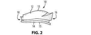
図2及び図3は、本発明の実施形態による人工椎間板10を示す。図示のように、椎間板10は上側シェル12及び下側シェル14を備え、前方端16及び後方端18を含む。シェル12及び14のそれぞれの外側上面13及び外側下面15には、隣の椎体骨構造間の空間への埋め込みを向上又は容易にするのに必要とし得るような所望の表面構造又は形状を与えてもよい。例えば、図示の実施形態では、上側シェルの外側上面13は凸状であってもよい。さらに、骨の内部成長を容易にする及び/若しくは引き起こすように、並びに/又は、隣接する骨構造への接着を他の方法で促進させるように、面13及び15には任意の既知の被覆又は表面処理を施してもよい。そのような被覆等は当業者に既知である。さらに、シェル12及び14の外面には、隣接する骨構造に椎間板10を固定するさらなる固定(anchoring:係留)用の機構を設けてもよい。そのような機構としては、隣接する椎体間での本発明の埋め込みを容易にするか又は向上させる、例えば、ねじ、スパイク、穴若しくはピン(図示せず)を挙げることができる。
2 and 3 show an
さらに、本発明の椎間板10は人工椎体に関連する使用に適合させることができる。そのような場合、本発明の椎間板10には、人工椎体に固定するために使用することができる例えばキール等の様々な係留手段(図示せず)を設けてもよい。そのような人工椎体の一例が、本出願人の同時係属中のWO2006/116850として公開されたPCT出願に挙げられており、その内容全体は参照により本明細書に援用される。概して、本発明の椎間板10には、2つの構造が組み合わせられる場合、人工椎体の隣接する表面への取付けを容易にするであろう任意の外面又は表面手段を設けてもよい。取付手段により、人工椎間板と人工椎体との間に或る程度の相対運動を可能にすることができる。したがって、(図2及び図3に示すような)一実施形態では、外側下面15には、自然な椎体に適合するように湾曲形状が与えられているが、この面には、人工椎体の表面と係合又は協働するように構成された異なる構造も設けることができる。人工椎間板及び人工椎体は双方とも、それらの間にそのような協働的構成を可能にするように設計することができる。
Furthermore, the
図3及び図5に示すように、本発明の椎間板10には好ましくは、上面(上方)又は下面(下方)から見た場合に、概ね長楕円形、長円形又は楕円形の形態が与えられている。椎間板のこの形状は、隣接する椎体との表面接触を最大にするという点に関して好ましいことが、当業者には理解されるであろう。しかしながら、様々な他の形状、サイズ及び割合も可能である。また、図示のように、椎間板10には好ましくは、上方及び下方で異なり得る特定の外側形状を与えてもよい。例えば、本明細書に添付されている図に示す外側の審美的特性により、隣接する椎骨構造の自然な形状を反映することによって既存の骨構造内への埋め込みを容易にしてもよい。しかしながら、本発明は、いずれの形状又はサイズにも限定されないことが分かるであろう。さらに、添付の図面に示す椎間板の外側形状は、人工椎体との使用に必要とされなくてもよく又はそのような使用に好適でなくてもよいことが分かるであろう。
As shown in FIGS. 3 and 5, the
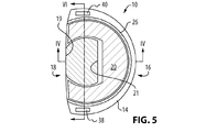
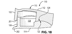
椎間板10を図4に矢状断面で示す。図示のように、上側シェル12及び下側シェル14は椎間板10を形成するように協働的に配置されている。シェル12とシェル14との間には弾性核20が設けられている。図4〜図6に示すように、下側シェル14の内面(すなわち上面)は、後方端18に近接する隆起した凸部分22を含む。以下にさらに説明するように、凸部分22は、上側シェル12の内面(すなわち下面)に設けた凹部分すなわち凹面24と協働してボールソケットジョイントを形成する。理解されるように、そのようなジョイントにより、シェル12及び14を関節運動式に協働させることで様々な方向への相対運動が可能になる。図4及び図5に示すように、一実施形態では、凸部分すなわちボール22は下側シェルの後方端18に配置することができる。ボール22の後方端19及び前方端21は好ましくは、先端が切り取られているか又は直角に切り落とされている。当業者に理解されるように、また、以下にさらに説明するように、凸部分22及び/又は凹部分24の形状、位置及び寸法は、所望の動きの範囲若しくは程度、又は回転軸に応じて調整することができる。
The
下側シェルはまた、上方に延びる外壁26も含むことで、凸部分すなわちボール22と外壁26との間の境界をなすウェル28が得られ、このウェル28内に核20が収容される。図5に示すように、図示の実施形態のウェル28は概して、後方に延びる「U」字形のようなアームを有する「U」字状構造を有する。核20には好ましくは、核がウェル28の形状に合致してその中に収容されるように同様の構造が与えられる。しかしながら、理解されるように、また、以下にさらに述べるように、ウェル28及び/又は核20には、同じ機能を達成する他の形状を与えることもできる。
The lower shell also includes an outwardly extending
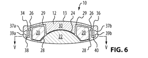
図4及び図6に示すように、上側シェル12には、下方に延びる後方部分30が設けられており、後方部分30の下面は上記の凹面24すなわちソケットを含む。上記に説明したように、上側シェル12の凹面すなわちソケット24は、下側シェルの凸部分すなわちボール22と協働してそれらの間に関節運動ジョイントを形成するように構成又は設計される。上側シェル12は、少なくともその前方端に沿って下方に延びるリム32も含む。リム32は、下側シェルの壁26の正面すなわち前方に位置するようにサイズ決めされる。以下にさらに説明するように、この構成は、屈曲及び伸展運動、すなわち、上側シェルが下側シェルに対して前方又は後方に動く運動に対して「急な停止」を与える役割を果たす。図4に示す椎間板は、上側シェル12を、そのリム32が下側シェルの壁26と接触することで上側シェル12のいずれのさらなる後方運動も防止する位置で示す。シェルのリム32及び壁26は連続している必要も、それぞれのシェルの外周全体に沿って延びている必要もないことが理解されるであろう。
As shown in FIGS. 4 and 6, the
図4及び図6に示すように、上側シェルは、後方のソケット部分24を囲むリセス29を含む。リセス29が下側セクションのウェル28と実質的に同じ形状であることで、リセスとウェル28が組み合わせられると核のためのエンクロージャーを形成する。
As shown in FIGS. 4 and 6, the upper shell includes a
図6に示すように、上側シェル12には好ましくは、その側方端に、一対の下方に延びるタブ34、36も設けてもよい。タブ34及び36はそれぞれスロット38及び40内に受け入れられるように構成され、それらのスロットは下側シェル14の側方端に設けられている。例えば本出願人の同時係属中のWO2006/116852として公開されたPCT出願に教示されているように、この種のタブ及びスロットの構成は、側方湾曲運動及び軸回転運動に対して「急な停止」を与える役割を果たす。
As shown in FIG. 6, the
より具体的には、側方運動の場合、図6に見られるように、スロット38及び40はタブ34及び36の長さよりも深く下側シェル14へ延びる。したがって、上側シェル及び下側シェル間の側方又は左右方向の運動により、タブのうち一方の終端がそれぞれのスロットの基部と接触することで、その方向へのさらなる運動がいずれも防止される。軸回転の場合、スロット38及び40は、タブ34及び36よりも広くサイズ決めされることで、上側シェル及び下側シェルが、それらの間に形成されるボール22及びソケット24のジョイントを通じて、タブ34及び36の側縁がスロット38及び40の側壁に接触するまで回転することが可能になる。そのようなタブ及びスロットに関するさらなる詳細は、本出願人の上記同時係属中の出願に提示されている。椎間板自体の卵形形状により、回転運動に対して任意の必要な「停止」を与えることで、タブ34、36及びスロット38、40の必要性を回避することができることが理解されるであろう。椎間板10は、回転運動に対して拘束されていなくてもよく、又は代替的に、いかなる回転運動も阻止するように設計されてもよいことも理解されるであろう。当業者に既知であるように、椎間板の許容可能な回転の程度は様々な要因に応じて決まる。
More specifically, in the case of lateral movement, the
図4及び図6に示すように、弾性核20は、上側シェル12と下側シェル14の相対運動に対して抵抗を与える役割を果たす。例えば、図4に示すように、核20はシェル12及び14の前方端同士を互いに離すように弾性付勢し、その場合、核の弾性により、椎間板の前方部分に加えられた圧縮力によってシェルの前方部分同士は互いに近寄ることになる。シェルのこの種の動きは、例えば屈曲運動時(すなわち、上側シェル12が下側シェル14に対して前方に動く場合)に生じる。
As shown in FIGS. 4 and 6, the
図6は、外側の角度をつけた端部が上側シェル12及び下側シェル14の主としてそれぞれの側方端に設けられた、任意選択的な構造を示す。図示のように、上側シェル12は下方の角度をつけた端部37a及び37bを対向する側方端に含み、下側シェル14は上方の角度をつけた端部39a及び39bを含む。端部37a及び37bは端部39a及び39bそれぞれに対して対向するようにして配置される。図示のように、端部37a、b及び39a、bの配置により、椎間板10が側方に(すなわち、冠状面に沿って)圧縮されるとペンチのような機能が得られる。この配置は、埋め込まれて正常な運動を受けた椎間板10の周りに形成され得るいかなる瘢痕組織もせん断する役割を果たす。
FIG. 6 shows an optional structure in which the outer angled ends are provided primarily at the respective lateral ends of the
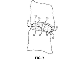
図7及び図8は本発明の屈曲運動を示す。図示のように、椎間板10は、損傷又は罹患した椎間板の切除後に創出された椎間腔内に埋め込まれた状態で示されている。椎間板10は図7には伸展位置、図8には屈曲位置で示す。見られるように、図7の伸展位置では、上側シェル12及び下側シェル14は図4において先に示した位置にあり、核20がウェル28及びリセス29によって形成されるエンクロージャー内に収容されている。しかしながら、屈曲運動の際に上側椎骨が前方に動くにつれ、上側シェル12のソケット30が下側シェル14のボール22の上を摺動可能に動く。図8に示すように、そのような屈曲運動の過程において、ソケット部分30の前方壁が弾性核20に衝突し、次に、弾性核20が下側シェル14の壁26に押し当たる。また、図示のように、屈曲運動の過程において、核20を収容するエンクロージャー29の体積が、上側シェル12のソケット30が下側シェルのボール22の上を摺動することにより減少する。図示のように、このようにして、上側シェルの前方端が垂直方向に下降することでエンクロージャー29の体積を収縮させる。理解されるように、そのような屈曲運動は、核がエンクロージャー内でそれ以上圧縮できなくなる(その時点でさらなる屈曲が防止される)まで持続することができる。核のそのような圧縮は、シェル間のそれぞれの動きに対する「緩やかな」停止機構としての役割を果たすことが理解されるであろう。
7 and 8 show the bending motion of the present invention. As shown, the
本発明の考えられ得る一実施形態では、椎間板10はまた、屈曲運動に対する「急な停止機構」として上述したタブ34、36及びスロット38、40を用いてもよい。すなわち、屈曲を制限するために、タブ及びスロットを、タブ34、36の前方縁がスロット38、40の前方壁と接触する(その時点でさらなる屈曲が防止される)まで或る特定の程度の運動だけを許容するようにサイズ決めしてもよい。
In one possible embodiment of the invention, the
上述の屈曲運動において、核20とリセス29の内壁との接触面が摩擦力を受ける場合がある。したがって、本発明は、そのような摩擦力を最小限にとどめることで核20への損傷を防止するように任意の既知の被覆又は処理等を施されるリセス29の壁を提供する。
In the bending motion described above, the contact surface between the
図8はまた、ボールすなわち凸部分22の曲率を示す。図示のように、ボール22は好ましくは、下の椎骨内の点Pからの半径「r」を有する球面を含む。図示のように、点「P」(椎間板10のための瞬間回転軸を規定する)は、下の椎骨の後方部分に位置付けされている。この位置付けは、後方に位置付けされる点、又はボール22及びソケット24によって形成される関節運動によるものである。
FIG. 8 also shows the curvature of the ball or
特定の場合では、人工椎間板の埋め込みは、特定の病態を緩和するために、隣接する椎骨の再整合を必要とする場合もある。例えば、椎骨は、脊柱前弯症を回復させるのに再整合が必要となる場合がある。理解されるように、本発明は必要に応じて、椎間板の瞬間回転軸を様々な所望の位置に位置付けすることを可能にする。回転軸の再位置付けは、例えば、本発明の椎間板10内に設けられるボール22の幾何学的形状及び位置を変えることによって達成することができる。すなわち、ボール22の形状を変えることによって、瞬間回転軸を前方又は後方に移動させることができる。したがって、例えば、図8の例示では、点Pは、ボール22及び関連するソケット24の位置を調整することによって前方方向又は後方方向に移動させることができる。さらに、ボール22の曲率も、位置と共に又は位置に関係なく調整することができることで、点Pの垂直方向の位置付けを変えることも可能であることも理解され得るだろう。例えば、上述の半径「r」を縮小することによって、瞬間回転軸(すなわち、図8に示す点「P」)を椎間板10の下側シェル14のより近くに位置するように垂直方向に上昇させることができることが理解されるであろう。そのような位置では、隣接する椎骨間の椎間関節に加えられるせん断応力を減らすことができる。
In certain cases, artificial disc implantation may require realignment of adjacent vertebrae to alleviate a particular condition. For example, the vertebrae may need to be realigned to restore lordosis. As will be appreciated, the present invention allows the instantaneous rotation axis of the intervertebral disc to be positioned at various desired positions as required. The repositioning of the rotational axis can be achieved, for example, by changing the geometry and position of the
さらなる実施形態では、凸部分22の曲率は様々な非球形形状を有していてもよい。例えば、前方端でより顕著になるように曲率を調整することによって、凸部分22が屈曲に対する動き抑制部として作用するように構成してもよい。凸部分、すなわち、ボール22に対するそのような調整は、所望のボール及びソケットの構成を依然として維持しつつ、1つ又は複数の動きに対して行うことができることが理解されるであろう。
In further embodiments, the curvature of the
上記に示したように、弾性核20は屈曲に対して漸増する抵抗を与える。そのような抵抗は核を含む材料の圧縮性に応じて決まるため、屈曲の程度はそのような材料の適当な特性を選択することによって調整することができることが理解されるであろう。例えば、圧縮性の低い材料製の核、又は、核を収容するエンクロージャーのより多くの体積を占める核は動きの範囲を低減するであろう。上述のように、核20が実質的に「U」字形のウェル28の形状とより容易に合致するように、核には好ましくは、実質的に「U」字形の構造が与えられる。しかしながら、理解されるように、ウェル28及び/又は核20には、同じ機能を達成する他の形状が与えられていてもよい。例えば、一実施形態では、核20はウェルの前方セクション内にだけ収容され、「U」字形アーム内には収容されないものとしてもよい。例えば、核は細長い(すなわち、長円形、卵形又は長楕円形)構造を有してもよい。そのような場合、ウェル28又はエンクロージャー29には、核の変位を防止する壁又は他のそのような障壁手段を設けてもよいことが理解されるであろう。別の実施形態では、核は、椎間板の前方部分にだけ位置する実質的に円形の構造を含んでもよい。そのような場合、核が与える「緩やかな」停止は屈曲運動の際にだけ有効であり得ることが理解されるであろう。上記では、核は単一体として言及されている。しかしながら、他の実施形態では、核を1つ又は複数の要素で設けてもよく、その理由は、上側シェルが組み合わせられると核の弾性により核がウェル(又はウェルの特定のセクション)の形状をとることができるためである。例えば、一実施形態では、核を、1つの前方セグメント及び2つの側方セグメントに相応する3つのセグメントで設けてもよい。さらに別の実施形態では、核を2つのセグメントで設けてもよく、セグメントはそれぞれ、椎間板のエンクロージャーの側方セクション(例えば、「U」字形ウェルの2つのアーム内)に位置する。そのような場合、核はもっぱら側屈運動に対する「緩やかな」停止機構として有効であり得ることが理解されるであろう。しかしながら、2つの核セグメントが椎間板の前方セクションに向かって伸びるのであれば、少なくとも或る程度の「緩やかな停止」が屈曲運動に対して与えられることが理解されるであろう。概して、本発明の核は好ましくは、屈曲及び側方圧縮運動に対して「緩やかな」停止を与える。したがって、これに基づき、また本開示を鑑み、核及び/又はウェルの形状及びサイズの他の様々な変更が当業者には明らかとなるであろう。
As indicated above, the
上記の説明は屈曲に焦点を置いているが、本発明の椎間板は他の様々な個々の運動又は複合運動も可能にする。例えば、上述したように、本発明は椎間板10に隣接した椎骨の制御された側方運動を可能にする。図6に示す実施形態では、実質的に「U」字形の構造を有する核20は、上側シェル12及び下側シェル14によって形成されたエンクロージャーの側方位置内に設けた「U」字形アームを含む。すなわち、実質的に「U」字形の核のアームはウェル28の側方部分を占める。この構成では、側方(すなわち、左右方向)運動時、椎間板の側方端の一方が圧縮を受けることが理解されるであろう。これは図19にも示す。この運動により、圧縮下の側に対応する核の側方部分の圧縮がもたらされる。屈曲及び伸展に関して上述したように、核の弾性は最大量の核圧縮が生じるまで側方圧縮量を徐々に制限する役割も果たす。したがって、これは、側方運動に対して「緩やかな」停止を与える。そのような運動は、核のための材料の適当な選択肢を選択することによって、及び/又は椎間板のエンクロージャー内に収容されている核の体積によって、上述のように制御することができる。上記に説明したように、上記の「U」字形構造を有する核が好ましいであろうが、本発明の人工椎間板には、任意の幾何学的形状の核を設けてもよい。例えば、核が長円形、卵形又は長楕円形の構造を含む場合では、少なくとも或る程度の側方圧縮が依然として生じることで、そのような核が側方運動に対して上記の「緩やかな」停止を与えることを可能にすることが理解されるであろう。代替的に、核は屈曲及び伸展運動に対してだけ「緩やかな」停止を与えるように設計してもよい。そのような選択肢は、本開示を再考すれば当業者には明らかであろう。
Although the above description focuses on flexion, the disc of the present invention also allows for various other individual or compound movements. For example, as described above, the present invention allows for controlled lateral movement of the vertebrae adjacent to the
別の態様では、椎間板10の様々な「急な停止」は、上記で説明したように、患者の必要性と、問題となっている椎骨の自然な動きの要求とに応じて、より広いか又はより狭い動きの範囲を与えるように調整することができる。
In another aspect, the various “rapid stops” of the
本発明の別の実施形態を図9〜図11に示し、これらの図では、同様の要素は上記と同じ参照符号で表されている。同様であるが変形形態を含む要素は、同じ参照符号で表されているが明確にするために文字「a」が付け加えられている。 Another embodiment of the present invention is shown in FIGS. 9-11, in which similar elements are denoted by the same reference numerals as above. Elements that are similar but include variations are denoted by the same reference numerals but with the letter “a” added for clarity.
図9〜図11に示すように、椎間板10aの全体的な構造は上述したものと同様である。さらに、上側シェル12は上記に説明した同じ構造を含む。しかしながら、下側シェル14は、瞬間回転軸を動的に変える手段を提供するように変更されている。より具体的には、図示の実施形態では、下側シェル14aの固定された凸部分、すなわち、ボール部分22の代わりに、凸上面を有する可動コア54が用いられている。図9〜図11に示すように、下側シェル14aにはリセス50が設けられており、リセス50は、一実施形態では、下側シェル14の後方端18に配置され、かつ、その側方端間の実質的に中央に配置されている。しかしながら、本開示に基づき、リセス50を必要に応じて任意の位置に配置することができることが理解されるであろう。リセス50は、実質的に平面的な基部52を含み、可動コア又は浮動コア54を受け入れるように構成される。コア54は、リセス50の基部52の上を摺動することが可能な実質的に平坦な下面56を有する。
As shown in FIGS. 9-11, the overall structure of the
図9〜図11に示すように、コア54は、上側シェル12の凹部分、すなわち、ソケット部分30と協働するように構成された凸上面58を含む。したがって、凸面58は上記に説明した凸面22と同じ機能を果たす。好適な実施形態では、コア54の凸上面、すなわち、ボール58は、埋め込まれると下方に隣接する椎体内に位置する、上記で説明した点「P」のような回転軸を有する球形形状を有する。さらに、上記で説明した実施形態の場合と同様に、コアの凸面58の幾何学的形状は、瞬間回転軸(すなわち、点「P」(図示せず))を任意の所望の位置に位置付けするように調整することができる。しかしながら、図9〜図11の実施形態は、コア54よりも大きい1つ又は複数の寸法を有するリセス50を設けることによって、そのような回転軸の位置付けのさらなる可変性を可能にする。例えば、一実施形態では、リセス50が矢状面で測定された場合にコアより大きいことでコア54を前後方向に摺動させてもよく、これにより、理解されるように、患者の正常な運動の過程において瞬間回転軸が並進する。そのような摺動運動の程度は、必要に応じてコア54とリセス50との間に小さな又は大きなクリアランスを設けることによって予め決定することができる。
As shown in FIGS. 9-11, the
図9〜図11に示す実施形態では、冠状面にわたるリセス50のサイズがコア54のサイズに非常に近いことで、前方−後方運動を依然として可能にしつつもコアのいかなる側方移動も防止する。しかしながら、別の実施形態では、下側シェル14aのリセス50は、コアのそのような側方運動も可能にするようにサイズ決めしてもよい。したがって、必要に応じてリセス50をサイズ決めすることによって、コア54に矢状面及び/又は冠状面における運動の自由度を与えることができる。
In the embodiment shown in FIGS. 9-11, the size of the
本発明の椎間板は、当業者に既知であるような種々の材料で作製することができる。例えば、シェルは金属(例えば、ステンレス鋼、チタン、チタン合金、ニチノール(商標)のようなニッケル−チタン合金、コバルト−クロム合金等)、陶材、並びにプラスチック及び/若しくは熱可塑性ポリマー(例えば、PEEK(商標))、又はそれらの任意の組合せから作製してもよい。さらに、下側シェルの「ボール」及び/又は上側シェルの「ソケット」は、それぞれのシェルの残りの部分と同じか又は異なる材料から作製してもよいことが理解されるであろう。例えば、「ソケット」及び双方のシェルはPEEKから作製するが、「ボール」はチタンから作製してもよい。材料の他の様々な組合せは当業者に既知である。 The intervertebral disc of the present invention can be made of a variety of materials as are known to those skilled in the art. For example, the shell may be metal (eg, stainless steel, titanium, titanium alloy, nickel-titanium alloy such as Nitinol ™, cobalt-chromium alloy, etc.), porcelain, and plastic and / or thermoplastic polymer (eg, PEEK). (Trademark)), or any combination thereof. Further, it will be appreciated that the lower shell “balls” and / or the upper shell “sockets” may be made of the same or different materials as the rest of the respective shells. For example, the “socket” and both shells are made from PEEK, while the “ball” may be made from titanium. Various other combinations of materials are known to those skilled in the art.
本発明の核20は概して弾性材料を含むものとして記載されている。一実施形態では、そのような材料は当該技術分野において既知の材料であるヒドロゲルを含む。しかしながら、代替的な材料を核に使用してもよい。例えば、核は、機械ばね(例えば、金属製)、油圧ピストン、ヒドロゲル若しくはシリコーンサック(silicone sac)、ゴム、ポリマー若しくはエラストマー材料、又は任意の他のそのような弾性材料又は素子を含んでいてもよい。核に適したポリマー材料の一例はカルボタン(carbothane(登録商標))であろう。概して、核は、上述したように、上側シェル12及び下側シェル14、14a間の運動を制限する役割を果たすと共に、椎間板10、10aをその中立位置に戻すために力を与える役割を果たす弾性圧縮可能な材料から作製される。
The
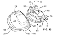
本発明の別の実施形態を図12〜図21に示し、これらの図では、上記要素と同様の要素は「1」を前に付して表されている。図示のように、図示の実施形態による椎間板110は上側シェル112及び下側シェル114を含む。人工椎間板110の外面には、必要とされ得る場合に任意の形状又は表面処理を施してもよい。例えば、上記で説明したように、上側シェル112の上面113には、埋め込まれた際に椎間板110が接触する椎体の形状に合致する形状が与えられていてもよい。
Another embodiment of the present invention is shown in FIGS. 12-21, in which elements similar to those described above are designated with a “1” in front. As shown, the
図13は椎間板110を開いた状態を示し、この図では、上側シェル112及び下側シェル114は分離している。図12及び図13の双方には、椎間板の核は示されていない。図12及び図13に見られるように、タブ134及び136が上側シェル112の両側面に設けられており、上記に説明したタブ構造と同様に機能する。先に説明した実施形態の場合と同様に、椎間板110の下側シェル114には一対のスロット138及び140が設けられており、スロットは1つずつ下側シェル114の各側面に設けられている。上記のように、スロット138及び140は、シェル112及び114が組み立てられて椎間板110を形成する際に、タブ134及び136をそれぞれ受け入れるように構成される。図12及び図13の実施形態では、スロット138及び140は、関連するタブ134及び136の幅よりも大きな幅を有するようにサイズ決めされていることが分かる。上記で説明したように、そのような構成は、関連するスロット138及び140内でのタブ134及び136の或る程度の並進運動を可能にする役割を果たす。スロット及びタブ間のそのような運動の自由度により、上側シェル112及び下側シェル114を互いに対して回転させることで、椎間板110が埋め込まれている脊椎分節の或る程度の軸回転運動が可能になる。回転運動の程度は、スロット又はタブのいずれかをサイズ決めすることによって調整してもよいことが理解されるであろう。椎間板の各側面にタブが1つだけ示されているが、同じ成果を達成するのに任意の数のタブを設けてもよいことが理解されるであろう。さらに、他の実施形態では、タブ及びスロットの位置は逆にしてもよく、その場合、タブが下側シェルに設けられ、スロットが上側シェルに設けられる。
FIG. 13 shows the
図13はまた、下側シェル114の外壁126によって画定された実質的に「U」字形のウェル128も示す。上記に説明したように、ウェル128は、椎間板110の核(図12及び図13には示さず)を収容する。図14は下側シェル114を示し、この図では、核120が図13に示すウェル128内に収容されている。
FIG. 13 also shows a substantially “U” shaped well 128 defined by the
図13及び図14に示す下側シェル114は、上述と同じようにして上側シェル112の凸面(図13及び図14には示さず)と協働する凸面すなわちボール122を有する。
The
先の幾つかの実施形態に関して記載したように、上側シェル112にはその前方端116にリム132が設けられている。リム132は、椎間板110が組み立てられて埋め込まれた状態にある場合は下側シェル114に向かう方向に延びている。一実施形態では、図12〜図14に示すように、下側シェルの下部分には、前方に延びていると共にリム132の下縁201の下に位置付けされるように構成されているリップ202が設けられてもよく、又は、下側シェルの下部分が、そのようなリップ202を形成するように延びていてもよい。以下にさらに記載するように、リップ202は、屈曲運動時に椎間板110に対するさらなる急な停止機構としての役割を果たす。
As described with respect to several previous embodiments, the
下側シェルのスロット138及び140はそれぞれ、前方壁203、205及び後方壁204、206によって画定される。上記で説明したように、スロット138及び140並びにタブ134及び136は、椎間板110が軸回転運動を受けるとタブがそれぞれのスロット内で移動することが可能となるようにそれぞれサイズ決めされる。そのような運動の際、タブのうち一方の前方縁がその関連するスロットの前方壁に当接すると同時に、タブのうち他方の後方縁がその関連するスロットの後方壁に当接することが理解されるであろう。椎間板110が反対方向に回転する場合、反対側の縁及び壁が当接することが理解されるであろう。
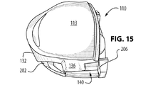
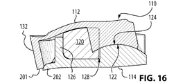
図15及び図16は、屈曲(すなわち、後方から前方への)運動時の椎間板110を示す。図示のように、また、上記で説明したように、そのような運動時、上側シェル及び下側シェルは、下側シェル114の凸面(すなわち、ボール)122と上側シェル112の凹面(すなわち、ソケット)124との間に形成されたボールソケット型の接続により関節運動する。そのような関節運動は、シェル112とシェル114との間で生じる全ての並進運動及び回転運動に対して生じることが理解されるであろう。図16に示すように、屈曲時、上側シェル112が下側シェル114に対して関節運動することで、ソケット部分124の本体と下側シェル114の外壁126との間で核120の圧縮が生じる。屈曲運動は、弾性核120がそれ以上圧縮できなくなるまで持続可能である。核120の圧縮は、そのような屈曲運動に対して、漸進的な、すなわち「緩やかな」停止機構としての役割を果たすことが理解されるであろう。しかしながら、「急な」停止を与えるために、図15及び図16に示す実施形態には他の特徴が設けられる。例えば、上記で説明したように、下側シェル114には、上側シェル112のリム132の下縁201のすぐ下で前方に延びるリップ202を設けてもよい。図15及び図16に示すように、そのような構成では、椎間板110の屈曲運動は下縁201がリップ202の上面と接触した時点で防止される。代替的に又は組み合わせて、スロット138及び140の前方壁203及び205はそれぞれ、屈曲運動に対する急な停止機構としての役割を果たすためにタブ134及び136の前方縁にそれぞれ当接するようにサイズ決めされてもよい。この特徴は図15に示され、この図では、椎間板10が完全な屈曲状態で示されており、タブ136の前方縁がスロット140の前方壁205に当接している(タブ134はスロット138の前方壁203に同様に当接していることが理解されるであろう)。
15 and 16 show the
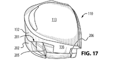
図17及び図18は、伸展(すなわち、前方から後方への)運動の際の実施形態の椎間板110を示す。図18では、明確にするために核120が省かれていることで、ウェル128が示されている。上記で説明したように、リム132の後方面が壁126の前方面と接触すると伸展運動に対して「急な」停止が生じる。図18に示すように、そのような接触は概して、壁126の上縁で生じる。しかしながら、この接触はリム132と壁126との間に設けたクリアランスの程度によることが理解されるであろう。すなわち、リム132と壁126との分離が図示の分離よりも小さい場合は、伸展時の2つの間の接触領域は下方に位置することになる。図17は、タブ134及び136並びにそれぞれのスロット138及び140が関わる伸展運動に対するさらなる急な停止を示す。すなわち、屈曲に関して上記で説明したように、伸展時に、タブ134及び136の後方縁がスロット138及び140の後方壁204及び206のそれぞれに向かって動く。したがって、理解されるように、そのような運動は、タブ134及び136の後方縁が後方壁204及び206と接触する(すなわち、「急な」停止に達する)と進行が防止される。
17 and 18 show the
図19は、上側シェル112及び下側シェル114間での側方(左右方向への)運動の際の実施形態の椎間板110(ただし、核120は有しない)を示す。図19に示すように、下側シェル114に対する上側シェル112の右から左への運動は、ボール122に対するソケット124の関節運動を伴う。そのような運動は、タブ136の下縁207がスロット140の基部208と接触する(この時点で、さらなる側方運動が防止される)まで持続する。また、図19では、下側シェル114に設けた壁126が上方に向かってテーパー状になっていることに留意されたい。理解されるように、右から左への運動時にタブ134を壁126との接触なく上昇させるにはこの構成が好ましい。上記の記載は右から左への運動に焦点を置いているが、左から右への側方運動時にも同様の停止に遭遇することが理解されるであろう。また、図19に示されるように、側方運動時に、椎間板の片側が圧縮され、その結果、ウェル128又はエンクロージャー内に存在し得る核(図示せず)の任意の部分が圧縮を受けることで、そのような運動に対して「緩やかな」停止が与えられる。
FIG. 19 shows the intervertebral disc 110 (but without the nucleus 120) during lateral (left-right) movement between the
椎間板110の上記記載は単一平面での特定の運動に関して述べてきたが、本発明により運動の様々な組合せが可能であることにも留意されたい。
It should also be noted that while the above description of the
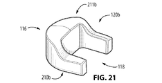
図20及び図21は、本発明の一実施形態による核の様々な代替実施形態を示す。明確にするために、これらの図の2つの実施形態をそれぞれ120a及び120bとして示す。図示の実施形態では、核120a及び120bは、椎間板(図示せず)の後方端118に向かって延びる「U」字形アームを有する実質的に「U」字形の構造を有するものとして示されている。核120a及び120bはそれぞれ下面210a、210b及び上面211a、211bを有する。図示のように、下面210a及び210bは実質的に平面であり、(上記で説明したように)椎間板の下側シェルのウェル内に収容されるように構成されている。図20及び図21に示す実施形態では、核120a、120bの前方(すなわち、116の方向)部分に肉厚セクションを設けていることで、核の上面211a、211bの前方端が後方端よりも隆起している。図20では、上面211aには傾斜形状がさらに与えられている。図20及び図21に示す核の構造により、より大きな分離力が核によって与えられて上側シェルが下側シェルから離隔されることが理解されるであろう。さらに、そのような分離力を椎間板の前方端116に集中させることによって、図20及び図21の核により、個人が直立している場合、椎間板を埋め込んでいる脊椎分節がその中立位置に移動する。すなわち、椎間板の前方端に加えられる分離力の増加により、(個人の頭の重量に対応するような)或る程度の圧縮が可能となるが、脊椎分節は依然として中立位置をとることになる。この特徴は主として、頚部の脊椎分節に埋め込まれている椎間板にとって、又は、上にかかる重量による核の圧縮を補償するように調節が望まれる場合には重要となり得ることが理解されるであろう。そのような調節が必要とされる特定の状況は当業者には明らかであろう。
20 and 21 illustrate various alternative embodiments of the nucleus according to one embodiment of the present invention. For clarity, the two embodiments of these figures are shown as 120a and 120b, respectively. In the illustrated embodiment, the
上記で説明した人工椎間板(例えば、10、10a等)は様々な特徴を含む。一態様では、椎間板は、軸回転、側屈及び屈曲/伸展等の個々の運動及び複合運動に適応する様々な構造的構成要素を含み得る。そのため、本発明の人工椎間板は、概して、自然な無傷の椎間板に関連する中立領域及び弾性領域の運動を再現する。さらに、本発明は、過度の又は非生理的な運動を防止する設計された終点手段によって、拘束されていない、及び/又は部分的に拘束されている複合運動を可能にする。完全に拘束された停止機構(すなわち、「急な停止機構」)により、運動が、例えば、弾性領域を超えて拡大しないことが確実になる。 The artificial discs described above (eg, 10, 10a, etc.) include various features. In one aspect, the intervertebral disc may include a variety of structural components that accommodate individual movements and compound movements such as axial rotation, lateral bending and flexion / extension. As such, the prosthetic disc of the present invention generally reproduces the neutral and elastic motion associated with a natural intact disc. Furthermore, the present invention allows unconstrained and / or partially constrained compound motion by designed end-point means that prevent excessive or non-physiological motion. A fully constrained stop mechanism (ie, a “rapid stop mechanism”) ensures that the motion does not extend beyond, for example, an elastic region.
別の態様では、椎間板は、前弯性の脊椎形態と一体化すると共にそれを促すように矢状面において実質的に楔形であってもよい。そのようなインプラントは、脊椎の再整合が求められる場合に使用することができる。例えば、椎間板は上記楔形を呈するように後方端の高さに比して前方端の高さが高くてもよい。同様に、そのような高さの差は椎間板の側面間、すなわち冠状面に与えられてもよい。この種の形態は、例えば、脊柱側弯症等の不整合を矯正するのに使用することができる。 In another aspect, the intervertebral disc may be substantially wedge-shaped in the sagittal plane so as to integrate with and promote the lordotic spine morphology. Such an implant can be used where spinal realignment is desired. For example, the intervertebral disc may have a height at the front end that is higher than the height at the rear end so as to exhibit the wedge shape. Similarly, such height differences may be imparted between the sides of the intervertebral disc, ie, the coronal plane. This type of form can be used, for example, to correct inconsistencies such as scoliosis.
別の態様では、椎間板のシェルのうち一方又は双方には、本発明の椎間板が冠状面に卵形又は半卵形の曲線を呈するように実質的に球形に湾曲した外面が与えられ得る。この構造は、椎間板を骨表面領域まで最大化することで骨の内部成長を促す。そのような構造はまた、埋め込み後に骨に対して椎間板を安定化しつつ、椎間腔でのプロテーゼの占領を最大化する。 In another aspect, one or both of the disc shells may be provided with a substantially spherically curved outer surface such that the disc of the present invention exhibits an oval or semi-oval curve in the coronal plane. This structure promotes bone ingrowth by maximizing the intervertebral disc to the bone surface area. Such a structure also maximizes the occupation of the prosthesis in the intervertebral space while stabilizing the disc against the bone after implantation.
様々な「急な停止機構」がシェル間の過度の側方運動、回転運動及び伸展運動を阻止するように設けられている。 Various “rapid stop mechanisms” are provided to prevent excessive lateral, rotational and extension movements between the shells.
上側シェル及び下側シェルの外面は、脊椎の任意の領域における両凹状又は矩形の椎間板切除部位に挿入するために湾曲又は球形(すなわち、卵形、楕円形)又は直線形(すなわち、四角形)であってもよい。外面には任意選択的に、隣接する骨構造又は他の人工脊椎構造に椎間板を固定する固定用のリブ又はキールを設けてもよい。 The outer surfaces of the upper and lower shells are curved or spherical (ie, oval, oval) or straight (ie, square) for insertion into a biconcave or rectangular discectomy site in any region of the spine There may be. The outer surface may optionally be provided with fixation ribs or keels that fix the intervertebral disc to adjacent bone structures or other artificial spinal structures.
一実施形態では、「正常な」状態により近似するように、矢状面(すなわち、前方−後方の方向)内での上側シェルの直径を下側シェルよりも大きくしてもよい。 In one embodiment, the diameter of the upper shell in the sagittal plane (i.e., the anterior-posterior direction) may be larger than the lower shell to more closely approximate the “normal” state.
一実施形態では、本発明の椎間板の外面に1つ又は複数の標識又は物理的な特徴を設けて、それをX線撮影時に不透明にすることができる。理解されるように、そのような特徴はインプラントの整合及び/又は位置付けを術後に確認するのに役立つ。 In one embodiment, one or more markers or physical features may be provided on the outer surface of the disc of the present invention to make it opaque during radiography. As will be appreciated, such features are useful for post-operative confirmation of implant alignment and / or positioning.
椎間板の設置面積(footprint)は、沈下をなくすのに役立つように冠状面及び矢状面の双方で最大化されることが好ましい。理解されるように、本発明の椎間板のサイズは、正常な脊椎内の椎間板の様々なサイズに適応するように変え得る。 The disc footprint is preferably maximized in both the coronal and sagittal planes to help eliminate subsidence. As will be appreciated, the size of the disc of the present invention can be varied to accommodate various sizes of discs within a normal spine.
上記で説明したように、上側シェル及び下側シェル間に形成されるボールソケット状ジョイントが、それらのシェル間の複雑な相対運動を可能にする。「ボール」部分には種々の幾何学的形状(例えば、曲率半径)を、必要に応じて異なる回転軸をもたらすように下側シェルに対して種々の位置に与えることができる。上述したボールソケットジョイント構成を提供するには上側シェルのソケット部分の同時位置付けもなされることが理解されるであろう。他の実施形態では、瞬間回転軸を動的に可変にさせると共に本発明の椎間板が与える動きの範囲においてより大きい可変性を可能にするように、拘束された空間内の1つ又は複数の平面内でボール部分を移動可能にしてもよい。 As explained above, the ball and socket joint formed between the upper shell and the lower shell allows complex relative movement between the shells. The “ball” portion can be provided with various geometric shapes (eg, radius of curvature) at various positions relative to the lower shell to provide different rotational axes as required. It will be appreciated that the socket portion of the upper shell may also be co-located to provide the ball and socket joint configuration described above. In other embodiments, one or more planes in the constrained space to make the instantaneous axis of rotation dynamically variable and allow greater variability in the range of motion provided by the disc of the present invention. The ball portion may be movable in the interior.
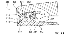
本発明の一実施形態では、椎間板の「ボール及びソケット」部分は、2つのシェル間に所望レベルの関節運動を可能にしつつ、それらのシェルの分離を防止するインターロック、すなわち雄型及び雌型構成を含んでいてもよい。この構成の一例は図22〜図24に示し、これらの図では、図4又は図16に示す椎間板の変形形態を示している。図22〜図24の実施形態に示すように、下側シェル314の後方端318に設けた「ボール」すなわち凸部分322は、シェル312及び314が組み合わせられている場合では上側シェル312に向かう方向に下側シェル314から離れて延びているステム400を含む。ステム400の対向端は凸上面404を有する第2の凸部分402を含む。一態様では、凸面404の曲率は凸部分322の曲率に対応し得る。しかしながら、以下の説明から理解されるように、本発明はそのような構成に限定されない。図24に示す実施形態では、凸部分402は概して、湾曲した円板状の要素を含む。図23は凸部分402を後方面図で示す。
In one embodiment of the present invention, the “ball and socket” portion of the intervertebral disc provides an interlock, ie male and female, that allows the desired level of articulation between the two shells while preventing separation of the shells. A configuration may be included. An example of this configuration is shown in FIGS. 22 to 24, and in these drawings, the deformed form of the intervertebral disc shown in FIG. 4 or FIG. 16 is shown. As shown in the embodiment of FIGS. 22-24, the “ball” or
図22〜図24に示すように、上側シェル312には、図4に示す面24と同様の凹面324が設けられている。凹面324はボール322の露呈面406と接触及び係合するように構成されている。ボール322の面406及び凹面324間の配置は、例えば図4の実施形態のボール22及び凹面24と同じであることが理解されるであろう。すなわち、そのような配置により、双方の要素のそれぞれの湾曲部分に対する関節運動が可能となる。しかしながら、図22及び図23に示すように、本発明の図示の実施形態は、さらなる対の関節運動面を有する上側シェル312を提供する。具体的には、上側シェル312には、凸部分402の凸面404と係合するように構成された第2の凹面408が設けられている。理解されるように、面408及び404が組み合わせられて、本発明の椎間板のための協働するさらなる対の関節運動面を提供する。
As shown in FIGS. 22 to 24, the
図22〜図24に示すように、凸部分402は好ましくはステム400よりも広い。図22〜図24に示す実施形態では、凸部分402は円板状であり、ステム400の直径又は幅よりも大きい直径を有する。また、上側シェル312には、下方に垂下する壁410と、好ましくは凸部分402の少なくとも一部を覆う、内方に延びる径方向フランジ412とが設けられている。図22及び図23に示すように、壁410及びフランジ412は凸部分402と確実に係合する役割を果たす。すなわち、図22及び図23に示すように、壁410及びフランジ412が組み合わせられて、ステム400に設けた凸部分402を係合させるためのソケット414を形成する。このようにして、ソケット414は、「雄型」凸部分402を受け入れるように構成された「雌型」部分を形成する。ステム400は「雄型」部分の一部とみなされてもよい。したがって、上側シェル312及び下側シェル314が組み合わせられると、凸部分402とソケット414との係合が、予め設定された限界を超えるシェルの分離を防止する役割を果たす。凸部分402をソケット414内に係合させるために、凸部分402が収容されるソケット414を形成するように、上側シェル312が先に2つのセクションで提供されて一緒に組み立てられるか又は連結される必要があるであろうことが理解されるであろう。同じ成果をもたらす様々な他の実施形態が可能であろう。例えば、フランジ412は、屈曲を可能にすることで、凸部分402がソケット414内に「スナップ嵌め」されることを可能にする弾性材料から作製してもよい。代替的に、ソケット414は、シェル312及び314が一緒に組み立てられて椎間板を形成することが可能になるのであれば、必ずしも凸部分402の外周全体と係合しなくてもよい。
As shown in FIGS. 22-24, the
図22及び図23に示すように、ソケット414は好ましくは、ソケット414及び凸部分402間の相対運動を可能にするようにサイズ決めされる。すなわち、ソケット414の直径は凸部分402の直径よりも大きい。理解されるように、この構成により、上側シェル312及び下側シェル314間で関節運動が可能となる。しかしながら、ソケット414を所望に応じてサイズ決めすることによって、そのような関節運動を1つ又は複数の方向に制限することができる。また、理解されるように、凸部分402の外縁が壁410と接触するとシェル間でそれぞれの運動が生じる。また、関節運動は一方向にだけ調整されてもよいことが理解されるであろう。例えば、ソケット414を実質的に長円形の形状を有して設計してもよく、それにより、一方向において別の方向よりも高い程度の相対運動が可能になる。そのような構成を用いて、例えば、側方運動とは対照的により大きな程度の屈曲及び伸展運動を可能にしてもよい。同様に、ソケット414のサイズ決めを調整して、より相対的な運動が、例えば屈曲運動とは対照的に伸展運動であることを可能にするようにしてもよく、その逆も可能である。また理解されるように、上記で説明した他の動き制限手段に加えて、ソケット414及び凸部分402の構成によって与えられる動き制限が概して存在する。
As shown in FIGS. 22 and 23, the
本発明の別の態様では、凸部分402の下面416には、この例では凹状である湾曲形状も設けてもよい。フランジ412の上面418にも、協働する凸形状を設けてもよい。図22及び図23に示すように、この構成により、面416及び418もまた互いに係合することで、上側シェル312及び下側シェル314の相対運動時に別の対の関節運動面を提供することが可能となる。したがって、一実施形態では、図22〜図24に示す椎間板には6つの対の関節運動面が設けられる。さらに、ソケット414及び凸部分402の構成により、シェル312及び314が確実に係合することで、その軸方向の分離が防止される。
In another aspect of the present invention, the
図22(他に以下でも説明する)では、面408及び404の曲率は実質的に同じ半径を有するものとして示されている。そのような構成は好ましいが限定的ではないことが理解されるであろう。さらに、面404、408の曲率は、面406及び324の曲率と同じであるものとして示されている。各対の面には異なる曲率半径が与えられてもよいことが理解されるであろう。しかしながら、上側シェル及び下側シェルの相対運動は概して枢動性を有するため、各対の当接面が共通の曲率半径を有することが好ましいであろう。
In FIG. 22 (also described below), the curvatures of
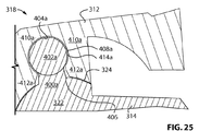
図25〜図27は、図22〜図24に関して説明したソケット414及び凸部分402の構成のさらなる実施形態を示す。図25〜図27では、図22〜図24に示す要素と同一の要素が同じ参照符号で表されている。同様であるが形状又は機能が異なる、図25〜図27に示すそれらの要素は、同じ参照符号で表されているが明確にするために文字「a」、「b」及び「c」がそれぞれ付け加えられている。
FIGS. 25-27 illustrate further embodiments of the
図25に示すように、凸部分402aは、凹面408a、壁410a及びフランジ412aの組合せによって形成されたソケット414a内に係合される「ボール」として示されている。先に記載した実施形態の場合のように、ソケット414aは、上側シェル312及び下側シェル314間の所要量の相対運動を可能にするように任意の所望の方法でサイズ決めされてもよい。
As shown in FIG. 25, the
図26は一実施形態を示し、この実施形態では、凸部分402bが図22〜図24に示す凸面と同様の凸面404bを有する。しかしながら、この例での凸部分402bは、形状が実質的に凹状である下面416bを有する。また、フランジ412bの上面418bは協働する凹形状を含む。
FIG. 26 shows an embodiment, in which the
図27はさらなる実施形態を示し、この実施形態は、図22及び図26に示す椎間板の組合せを含む。具体的には、図示のように、凸部分402cの上面404c及び上側シェルの凹下面408cは図22及び図23に示すものと実質的に同じである。しかしながら、凸部分402cの下面416cには凸部分と凹部分の組合せが設けられる。具体的には、図27に示す実施形態では、下面416cの後方部分318には凸形状が与えられ、下面416cの前方部分316には凹形状が与えられる。同様に、上面418cは後方端及び前方端がそのような異なる曲率に対応するように構成されている。理解されるように、必要性及び/又は所望の動きの要件及び制約に応じて、協働する面間の曲率の任意の他の組合せを用いてもよい。
FIG. 27 shows a further embodiment, which includes the combination of the intervertebral discs shown in FIGS. Specifically, as shown, the
上記では、図22〜図27に関して、様々な関節運動面は何らかの形態の曲線を有するものとして述べてきた。しかしながら、ここで提供したかかる図面及び他の図面、並びに本明細書における面の1つ又は複数は、平坦な又は波形の形状が与えられてもよいことが理解されるであろう。さらに、隣接する面には、それらの面間での相対運動を容易にするか又は限定するように任意の程度の相対的な摩擦が与えられてもよい。 In the above, with respect to FIGS. 22-27, the various articulating surfaces have been described as having some form of curve. It will be understood, however, that such and other figures provided herein, as well as one or more of the surfaces herein, may be provided with a flat or corrugated shape. In addition, adjacent surfaces may be provided with any degree of relative friction to facilitate or limit relative motion between the surfaces.
図28は、図22及び図23に示す実施形態の別の変形形態を示す。図22及び図23の要素と共通の、図28に示す要素は、同じ参照符号で表されている。同様であるが何らかの変形形態を含む要素は、共通の参照符号で示されているが明確にするために文字「e」が付け加えられている。図示のように、図28に示す構成は図23の構成と同様であるが、凸部分402e及びレール400eは2つのレール状構造を形成するように2つのセクションに分割されている。また、上側シェル312には、拡径基部422で終端する下方に延びるステム420を含む協働レールが設けられている。図28に示すように、ステム420と対応する基部422が組み合わせられて、一対の凸部分402eを受け入れるための一対のソケット又はリセス414eを形成する。図28は一対の凸部分402eを有して示されているが、椎間板は任意の数のそのような部分を有して設計されてもよいことが理解されるであろう。そのような場合、下方に延びるステム420及び関連する基部422の数も調整される。さらに、凸部分402eは凸下面を有して示されているが、上述したように、そのような面は凹状であってもよく、又はそれらの組合せであってもよいことが理解されるであろう。
FIG. 28 shows another variation of the embodiment shown in FIGS. Elements shown in FIG. 28 that are common to those in FIGS. 22 and 23 are denoted by the same reference numerals. Elements that are similar but include some variation are designated with a common reference number but have the letter “e” added for clarity. 28, the configuration shown in FIG. 28 is the same as the configuration of FIG. 23, but the
図29は図28の別の変形形態を示し、この図では、図28の要素と共通の要素は同じ参照符号で表されており、同様であるが何らかの変形形態を含む要素は、共通の参照符号で表されているが明確にするために文字「f」が付け加えられている。この場合では、凸部分402fは一対のものとして設けられていること、及びそのような部分はそれぞれのステム400fの外側側縁にわたってのみ延びていることに留意されたい。この実施形態はまた、外側にフレア状になった底部を有するのではなく実質的に一体型(monolithic)である、下方に延びるステム420fを示す。すなわち、図29では、図28のステム420と基部422は共に組み合わせられている。ステム420fの内面には、下側シェル314に設けた凸部分322の凸上面406との関節運動を可能にするように凹状曲線が与えられている。
FIG. 29 illustrates another variation of FIG. 28, in which elements common to those of FIG. 28 are designated with the same reference numerals, and elements that are similar but include some variation are common reference. Although represented by a symbol, the letter “f” is added for clarity. Note that in this case, the
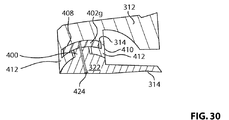
図30は、図22の実施形態のさらなる変形形態を示し、この図では、図28の要素と共通の要素は同じ参照符号で表されており、同様であるが何らかの変形形態を含む要素は、共通の参照符号で表されているが明確にするために文字「g」が付け加えられている。図30では、凸部分402gはステム400と一体形成されているのではなく該ステム400に固定されている。図示の実施形態では、そのような固定はスクリュー424によって達成される。図示のように、この固定を達成する手段は、下側シェル314の下面からねじを挿入してステム400に通すことを含む。理解されるように、この固定手段は好ましくは、椎間板を埋め込む前に行われる。任意のタイプの固定手段を用いて凸部分402gをステム400に固定することができることが理解されるであろう。
FIG. 30 shows a further variation of the embodiment of FIG. 22, in which elements that are common to the elements of FIG. 28 are denoted by the same reference numerals, and elements that are similar but include some variation are: Although represented by common reference signs, the letter “g” has been added for clarity. In FIG. 30, the
図31はさらに別の実施形態を示し、この実施形態では、上記に説明した凸部分が上側シェル312に固定されている。図31に示すように、下側シェル314は、先に述べたように、凸上面406を有する凸部分322を含み、上側シェル312は、前述の凸面406と係合するように構成された下側凹状関節運動面324を有する。しかしながら、図31の実施形態は、さらなる「ボール」部分が上記に示したような対向する向きとは対照的に上方から下方に延びているという点で図22の実施形態とは異なる。すなわち、上側シェルの後方ソケット部分318は、下端にフレア状部分432を有する下方に延びるステム430を有する。フレア状部分432は凹下面を有し、この凹下面は、下側シェル314のボール部分322の凸上面406と係合する凹面324を形成する。また、図31に示すように、下側シェルのボール部分322は、フレア状部分432を受け入れるように構成されたスロット436を有する。スロット436は凹面324、上方に延びる壁438、及び該壁438の上端に設けた内方に延びるフランジ440によって画定される。スロット436は、図22に関して上述したのと同じようにしてフレア状部分432を受け入れるように構成されている。同様に、フランジ440は、フレア状部分432の上面及び上側シェルの下部分によって画定されたそれぞれのリセス442内に受け入れられる。したがって、フレア状部分432がスロット436内に確実に受け入れられることとフランジ440がリセス442に受け入れられることの組合せが、シェル312及び314の分離を防止する役割を果たすと共に、それらのシェル間の任意の所望量の関節運動を可能にする。
FIG. 31 shows still another embodiment. In this embodiment, the convex portion described above is fixed to the
図22〜図31に関する上記の記載では、本発明の椎間板の他の様々な態様は、そのような要素が先に記載した要素と同じであるか又は同様であることから説明していない。例えば、図22〜図31に示す椎間板は好ましくは、先の実施形態に関して記載したような様々な力吸収及び動き制限手段を含む。そのような他の要素は単に説明を容易にするために図に示していないことが理解されるであろう。同様に、上述したように、本発明のシェルの外面又は骨係合面には、任意の様式の骨係合又は固定用の機構、被覆又は表面処理も施してもよい。例えば、外面には、当該技術分野において既知のような複数のスパイク又はキール等を設けてもよい。 In the above description with respect to FIGS. 22-31, various other aspects of the intervertebral disc of the present invention are not described because such elements are the same as or similar to those previously described. For example, the intervertebral discs shown in FIGS. 22-31 preferably include various force absorbing and motion limiting means as described with respect to previous embodiments. It will be understood that such other elements are not shown in the figures merely for ease of explanation. Similarly, as described above, the outer surface or bone engaging surface of the shell of the present invention may be subjected to any manner of bone engaging or securing mechanism, coating or surface treatment. For example, the outer surface may be provided with a plurality of spikes or keels as known in the art.
本発明を或る幾つかの特定の実施形態を参照しながら記載してきたが、本明細書に概説される本発明の目的及び範囲から逸脱しない限り、その様々な変更が当業者には明らかであろう。上記で引用した全参考文献の開示は全て、参照により本明細書に援用される。 Although the invention has been described with reference to certain specific embodiments, various modifications thereof will be apparent to those skilled in the art without departing from the scope and spirit of the invention as outlined herein. I will. The disclosures of all references cited above are hereby incorporated by reference.
Claims (9)
該椎間板が、
上側シェルと、下側シェルと、該上側シェル及び該下側シェルを離すように付勢する手段とを備え、
該上側シェル及び該下側シェルは、2つ以上の関節運動面により互いに対して可動であり、
該下側シェルは、後方に位置する凸部分を含む上面を有し、
該上側シェルは、該下側シェルの該上面に対向すると共に、該凸部分に対向する後方に位置する凹部分を含む下面を有し、
該凸部分及び該凹部分は、ボールソケットジョイントを形成するように関節運動式に協働し、
該凸部分又は該凹部分の少なくとも一方は、少なくとも1つの雄型部分を有し、該凸部分又は該凹部分の他方は、該少なくとも1つの雄型部分を受け入れると共に該雄型部分と確実に係合するように構成された対応する数の協働する雌型部分を有する、人工椎間板。 An artificial intervertebral disc implanted between adjacent upper and lower vertebrae of the spine,
The intervertebral disc
An upper shell, a lower shell, and means for biasing the upper shell and the lower shell apart,
The upper shell and the lower shell are movable relative to each other by two or more articulating surfaces;
The lower shell has an upper surface including a convex portion located at the rear,
The upper shell is opposed to the upper surface of the lower shell, and has a lower surface including a concave portion located in the rear facing the convex portion,
The convex portion and the concave portion cooperate in an articulated manner to form a ball and socket joint;
At least one of the convex portion or the concave portion has at least one male portion, and the other of the convex portion or the concave portion receives the at least one male portion and is securely connected to the male portion. An artificial disc having a corresponding number of cooperating female portions configured to engage.
Applications Claiming Priority (3)
| Application Number | Priority Date | Filing Date | Title |
|---|---|---|---|
| US12/274,685 US8057547B2 (en) | 2007-06-12 | 2008-11-20 | Articulating intervertebral disc prosthesis |
| US12/274,685 | 2008-11-20 | ||
| PCT/CA2009/001603 WO2010057293A1 (en) | 2008-11-20 | 2009-11-11 | Articulating intervertebral disc prosthesis |
Publications (1)
| Publication Number | Publication Date |
|---|---|
| JP2012509116A true JP2012509116A (en) | 2012-04-19 |
Family
ID=42198984
Family Applications (1)
| Application Number | Title | Priority Date | Filing Date |
|---|---|---|---|
| JP2011536710A Pending JP2012509116A (en) | 2008-11-20 | 2009-11-11 | Articulating disc prosthesis |
Country Status (11)
| Country | Link |
|---|---|
| US (1) | US8057547B2 (en) |
| EP (1) | EP2349116B1 (en) |
| JP (1) | JP2012509116A (en) |
| KR (1) | KR20110089289A (en) |
| CN (1) | CN102215787B (en) |
| AU (1) | AU2009317813A1 (en) |
| BR (1) | BRPI0922191A2 (en) |
| CA (1) | CA2743547A1 (en) |
| MX (1) | MX2011005308A (en) |
| RU (1) | RU2011123940A (en) |
| WO (1) | WO2010057293A1 (en) |
Families Citing this family (29)
| Publication number | Priority date | Publication date | Assignee | Title |
|---|---|---|---|---|
| EP1417000B1 (en) | 2001-07-11 | 2018-07-11 | Nuvasive, Inc. | System for determining nerve proximity during surgery |
| EP1435828A4 (en) | 2001-09-25 | 2009-11-11 | Nuvasive Inc | System and methods for performing surgical procedures and assessments |
| US7582058B1 (en) | 2002-06-26 | 2009-09-01 | Nuvasive, Inc. | Surgical access system and related methods |
| US8137284B2 (en) | 2002-10-08 | 2012-03-20 | Nuvasive, Inc. | Surgical access system and related methods |
| US7691057B2 (en) | 2003-01-16 | 2010-04-06 | Nuvasive, Inc. | Surgical access system and related methods |
| US7905840B2 (en) | 2003-10-17 | 2011-03-15 | Nuvasive, Inc. | Surgical access system and related methods |
| EP1680177B1 (en) | 2003-09-25 | 2017-04-12 | NuVasive, Inc. | Surgical access system |
| US8308812B2 (en) | 2006-11-07 | 2012-11-13 | Biomedflex, Llc | Prosthetic joint assembly and joint member therefor |
| US7914580B2 (en) | 2006-11-07 | 2011-03-29 | Biomedflex Llc | Prosthetic ball-and-socket joint |
| CA2668692C (en) | 2006-11-07 | 2013-06-18 | Biomedflex, Llc | Medical implants |
| US20110166671A1 (en) | 2006-11-07 | 2011-07-07 | Kellar Franz W | Prosthetic joint |
| US9005307B2 (en) | 2006-11-07 | 2015-04-14 | Biomedflex, Llc | Prosthetic ball-and-socket joint |
| US8512413B2 (en) | 2006-11-07 | 2013-08-20 | Biomedflex, Llc | Prosthetic knee joint |
| US7905919B2 (en) | 2006-11-07 | 2011-03-15 | Biomedflex Llc | Prosthetic joint |
| US8070823B2 (en) | 2006-11-07 | 2011-12-06 | Biomedflex Llc | Prosthetic ball-and-socket joint |
| US8029574B2 (en) | 2006-11-07 | 2011-10-04 | Biomedflex Llc | Prosthetic knee joint |
| US7976578B2 (en) * | 2008-06-04 | 2011-07-12 | James Marvel | Buffer for a human joint and method of arthroscopically inserting |
| US9066809B2 (en) * | 2009-05-15 | 2015-06-30 | Globus Medical Inc. | Method for inserting and positioning an artificial disc |
| US9265617B2 (en) * | 2010-10-06 | 2016-02-23 | Karin Buettner-Janz | Prosthesis for cervical and lumbar spine |
| US8496713B2 (en) | 2010-12-10 | 2013-07-30 | Globus Medical, Inc. | Spine stabilization device and methods |
| US9101485B2 (en) * | 2011-01-04 | 2015-08-11 | DePuy Synthes Products, Inc. | Intervertebral implant with multiple radii |
| WO2012103254A2 (en) * | 2011-01-25 | 2012-08-02 | Nuvasive, Inc. | Spinal implants for rotationally adjusting vertebrae |
| RU2550973C2 (en) | 2011-03-11 | 2015-05-20 | Фбс Девайс Апс | Vertebral implant, instrument for manufacturing and application method |
| US8480743B2 (en) * | 2011-03-25 | 2013-07-09 | Vicente Vanaclocha Vanaclocha | Universal disc prosthesis |
| US8790406B1 (en) | 2011-04-01 | 2014-07-29 | William D. Smith | Systems and methods for performing spine surgery |
| US8277505B1 (en) * | 2011-06-10 | 2012-10-02 | Doty Keith L | Devices for providing up to six-degrees of motion having kinematically-linked components and methods of use |
| RU2717924C2 (en) | 2014-11-24 | 2020-03-26 | Фбс Девайс Апс | Angulating bone plate |
| ES2875599T3 (en) * | 2016-03-30 | 2021-11-10 | Apifix Ltd | Adjustable spinal cage |
| US11350921B2 (en) * | 2018-03-31 | 2022-06-07 | The Research Foundation For The State University Of New York | Pressure-regulating implant and methods of use thereof |
Family Cites Families (27)
| Publication number | Priority date | Publication date | Assignee | Title |
|---|---|---|---|---|
| US5669936A (en) * | 1983-12-09 | 1997-09-23 | Endovascular Technologies, Inc. | Endovascular grafting system and method for use therewith |
| CA1283501C (en) * | 1987-02-12 | 1991-04-30 | Thomas P. Hedman | Artificial spinal disc |
| US5425773A (en) * | 1992-01-06 | 1995-06-20 | Danek Medical, Inc. | Intervertebral disk arthroplasty device |
| DE59206917D1 (en) * | 1992-04-21 | 1996-09-19 | Sulzer Medizinaltechnik Ag | Artificial intervertebral disc body |
| US5693079A (en) * | 1996-08-19 | 1997-12-02 | Augustine Medical, Inc. | Apparatus and method for simulating an inflatable thermal blanket to test an air source |
| US5782832A (en) * | 1996-10-01 | 1998-07-21 | Surgical Dynamics, Inc. | Spinal fusion implant and method of insertion thereof |
| US6146421A (en) | 1997-08-04 | 2000-11-14 | Gordon, Maya, Roberts And Thomas, Number 1, Llc | Multiple axis intervertebral prosthesis |
| US6679915B1 (en) * | 1998-04-23 | 2004-01-20 | Sdgi Holdings, Inc. | Articulating spinal implant |
| CA2329363C (en) * | 1998-04-23 | 2007-12-11 | Cauthen Research Group, Inc. | Articulating spinal implant |
| US6063121A (en) * | 1998-07-29 | 2000-05-16 | Xavier; Ravi | Vertebral body prosthesis |
| US20020035400A1 (en) * | 2000-08-08 | 2002-03-21 | Vincent Bryan | Implantable joint prosthesis |
| US6989032B2 (en) * | 2001-07-16 | 2006-01-24 | Spinecore, Inc. | Artificial intervertebral disc |
| US6572653B1 (en) * | 2001-12-07 | 2003-06-03 | Rush E. Simonson | Vertebral implant adapted for posterior insertion |
| DE60334897D1 (en) * | 2002-03-30 | 2010-12-23 | Infinity Orthopaedics Co Ltd | Medical Intervertebral Device |
| US6770095B2 (en) * | 2002-06-18 | 2004-08-03 | Depuy Acroned, Inc. | Intervertebral disc |
| US7156876B2 (en) * | 2002-10-09 | 2007-01-02 | Depuy Acromed, Inc. | Intervertebral motion disc having articulation and shock absorption |
| WO2005007040A1 (en) * | 2003-07-22 | 2005-01-27 | Synthes Gmbh | Intervertebral implant comprising dome-shaped joint surfaces |
| FR2864763B1 (en) * | 2004-01-07 | 2006-11-24 | Scient X | PROSTHETIC DISCALE FOR VERTEBRATES |
| US20050149196A1 (en) * | 2004-01-07 | 2005-07-07 | St. Francis Medical Technologies, Inc. | Artificial spinal disk replacement device with rotation limiter and lateral approach implantation method |
| US20050165407A1 (en) * | 2004-01-23 | 2005-07-28 | Diaz Robert L. | Disk arthroplasty instrumentation and implants |
| US7491239B2 (en) * | 2005-02-23 | 2009-02-17 | Joint Synergy, Llc | Interior insert ball and dual socket joint |
| US7806933B2 (en) * | 2004-03-15 | 2010-10-05 | Warsaw Orthopedic, Inc. | System and method for stabilizing a prosthetic device |
| ES2387392T3 (en) * | 2005-04-15 | 2012-09-21 | Eden Spine Europe Sa | Intervertebral disc prosthesis |
| KR20080021005A (en) * | 2005-05-02 | 2008-03-06 | 키네틱 스파인 테크놀로지스 인크. | Artificial intervertebral disc |
| WO2006116850A1 (en) | 2005-05-02 | 2006-11-09 | Kinetic Spine Technologies Inc. | Artificial vertebral body |
| EP1879528B1 (en) * | 2005-05-02 | 2012-06-06 | Kinetic Spine Technologies Inc. | Intervertebral disc prosthesis |
| US20080161932A1 (en) * | 2006-12-27 | 2008-07-03 | Kevin Armstrong | Artificial Disc |
-
2008
- 2008-11-20 US US12/274,685 patent/US8057547B2/en not_active Expired - Fee Related
-
2009
- 2009-11-11 MX MX2011005308A patent/MX2011005308A/en not_active Application Discontinuation
- 2009-11-11 CA CA2743547A patent/CA2743547A1/en not_active Abandoned
- 2009-11-11 KR KR1020117011712A patent/KR20110089289A/en not_active Application Discontinuation
- 2009-11-11 JP JP2011536710A patent/JP2012509116A/en active Pending
- 2009-11-11 RU RU2011123940/14A patent/RU2011123940A/en unknown
- 2009-11-11 EP EP09827073.9A patent/EP2349116B1/en not_active Not-in-force
- 2009-11-11 WO PCT/CA2009/001603 patent/WO2010057293A1/en active Application Filing
- 2009-11-11 CN CN200980145921.4A patent/CN102215787B/en not_active Expired - Fee Related
- 2009-11-11 AU AU2009317813A patent/AU2009317813A1/en not_active Abandoned
- 2009-11-11 BR BRPI0922191A patent/BRPI0922191A2/en not_active Application Discontinuation
Also Published As
| Publication number | Publication date |
|---|---|
| EP2349116A4 (en) | 2013-03-27 |
| AU2009317813A1 (en) | 2010-05-27 |
| US8057547B2 (en) | 2011-11-15 |
| EP2349116B1 (en) | 2019-01-09 |
| US20090138090A1 (en) | 2009-05-28 |
| CN102215787A (en) | 2011-10-12 |
| CA2743547A1 (en) | 2010-05-27 |
| CN102215787B (en) | 2015-11-25 |
| EP2349116A1 (en) | 2011-08-03 |
| KR20110089289A (en) | 2011-08-05 |
| RU2011123940A (en) | 2012-12-27 |
| WO2010057293A1 (en) | 2010-05-27 |
| BRPI0922191A2 (en) | 2015-12-29 |
| MX2011005308A (en) | 2011-07-29 |
Similar Documents
| Publication | Publication Date | Title |
|---|---|---|
| JP2012509116A (en) | Articulating disc prosthesis | |
| JP4639256B2 (en) | Artificial disc | |
| CA2702964C (en) | Hemi-prosthesis | |
| CN102014803B (en) | Artificial intervertebral spacer | |
| US20110054617A1 (en) | Intervertebral disc prosthesis having ball and ring structure | |
| US20060265072A1 (en) | Artificial intervertebral disc | |
| JP2011504377A (en) | Total posterior joint replacement | |
| KR101498657B1 (en) | Artificial intervertebral disc |