JP2012507675A - Bearing assembly and method for controlling fluid flow in a conduit - Google Patents
Bearing assembly and method for controlling fluid flow in a conduit Download PDFInfo
- Publication number
- JP2012507675A JP2012507675A JP2011534577A JP2011534577A JP2012507675A JP 2012507675 A JP2012507675 A JP 2012507675A JP 2011534577 A JP2011534577 A JP 2011534577A JP 2011534577 A JP2011534577 A JP 2011534577A JP 2012507675 A JP2012507675 A JP 2012507675A
- Authority
- JP
- Japan
- Prior art keywords
- bearing
- conduit
- assembly
- bearing assembly
- tapered roller
- Prior art date
- Legal status (The legal status is an assumption and is not a legal conclusion. Google has not performed a legal analysis and makes no representation as to the accuracy of the status listed.)
- Pending
Links
Images


Classifications
-
- F—MECHANICAL ENGINEERING; LIGHTING; HEATING; WEAPONS; BLASTING
- F16—ENGINEERING ELEMENTS AND UNITS; GENERAL MEASURES FOR PRODUCING AND MAINTAINING EFFECTIVE FUNCTIONING OF MACHINES OR INSTALLATIONS; THERMAL INSULATION IN GENERAL
- F16C—SHAFTS; FLEXIBLE SHAFTS; ELEMENTS OR CRANKSHAFT MECHANISMS; ROTARY BODIES OTHER THAN GEARING ELEMENTS; BEARINGS
- F16C33/00—Parts of bearings; Special methods for making bearings or parts thereof
- F16C33/30—Parts of ball or roller bearings
- F16C33/58—Raceways; Race rings
-
- F—MECHANICAL ENGINEERING; LIGHTING; HEATING; WEAPONS; BLASTING
- F16—ENGINEERING ELEMENTS AND UNITS; GENERAL MEASURES FOR PRODUCING AND MAINTAINING EFFECTIVE FUNCTIONING OF MACHINES OR INSTALLATIONS; THERMAL INSULATION IN GENERAL
- F16C—SHAFTS; FLEXIBLE SHAFTS; ELEMENTS OR CRANKSHAFT MECHANISMS; ROTARY BODIES OTHER THAN GEARING ELEMENTS; BEARINGS
- F16C19/00—Bearings with rolling contact, for exclusively rotary movement
- F16C19/22—Bearings with rolling contact, for exclusively rotary movement with bearing rollers essentially of the same size in one or more circular rows, e.g. needle bearings
- F16C19/34—Bearings with rolling contact, for exclusively rotary movement with bearing rollers essentially of the same size in one or more circular rows, e.g. needle bearings for both radial and axial load
- F16C19/36—Bearings with rolling contact, for exclusively rotary movement with bearing rollers essentially of the same size in one or more circular rows, e.g. needle bearings for both radial and axial load with a single row of rollers
- F16C19/364—Bearings with rolling contact, for exclusively rotary movement with bearing rollers essentially of the same size in one or more circular rows, e.g. needle bearings for both radial and axial load with a single row of rollers with tapered rollers, i.e. rollers having essentially the shape of a truncated cone
-
- F—MECHANICAL ENGINEERING; LIGHTING; HEATING; WEAPONS; BLASTING
- F16—ENGINEERING ELEMENTS AND UNITS; GENERAL MEASURES FOR PRODUCING AND MAINTAINING EFFECTIVE FUNCTIONING OF MACHINES OR INSTALLATIONS; THERMAL INSULATION IN GENERAL
- F16C—SHAFTS; FLEXIBLE SHAFTS; ELEMENTS OR CRANKSHAFT MECHANISMS; ROTARY BODIES OTHER THAN GEARING ELEMENTS; BEARINGS
- F16C33/00—Parts of bearings; Special methods for making bearings or parts thereof
- F16C33/30—Parts of ball or roller bearings
- F16C33/46—Cages for rollers or needles
- F16C33/4617—Massive or moulded cages having cage pockets surrounding the rollers, e.g. machined window cages
- F16C33/4623—Massive or moulded cages having cage pockets surrounding the rollers, e.g. machined window cages formed as one-piece cages, i.e. monoblock cages
- F16C33/4629—Massive or moulded cages having cage pockets surrounding the rollers, e.g. machined window cages formed as one-piece cages, i.e. monoblock cages made from metal, e.g. cast or machined window cages
-
- F—MECHANICAL ENGINEERING; LIGHTING; HEATING; WEAPONS; BLASTING
- F16—ENGINEERING ELEMENTS AND UNITS; GENERAL MEASURES FOR PRODUCING AND MAINTAINING EFFECTIVE FUNCTIONING OF MACHINES OR INSTALLATIONS; THERMAL INSULATION IN GENERAL
- F16K—VALVES; TAPS; COCKS; ACTUATING-FLOATS; DEVICES FOR VENTING OR AERATING
- F16K1/00—Lift valves or globe valves, i.e. cut-off apparatus with closure members having at least a component of their opening and closing motion perpendicular to the closing faces
- F16K1/16—Lift valves or globe valves, i.e. cut-off apparatus with closure members having at least a component of their opening and closing motion perpendicular to the closing faces with pivoted closure-members
- F16K1/18—Lift valves or globe valves, i.e. cut-off apparatus with closure members having at least a component of their opening and closing motion perpendicular to the closing faces with pivoted closure-members with pivoted discs or flaps
- F16K1/22—Lift valves or globe valves, i.e. cut-off apparatus with closure members having at least a component of their opening and closing motion perpendicular to the closing faces with pivoted closure-members with pivoted discs or flaps with axis of rotation crossing the valve member, e.g. butterfly valves
- F16K1/224—Details of bearings for the axis of rotation
-
- F—MECHANICAL ENGINEERING; LIGHTING; HEATING; WEAPONS; BLASTING
- F16—ENGINEERING ELEMENTS AND UNITS; GENERAL MEASURES FOR PRODUCING AND MAINTAINING EFFECTIVE FUNCTIONING OF MACHINES OR INSTALLATIONS; THERMAL INSULATION IN GENERAL
- F16C—SHAFTS; FLEXIBLE SHAFTS; ELEMENTS OR CRANKSHAFT MECHANISMS; ROTARY BODIES OTHER THAN GEARING ELEMENTS; BEARINGS
- F16C19/00—Bearings with rolling contact, for exclusively rotary movement
- F16C19/54—Systems consisting of a plurality of bearings with rolling friction
- F16C19/546—Systems with spaced apart rolling bearings including at least one angular contact bearing
- F16C19/547—Systems with spaced apart rolling bearings including at least one angular contact bearing with two angular contact rolling bearings
-
- F—MECHANICAL ENGINEERING; LIGHTING; HEATING; WEAPONS; BLASTING
- F16—ENGINEERING ELEMENTS AND UNITS; GENERAL MEASURES FOR PRODUCING AND MAINTAINING EFFECTIVE FUNCTIONING OF MACHINES OR INSTALLATIONS; THERMAL INSULATION IN GENERAL
- F16C—SHAFTS; FLEXIBLE SHAFTS; ELEMENTS OR CRANKSHAFT MECHANISMS; ROTARY BODIES OTHER THAN GEARING ELEMENTS; BEARINGS
- F16C2240/00—Specified values or numerical ranges of parameters; Relations between them
- F16C2240/40—Linear dimensions, e.g. length, radius, thickness, gap
-
- F—MECHANICAL ENGINEERING; LIGHTING; HEATING; WEAPONS; BLASTING
- F16—ENGINEERING ELEMENTS AND UNITS; GENERAL MEASURES FOR PRODUCING AND MAINTAINING EFFECTIVE FUNCTIONING OF MACHINES OR INSTALLATIONS; THERMAL INSULATION IN GENERAL
- F16C—SHAFTS; FLEXIBLE SHAFTS; ELEMENTS OR CRANKSHAFT MECHANISMS; ROTARY BODIES OTHER THAN GEARING ELEMENTS; BEARINGS
- F16C2361/00—Apparatus or articles in engineering in general
- F16C2361/91—Valves
-
- Y—GENERAL TAGGING OF NEW TECHNOLOGICAL DEVELOPMENTS; GENERAL TAGGING OF CROSS-SECTIONAL TECHNOLOGIES SPANNING OVER SEVERAL SECTIONS OF THE IPC; TECHNICAL SUBJECTS COVERED BY FORMER USPC CROSS-REFERENCE ART COLLECTIONS [XRACs] AND DIGESTS
- Y10—TECHNICAL SUBJECTS COVERED BY FORMER USPC
- Y10T—TECHNICAL SUBJECTS COVERED BY FORMER US CLASSIFICATION
- Y10T137/00—Fluid handling
- Y10T137/0318—Processes
-
- Y—GENERAL TAGGING OF NEW TECHNOLOGICAL DEVELOPMENTS; GENERAL TAGGING OF CROSS-SECTIONAL TECHNOLOGIES SPANNING OVER SEVERAL SECTIONS OF THE IPC; TECHNICAL SUBJECTS COVERED BY FORMER USPC CROSS-REFERENCE ART COLLECTIONS [XRACs] AND DIGESTS
- Y10—TECHNICAL SUBJECTS COVERED BY FORMER USPC
- Y10T—TECHNICAL SUBJECTS COVERED BY FORMER US CLASSIFICATION
- Y10T137/00—Fluid handling
- Y10T137/6851—With casing, support, protector or static constructional installations
- Y10T137/6855—Vehicle
- Y10T137/6906—Aerial or water-supported [e.g., airplane or ship, etc.]
Landscapes
- Engineering & Computer Science (AREA)
- General Engineering & Computer Science (AREA)
- Mechanical Engineering (AREA)
- Rolling Contact Bearings (AREA)
- Lift Valve (AREA)
Abstract
バルブ・システムが、貫通する流体の流れを有する導管と、バタフライ・バルブ・アセンブリとを含んでいる。バタフライ・バルブ・アセンブリは、導管内を斜めに延びるシャフトと、バタフライ・ディスクと、導管の外部表面上に位置する第1のベアリング・アセンブリと、を含む。バタフライ・ディスクは、シャフトを通して収容するサイズの通路を含む。バタフライ・ディスクは、バタフライ・バルブ・アセンブリが閉位置にあるときに、導管を通る流体流れを制限するように動作する。第1のベアリング・アセンブリが、シャフトの第1の端部を通して収容するように構成されている。第1のベアリング・アセンブリは、複数のテーパ・ローラ・ベアリングであって、ベアリング・レース内に周方向に離間に配置され、バタフライ・バルブ・アセンブリが閉位置にあるときにバタフライ・ディスクを実質的に一定の軸方向位置に保持するように構成されたテーパ・ローラ・ベアリングを含む。 The valve system includes a conduit having a fluid flow therethrough and a butterfly valve assembly. The butterfly valve assembly includes a shaft extending obliquely within the conduit, a butterfly disk, and a first bearing assembly located on the outer surface of the conduit. The butterfly disc includes a passage sized to be received through the shaft. The butterfly disk operates to restrict fluid flow through the conduit when the butterfly valve assembly is in the closed position. A first bearing assembly is configured to be received through the first end of the shaft. The first bearing assembly is a plurality of tapered roller bearings that are circumferentially spaced within the bearing race and substantially support the butterfly disc when the butterfly valve assembly is in the closed position. Includes a tapered roller bearing configured to be held in a fixed axial position.
Description
開示内容の分野は一般的に、バルブ・アセンブリに関し、より詳細には、バタフライ・バルブ・シャフト・ハウジング内で用いるテーパ・ローラ・ベアリングに関する。 The field of disclosure generally relates to valve assemblies and, more particularly, to tapered roller bearings for use in butterfly valve shaft housings.
バタフライ・バルブは、導管内の流体の流れを制御するために用いる多くのタイプのバルブの1つである。より具体的には、既知のバタフライ・バルブは、種々の量で貫通して流れる流体を制御する際に用いる流体流れ導管内で回転するディスク(「バタフライ」としても知られている)を含んでいる。このような既知のシステムでは、ディスクは、ディスクから半径方向外側に延びる2本のシャフトを含んでいる。2本のシャフトは、実質的に周方向に互いに対向して結合されている。各シャフトは、シャフト・ハウジング内に収容されていて、ディスクが、導管を横断する軸上で、開位置と閉位置の間で回転し得るようになっている。ディスクが開位置にあるときは、ディスクの平面は流れの方向と実質的に一致するかまたは平行であって、貫通する流体流量が最大になり得るようになっている。ディスクが閉位置にあるときは、ディスクの平面は流れの方向に対して実質的に横方向/直交であって、流体流量が最小限になるかまたは完全に遮蔽され得るようになっている。 A butterfly valve is one of many types of valves used to control the flow of fluid in a conduit. More specifically, known butterfly valves include a disk (also known as a “butterfly”) that rotates within a fluid flow conduit for use in controlling fluid flowing therethrough in various amounts. Yes. In such known systems, the disc includes two shafts extending radially outward from the disc. The two shafts are coupled to face each other substantially in the circumferential direction. Each shaft is housed in a shaft housing so that the disk can rotate between an open position and a closed position on an axis that traverses the conduit. When the disc is in the open position, the plane of the disc is substantially coincident with or parallel to the direction of flow so that the fluid flow rate therethrough can be maximized. When the disc is in the closed position, the plane of the disc is substantially transverse / orthogonal to the direction of flow so that fluid flow can be minimized or completely shielded.
既知のバタフライ・バルブ・アセンブリは、シャフト・ハウジング内に位置するベアリング・アセンブリであって、各シャフトを通して収容し、開位置と閉位置との間でディスクの実質的に滑らかな回転をもたらすベアリング・アセンブリを含んでいる。このようなアセンブリでは、ベアリング・アセンブリは、シャフトがハウジング内で回転するときに生じる摩擦の低減を容易にするベアリング・レース内に位置する複数の球状のベアリングを含んでいる。 A known butterfly valve assembly is a bearing assembly located within a shaft housing that receives through each shaft and provides a substantially smooth rotation of the disk between the open and closed positions. Includes assembly. In such an assembly, the bearing assembly includes a plurality of spherical bearings located within a bearing race that facilitates reducing friction that occurs when the shaft rotates within the housing.
既知のディスクの中には、代替的に、導管内に斜めに取り付けられて、一方のシャフト・ハウジングが他方の上流に位置し、ディスクの平面が流れの方向とある角度をなしてずれ得るようになっているものがある。閉位置に置かれて流れに遭遇したときに、ディスクは、背後に配置されたシャフトに沿って作用する軸力として解釈される負荷を受ける。しかし、このようなシステムにおけるディスクは、それと分かるどんな軸方向変位も受けてはならない。なぜならば、ディスクは、閉位置に戻るたびに、同じ位置に戻らなければならないからである。丸いローラ・ベアリングをベアリング・アセンブリ内で用いる既知のシステムは、ディスクの軸方向変位を受けるため、斜めに取り付けたバタフライ・バルブ・ディスクを用いるシステムに適した軸方向位置制御がない。 Some known discs are alternatively mounted at an angle in the conduit so that one shaft housing is located upstream of the other and the plane of the disc can be offset at an angle with the direction of flow. There is something that is. When placed in the closed position and encountering a flow, the disk is subjected to a load that is interpreted as an axial force acting along the shaft located behind it. However, the disk in such a system should not be subject to any appreciable axial displacement. This is because every time the disk returns to the closed position, it must return to the same position. Known systems that use round roller bearings in the bearing assembly are subject to axial displacement of the disk, so there is no axial position control that is suitable for systems that use obliquely mounted butterfly valve disks.
一態様においては、バルブ・システムが提供される。バルブ・システムは、貫通する流体の流れを有する導管と、バタフライ・バルブ・アセンブリとを含む。バタフライ・バルブ・アセンブリは、導管内を斜めに延びるシャフトと、バタフライ・ディスクと、導管の外部表面上に位置する第1のベアリング・アセンブリと、を含む。バタフライ・ディスクは、シャフトを通して収容するサイズの通路を含む。バタフライ・ディスクは、バタフライ・バルブ・アセンブリが閉位置にあるときに導管を通る流体流れを制限するように動作する。第1のベアリング・アセンブリは、シャフトの第1の端部を通して収容するように構成されている。第1のベアリング・アセンブリは、複数のテーパ・ローラ・ベアリングであって、ベアリング・レース内に周方向に離間に配置され、バタフライ・バルブ・アセンブリが閉位置にあるときにバタフライ・ディスクを実質的に一定の軸方向位置に保持するように構成されたテーパ・ローラ・ベアリングを含んでいる。 In one aspect, a valve system is provided. The valve system includes a conduit having a fluid flow therethrough and a butterfly valve assembly. The butterfly valve assembly includes a shaft extending obliquely within the conduit, a butterfly disk, and a first bearing assembly located on the outer surface of the conduit. The butterfly disc includes a passage sized to be received through the shaft. The butterfly disk operates to restrict fluid flow through the conduit when the butterfly valve assembly is in the closed position. The first bearing assembly is configured to be received through the first end of the shaft. The first bearing assembly is a plurality of tapered roller bearings that are circumferentially spaced within the bearing race and substantially support the butterfly disc when the butterfly valve assembly is in the closed position. And a tapered roller bearing configured to be held in a fixed axial position.
別の態様においては、ベアリング・アセンブリが提供される。ベアリング・アセンブリは、シャフトの第1の端部を通して収容するように構成されている。第1のベアリング・アセンブリは、複数のテーパ・ローラ・ベアリングであって、ベアリング・レース内に周方向に離間に配置され、バタフライ・バルブ・アセンブリが閉位置にあるときにバタフライ・バルブ・アセンブリを実質的に一定の軸方向位置に保持するように構成されたテーパ・ローラ・ベアリングを含んでいる。 In another aspect, a bearing assembly is provided. The bearing assembly is configured to be received through the first end of the shaft. The first bearing assembly is a plurality of tapered roller bearings that are circumferentially spaced within the bearing race so that the butterfly valve assembly is positioned when the butterfly valve assembly is in the closed position. It includes a tapered roller bearing configured to be held in a substantially constant axial position.
さらに別の態様においては、導管内の流体の流れを制御するための方法が提供される。本方法は、バタフライ・バルブ・アセンブリを導管内に、シャフトが導管内を斜めに延びるように配置することであって、バタフライ・バルブ・アセンブリは、開位置と閉位置との間で動作可能なバタフライ・ディスクを含む、配置することを含む。また本方法は、導管の外部表面上に位置する少なくとも1つのベアリング・アセンブリ内に周方向に離間に配置された複数のテーパ・ローラ・ベアリングを用いて、バタフライ・ディスクを実質的に一定の軸方向位置に保持することを含む。 In yet another aspect, a method for controlling fluid flow in a conduit is provided. The method includes positioning the butterfly valve assembly in a conduit such that the shaft extends diagonally in the conduit, the butterfly valve assembly being operable between an open position and a closed position. Including placing, including butterfly discs. The method also uses a plurality of circumferentially spaced tapered roller bearings in at least one bearing assembly located on the outer surface of the conduit to cause the butterfly disk to move to a substantially constant axis. Including holding in a directional position.
非限定で非網羅的な実施形態について、以下の図を参照して説明する。なお、特に指示のない限り、同様の参照数字は、種々の図の全体に渡って同様の部分を指す。 Non-limiting and non-exhaustive embodiments are described with reference to the following figures. Unless otherwise indicated, like reference numerals refer to like parts throughout the various figures.
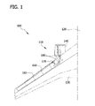
図1は、典型的な防氷装置110を含む典型的な航空機100の概略図である。典型的な実施形態においては、航空機100は、機体120と、そこから延びる翼130とを含み、また翼130に結合されたガス・タービン・エンジン140を含む。防氷装置110は、エンジン140から翼130の前縁160に沿って延びる導管150を含む。導管150のサイズおよび方向は、高温抽気170の流れをエンジン140から前縁160に沿って送って、寒い天候条件および/または飛行中に生じる翼130上への氷の蓄積を実質的に防止するように設定されている。防氷装置110は、エンジン140から前縁160に沿って生じる抽気170の流れを調整するバルブ・アセンブリ180を含んでいる。あるいは、バルブ・アセンブリ180は、任意の航空機システム内において航空機内の任意の導管に沿って、または圧力調整と貫通する流体の制御とが必要である任意の他の車両内に配置しても良い。
FIG. 1 is a schematic diagram of an
図2は、図1に示す防氷装置110ともに用いる典型的なバルブ・システム200の断面図である。典型的な実施形態においては、バルブ・システム200は導管202内に位置する。これについては、本明細書でより詳細に説明する。バルブ・システム200はバタフライ・ディスク204を含む。バタフライ・ディスク204は、導管202内に位置し、そのサイズは、図2に示すようにバタフライ・ディスク204が閉位置にあるときに、導管202を通る流体流れ(矢印206によって示す)を実質的に最小限にするように設定されている。シャフト208が、バタフライ・ディスク204内に画定された通路210を通って延びている。シャフト208のサイズおよび方向は、バタフライ・ディスク204を開位置と閉位置との間で回転させるように設定されている。より具体的には、典型的な実施形態において、シャフト208は、導管202内の第1の箇所214における孔212を通って長さL1だけ延び、同様に、導管202内の半径方向に反対側の第2の箇所218における孔216を通って長さL2だけ延びている。典型的な実施形態においては、第1のベアリング・アセンブリ220が、導管202の外部表面224上の対応するベアリング・カバー222内に位置している。第1のベアリング・アセンブリ220のサイズおよび方向は、シャフト208の第1の端部226および長さL1を内部に収容するように設定されている。同様に、第2のベアリング・アセンブリ230が、導管202の外部表面224上の対応するベアリング・カバー232に位置している。第2のベアリング・アセンブリ230のサイズおよび方向は、シャフト208の反対側の第2の端部234および長さL2を内部に収容するように設定されている。動作中、バタフライ・ディスク204が開位置と閉位置との間で回転するときに、ベアリング・アセンブリ220、230によって、バタフライ・ディスク204の実質的に無摩擦の回転が実現される。これについては、本明細書でより詳細に説明する。
FIG. 2 is a cross-sectional view of an
図2に例示するように、シャフト208は、導管202を中心軸240から測定した角度α1で通り抜けて延びている。典型的な実施形態においては、角度α1は約80°である。あるいは、角度α1は、約75°〜約85°の範囲の角度であっても良いし、バルブ・アセンブリ200が本明細書で説明したように機能可能になる任意の角度であっても良い。
As illustrated in FIG. 2, the
図3は、図2に示すバルブ・システム200とともに用いる典型的なベアリング・アセンブリ300(たとえば、第1のベアリング・アセンブリ220および/または第2のベアリング・アセンブリ230など)の斜視図であり、図4は、その断面図である。典型的な実施形態においては、ベアリング・アセンブリ300は、内部のベアリング・レース310と、ベアリング・レース310内に位置する複数のテーパ・ローラ・ベアリング320と、ベアリング・ケージ330とを含む。ベアリング・ケージ330は、複数のローラ・ベアリング320をそれぞれ、内部のベアリング・レース310の周りの周方向位置に収容して保持する。これについては、本明細書で説明する。ベアリング・アセンブリは、外部のベアリング・リング340を含む。外部のベアリング・リング340は、内部のベアリング・レース310、テーパ・ローラ・ベアリング320、およびケージ330を内部に収容する。これについては、本明細書でより詳細に説明する。
3 is a perspective view of an exemplary bearing assembly 300 (eg,
図5は、図3に示すベアリング・アセンブリ300とともに用いる典型的なベアリング・レース310の端面図であり、図6はその断面図である。典型的な実施形態においては、ベアリング・レース310は、実質的に円筒型の断面であり、開口部350を含んでいる。開口部350のサイズおよび方向は、図2に示すように、シャフト208を通して収容するように設定されている。典型的な実施形態においては、ベアリング・レース310は、第1の端部352において直径D1を含み、第2の端部354において直径D2を含んでいる。D2はD1よりも大きく、斜めに配向された表面356が第1の端部352と第2の端部354との間を延びるようになっている。傾斜面356は、回転358の軸から角度α2でずれている。典型的な実施形態においては、角度α2は約15°である。あるいは、ベアリング・レース310のサイズおよび方向は、ベアリング・アセンブリ300が本明細書で説明したように機能可能になるように設定されている。
5 is an end view of a
典型的な実施形態においては、ベアリング・レース310は、傾斜面356上を長さL3だけ延びる溝360を含んでいる。溝360のサイズおよび方向は、テーパ・ローラ・ベアリング320を溝360内に収容するように設定されている。これについては、本明細書でより詳細に説明し、たとえば図3に示している。ベアリング・レース310は、ベアリング・レースの第1の端部352に隣接して位置する第1のフランジ362を含む。第1のフランジ362は、テーパ・ローラ・ベアリング320を溝360内に保持するものである。同様に、ベアリング・レース310は、ベアリング・レースの第2の端部354に隣接して位置する第2のフランジ364を含む。第2のフランジ364は、テーパ・ローラ・ベアリング320を溝360内にさらに保持するものである。あるいは、ベアリング・レース310は、任意のへり、延長部分、または保持要素として、テーパ・ローラ・ベアリング320を溝360内に実質的に保持し、またベアリング・アセンブリ300が本明細書で説明したように機能可能になるものを含んでいても良い。
In the exemplary embodiment, bearing
図7は、図3に示すベアリング・アセンブリ300とともに用いる典型的なテーパ・ローラ・ベアリング320の端面図であり、図8は、その断面図である。典型的な実施形態においては、テーパ・ローラ・ベアリング320は、実質的に円錐状の断面である。より具体的には、テーパ・ローラ・ベアリング320は、直径D3を有する第1の端部370と、直径D4を有する第2の端部372とを含んでいる。典型的な実施形態においては、D4はD3よりも大きい。テーパ・ローラ・ベアリング320は、輪郭が実質的に滑らかな外面374であって、テーパ・ローラ・ベアリング320が図6に示すようなベアリング・レース溝360内に収まるように長さL4を含む外面374を含んでいる。
7 is an end view of a typical tapered
典型的な実施形態においては、テーパ・ローラ・ベアリング320は、熱処理した440Cステンレス鋼を旋削プロセスを用いて機械加工することによって製造される。あるいは、テーパ・ローラ・ベアリングを、約650°Fまでの温度で用いても良い任意の耐食材料から製造しても良い。
In an exemplary embodiment, tapered
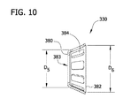
図9は、図3に示すベアリング・アセンブリ300とともに用いる典型的なベアリング・ケージ330の端面図であり、図10は、その断面図である。典型的な実施形態においては、ベアリング・ケージ330は実質的に円錐状の断面である。より具体的には、ベアリング・ケージ330は、直径D5を有する第1の端部380と、直径D6を有する第2の端部382とを含む。典型的な実施形態においては、D6はD5よりも大きい。典型的な実施形態においては、ベアリング・ケージ330は、開口部383を含んでいる。開口部383のサイズおよび方向は、ベアリング・レース310(図3に示す)を通して収容するように設定されている。典型的な実施形態においては、ベアリング・ケージ330は、複数の周方向に離間に配置された容器384を含んでいる。容器384のサイズおよび方向は、図3に示すように、対応する数のテーパ・ローラ・ベアリング320を内部に収容するように設定されている。またベアリング・ケージ330のサイズは、直径D5がベアリング・レースの直径D1よりも大きくなるように、またテーパ・ローラ・ベアリング320が溝360内に位置するときにベアリング・ケージ330がベアリング・レース310とテーパ・ローラ・ベアリング320とを内部に収容するように、設定されている。
9 is an end view of an
典型的な実施形態においては、ベアリング・ケージ330は、アルミニウム/青銅合金から加工プロセスを用いて製造される。あるいは、ベアリング・ケージを、約650°Fまでの温度で用いても良い任意の耐食材料から製造しても良い。
In the exemplary embodiment, the bearing
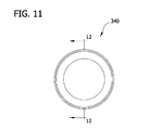
図11は、図3に示すベアリング・アセンブリ300とともに用いる典型的な外部のベアリング・リング340の端面図であり、図12は、その断面図である。典型的な実施形態においては、外部のベアリング・リング340は実質的に円形であり、そのサイズおよび構成は、ベアリング・レース310、テーパ・ローラ・ベアリング320、およびベアリング・ケージ330を内部に収容するように設定されている。より具体的には、典型的な実施形態において、外部のベアリング・リング340は内部の軌道面390を含んでいる。軌道面390のサイズおよび方向は、図3および4に示すように、テーパ・ローラ・ベアリング320が、対応する溝360および容器384内に位置したときに、テーパ・ローラ・ベアリング320を収容するように設定されている。内部の軌道面390は、角度α3として、テーパ・ローラ・ベアリング320が、対応する溝360および容器384内に位置したときにテーパ・ローラ・ベアリング320によって画定される角度α4(図4に示す)に実質的に等しい角度α3を含んでいる。
11 is an end view of a typical
図13は、導管(たとえば図1に示す導管150など)内の流体の流れを制御する方法400に対するフロー図である。典型的な実施形態においては、方法400は、本明細書で説明したように、シャフトが導管内を斜めに延びるように、バタフライ・バルブ・アセンブリを導管内に配置すること410を含む。バタフライ・バルブ・アセンブリは、開位置と閉位置との間で動作可能なバタフライ・ディスクを含む。バタフライ・バルブ・アセンブリを導管内に配置すること410はさらに、シャフトを導管内で流れの軸から約10度ずれた角度に配向すること420を含む。
FIG. 13 is a flow diagram for a
典型的な実施形態においては、方法400は、複数のテーパ・ローラ・ベアリングを加工プロセス(たとえば旋盤を用いた旋削プロセス、あるいは打ち抜きプロセスなど)を用いて製造すること430を含む。方法400は、バタフライ・ディスクを実質的に一定の軸方向位置に、導管の外部表面上に位置する少なくとも1つのベアリング・アセンブリ内の周方向に離間に配置された複数のテーパ・ローラ・ベアリングを用いて保持すること440を含む。バタフライ・ディスクを実質的に一定の軸方向位置に保持すること440はさらに、複数のテーパ・ローラ・ベアリングを約20度のベアリング角度に配向すること450を含む。
In an exemplary embodiment,
以上、ベアリング・アセンブリおよびバルブ・システムの典型的な実施形態について詳細に説明している。前述したベアリング・アセンブリによって、動作中のバルブ・システムの構成部品に対する軸方向および半径方向位置を保持することが、テーパ・ローラ・ベアリングをベアリング・レースおよびハウジング内に含むことによって容易になる。さらに、本明細書で説明したテーパ・ローラ・ベアリングは、焼き戻しされたステンレス鋼材料から製造される。焼き戻しされたステンレス鋼材料は、高温に耐え、また腐食を実質的に防止するため、本明細書で説明したテーパ・ローラ・ベアリングは、より広範囲の用途で用いても良い。 The foregoing has described in detail exemplary embodiments of the bearing assembly and valve system. The aforementioned bearing assembly facilitates maintaining axial and radial positions relative to the operating valve system components by including a tapered roller bearing within the bearing race and housing. Further, the tapered roller bearing described herein is manufactured from a tempered stainless steel material. Since the tempered stainless steel material withstands high temperatures and substantially prevents corrosion, the tapered roller bearing described herein may be used in a wider range of applications.
前述の説明には多くの詳細が含まれているが、これらは、本発明の範囲を限定するものと解釈してはならず、単に、現時点で好ましい実施形態のうちの一部についての説明を与えるものと解釈しなくてならない。同様に、本発明の趣旨または範囲から逸脱しない本発明の他の実施形態を考案しても良い。異なる実施形態から得られる特徴を組み合わせて用いても良い。したがって、本発明の範囲は、添付の請求項およびその合法的な均等物のみによって指示されて限定されるものであり、前述の説明によるものではない。本明細書で開示した本発明に対する付加、削除、および変更であって、請求項の意味および範囲に含まれるものはすべて包含される。 While the foregoing description includes numerous details, these should not be construed as limiting the scope of the invention, but merely a description of some of the presently preferred embodiments. It must be interpreted as giving. Similarly, other embodiments of the invention may be devised which do not depart from the spirit or scope of the invention. Features obtained from different embodiments may be used in combination. Accordingly, the scope of the present invention is intended to be limited only by the appended claims and their legal equivalents, and not by the foregoing description. All additions, deletions, and modifications to the invention disclosed herein are included within the meaning and scope of the claims.
本明細書で説明した装置および方法は、航空機上の防氷装置とともに用いるベアリング・アセンブリとの関連で説明しているが、当然のことながら、本装置および方法は航空宇宙用途に限定されない。同様に、例示したシステム構成要素は、本明細書で説明した特定の実施形態に限定されず、むしろシステム構成要素は、本明細書で説明した他の構成要素から独立および別個に用いることができる。 Although the devices and methods described herein are described in the context of a bearing assembly for use with an anti-icing device on an aircraft, it will be appreciated that the devices and methods are not limited to aerospace applications. Similarly, the illustrated system components are not limited to the specific embodiments described herein; rather, the system components can be used independently and separately from the other components described herein. .
本明細書で用いる場合、要素またはステップを単数形で記載して、その前に用語「a」または「an」がある場合には、複数の要素またはステップを排除していないものと理解しなくてはならない。ただし、このような排除が明確に記載されている場合は除く。さらに、本発明の「一実施形態」に言及する場合、記載された特徴をやはり取り入れているさらなる実施形態の存在を排除するものと解釈することは意図されていない。 As used herein, an element or step is described in the singular and is preceded by the term “a” or “an” and is not to be understood as excluding a plurality of elements or steps. must not. However, this excludes cases where such exclusion is clearly stated. Furthermore, references to “one embodiment” of the present invention are not intended to be interpreted as excluding the existence of additional embodiments that also incorporate the recited features.
この書面の説明では、実施例を用いて、本発明を、ベスト・モードも含めて開示するとともに、どんな当業者も本発明を実施できるように、たとえば任意の装置またはシステムを作りおよび用いること、ならびに取り入れた任意の方法を実行することができるようにしている。本発明の特許可能な範囲は、請求項によって定められるとともに、当業者に想起される他の実施例を含んでいても良い。このような他の実施例は、請求項の文字通りの言葉使いと違わない構造要素を有するか、または請求項の文字通りの言葉使いとの差が非実質的である均等な構造要素を含む場合には、請求項の範囲内であることが意図されている。 This written description uses examples to disclose the invention, including the best mode, and to enable any person skilled in the art to practice the invention, for example, to make and use any apparatus or system; As well as any method that has been adopted. The patentable scope of the invention is defined by the claims, and may include other examples that occur to those skilled in the art. Such other embodiments include structural elements that do not differ from the literal wording of the claim, or include equivalent structural elements that differ from the literal wording of the claim insubstantial. Are intended to be within the scope of the claims.
Claims (20)
バタフライ・バルブ・アセンブリと、を含み、
前記バタフライ・バルブ・アセンブリは、
導管内を斜めに延びるシャフトと、
前記シャフトを通して収容するサイズの通路を含むバタフライ・ディスクであって、前記バタフライ・バルブ・アセンブリが閉位置にあるときに、導管を通る流体流れを制限するように動作するバタフライ・ディスクと、
前記導管の外部表面上に位置し、前記シャフトの第1の端部を通して収容するように構成された第1のベアリング・アセンブリであって、ベアリング・レースに沿って周方向に離間に配置された複数のテーパ・ローラ・ベアリングを含み、前記バタフライ・バルブ・アセンブリが閉位置にあるときに、前記バタフライ・ディスクを実質的に一定の軸方向位置に保持するように構成された第1のベアリング・アセンブリと、を含むバルブ・システム。 A conduit containing a flow of fluid therethrough;
A butterfly valve assembly, and
The butterfly valve assembly is
A shaft extending diagonally within the conduit;
A butterfly disk including a passage sized to be received through the shaft, the butterfly disk operating to restrict fluid flow through the conduit when the butterfly valve assembly is in a closed position;
A first bearing assembly located on an outer surface of the conduit and configured to be received through a first end of the shaft, spaced circumferentially along the bearing race A first bearing comprising a plurality of tapered roller bearings configured to hold the butterfly disk in a substantially constant axial position when the butterfly valve assembly is in a closed position; And a valve system including the assembly.
前記第2のベアリング・アセンブリは第2のベアリング・ケージを含み、前記第2のベアリング・ケージは、前記第2の複数のテーパ・ローラ・ベアリングを内部に収容するように構成された第2の複数の容器を含む請求項2に記載のバルブ・システム。 The first bearing assembly includes a first bearing cage, the first bearing cage being configured to house the first plurality of tapered roller bearings therein. Including a plurality of containers,
The second bearing assembly includes a second bearing cage, and the second bearing cage is configured to receive the second plurality of tapered roller bearings therein. The valve system of claim 2, comprising a plurality of containers.
前記第2のベアリング・アセンブリは第2のベアリング・ケージを含み、前記第2のベアリング・ケージは、前記第2の複数のテーパ・ローラ・ベアリングを内部に収容するように構成された第2の複数の容器を含む請求項10に記載のベアリング・アセンブリ。 The first bearing assembly includes a first bearing cage, the first bearing cage being configured to house the first plurality of tapered roller bearings therein. Including a plurality of containers,
The second bearing assembly includes a second bearing cage, and the second bearing cage is configured to receive the second plurality of tapered roller bearings therein. The bearing assembly of claim 10 including a plurality of containers.
バタフライ・バルブ・アセンブリを導管内に、シャフトが導管内を斜めに延びるように配置することであって、バタフライ・バルブ・アセンブリは、開位置と閉位置との間で動作可能なバタフライ・ディスクを含む、配置することと、
導管の外部表面上に位置する少なくとも1つのベアリング・アセンブリ内に周方向に離間に配置された複数のテーパ・ローラ・ベアリングを用いて、バタフライ・ディスクを実質的に一定の軸方向位置に保持することと、を含む方法。 A method for controlling the flow of fluid in a conduit, comprising:
The butterfly valve assembly is positioned in the conduit such that the shaft extends diagonally in the conduit, the butterfly valve assembly having a butterfly disk operable between an open position and a closed position. Including, placing,
A plurality of tapered roller bearings circumferentially spaced within at least one bearing assembly located on the outer surface of the conduit is used to hold the butterfly disc in a substantially constant axial position. And a method comprising:
Applications Claiming Priority (3)
| Application Number | Priority Date | Filing Date | Title |
|---|---|---|---|
| US12/263,051 | 2008-10-31 | ||
| US12/263,051 US20100108932A1 (en) | 2008-10-31 | 2008-10-31 | Bearing assembly and a method for controlling fluid flow within a conduit |
| PCT/US2009/059304 WO2010062473A1 (en) | 2008-10-31 | 2009-10-02 | Bearing assembly and a method for controlling fluid flow within a conduit |
Publications (1)
| Publication Number | Publication Date |
|---|---|
| JP2012507675A true JP2012507675A (en) | 2012-03-29 |
Family
ID=41528587
Family Applications (1)
| Application Number | Title | Priority Date | Filing Date |
|---|---|---|---|
| JP2011534577A Pending JP2012507675A (en) | 2008-10-31 | 2009-10-02 | Bearing assembly and method for controlling fluid flow in a conduit |
Country Status (5)
| Country | Link |
|---|---|
| US (1) | US20100108932A1 (en) |
| EP (1) | EP2342486A1 (en) |
| JP (1) | JP2012507675A (en) |
| CA (1) | CA2741450A1 (en) |
| WO (1) | WO2010062473A1 (en) |
Families Citing this family (4)
| Publication number | Priority date | Publication date | Assignee | Title |
|---|---|---|---|---|
| US8662474B2 (en) * | 2011-02-04 | 2014-03-04 | Honeywell International Inc. | Combination bearings having improved load capacities and lifespan and valve assemblies including the same |
| US20140326913A1 (en) * | 2013-05-06 | 2014-11-06 | Michael Führer | Arrangement for operating a shut-off valve having a tapered plug |
| US11313473B2 (en) * | 2020-09-04 | 2022-04-26 | Hamilton Sundstrand Corporation | Butterfly valve with vibration resistant mount |
| CN114483694A (en) * | 2022-01-28 | 2022-05-13 | 徐州徐工矿业机械有限公司 | Integrated butterfly valve |
Citations (16)
| Publication number | Priority date | Publication date | Assignee | Title |
|---|---|---|---|---|
| JPS6026370U (en) * | 1983-07-29 | 1985-02-22 | 昭和飛行機工業株式会社 | butterfly valve |
| JPS6067299A (en) * | 1983-09-22 | 1985-04-17 | 新明和工業株式会社 | Icing preventive device for aircraft |
| JPS62129538A (en) * | 1985-11-29 | 1987-06-11 | Toyota Motor Corp | Supporting construction for throttle valve |
| JPH0437099U (en) * | 1990-07-26 | 1992-03-27 | ||
| JPH04110299A (en) * | 1989-12-29 | 1992-04-10 | Boeing Co:The | Deicing device for aircraft |
| JPH05141542A (en) * | 1991-11-18 | 1993-06-08 | Kubota Corp | Butterfly valve with metal valve seat |
| JPH11325261A (en) * | 1998-05-13 | 1999-11-26 | Kubota Corp | Position detector for inflated sheet |
| JP2000081152A (en) * | 1998-07-01 | 2000-03-21 | Masayasu Kamegawa | Inclination type butterfly valve |
| JP2004522923A (en) * | 2001-05-11 | 2004-07-29 | ザ ティムケン カンパニー | Low wear and low output bearings |
| JP2005133870A (en) * | 2003-10-31 | 2005-05-26 | Nsk Ltd | Tapered roller bearing for transmission |
| JP2005535850A (en) * | 2002-08-14 | 2005-11-24 | ノルド−マイクロ アクティエンゲゼルシャフト アンド カンパニー オーエッチジー | Butterfly valve for controlling gas pressure |
| JP2006090492A (en) * | 2004-09-27 | 2006-04-06 | Ntn Corp | Rolling component and antifriction bearing |
| JP2007246934A (en) * | 2006-03-13 | 2007-09-27 | Ntn Corp | Rolling member for rolling mill roll support and rolling bearing for rolling mill roll support |
| JP2007270874A (en) * | 2006-03-30 | 2007-10-18 | Jtekt Corp | Retainer for roller bearing, and conical bearing |
| JP2008121770A (en) * | 2006-11-10 | 2008-05-29 | Ntn Corp | Rolling bearing |
| JP2008223923A (en) * | 2007-03-14 | 2008-09-25 | Jtekt Corp | Rolling bearing |
Family Cites Families (24)
| Publication number | Priority date | Publication date | Assignee | Title |
|---|---|---|---|---|
| US3409269A (en) * | 1966-06-21 | 1968-11-05 | Pratt Co Henry | Pressure actuated resilient seals for valves |
| US3743450A (en) * | 1970-02-16 | 1973-07-03 | G Woodling | Directly mounted rotary valve on an axial thrust bearing load shaft |
| US4290615A (en) * | 1979-12-14 | 1981-09-22 | International Telephone And Telegraph Corporation | Butterfly valve |
| US4632360A (en) * | 1981-08-14 | 1986-12-30 | United Aircraft Products, Inc. | Butterfly type valve seal |
| US5370361A (en) * | 1994-04-25 | 1994-12-06 | The Boc Group, Inc. | Butterfly valve |
| US5531205A (en) * | 1995-03-31 | 1996-07-02 | Siemens Electric Limited | Rotary diesel electric EGR valve |
| JPH10196660A (en) * | 1996-11-13 | 1998-07-31 | Nippon Seiko Kk | Roller bearing |
| JP2000337391A (en) * | 1999-05-28 | 2000-12-05 | Minebea Co Ltd | Bearing device |
| JP4465895B2 (en) * | 2000-05-22 | 2010-05-26 | 日本精工株式会社 | Roller bearing |
| US6828041B2 (en) * | 2000-07-18 | 2004-12-07 | Nsk Ltd. | Rolling apparatus |
| CN100375853C (en) * | 2001-11-06 | 2008-03-19 | 日本精工株式会社 | Radial roller bearing |
| JP2005188738A (en) * | 2003-12-02 | 2005-07-14 | Ntn Corp | Tapered roller bearing |
| JP4385801B2 (en) * | 2004-03-15 | 2009-12-16 | 株式会社ジェイテクト | Tapered roller bearings |
| US7175350B2 (en) * | 2004-03-17 | 2007-02-13 | The Timken Company | Thermally compensated bearing system |
| JP2005273796A (en) * | 2004-03-25 | 2005-10-06 | Koyo Seiko Co Ltd | Bearing device for supporting pinion shaft |
| JP4800599B2 (en) * | 2004-07-05 | 2011-10-26 | Ntn株式会社 | Tapered roller bearing |
| DE102004046077A1 (en) * | 2004-09-23 | 2006-04-06 | Pierburg Gmbh | Exhaust flap means |
| US7571742B2 (en) * | 2005-03-23 | 2009-08-11 | Honeywell International Inc. | Butterfly outflow valve |
| DE102005022205A1 (en) * | 2005-05-13 | 2006-11-16 | Schaeffler Kg | Four row tapered roller bearing |
| JP4635838B2 (en) * | 2005-11-15 | 2011-02-23 | 株式会社ジェイテクト | Liquid lubricated tapered roller bearing device |
| US7984892B2 (en) * | 2006-02-21 | 2011-07-26 | Ge Aviation Systems, Llc | Low friction butterfly ring |
| EP1906037A3 (en) * | 2006-09-28 | 2010-03-17 | JTEKT Corporation | Tapered roller bearing |
| JP2008089039A (en) * | 2006-09-29 | 2008-04-17 | Jtekt Corp | Tapered roller bearing and differential device |
| EP1967749B1 (en) * | 2007-03-05 | 2018-10-31 | JTEKT Corporation | Tapered roller bearing with lubrication |
-
2008
- 2008-10-31 US US12/263,051 patent/US20100108932A1/en not_active Abandoned
-
2009
- 2009-10-02 EP EP09744510A patent/EP2342486A1/en not_active Withdrawn
- 2009-10-02 JP JP2011534577A patent/JP2012507675A/en active Pending
- 2009-10-02 CA CA2741450A patent/CA2741450A1/en not_active Abandoned
- 2009-10-02 WO PCT/US2009/059304 patent/WO2010062473A1/en active Application Filing
Patent Citations (16)
| Publication number | Priority date | Publication date | Assignee | Title |
|---|---|---|---|---|
| JPS6026370U (en) * | 1983-07-29 | 1985-02-22 | 昭和飛行機工業株式会社 | butterfly valve |
| JPS6067299A (en) * | 1983-09-22 | 1985-04-17 | 新明和工業株式会社 | Icing preventive device for aircraft |
| JPS62129538A (en) * | 1985-11-29 | 1987-06-11 | Toyota Motor Corp | Supporting construction for throttle valve |
| JPH04110299A (en) * | 1989-12-29 | 1992-04-10 | Boeing Co:The | Deicing device for aircraft |
| JPH0437099U (en) * | 1990-07-26 | 1992-03-27 | ||
| JPH05141542A (en) * | 1991-11-18 | 1993-06-08 | Kubota Corp | Butterfly valve with metal valve seat |
| JPH11325261A (en) * | 1998-05-13 | 1999-11-26 | Kubota Corp | Position detector for inflated sheet |
| JP2000081152A (en) * | 1998-07-01 | 2000-03-21 | Masayasu Kamegawa | Inclination type butterfly valve |
| JP2004522923A (en) * | 2001-05-11 | 2004-07-29 | ザ ティムケン カンパニー | Low wear and low output bearings |
| JP2005535850A (en) * | 2002-08-14 | 2005-11-24 | ノルド−マイクロ アクティエンゲゼルシャフト アンド カンパニー オーエッチジー | Butterfly valve for controlling gas pressure |
| JP2005133870A (en) * | 2003-10-31 | 2005-05-26 | Nsk Ltd | Tapered roller bearing for transmission |
| JP2006090492A (en) * | 2004-09-27 | 2006-04-06 | Ntn Corp | Rolling component and antifriction bearing |
| JP2007246934A (en) * | 2006-03-13 | 2007-09-27 | Ntn Corp | Rolling member for rolling mill roll support and rolling bearing for rolling mill roll support |
| JP2007270874A (en) * | 2006-03-30 | 2007-10-18 | Jtekt Corp | Retainer for roller bearing, and conical bearing |
| JP2008121770A (en) * | 2006-11-10 | 2008-05-29 | Ntn Corp | Rolling bearing |
| JP2008223923A (en) * | 2007-03-14 | 2008-09-25 | Jtekt Corp | Rolling bearing |
Also Published As
| Publication number | Publication date |
|---|---|
| CA2741450A1 (en) | 2010-06-03 |
| US20100108932A1 (en) | 2010-05-06 |
| WO2010062473A1 (en) | 2010-06-03 |
| EP2342486A1 (en) | 2011-07-13 |
Similar Documents
| Publication | Publication Date | Title |
|---|---|---|
| US9885369B2 (en) | Variable vane for gas turbine engine | |
| KR102556910B1 (en) | Vented bearing retainer for turbomachinery | |
| US8845271B2 (en) | Turbocharger bearing system | |
| US10364846B2 (en) | Seal runner | |
| US8328160B2 (en) | Seals, ball valve assemblies, and methods of operating ball valve assemblies | |
| CA2917362C (en) | Propeller blade mounting system | |
| EP3061942B1 (en) | Bearing assembly for a turbocharger, and a method for manufacturing a bearing assembly for a turbocharger | |
| EP3059453B1 (en) | Method of improving the efficiency of a turbocharger assembly comprising a ball bearing, associated product and turbocharger | |
| US20100278465A1 (en) | Compliant spherical bearing mount | |
| JP2012507675A (en) | Bearing assembly and method for controlling fluid flow in a conduit | |
| EP3252280B1 (en) | Circumferential plenum for oil damper | |
| US9816551B2 (en) | Turbocharger dual ball bearing system | |
| JP2009204004A (en) | Bearing device for turbocharger | |
| WO2009009645A2 (en) | Ground-based power generator with ball-roller bearing butterfly valve | |
| US9394939B2 (en) | Bearing system and methods of use thereof | |
| US7789567B2 (en) | Bearing with fluid flow bypass | |
| US9316148B1 (en) | Anti-rattle geometry for waste gate linkages using preloading technologies to reduce wear | |
| US20110155939A1 (en) | Butterfly valve assembly incorporating a unitary shaft and butterfly plate valve element | |
| JP2009203845A (en) | Bearing device for turbocharger | |
| WO2018090915A1 (en) | Thrust bearing | |
| BR112020025201B1 (en) | BEARING SET | |
| BR112020025201A2 (en) | BEARING ASSEMBLY, METHOD OF INSTALLING A SEALING WEAR BIPARTITE RING IN A BIPARTITE RACK FIXING A SET OF BIPARTITE BEARINGS AND CAGE ASSEMBLY FOR A CONICAL BIPARTITE BEARING |
Legal Events
| Date | Code | Title | Description |
|---|---|---|---|
| A621 | Written request for application examination |
Free format text: JAPANESE INTERMEDIATE CODE: A621 Effective date: 20120926 |
|
| A977 | Report on retrieval |
Free format text: JAPANESE INTERMEDIATE CODE: A971007 Effective date: 20131009 |
|
| A131 | Notification of reasons for refusal |
Free format text: JAPANESE INTERMEDIATE CODE: A131 Effective date: 20131022 |
|
| A02 | Decision of refusal |
Free format text: JAPANESE INTERMEDIATE CODE: A02 Effective date: 20140507 |