JP2012506336A - ADJUSTMENT DEVICE, ADJUSTMENT BODY, FAILURE RESISTANCE ADJUSTMENT SYSTEM, AND RECONFIGURATION METHOD FOR ADJUSTMENT SYSTEM - Google Patents
ADJUSTMENT DEVICE, ADJUSTMENT BODY, FAILURE RESISTANCE ADJUSTMENT SYSTEM, AND RECONFIGURATION METHOD FOR ADJUSTMENT SYSTEM Download PDFInfo
- Publication number
- JP2012506336A JP2012506336A JP2011532540A JP2011532540A JP2012506336A JP 2012506336 A JP2012506336 A JP 2012506336A JP 2011532540 A JP2011532540 A JP 2011532540A JP 2011532540 A JP2011532540 A JP 2011532540A JP 2012506336 A JP2012506336 A JP 2012506336A
- Authority
- JP
- Japan
- Prior art keywords
- load
- adjustment
- load sensor
- sensor
- function unit
- Prior art date
- Legal status (The legal status is an assumption and is not a legal conclusion. Google has not performed a legal analysis and makes no representation as to the accuracy of the status listed.)
- Pending
Links
- 238000000034 method Methods 0.000 title claims description 8
- 230000033001 locomotion Effects 0.000 claims abstract description 28
- 230000007246 mechanism Effects 0.000 claims description 31
- 230000005540 biological transmission Effects 0.000 claims description 20
- 238000012544 monitoring process Methods 0.000 claims description 20
- 230000008878 coupling Effects 0.000 claims description 13
- 238000010168 coupling process Methods 0.000 claims description 13
- 238000005859 coupling reaction Methods 0.000 claims description 13
- 230000008859 change Effects 0.000 claims description 4
- 238000005259 measurement Methods 0.000 claims description 3
- 238000012423 maintenance Methods 0.000 claims 1
- 230000004044 response Effects 0.000 description 6
- 230000004913 activation Effects 0.000 description 5
- 238000011156 evaluation Methods 0.000 description 4
- 230000001105 regulatory effect Effects 0.000 description 4
- 238000006243 chemical reaction Methods 0.000 description 3
- 230000009347 mechanical transmission Effects 0.000 description 3
- 238000010586 diagram Methods 0.000 description 2
- 230000000712 assembly Effects 0.000 description 1
- 238000000429 assembly Methods 0.000 description 1
- 230000015556 catabolic process Effects 0.000 description 1
- 230000006835 compression Effects 0.000 description 1
- 238000007906 compression Methods 0.000 description 1
- 238000006731 degradation reaction Methods 0.000 description 1
- 230000001419 dependent effect Effects 0.000 description 1
- 230000000694 effects Effects 0.000 description 1
- 230000005226 mechanical processes and functions Effects 0.000 description 1
- 230000004048 modification Effects 0.000 description 1
- 238000012986 modification Methods 0.000 description 1
- 238000012795 verification Methods 0.000 description 1
Images


Classifications
-
- B—PERFORMING OPERATIONS; TRANSPORTING
- B64—AIRCRAFT; AVIATION; COSMONAUTICS
- B64D—EQUIPMENT FOR FITTING IN OR TO AIRCRAFT; FLIGHT SUITS; PARACHUTES; ARRANGEMENT OR MOUNTING OF POWER PLANTS OR PROPULSION TRANSMISSIONS IN AIRCRAFT
- B64D45/00—Aircraft indicators or protectors not otherwise provided for
- B64D45/0005—Devices specially adapted to indicate the position of a movable element of the aircraft, e.g. landing gear
- B64D2045/001—Devices specially adapted to indicate the position of a movable element of the aircraft, e.g. landing gear for indicating symmetry of flaps deflection
Landscapes
- Engineering & Computer Science (AREA)
- Aviation & Aerospace Engineering (AREA)
- Fluid-Pressure Circuits (AREA)
- Transmission Devices (AREA)
- Retarders (AREA)
- Train Traffic Observation, Control, And Security (AREA)
- Safety Devices In Control Systems (AREA)
Abstract
航空機の調整フラップ(A1、A2;B1、B2)とコントローラ/モニタ(5)とに連結される調整装置(A11、A12、B11、B12、A21、A22、B21、B22)は、アクチュエータ(20)と、アクチュエータを調整フラップに連結する調整運動部(VK)と、ギアリング(25)とを有する。調整装置は、調整フラップの作動に起因してアクチュエータ(20)の入力部に生じる負荷を測定する第1負荷センサ(S1;S11−a、S12−a、S21−a、S22−a)と、アクチュエータ(20)の出力部(32)に生じる負荷を測定する第2負荷センサ(S2;S11−b、S12−b、S21−b、S22−b)とを備える。第1負荷センサ(S1)と第2負荷センサ(S2)は、調整装置に障害状態を割当てるために、負荷センサによって確認されたセンサ値を受信する調整装置障害識別機能部に連結されている。The adjusting devices (A11, A12, B11, B12, A21, A22, B21, B22) connected to the aircraft adjusting flaps (A1, A2; B1, B2) and the controller / monitor (5) are actuators (20). And an adjustment motion part (VK) for connecting the actuator to the adjustment flap, and a gear ring (25). The adjusting device includes a first load sensor (S1; S11-a, S12-a, S21-a, S22-a) that measures a load generated in the input portion of the actuator (20) due to the operation of the adjusting flap; A second load sensor (S2; S11-b, S12-b, S21-b, S22-b) that measures a load generated in the output section (32) of the actuator (20). The first load sensor (S1) and the second load sensor (S2) are connected to an adjustment device failure identification function unit that receives a sensor value confirmed by the load sensor in order to assign a failure state to the adjustment device.
Description
本発明は、航空機用の調整装置に関する。さらに本発明は、調整装置と調整装置障害識別システムとの結合体に関し、あるいは調整システムの再構成方法に関する。調整フラップは、一般に調整可能な航空機の空気力学フラップであり、とくに高揚力フラップとすることができる。とくに調整システムは、航空機の高揚力システムとすることができる。 The present invention relates to an adjustment device for an aircraft. Furthermore, the present invention relates to a combination of an adjustment device and an adjustment device fault identification system, or to a method for reconfiguring the adjustment system. The adjustment flaps are generally adjustable aircraft aerodynamic flaps, and can be particularly high lift flaps. In particular, the adjustment system can be an aircraft high lift system.
一般的な先行技術から知られているものは、とくに力同士の間の対立が生じるときに過剰負荷を回避するための負荷制限装置を有する高揚力システムである。 Known from the general prior art is a high lift system with a load limiting device to avoid overload, especially when conflicts between forces occur.
特許文献1は、アクチュエータの出力における負荷が測定される高揚力システムの駆動機構用の負荷センサについて記載している。
本発明の目的は、高揚力システムに生じる障害を、最小限の設備支出で局部にとどめ、それぞれ生じる障害を補償するために効率的システム低下を実行するのに使用される、航空機の調整フラップに連結される調整装置を提供することにある。さらに本発明の目的は、調整装置と調整装置障害識別機能部との結合体や、耐障害調整システムや、あるいは調整システムの再構成方法を提供することである。 It is an object of the present invention to provide aircraft adjustment flaps that are used to localize faults that occur in high lift systems with minimal equipment spending and to perform efficient system degradation to compensate for each fault that occurs. It is to provide an adjusting device to be coupled. It is a further object of the present invention to provide a combination of an adjustment device and an adjustment device failure identification function unit, a failure tolerance adjustment system, or a method for reconfiguring the adjustment system.
この目的は、独立請求項における特徴によって達成される。独立請求項を参照する従属請求項は、追加の実施形態について記載している。 This object is achieved by the features in the independent claims. The dependent claims, which refer to the independent claims, describe additional embodiments.
とくに本発明にかかる解決策は、調整装置における障害状態を予測するのに使用される。 In particular, the solution according to the invention is used to predict fault conditions in the regulating device.
本発明は、航空機の調整フラップに連結される調整装置または作動装置において、
・アクチュエータと;アクチュエータを調整フラップに運動学的に連結するサーボ運動部と;
・調整フラップの作動の結果としてアクチュエータの入力部において生じる負荷を検出するために、アクチュエータの入力部に配置された第1負荷センサと;
・調整フラップの作動の結果としてアクチュエータの出力部において生じる負荷を検出するために、アクチュエータの出力部に配置された第2負荷センサと
を備える調整装置または作動装置を提供する。
The present invention relates to an adjusting device or an operating device connected to an adjusting flap of an aircraft.
An actuator; a servo motion unit kinematically connecting the actuator to the adjustment flap;
A first load sensor arranged at the input of the actuator for detecting a load generated at the input of the actuator as a result of the operation of the adjustment flap;
An adjusting device or actuating device is provided comprising a second load sensor arranged at the output of the actuator for detecting a load generated at the output of the actuator as a result of the operation of the adjusting flap.
この場合において、第1負荷センサと第2負荷センサは、調整装置の機能的状態を監視するように、負荷センサによって取得されたセンサ値を送信するために調整装置障害識別機能部に機能的に連結されている。調整装置障害識別機能部は、負荷センサによって送信された信号に基づきフラップに配置されたサーボ装置に、障害状態を割当てることが可能なように設計されている。 In this case, the first load sensor and the second load sensor are functionally connected to the regulator fault identification function unit to transmit the sensor value obtained by the load sensor so as to monitor the functional state of the regulator. It is connected. The adjustment device failure identification function unit is designed so that a failure state can be assigned to the servo device arranged in the flap based on the signal transmitted by the load sensor.
2つ以上の調整装置がフラップ上に配置されたとき、本発明にかかる調整装置のうちの1つのみが2つの負荷センサを有して設計される、と提供される。少なくとも1つの追加の調整装置は、2つの負荷センサのうちの1つのみを有するかまたは負荷センサを有しないように設計される。 It is provided that when two or more adjusting devices are arranged on the flap, only one of the adjusting devices according to the invention is designed with two load sensors. The at least one additional regulator is designed to have only one of the two load sensors or no load sensor.
とくに本発明にかかる調整装置は、前縁フラップまたは後縁フラップの調整のために、高揚力システムのいくつかの調整装置のうちの1つとして使用される。調整運動部は、ここでは「トラック運動部」または「ドロップヒンジ運動部」として、とくに設計される。「トラック運動部」において、サーボ装置は、アクチュエータを介してレール(「トラック」)上を案内されるキャリッジとして設計される。サーボフラップは、駆動ロッドを介してキャリッジに連結され、好ましくは第1ヒンジは、駆動ロッドをキャリッジに連結し、第2ヒンジは、駆動ロッドをサーボフラップに連結する。いわゆる「ドロップヒンジ運動部」において、アクチュエータは、回転アクチュエータとして設計される。 In particular, the adjusting device according to the invention is used as one of several adjusting devices of a high lift system for adjusting the leading or trailing edge flaps. The adjusting motion part is specifically designed here as a “track motion part” or a “drop hinge motion part”. In the “track moving part”, the servo device is designed as a carriage guided on a rail (“track”) via an actuator. The servo flap is connected to the carriage via a drive rod, preferably the first hinge connects the drive rod to the carriage, and the second hinge connects the drive rod to the servo flap. In the so-called “drop hinge moving part”, the actuator is designed as a rotary actuator.
本発明の他の態様は、そのような調整装置と調整装置障害識別機能部との結合体を提供する。調整装置は、アクチュエータと、アクチュエータを調整フラップに運動学的に連結する起動運動部とを有する。オプションとして調整装置はまた、駆動機構によって発生された力を、アクチュエータに送信するギアリングを備えることもできる。調整装置は、調整装置を作動させるためにコントローラ/モニタに連結される。調整装置は、
・調整フラップの作動の結果としてアクチュエータの入力部において生じる負荷を検出するために、アクチュエータの入力部に配置された第1負荷センサと、
・調整フラップの作動の結果としてアクチュエータの出力部において生じる負荷を検出するために、アクチュエータの出力部に配置された第2負荷センサとを備える。
Another aspect of the present invention provides a combination of such an adjustment device and an adjustment device fault identification function. The adjustment device has an actuator and an activation movement that kinematically couples the actuator to the adjustment flap. Optionally, the adjustment device can also comprise a gear ring that transmits the force generated by the drive mechanism to the actuator. The adjustment device is coupled to the controller / monitor for operating the adjustment device. The adjustment device
A first load sensor disposed at the input of the actuator to detect a load generated at the input of the actuator as a result of the actuation of the adjustment flap;
A second load sensor arranged at the output of the actuator for detecting a load generated at the output of the actuator as a result of the operation of the adjustment flap;
第1負荷センサと第2負荷センサは、ここでは調整装置に障害状態を割当てるように、所定の基準がこれらのセンサ値の関数として満たされた場合に、負荷センサによって取得されたセンサ値を受信するために調整装置障害識別機能部に機能的に接続されている。調整装置障害識別機能部は、ここでは調整装置の機能的状態を監視することが可能なように設計されている。 The first load sensor and the second load sensor receive sensor values obtained by the load sensors when predetermined criteria are fulfilled as a function of these sensor values, here to assign fault conditions to the regulating device. In order to do so, it is functionally connected to the coordinator fault identification function unit. The adjusting device fault identification function unit is designed here so that the functional state of the adjusting device can be monitored.
調整装置障害識別機能部は、第1負荷センサと第2負荷センサとの各センサ値を少なくとも1つの制限値と比較し、第1負荷センサと第2負荷センサとの信号値がこの制限値を上回ったまたは下回ったか否かに基づき、調整装置の障害状態を決定するように構成される。 The adjustment device failure identification function unit compares each sensor value of the first load sensor and the second load sensor with at least one limit value, and the signal value of the first load sensor and the second load sensor determines the limit value. The controller is configured to determine a fault condition of the coordinator based on whether it is above or below.
とくに調整装置障害識別機能部は、第1負荷センサおよび第2負荷センサがそれぞれ無負荷制限未満の値を検出したとき、不機能状態(無負荷障害場面A)つまり障害状態を、各調整装置に割当てるように構成される。 In particular, the adjustment device failure identification function unit, when each of the first load sensor and the second load sensor detects a value less than the no-load limit, informs each adjustment device of a non-functional state (no-load failure scene A), that is, a failure state. Configured to allocate.
第1負荷センサが、第1負荷センサの位置における最大として定義される常時負荷の1/5未満の負荷を指し示し、かつ第2負荷センサが、第2負荷センサの位置における最大として定義されるかまたは通常動作中に実際に生じる常時負荷の1/5未満を指し示すセンサ信号を調整装置障害識別機能部に送信したとき、値が無負荷制限を下回ると、ここでは提供される。最大常時負荷は、翼または航空機のレイアウトに基づき規定される。したがって第1負荷センサが、第1負荷センサの位置における最大の所定または実際の常時負荷に対応する値の1/5未満として定義される負荷である無負荷制限未満のセンサ信号を、調整装置障害識別機能部に送信し、かつ第2負荷センサが、第1負荷センサの位置における最大の所定または実際の常時負荷に対応する値の1/5未満である無負荷制限未満のセンサ信号を、調整装置障害識別機能部に送信したとき、障害状態は調整装置に割当てら
れる。とくに値が無負荷制限を下回るのと同時に不機能状態は、航空機が整備中であるという条件を所定の適合性に割当てる、ということもここでは提供される。
Whether the first load sensor points to a load less than 1/5 of the full load defined as the maximum at the position of the first load sensor and the second load sensor is defined as the maximum at the position of the second load sensor Alternatively, when a sensor signal indicating less than 1/5 of the actual load that actually occurs during normal operation is sent to the regulator fault identification function, it is provided here if the value falls below the no-load limit. The maximum permanent load is defined based on the wing or aircraft layout. Therefore, the sensor signal below the no-load limit, which is a load defined by the first load sensor as less than 1/5 of the value corresponding to the maximum predetermined or actual constant load at the position of the first load sensor, is regulated. A sensor signal that is transmitted to the identification function and the second load sensor is below the no-load limit that is less than 1/5 of the value corresponding to the maximum predetermined or actual constant load at the position of the first load sensor. When transmitted to the device failure identification function unit, the failure state is assigned to the adjusting device. It is also provided here that, in particular, the non-functional state at the same time that the value falls below the no-load limit, assigns the condition that the aircraft is in service to a predetermined suitability.
とくにここでは過負荷障害場面Bとも称される他の場面において、第2負荷センサが、第2負荷センサの位置における常時負荷に対応する所定の制限値を上回る負荷L2に対応する信号値を生成し、そして調整装置障害識別機能部に送信する場合、および第1負荷センサによって測定された負荷L1が、第2負荷センサによって測定された負荷L2のものに対応する各調整運動部の入力部の動作範囲に存在する場合に、調整装置障害識別機能部は、故障の場合に調整装置の出力部に障害状態を割当てるように構成される。 In particular, another scene, also referred to as overload disorders scene B in this case, the second load sensor, a signal value corresponding to the load L 2 above the predetermined limit value corresponding to the constant load in the position of the second load sensor when generated, and for transmitting to the adjustment device failure identification module, and the load L 1 measured by the first load sensor, for each adjustment movement unit corresponds to that of the load L 2 measured by the second load sensor When present in the operating range of the input unit, the coordinator fault identification function unit is configured to assign a fault state to the output unit of the coordinator in the event of a failure.
とくに第2負荷センサの位置における常時負荷についての所定の制限値が、出力部についての所定のまたは測定された最大負荷Lmaxである、とここでは提供される。 In particular, it is provided here that the predetermined limit value for the constant load at the position of the second load sensor is the predetermined or measured maximum load L max for the output.
とくに以下ではギア障害場面Cと称される他の場面において、第1負荷センサによって生成された入力部の負荷L1についての信号値が、調整装置障害識別機能部が第2負荷センサによって測定された負荷L2から名目上確認する各調整運動部の入力部の動作範囲についての値を上回った場合、調整装置障害識別機能部は、アクチュエータまたは機械的伝達鎖に関する第1負荷センサと第2負荷センサとの間に存在する伝達部分の故障が生じていると各調整装置に、障害状態を割当てるように構成される。 Especially in other situations called gear failure scene C in the following, the signal value of the load L 1 of the input generated by the first load sensor, the adjusting device failure identification module is measured by the second load sensor when above the value of the operation range of the input portion of the adjusting movement unit for confirming nominally from the load L 2 has, adjusting device failure identification function section, the first load sensor and a second load relates to an actuator or mechanical transport chain When a failure occurs in a transmission portion existing between the sensors, each adjustment device is configured to be assigned a failure state.
とくに第1負荷センサによって測定された負荷L1が、アクチュエータのギア比を考慮に入れた、第2負荷センサによって測定された負荷L2の2倍を上回る、とここでは提供される。 In particular the load L 1 measured by the first load sensor, the gear ratio of the actuator taking into account, more than twice the load L 2 measured by the second load sensor, here to be provided.
とくに伝達障害場面Dにおいて、第1負荷センサによって確認された負荷が、所定の制限値を上回り、かつ第2負荷センサによって確認された負荷が、所定の制限値を下回ったことを、調整装置障害識別機能部が測定した場合、または第2負荷センサによって確認された負荷L2に対する第1負荷センサによって確認された負荷L1の比L1/L2が、所定の制限値を上回った場合に、調整装置障害識別機能部は、制限された性能能力の状態に基づきアクチュエータまたは第1負荷センサと第2負荷センサとの間に存在する伝達部分に、障害状態を割当てるように構成される。 In particular, in transmission failure scene D, the load confirmed by the first load sensor exceeds a predetermined limit value, and the load confirmed by the second load sensor falls below the predetermined limit value. When the identification function unit measures, or when the ratio L 1 / L 2 of the load L 1 confirmed by the first load sensor to the load L 2 confirmed by the second load sensor exceeds a predetermined limit value The coordinator fault identification function is configured to assign a fault condition to the actuator or a transmission portion that exists between the first load sensor and the second load sensor based on the state of the limited performance capability.
典型的な実施形態において、位置センサは、一般に調整フラップの位置を取得するように調整運動部に配置される。 In an exemplary embodiment, the position sensor is generally placed in the adjustment movement so as to obtain the position of the adjustment flap.
本発明の他の態様はまた、耐障害調整システムを提供する。耐障害調整システムは、航空機の各翼のうちの一つにおいて調整される少なくとも1つのフラップと、コントローラ/モニタによって作動される調整装置を有するコントローラ/モニタとを有し、調整装置の少なくとも1つは、各フラップに配置されている。 Another aspect of the invention also provides a fault tolerance adjustment system. The fault tolerant adjustment system has at least one flap that is adjusted on one of the wings of the aircraft and a controller / monitor having an adjustment device that is actuated by the controller / monitor, wherein at least one of the adjustment devices. Is located on each flap.
少なくとも1つまたは2つの調整装置は、フラップの翼長方向に互いに離隔されるように翼の各フラップ上に配置され、かつ駆動接続部に連結される。調整フラップにそれぞれ連結された1つ以上の調整装置は、それぞれ別個の駆動機構に連結されている、または調整システムもしくは高揚力システムの全てのフラップの調整装置は、駆動機構に連結され、たとえば航空機の機体内等においてとくに集中的に配置されている、とここでは提供される。ここで駆動機構は、作動のためにたとえば回転シャフト等の伝動機構を介して、各翼の調整装置に機械的に連結されている。 At least one or two adjustment devices are arranged on each flap of the wing so as to be spaced apart from each other in the lengthwise direction of the flap and are connected to the drive connection. One or more adjustment devices each connected to the adjustment flap are each connected to a separate drive mechanism, or all the flap adjustment devices of the adjustment system or high lift system are connected to the drive mechanism, e.g. an aircraft It is provided here that it is particularly centrally located in the aircraft body. Here, the drive mechanism is mechanically connected to the adjusting device of each blade via a transmission mechanism such as a rotating shaft for operation.
フラップの少なくとも1つの調整装置は、ここでは本発明にかかる典型的な実施形態のうちの1つに基づき設計される。調整装置は、負荷を取得するためのアクチュエータの入
力部における第1負荷センサと、負荷を取得するためのアクチュエータの出力部における第2負荷センサとを備える。本発明によれば耐障害調整システムはさらに、負荷センサに機能的に連結されるコントローラ/モニタを備える、コントローラ/モニタは、負荷センサによって送信された信号に基づきフラップに配置されたサーボ装置に、障害状態を割当てることが可能に設計されている。
The at least one adjustment device of the flap is here designed according to one of the exemplary embodiments according to the invention. The adjusting device includes a first load sensor in an input unit of an actuator for acquiring a load, and a second load sensor in an output unit of the actuator for acquiring a load. According to the present invention, the fault tolerant adjustment system further comprises a controller / monitor operatively coupled to the load sensor, the controller / monitor being connected to the servo device located on the flap based on the signal transmitted by the load sensor, Designed to be able to assign fault conditions.
とくに耐障害調整システムは、1つが各フラップの少なくとも1つの調整装置にそれぞれ配置されている駆動機構を有する。駆動機構は、調整装置を作動させるコントローラ/モニタに機能的に連結され、かつ2つの駆動モータおよび2つの制動装置をそれぞれ備える。ここで駆動モータは、各駆動モータの出力を停止させるために、少なくとも1つの制動装置に配置されている。 In particular, the fault tolerant adjustment system has a drive mechanism, one of which is arranged on at least one adjustment device of each flap. The drive mechanism is operatively coupled to a controller / monitor that operates the regulator and includes two drive motors and two brake devices, respectively. Here, the drive motor is arranged in at least one braking device in order to stop the output of each drive motor.
調整装置は、各駆動接続部によってフラップにそれぞれ配置された駆動機構に連結される。さらに少なくとも2つの調整装置は、各フラップに接続されてフラップの翼長方向に離隔される。 The adjusting device is coupled to a driving mechanism arranged on the flap by each driving connection portion. Furthermore, at least two adjustment devices are connected to each flap and spaced apart in the direction of the length of the flap.
各駆動機構は、各フラップに配置される。 Each drive mechanism is disposed on each flap.
本発明にかかる耐システム障害調整システムの1つの典型的な実施形態は、少なくとも1つの調整装置に連結された駆動機構が少なくとも1つの制動装置を備える。コントローラ/モニタは、
・フラップの駆動機構を作動させるためのサーボ機能部と、
・作動のために少なくとも1つの制動装置および任意には同様にそれを作動させるための差動ロックに対するコマンド信号を生成する監視機能部とを備えるものを提供する。監視機能部は、調整装置の監視機能部が障害状態を割当てたときに、少なくとも1つの制動装置および差動ロックにコマンド信号を送る。
In one exemplary embodiment of the system fault tolerant adjustment system according to the invention, the drive mechanism connected to at least one adjustment device comprises at least one braking device. Controller / monitor
-Servo function part for operating the flap drive mechanism;
Provide one comprising at least one braking device for actuation and optionally a monitoring function for generating a command signal for a differential lock to actuate it as well. The monitoring function sends a command signal to at least one braking device and the differential lock when the monitoring function of the adjusting device assigns a fault condition.
耐障害調整システムのコントローラ/モニタはまた、
・フラップの駆動機構を作動させるためのサーボ機能部と、
・それを作動させるために少なくとも1つの制動装置(B−a、B−b)に対するコマンド信号を生成する監視機能部とを備えることもできる。監視機能部は、調整装置の監視機能部がフラップの2つの互いに異なる調整装置における位置センサの比較に基づき、所定のレベルを上回る調整状態の変化を確認したときに、少なくとも1つの制動装置にコマンド信号を送る。
The controller / monitor of the fault tolerance adjustment system is also
-Servo function part for operating the flap drive mechanism;
A monitoring function for generating a command signal for at least one braking device (Ba, BB) in order to activate it. The monitoring function unit sends a command to at least one braking device when the monitoring function unit of the adjustment device confirms a change in the adjustment state exceeding a predetermined level based on a comparison of position sensors in two different adjustment devices of the flap. Send a signal.
本発明にかかる耐障害調整システムの典型的な実施形態において、耐障害調整システムは、とくに調整装置障害識別機能部に機能的に連結される高揚力システム再構成機能部を備えることができる。高揚力システム再構成機能部は、調整装置障害識別機能部によって送信された障害状態の関数として、調整装置を作動させるためのコマンドを生成するかまたは影響を与える。 In an exemplary embodiment of the fault tolerant adjustment system according to the present invention, the fault tolerant adjusting system may comprise a high lift system reconfiguration function unit that is operatively connected to the adjuster fault identification function unit. The high lift system reconfiguration function generates or influences a command to activate the coordinator as a function of the fault condition transmitted by the coordinator fault identification function.
アクチュエータまたは速度変換ギアは、回転アクチュエータまたは線形駆動部から構成される。使用された2つの駆動モータは、電気駆動モータとすることができる。2つの駆動モータがまた使用されることもでき、一方は電気駆動モータであり、他方は油圧駆動モータである。少なくとも1つの駆動モータはまた、油圧駆動モータとすることもできる。 The actuator or speed conversion gear is composed of a rotary actuator or a linear drive. The two drive motors used can be electric drive motors. Two drive motors can also be used, one being an electric drive motor and the other being a hydraulic drive motor. The at least one drive motor can also be a hydraulic drive motor.
本発明はさらに、調整可能な調整フラップを有する高揚力システムの再構成方法を提供する。再構成方法は、
・アクチュエータによって調整装置において生じる負荷を確認するように、入力部に配置された第1負荷センサおよび出力部に配置された第2負荷センサから信号値を測定する
工程と;
・第1負荷センサおよび第2負荷センサによって確認された信号値に関する状態が満たされたか否かの測定に応じて、各調整装置の部品に障害状態を割当てる工程と
を備える。
The present invention further provides a method for reconfiguring a high lift system having an adjustable adjustment flap. The reconstruction method is
Measuring a signal value from a first load sensor arranged in the input unit and a second load sensor arranged in the output unit so as to check a load generated in the adjusting device by the actuator;
Assigning a fault condition to the components of each adjusting device in response to measuring whether the condition relating to the signal value confirmed by the first load sensor and the second load sensor is satisfied.
本発明の典型的な実施形態は、添付図面に基づき以下に記載される。 Exemplary embodiments of the invention are described below with reference to the accompanying drawings.
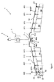
図1は、各翼における少なくとも1つの着陸用フラップを調整するための、本発明にかかる高揚力システム1の実施形態を示している。図1は、各翼(図1には示されていない)に配置された2つの着陸用フラップを図示している。とくに示されているものは、第1翼上の内側着陸用フラップA1および外側着陸用フラップA2と、第2翼上の内側着陸用フラップB1および外側着陸用フラップB2である。本発明にかかる高揚力システムにはまた、翼あたり1つまたは2つ以上の着陸用フラップが設けられる。高揚力システム1は、とくに作動レバー等の作動ユニット3を有するパイロットインタフェースを通じて作動されて制御される。作動ユニット3は、中央駆動ユニット7を作動させるための作動ライン8を介して制御コマンドを中継するコントローラ/モニタ5に、機能的に連結されている。コントローラ/モニタ5は、中央コントローラ/モニタ5である。すなわちそれは、高揚力システムのいくつかの、とくに全ての調整装置A11、A12、B11、B12、A21、A22、B21、B22についての制御および監視機能部を有する。
FIG. 1 shows an embodiment of a
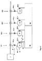
中央駆動ユニット7、すなわち機体エリアに配置されているものには、1つ以上の駆動モータが設けられる。示された高揚力システムの実施形態において、駆動ユニット7は、たとえば油圧モータおよび電気モータによって実現される2つの駆動モータM−a、M−bを有する。さらに駆動ユニット7は、コントローラ/モニタ5からの個別のコマンド信号によって作動される駆動モータM−a、M−bに配置された少なくとも1つの制動装置を有することができる。図1に示された高揚力システムの実施形態において、駆動ユニット7は、コントローラ/モニタ5からのコマンド信号によってそれぞれ作動される2つの制動装置B−a、B−bを有する。少なくとも1つの制動装置は、所定の状態に応じて制動装置を作動させるコントローラ/モニタ5に機能的に連結され、それによって回転シャ
フト伝動機構11、12をロックすることができる。駆動モータまたはいくつかの駆動モータのうちの1つにおける不具合は、中央駆動ユニット7または少なくとも1つの駆動モータに配置された駆動モータコントローラによって除去される。
One or more drive motors are provided in the
図1に示されているように、中央駆動ユニット7は、油圧モータHおよび電気モータによって与えられた電力レベルが加算されて回転駆動シャフト11、12に伝達されるように油圧モータM−aおよび電気モータM−bの出力部に連結された差動装置を有することができる。図1に示された本発明にかかる高揚力システムの典型的な実施形態には、さらにコントローラ/モニタ5に機能的に連結された2つの制動装置B−a、B−bが備わっている。コントローラ/モニタ5は、所定の状態に応じて制動装置B−a、B−bを作動させるように設計され、回転シャフト伝動機構11、12をロックするのを可能とする。示された典型的な実施形態において、2つの駆動モータのうちの1つ、たとえば油圧モータHまたは電気モータが止められると、中央駆動ユニット7は、油圧モータHおよび電気モータによって与えられた各電力レベルに基づく、差動装置にしたがって動作停止された駆動モータに関連する量だけ低減された電力を消す。
As shown in FIG. 1, the
2つの回転駆動シャフト11、12の全ては、翼あたり少なくとも1つのフラップA1、A2またはB1、B2を作動させるために中央駆動ユニット7に連結されている。2つの回転駆動シャフト11、12は、それらを互いに同期させる中央駆動ユニット7に連結されている。対応する制御コマンドに応じて、中央駆動ユニット7は、回転駆動シャフトに連結されている各フラップの調整装置のサーボ運動を実行するように回転駆動シャフト11、12を回転させる。負荷制限装置またはトルク制限装置Tは、駆動ユニット7に近接して設置された回転駆動シャフト11、12のシャフト部分内に一体化される。
All of the two
少なくとも1つの調整装置は、フラップの調整目的で各フラップA1、A2またはB1、B2に連結されている。図1に示された高揚力システムにおいて、2つの調整装置のそれぞれは、各フラップに、具体的には内側フラップA1およびB1に調整装置A11、A12またはB11、B12が、外側フラップA2およびB2に調整装置A21、A22またはB21、B22が配置されている。各フラップを作動させる少なくとも1つの調整装置は、以下、調整ステーションと称される。 At least one adjusting device is connected to each flap A1, A2 or B1, B2 for flap adjustment purposes. In the high lift system shown in FIG. 1, each of the two adjusting devices is on each flap, specifically on the inner flaps A1 and B1 with adjusting devices A11, A12 or B11, B12 on the outer flaps A2 and B2. Adjustment devices A21, A22 or B21, B22 are arranged. The at least one adjustment device that activates each flap is hereinafter referred to as an adjustment station.
調整装置A11、A12、B11、B12、A21、A22、B21、B22が以下に記載される。ここで各調節装置において同一の機能を有する種々調整装置の部品は、同じ参照符号で表示される。 The adjusting devices A11, A12, B11, B12, A21, A22, B21, B22 are described below. Here, parts of various adjusting devices having the same function in each adjusting device are denoted by the same reference numerals.
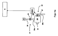
調整装置A11、A12、B11、B12、A21、A22、B21、B22のそれぞれは、アクチュエータまたは速度変換ギア20と、アクチュエータ20を調整フラップに運動学的に連結するための調整運動部VKと、任意の位置センサ22と、ギアリング25と、少なくとも2つの負荷センサ31、32とを有する。ギアリング25は、アクチュエータ20の入力部における入力要素20aまたは下方駆動リンクに入力運動を与えるように、各駆動シャフト11、12の運動を、アクチュエータ20に連結された駆動部分または駆動要素24の運動に変える。
Each of the adjustment devices A11, A12, B11, B12, A21, A22, B21, B22 includes an actuator or
たとえば調整運動部VKは、各フラップが連結されているように案内経路(トラック)上で移動可能なキャリッジを有するトラックキャリッジ調整装置、または各フラップが連結されているように固定されたフラップ支点まわりに回転することができる調整レバーを有するドロップヒンジ調整装置の形態をとることができる。アクチュエータまたは速度変換ギア20は、各回転駆動シャフト11、12に機械的に連結され、各回転駆動シャフト11、12の回転運動を、各調整装置A11、A12、B11、B12、A21、A22、B21、B22に連結されたフラップエリアの調整運動に変える。フラップの各調整装
置A11、A12、B11、B12、A21、A22、B21、B22には、各フラップの現在位置を測定することでライン(図示されていない)を介してこの位置値をコントローラ/モニタ5に送る位置センサ22が設けられる、と提供される。
For example, the adjustment motion part VK is a track carriage adjustment device having a carriage movable on a guide path (track) so that the respective flaps are connected, or around a flap fulcrum fixed so that the respective flaps are connected. It can take the form of a drop hinge adjustment device having an adjustment lever that can be rotated to the right. The actuator or
アクチュエータ20の出力部は、アクチュエータ20を連結するためのフラップサイド連結装置27に連結されかつ各フラップA1、A2、B1、B2を調整するためにフラップサイド連結装置27に運動を与えるように、入力部において入力要素20aを介して導入される運動を使用する出力要素または出力レバー20bを有する。入力要素20aおよび出力要素20bは、機械的機能を有する部品として設計されている。とくに入力要素20aまたは出力要素すなわち伝達要素20bは、ここでは回転シャフトおよび/または圧縮引張ロッドとして設計される。入力要素20aは、機械力をアクチュエータに導入するトルクまたは力伝達部品であり、一方、出力要素20bは、アクチュエータ20によって発生されたトルクまたはアクチュエータ20によって発生された力を、連結装置27に、したがってフラップに伝達する。結果としてギアリング機能を有する機械的伝達機構は、入力要素20aと出力要素20bとの間に存在する。
The output of the
さらに回転シャフト伝動機構11または12の端部は、これもまたライン(図示されていない)によってコントローラ/モニタ5に機能的に連結され、このラインを介して現在値をコントローラ/モニタ5に送り、回転シャフト伝動機構11または12の端部が所定の範囲内で回転されているか否か、または回転駆動シャフト11または12の非対称回転位置が存在するか否かを指し示す非対称センサ23を備えることができる。
Furthermore, the end of the rotary
さらに各回転駆動シャフト11または12には、各伝動機構11または12の作動を遮断することができる翼端制動部WTBを備えることができる。1つの翼端制動部WTBは、ここではとくに各翼の外側領域に存在する回転駆動シャフト11または12の1つの位置に配置されている。各翼端制動部WTBは、ライン(これも図示されていない)を介してコントローラ/モニタ5に機能的に連結され、コントローラ/モニタ5によってこのラインを介して作動されて動作される。動作中、翼端制動部WTBの標準の出力状態は、回転駆動シャフト11または12の回転に干渉しない非作動状態である。コントローラ/モニタ5からの対応する制御信号に応じて、翼端制動部WTBは、それぞれ配置された回転駆動シャフト11または12をロックするように作動される。
Furthermore, each
ドロップヒンジ調整装置として構成された調整運動部VKにおいて、フラップサイド連結装置27は、とくに回転可能なサーボレバー、および回転アクチュエータまたは回転式アクチュエータによるアクチュエータによって形成される。調整運動部VKが、各フラップが連結されているように案内経路(トラック)上で移動可能なキャリッジを有するトラックキャリッジ調整装置として構成されている場合には、フラップサイド連結装置27は、ワゴンと、それにまたはロッドおよびこの場合にはとくにスピンドル駆動部に連結されたレバーとの結合体から構成される。ワゴンは、ここでは主翼に固定された案内経路(トラック)上に移動可能に搭載される。双方の場合において、フラップは、レバー配列または案内経路からなることができるように主翼上に配置されたフラップガイドによって案内される。
In the adjusting motion part VK configured as a drop hinge adjusting device, the flap
本発明によれば、各調整装置A11、A12、B11、B12、A21、A22、B21、B22は、一般に参照符号S1によっても符号が付される第1負荷センサS11−a、S12−a、S21−a、S22−aと、一般に参照符号S2によっても符号が付される第2負荷センサS11−b、S12−b、S21−b、S22−bとを備えている。第1負荷センサS11−a、S12−a、S21−a、S22−aおよび/または第2負荷センサS11−b、S12−b、S21−b、S22−bは、トルクセンサまたは力センサとすることができる。第1負荷センサS11−a、S12−a、S21−a、S22−
aは、一般に入力部31上に設けられ、各駆動要素26および/または各アクチュエータ20の入力要素20aおよび/または駆動要素26と入力要素20aとの間の連結部に配置される。第1負荷センサS11−a、S12−a、S21−a、S22−aは、アクチュエータ20の入力部に存在するかまたはアクチュエータ20の入力要素へと動かされるもしくは押付けられるように中央駆動ユニット7の作動に応じて生じる負荷を取得するように設計されている。第2負荷センサS11−b、S12−b、S21−b、S22−bは、各アクチュエータ20の出力要素20bおよび/または各フラップサイド連結装置27および/または出力要素20bと連結装置27との間の連結部に位置することができる。第2負荷センサS11−b、S12−b、S21−b、S22−bは、アクチュエータ20の出力部に存在するかまたはアクチュエータ20の出力要素へと動かされるかまたはフラップサイド連結装置27に押付けられるように中央駆動ユニット7の作動に応じて生じる負荷を取得するように設計されている。
According to the present invention, each of the adjusting devices A11, A12, B11, B12, A21, A22, B21, B22 is generally labeled with the reference sign S1 as well as the first load sensors S11-a, S12-a, S21. -A, S22-a, and second load sensors S11-b, S12-b, S21-b, S22-b, which are generally also denoted by reference numeral S2. The first load sensors S11-a, S12-a, S21-a, S22-a and / or the second load sensors S11-b, S12-b, S21-b, S22-b are torque sensors or force sensors. be able to. First load sensors S11-a, S12-a, S21-a, S22-
a is generally provided on the
これに関連して負荷は、一般にトルクおよび/または力を参照する。 In this context, the load generally refers to torque and / or force.
第1負荷センサS11−a、S12−a、S21−a、S22−aおよび第2負荷センサS11−b、S12−b、S21−b、S22−bは、それぞれ調整装置監視機能部40の調整装置評価機能部とライン(図示されていない)によって機能的に連結され、それぞれ測定された負荷の量についての現在の信号値を、このラインを介して調整装置監視機能部40に中継する。調整装置監視機能部40または個々の機能部は、中央コントローラ/モニタ5の一部とすることができる。代案として、調整装置監視機能部40または個々の機能部はまた、アクチュエータ20またはフラップに配置されたアクチュエータ20に近接して配置された局部、あるいは分散化されたコントローラ/モニタ41の一部とすることもできる。各調整装置または一群の調整装置における分散化されたコントローラ/モニタ41は、とくに分散化された方法で作動される高揚力システムのために設けられる。この場合、調整機構は、中央駆動ユニット7によって作動されないが、代わりに、中央コントローラ/モニタ5から単にコマンドを受信するが他の調整フラップに接続された駆動機構に機械的に連結されてはいない各駆動機構によって作動される。調整装置監視機能部40のさらなる機能部は、ここでは中央コントローラ/モニタ5に実装される。そのような分散化されたコントローラ/モニタ41は、主翼に固定されることができ、翼長方向における互いに異なる位置に配置することができる。1つの典型的な実施形態において、分散化されたコントローラ/モニタ41は、フラップが内部に延在している主翼の翼長区分において翼長方向に配置されている。各フラップのアクチュエータ20についての各分散化されたコントローラ/モニタ41は、ここでは図1における典型的な実施形態において2つの分散化されたコントローラ/モニタ41が各翼上に配置されるように設けられる。代案として、各アクチュエータ20およびとくに各調整装置のキャリア部分は、調整装置監視機能部40が実装される分散化されたコントローラ/モニタ41を収容することができる。各分散化されたコントローラ/モニタ41はまた、いくつかの調整装置のために設けられることもできる。
The first load sensors S11-a, S12-a, S21-a, S22-a and the second load sensors S11-b, S12-b, S21-b, S22-b are respectively adjusted by the adjustment device monitoring function unit 40. It is functionally connected to the device evaluation function by a line (not shown) and relays the current signal value for each measured amount of load to the regulator monitoring function 40 via this line. The coordinator monitoring function 40 or individual functions can be part of the central controller /
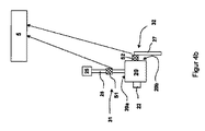
図4aおよび図4bにおける比較によって示されるように、調整装置の2つの負荷センサは、局部データ集線装置RDCに機能的に連結されるか(図4a)、または中央コントローラ/モニタ5に機能的に直接連結される(図4b)。図4aにかかる典型的な実施形態において、各調整フラップに接続された少なくとも1つの調整装置は、少なくとも1つの調整装置のそれぞれに近接して局部的に配置された各データ集線装置RDCを備えることができる。とくにこの典型的な実施形態においては、調整装置評価機能部および/または調整装置障害識別機能部は、局部データ集線装置RDCに実装される。
As shown by the comparison in FIGS. 4a and 4b, the two load sensors of the regulator are functionally coupled to the local data concentrator RDC (FIG. 4a) or functionally to the central controller /
調整装置監視機能部40は、調整装置評価機能部と、調整装置障害識別機能部とを有する。調整装置評価機能部は、負荷センサの信号を受信し、それらを評価する。すなわちセ
ンサ信号から対応する負荷値を得る。調整装置障害識別機能部は、分散化されたコントローラ/モニタ41または中央コントローラ/モニタ5の一部とすることができる。
The adjustment device monitoring function unit 40 includes an adjustment device evaluation function unit and an adjustment device failure identification function unit. The adjustment device evaluation function unit receives signals from the load sensor and evaluates them. That is, the corresponding load value is obtained from the sensor signal. The coordinator fault identification function can be part of a decentralized controller / monitor 41 or central controller /
障害状態が調整装置に割当てられたときに高揚力システムを再構成するために、調整装置障害識別機能部は、分散化されたコントローラ/モニタ41または中央コントローラ/モニタ5に一体化されることもできる高揚力システム再構成機能部に配置される。1つ以上の調整装置に対する少なくとも1つの障害状態の割当に応じて、そのような高揚力システム再構成機能部は、少なくとも1つの障害状態に対応する各障害を必要に応じて補償するように1つ以上の調整装置に再構成コマンドを生成する。
To reconfigure the high lift system when a fault condition is assigned to the coordinator, the coordinator fault identification function may be integrated into the decentralized controller / monitor 41 or central controller /
そのような再構成コマンドは、調整装置の動作停止を含むことができる。再構成コマンドはまた、もはや調整装置を作動させないことを含むこともできる。この種の再構成コマンドは、調整装置の作動中に中央コントローラ/モニタ5が非作動コマンドを考慮に入れるように、中央コントローラ/モニタ5に送られる。高揚力システムは、ここではたとえば調整装置の冗長な部品を介して、特定の障害を許容し、いかなる障害が生じても調整装置にコマンドを送らないように設計される。そのようなコマンドを形成したとき、高揚力システム再構成機能部は、全ての調整装置の障害状態を考慮に入れる。高揚力システムの他の典型的な実施形態において、分散化されたコントローラ/モニタ41は、配置された調整装置のそれぞれを動作停止させるためのコマンドのようなものをそれ自身が生成するように設計される。しかし、集中型のコントローラ/モニタ5は、他の調整装置についての追加の再構成コマンドを生成するように他の調整装置についての悪影響を考慮した集中型の高揚力システム再構成機能部を一体化する。
Such a reconfiguration command can include stopping the coordinator. The reconfiguration command can also include no longer actuating the regulator. This type of reconfiguration command is sent to the central controller /
本発明によれば、第1負荷センサS11−a,S12−a,S21−a,S22−aおよび第2負荷センサS11−b,S12−b,S21−b,S22−bは、調整装置に障害状態を割当てるために負荷センサによって確認されたセンサ値を受信するように調整装置障害識別機能部に機能的に連結されている。とくに第1負荷センサと第2負荷センサとのセンサ値が、それぞれ調整装置障害識別機能部における少なくとも1つの制限値と比較され、この制限を上回るか下回る第1負荷センサと第2負荷センサとの信号値が、調整装置の障害状態の決定に使用される、とここでは提供される。 According to the present invention, the first load sensors S11-a, S12-a, S21-a, S22-a and the second load sensors S11-b, S12-b, S21-b, S22-b are included in the adjusting device. Functionally coupled to the coordinator fault identification function to receive sensor values identified by the load sensor to assign fault conditions. In particular, the sensor values of the first load sensor and the second load sensor are respectively compared with at least one limit value in the adjustment device failure identification function unit, and the first load sensor and the second load sensor exceed or fall below this limit. It is provided here that the signal value is used to determine the fault condition of the regulator.
この目的を達成するために、調整装置障害識別機能部は、それぞれそれらに配置されたアクチュエータ20の伝達機能を使用および/または格納することができる。これらは、アクチュエータの効率と、アクチュエータのモデルに依存して、ギア比とを含む。
In order to achieve this object, the coordinator fault identification functions can use and / or store the transmission functions of the
とくに調整装置障害識別機能部は、以下の障害場面を確認するように構成される。 In particular, the adjustment device failure identification function unit is configured to confirm the following failure scenes.
無負荷障害場面Aの場合、所定の無負荷制限、または無負荷制限未満の負荷センサ値が生じる場合に各アクチュエータ20の入力部31または出力部32において無負荷もしくは少なくとも常時無負荷がアクティブもしくは存在していると考えられる無負荷制限に基づき、各アクチュエータ20の入力部31または出力部32におけるおおよそ無負荷状態が測定される。とくに無負荷制限は、アクチュエータの最大常時負荷の、またはここではアクチュエータの入力部31もしくは出力部32において生じる負荷の1/5、とくに1/5を測定することができる。値が無負荷制限未満まで降下したかを検証するために、第1負荷センサS11−a、S12−a、S21−a、S22−aが、センサ信号を調整装置障害識別機能部に伝達して第1負荷センサの位置における最大常時負荷の1/5未満であるとして定義された負荷を指し示し、第2負荷センサS11−b、S12−b、S21−b、S22−bが、第2負荷センサの位置における最大常時負荷の1/5未満であるとして定義された負荷を指し示す、ということもまた提供される。
In the case of no-load failure scene A, no load or at least always no load is active or present at the
入力部31、出力部32、および/またはフラップガイドの機械的伝達部分の破損または機械的分断(切断)の場合、無負荷が負荷センサ31、32のいずれかに加えられ、その結果、第1負荷センサS11−a、S12−a、S21−a、S22−aおよび第2負荷センサS11−b、S12−b、S21−b、S22−bは、無負荷制限未満である値を指し示す。したがってこれは、とくに各調整装置A11、A12、B11、B12、A21、A22、B21、B22の力またはトルク伝達鎖におけるこれらの部品の少なくとも1つの分断と同様に、駆動要素26、入力要素20a、出力要素20b、およびフラップサイド連結装置27の破損に適用する。
In case of breakage or mechanical breakage (cutting) of the
本発明によれば、調整装置障害識別機能部に送られた第1負荷センサS11−a、S12−a、S21−a、S22−aおよび第2負荷センサS11−b、S12−b、S21−b、S22−bのセンサ信号が低すぎるときには、入力部31の機械的伝達部分および/または出力部32の伝達部分の破損または「切断」障害状態が、各調整装置A11、A12、B11、B12、A21、A22、B21、B22に割当てられ、それにより、各調整装置A11、A12、B11、B12、A21、A22、B21、B22が機能しないという信号を送る。
According to the present invention, the first load sensors S11-a, S12-a, S21-a, S22-a and the second load sensors S11-b, S12-b, S21- sent to the adjusting device failure identification function unit. b, when the sensor signal of S22-b is too low, the mechanical transmission part of the
オプションとして、航空機によって現在占められている動作モードが、この障害が重大ではない場合のものであるか否かを、調整装置障害識別機能部が確認する、と提供される。とくに航空機が整備中であるか否かの問合せまたは条件は、このために重大であり得る。したがってセンサ信号が低すぎかつ航空機が同時に重大状態ではない場合には、各調整装置A11、A12、B11、B12、A21、A22、B21、B22を動作停止およびもはや作動させないこともまた含むことができる高揚力システムを再構成するための措置が行われる。 As an option, it is provided that the coordinator fault identification function checks whether the mode of operation currently occupied by the aircraft is that this fault is not critical. In particular, an inquiry or condition as to whether an aircraft is being serviced can be critical for this. Thus, if the sensor signal is too low and the aircraft is not at the same time critical, it may also include deactivating and no longer deactivating each regulator A11, A12, B11, B12, A21, A22, B21, B22. Measures are taken to reconfigure the high lift system.
調整装置障害識別機能部はまた、駆動トルクの全体が影響を受ける調整ステーションに加えられる間におけるように出力要素20bおよび/またはフラップサイド連結装置27および/またはフラップガイドを意味する調整装置A11、A12、B11、B12、A21、A22、B21、B22の出力部32におけるフラップの故障にとくに関する過負荷障害場面Bを含むこともできる。この障害場面は、一般にフラップを故障させる。この種の故障は、伝動機構の破損をもたらす過負荷をもたらし得る。この場合、各調整装置A11、A12、B11、B12、A21、A22、B21、B22によって各フラップに接続されたそれらのアクチュエータによって発生される力および/またはトルクの合計は、アクチュエータの出力部に存在する。この事実の測定を行うために、本発明は、一般に第2負荷センサS2が負荷L2に対応する信号値を生成し、信号値が第2負荷センサS2の位置における常時負荷に対応する所定の制限を上回った場合に、調整装置障害識別機能部に伝達する状態を提供する。1つの状態は、とくに問題になっているアクチュエータに与えられる常時負荷、とくに最大常時負荷、とくに最大許容常時負荷を上回った、というものであり得る。最大許容常時負荷は、アクチュエータ動作を対象とした範囲、とくに出力部32における範囲の上限である。これは、この範囲が出力部32の部品において力および/またはトルクを許容するということを意味する。この力および/またはトルクの範囲は、とくに第2負荷センサS11−b、S12−b、S21−b、S22−bが配置される出力部32の部品において許容される。最大常時負荷は、この位置における最大許容力または最大許容トルクである。したがってこの過負荷障害場面Bにおいて、第2負荷センサS11−b、S12−b、S21−b、S22−bは、とくに第2負荷センサS2の位置における最大常時負荷または最大許容力または最大許容トルクまたは通常動作中に実際に生じる最大負荷を上回る負荷に対応する調整装置障害識別機能部に、センサ信号を伝達する。これらの取り得る最大負荷は、以下、Lmaxとラベル付けされ、したがってこれらの状態は、L2>Lmaxで記載される。
The adjusting device fault identification function also means adjusting devices A11, A12, which means the
そのようなセンサ値は、過負荷障害場面Bについての唯一の指標である。しかし、それは調整装置A11、A12、B11、B12、A21、A22、B21、B22の出力部32またはそれらに配置された各調整フラップにおける故障の場面が存在する場合には、第1負荷センサS11−a、S12−a、S21−a、S22−aが範囲
L1=(L2/i)±k1
に存在する負荷を確認するようにさらなる状態として規定される。
Such a sensor value is the only indicator for overload failure scene B. However, if there is a failure scene in the
It is defined as a further state to check the load present in
この場合において、
・変数「i」は、アクチュエータが入力部31と出力部32との間で実現するギア比であり、
・定数「k1」は、アクチュエータの効率を考慮に入れた、測定された各値L2/iの前後の範囲を定義する量である。
In this case,
The variable “i” is a gear ratio realized by the actuator between the
The constant “k 1 ” is an amount that defines the range around each measured value L 2 / i taking into account the efficiency of the actuator.
とくに定数k1は、入力部31、とくに第1負荷センサS11−a、S12−a、S21−a、S22−aの位置において許容されるかまたは実際に通常動作中に生じる最大常時負荷の15%とすることができる。
In particular, the constant k 1 is allowed at the position of the
したがって本発明によれば、調整装置障害識別機能部は、一般に以下の場合に、調整装置A11、A12、B11、B12、A21、A22、B21、B22の出力部32または付随する調整フラップの調整運動部VKに故障の場面を割当てる。
Therefore, according to the present invention, the adjustment device failure identification function unit generally adjusts the
・第2負荷センサS2が負荷L2に対応する信号値を生成し、それが第2負荷センサS2の位置における常時負荷に対応する所定の制限を上回った場合、とくに負荷L2が所定の最大負荷を上回ることが提供されるようにすなわちL2>Lmaxである場合に、調整装置障害識別機能部に送信する場合。 - second load sensor S2 generates a signal value corresponding to the load L 2, if it exceeds a predetermined limit, corresponding to the constant load in the position of the second load sensor S2, especially maximum load L 2 is given When sending to the coordinator fault identification function as provided to exceed the load, ie L 2 > L max .
・第1負荷センサS1によって測定された負荷L1が、とくにアクチュエータ20のギア比および効率を考慮に入れた、第2負荷センサS2によって測定された負荷L2に対応する各調整運動部VKの入力部31の動作範囲に存在する場合、またはL1=(L2/i)±k1である場合。
· Load L1 measured by the first load sensor S1, in particular a gear ratio and efficiency of the
これらの状態が満たされたとき、調整装置障害識別機能部は、出力要素20bおよび/またはフラップサイド連結装置27を意味するフラップの調整装置A11、A12、B11、B12、A21、A22、B21、B22の出力部32に故障の場面を割当てる。
When these conditions are fulfilled, the adjusting device fault identification function unit is the flap adjusting device A11, A12, B11, B12, A21, A22, B21, B22 which means the
本発明によれば、調整装置障害識別機能部は、ギア障害場面Cの場合、第1負荷センサS1によって測定された負荷L1が、第2負荷センサ(S2)によって測定された負荷(L2)に名目上由来する各調整運動部(VK)の入力部(31)の動作範囲を上回る場合、アクチュエータまたはS1とS2の間に存在する各調整装置の一部によって故障の場面を確認することができる。とくに第1負荷センサS1によって測定された負荷L1は、アクチュエータ20のギア比を考慮に入れた、第2負荷センサS2によって測定された負荷L2の2倍を上回る、と提供される。さらに調整装置は、第1負荷センサS1が状態
L1>(L2/i)+k2
が満たされる負荷値L1を確認した場合、アクチュエータ20についての故障場面が割当てられる、ととくに提供される。定数k2は、とくにアクチュエータ20の効率を考慮に入れるのを可能とする。この状態において、式(L2/i)+k2は、アクチュエータ20によって実現されるギア比を考慮に入れた、出力部32に存在する負荷値に対応する負荷値L1を記載する。過負荷障害場面Bの状態L1>(L2/i)±k1からギア障害場面Cの状態L1>(L2/i)+k2を識別するために、定数k2が定数k1よりも大きい、ととくに提供される。とくに定数k2は、定数k1よりも大きい、とくに定数k1
の2倍である、とここでは提供される。空気力が出力部32に作用することから、検証がS2のセンサ値について実行される必要はなく、第1負荷センサS1についての測定値と測定値との間に明らかな分析的相関はない。
According to the present invention, the adjusting device failure identification module in the case of the gear failure scene C, the load L 1 measured by the first load sensor S1 is measured load by the second load sensor (S2) (L 2 ), If the operating range of the input part (31) of each adjustment movement part (VK) that is nominally derived from the actuator is exceeded, the failure scene is confirmed by the actuator or a part of each adjustment apparatus existing between S1 and S2. Can do. In particular the load L 1 measured by the first load sensor S1 is put gear ratio of the
If confirms the load value L 1 which is satisfied, a fault situation of the
It is provided here that it is twice as large. Since aerodynamic forces act on the
調整装置障害識別機能部はまた、たとえばアクチュエータ20における摩擦増加、一般には各アクチュエータまたは第1負荷センサS1と第2負荷センサS2との間に存在する伝達部分に関する制限された性能の状態等の効率低下を含む伝達障害場面Dが、調整装置において検出または割当てられる機能を有することもできる。本発明によれば、調整装置障害識別機能部は、第1負荷センサS1によってそれぞれ測定された負荷値L1と第2負荷センサS2によってそれぞれ測定された負荷値L2とから比L1/L2を形成し、この比が所定の制限k3よりも低いときに測定する場合に、アクチュエータ20または第1負荷センサS1と第2負荷センサS2との間に存在する伝達部分に、制限された性能の状態を割当てる。制限k3は、ここではとくにk3 *・(L2/L1)nomから構成される。ここでk3=k3 *・(L2/L1)nomであり、比(L2/L1)nomは、名目上のまたは通常の効率において所定の無傷なアクチュエータをもたらす名目上の負荷比である。結果として状態は、式L2/L1<k3 *・(L2/L1)nomによって定式化されるかまたはそれから得られる。
The regulator fault identification function also provides efficiencies such as, for example, increased friction at the
状態L2<k3・(L2/L1)nom・L1および/またはL1>1/k3・(L1/L2)nom・L2はまた、状態L2/L1<k3 *・(L2/L1)nomの代わりに最初に述べた式の数学的改変として使用される。 State L 2 <k 3 · (L 2 / L 1 ) nom · L 1 and / or L 1 > 1 / k 3 · (L 1 / L 2 ) nom · L 2 is also in state L 2 / L 1 < Instead of k 3 * · (L 2 / L 1 ) nom , it is used as a mathematical modification of the first mentioned equation.
さらに調整装置障害識別機能部は、以下に明記される特定の状態が満たされた場合に、これに関連して第1センサ障害場面Eとしても称されるたとえばいわゆるセンサ切断等の機械的センサ障害が第1負荷センサS1に割当てられる機能を有することができる。これは、第1負荷センサS1が所定の無負荷信号値を下回り、第2負荷センサS2が負荷を指し示す所定の負荷信号値を上回ったことを調整装置障害識別機能部が測定する場合である。無負荷信号値は、とくに無負荷障害場面Aに関して記載されたものとして定義される。調整装置障害識別機能部は、アクチュエータの各起動の関数としておよび/またはサイズおよび/または起動のためにアクチュエータに送られるコマンド信号の種類の関数としての上述した状態を満たすように第2負荷センサS2によって上回られる負荷信号値を測定する機能を有することができる。 Further, the adjustment device failure identification function unit is also referred to as a first sensor failure scene E in association with a specific state specified below, for example, a mechanical sensor failure such as so-called sensor disconnection. Can have a function assigned to the first load sensor S1. This is a case where the adjusting device failure identification function unit measures that the first load sensor S1 is below a predetermined no-load signal value and the second load sensor S2 is above a predetermined load signal value indicating the load. The no-load signal value is defined specifically as described for no-load fault scene A. The adjusting device fault identification function is adapted to satisfy the above-mentioned condition as a function of each activation of the actuator and / or as a function of the size and / or the type of command signal sent to the actuator for activation. It is possible to have a function of measuring a load signal value that is exceeded by.
同様にして、調整装置障害識別機能部は、第1センサ障害場面Eに関して逆に定義される以下に挙げられる特定の状態が満たされた場合に、とくにいわゆるセンサ切断等の機械的センサ障害(第2センサ障害場面F)が第2負荷センサS2に割当てられる機能を有することができる。この場合、この割当は、第2負荷センサS2が所定の無負荷信号値を下回り、第1負荷センサS1が負荷を指し示す所定の負荷信号値を上回ったことを調整装置障害識別機能部が測定する場合に生じる。無負荷信号値は、とくに無負荷障害場面Aに関して記載されたものとして定義される。調整装置障害識別機能部は、アクチュエータの各起動の関数としておよび/またはサイズおよび/または起動のためにアクチュエータに送られるコマンド信号の種類の関数としての上述した状態を満たすように第1負荷センサS1によって上回られる負荷信号値を測定する機能を有することができる。 Similarly, the adjustment device failure identification function unit, in particular, satisfies the following specific condition defined in reverse with respect to the first sensor failure scene E, in particular, a mechanical sensor failure (the first sensor disconnection or the like) The two-sensor failure scene F) can have the function assigned to the second load sensor S2. In this case, this allocation is determined by the adjusting device failure identification function unit that the second load sensor S2 is below a predetermined no-load signal value and the first load sensor S1 is above a predetermined load signal value indicating the load. Occurs in some cases. The no-load signal value is defined specifically as described for no-load fault scene A. The adjusting device fault identification function is arranged so that the first load sensor S1 satisfies the above-mentioned condition as a function of each activation of the actuator and / or as a function of the size and / or the type of command signal sent to the actuator for activation. It is possible to have a function of measuring a load signal value that is exceeded by.
高揚力システム再構成機能部は、調整装置障害識別システムによって確認されたまたは部品もしくは部品結合体に対する障害状態の割当に基づく障害場面の機能として、高揚力システムを、信頼性を備えるシステム構成へと再構成するために再構成措置を導入することができる。 The high-lift system reconfiguration function unit converts the high-lift system into a reliable system configuration as a function of failure scenes confirmed by the adjustment device failure identification system or based on assignment of failure states to parts or component assemblies. Reconfiguration measures can be introduced to reconfigure.
調整装置A11、A12、B11、B12、A21、A22、B21、B22のアクチ
ュエータが中央コントローラ/モニタ5から電線を介してコマンドを送られ、2つのアクチュエータ20がサーボフラップを作動させるためにサーボフラップに接続された高揚力システムにおいて、調整装置における調整装置障害識別機能部によって各調整装置A11、A12、B11、B12、A21、A22、B21、B22が不機能状態(無負荷障害場面A)を割当てられた後にはフラップがもはや作動されない、と提供される。コントローラの非対称性を回避するために、航空機の長手方向軸に関して障害場面によって影響を受ける調整フラップに対称的に配置されたサーボフラップがもはや作動されない、とここではさらに提供される。さらにこの場面に関してアクチュエータ20において与えられる制動部が、現在の調整状態において調整フラップをロックするように起動される、と提供される。
The actuators of the adjusting devices A11, A12, B11, B12, A21, A22, B21, B22 are sent commands from the central controller /
アクチュエータが共通の回転シャフト11、12を介して駆動され、調整運動部VKの各部品がフェイルセーフ機構を備えている場合、高揚力システム再構成機能部は、問題となっている調整装置が作動を継続することを提供することができる。
When the actuator is driven through the common
中央コントローラ/モニタの電線を介して調整装置A11、A12、B11、B12、A21、A22、B21、B22のコマンドがアクチュエータに送られるような高揚力システムにおいて、無負荷障害場面Aについて記載されたものと同じ任意の測定は、所定の過負荷障害場面Bの割当に導入される。調整装置A11、A12、B11、B12、A21、A22、B21、B22が回転駆動シャフト11、12を介して機械的に作動される図1にかかる高揚力システムにおいて、調整装置における過負荷障害場面Bの割当の場合、システム内部力の対立を回避するために、システムがモータ制動部M−a、M−bおよび/または翼端制動部WTBを介してロックされる、と提供される。
Describes no-load fault scene A in a high lift system where the commands of adjusting devices A11, A12, B11, B12, A21, A22, B21, B22 are sent to the actuator via the central controller / monitor wires The same optional measurements are introduced into the allocation of a given overload fault scene B. In the high lift system according to FIG. 1 in which the adjusting devices A11, A12, B11, B12, A21, A22, B21, B22 are mechanically actuated via the
集中的に、すなわち回転シャフト11、12を介して作動される高揚力システムにおいて、コントローラ/モニタ5または高揚力システム再構成機能部が、位置センサによって取得された実際の位置からのコントローラ/モニタ5によって測定されたセット位置の許容できない偏差が存在する場合に双方のシャフトトレーン11、12をロックするように、翼端制動部WTBおよび少なくとも1つの制動装置B−a,B−bに作動信号を送る、と提供されてもよい。
In a high lift system operated centrally, i.e. via the rotating
さらに高揚力システム再構成機能部は、右翼の第1負荷センサS1_RWによって測定される信号値L1_RWが、加えられた負荷について上述した調整装置に関して対称的に配置された左翼の調整装置における第1負荷センサS1_LWによって生成された信号値と比較されるように構成される。調整装置障害識別機能部は、ここでは信号値L1_RW、L1_LWに基づきそれぞれ測定された負荷L1、L2が最小値だけ互いに外れた場合に、たとえば低負荷であっても各右フラップに故障場面を割当てることができる。したがってこの故障場面を割当てるように、状態
M−A_RH>M−A_KH+k5
が満たされなければならない。
In addition, the high lift system reconfiguration function unit is configured such that the signal value L1_RW measured by the right wing first load sensor S1_RW is arranged symmetrically with respect to the adjusting device described above with respect to the applied load. It is configured to be compared with the signal value generated by the sensor S1_LW. Here, the adjustment device failure identification function unit detects a failure scene in each right flap even if the load L 1 and L 2 measured based on the signal values L1_RW and L1_LW deviate from each other by a minimum value, for example, even at a low load. Can be assigned. Therefore, the state MA-RH> MA-KH + k 5 so as to assign this failure scene.
Must be satisfied.
差異は、負荷の関数として常に指示または測定される。故障の場面は、反対に各左フラップについて確認される。 The difference is always indicated or measured as a function of load. The failure scene is confirmed for each left flap, on the contrary.
Claims (19)
・アクチュエータ(20)と、前記前記アクチュエータ(20)を前記調整フラップ(A1、A2;B1、B2)に運動学的に連結する調整運動部(VK)と;
・前記調整フラップ(A1、A2;B1、B2)の作動に起因して前記アクチュエータ(20)の入力部において生じる負荷を測定するために、前記アクチュエータ(20)の入力部(31)に配置された第1負荷センサ(S1;S11−a、S12−a、S21−a、S22−a)と;
・前記調整フラップ(A1、A2;B1、B2)の作動に起因して前記アクチュエータ(20)の出力部(32)において生じる負荷を測定するために、前記アクチュエータ(20)の出力部(32)に配置された第2負荷センサ(S2;S11−b、S12−b、S21−b、S22−b)と
を備え、
前記第1負荷センサ(S1)と前記第2負荷センサ(S2)とは、前記調整装置(A11〜B22)の機能的状態を監視するように、前記第1負荷センサ(S1)と前記第2負荷センサ(S2)とによって確認されたセンサ値を伝達するために調整装置障害識別機能部に機能的に連結されている
ことを特徴とする、調整装置。 Adjustment devices (A11, A12, B11, B12, A21, A22, B21, B22) connected to aircraft adjustment flaps (A1, A2; B1, B2), wherein the adjustment devices (A11 to B22) are
An actuator (20) and an adjusting motion part (VK) kinematically connecting the actuator (20) to the adjusting flaps (A1, A2; B1, B2);
Arranged at the input (31) of the actuator (20) to measure the load generated at the input of the actuator (20) due to the operation of the adjustment flaps (A1, A2; B1, B2) The first load sensor (S1; S11-a, S12-a, S21-a, S22-a);
An output part (32) of the actuator (20) for measuring the load generated at the output part (32) of the actuator (20) due to the operation of the adjusting flaps (A1, A2; B1, B2); A second load sensor (S2; S11-b, S12-b, S21-b, S22-b) disposed in
The first load sensor (S1) and the second load sensor (S2) are configured to monitor the functional state of the adjusting devices (A11 to B22) and the second load sensor (S1). An adjusting device, characterized in that it is functionally connected to the adjusting device fault identification function unit for transmitting the sensor value confirmed by the load sensor (S2).
前記第1負荷センサ(S1)と前記第2負荷センサ(S2)とは、前記第1負荷センサ(S1)と前記第2負荷センサ(S2)とによって確認されたセンサ値を伝達するために、調整装置障害識別機能部に機能的に連結され、
前記調整装置障害識別機能部は、前記調整装置の機能的状態を監視することが可能なように設計されている
ことを特徴とする、調整装置結合体。 An adjustment combination that is a combination of the adjustment device according to claim 1 (A11 to A22, B11 to B22) and the adjustment device failure identification function unit,
In order to transmit the sensor value confirmed by the first load sensor (S1) and the second load sensor (S2), the first load sensor (S1) and the second load sensor (S2) Functionally linked to the coordinator fault identification function,
The adjustment device combination is characterized in that the adjustment device failure identification function unit is designed to be able to monitor a functional state of the adjustment device.
請求項2記載の調整結合体。 The adjustment device failure identification function unit compares the sensor values of the first load sensor (S1) and the second load sensor (S2) with at least one limit value, thereby the first load sensor (S1). ) And the second load sensor (S2) determine whether or not the adjustment device has a failure state based on whether the signal value exceeds or falls below the limit value.
The adjustment combination according to claim 2.
前記調整装置障害識別機能部は、前記各調整装置(A11〜A22、B11〜B22)に、不機能状態(無負荷障害場面A)を割当てる、
請求項2または3記載の調整結合体。 In the scene (A) where the first load sensor (S1) and the second load sensor (S2) each detect a value less than the no-load limit,
The adjustment device failure identification function unit assigns a non-functional state (no load failure scene A) to each of the adjustment devices (A11 to A22, B11 to B22).
4. The adjusted combination according to claim 2 or 3.
前記第2負荷センサ(S2)は、前記第2負荷センサ(S2)の位置における最大の所定または実際の常時負荷に対応する値の1/5未満である無負荷制限未満を測定することで前記調整装置障害識別機能部にセンサ信号を送信する場合、値が前記無負荷制限未満まで降下したとする、
請求項1〜4何れか一項記載の調整結合体。 The first load sensor (S1) measures less than a no-load limit that is less than 1/5 of a value corresponding to the maximum predetermined or actual constant load at the position of the first load sensor (S1). Send the sensor signal to the adjustment device failure identification function unit,
The second load sensor (S2) measures less than a no-load limit that is less than 1/5 of a value corresponding to the maximum predetermined or actual constant load at the position of the second load sensor (S2). When transmitting a sensor signal to the adjustment device failure identification function unit, the value drops below the no-load limit,
The adjustment coupling body as described in any one of Claims 1-4.
請求項5記載の調整結合体。 The non-functional state assigns the condition that the aircraft is under maintenance at the same time as the value falls below the no-load limit to a predetermined suitability,
6. The adjustment combination according to claim 5.
前記第1負荷センサ(S1)によって測定された負荷L1が、第2負荷センサ(S2)によって測定された前記負荷(L2)に対応する前記各調整運動部(VK)の前記入力部(31)の動作範囲に存在する場合に、
前記調整装置障害識別機能部は、前記調整装置(A11〜A22、B11〜B22)に障害状態を割当てる、
請求項1〜6何れか一項記載の調整結合体。 It said second load sensor (S2) generates a signal value corresponding to the load L 2 above the predetermined limit value corresponding to the constant load at a position of the second load sensor (S2), and the adjusting device failure identification Each of the adjustment motion units corresponding to the load (L 2 ) measured by the second load sensor (S 2) when the load L 1 measured by the first load sensor (S 1) is transmitted to the function unit (VK) in the operating range of the input unit (31),
The adjustment device failure identification function unit assigns a failure state to the adjustment devices (A11 to A22, B11 to B22).
The adjustment coupling body as described in any one of Claims 1-6.
請求項7記載の調整結合体。 The predetermined limit value for the constant load at the position of the second load sensor (S2) is a predetermined maximum load (L max ) for the output unit (32).
The adjustment combination according to claim 7.
前記調整装置障害識別機能部は、前記各調整装置(A11〜A22、B11〜B22)に障害状態を割当てる、
請求項1〜8何れか一項記載の調整結合体。 The signal values for the load (L 1) of the input unit generated by the first load sensor (S1) (31) is, from the second to the said load measured by the load sensor (S2) (L 2) When the value confirmed by the coordinator failure identification function unit is exceeded,
The adjustment device failure identification function unit assigns a failure state to each of the adjustment devices (A11 to A22, B11 to B22).
The adjustment coupling body as described in any one of Claims 1-8.
請求項8記載の調整結合体。 The first said load L 1 measured by the load sensor (S1) is twice the actuator (20) the load measured by the second load sensor by considering the gear ratio (S2) of L 2 Exceeding
The adjustment combination according to claim 8.
第2負荷センサ(S2)によって確認された負荷(L2)に対する、前記第1負荷センサによって確認された前記負荷(L1)の比L1/L2が、所定の制限値を上回った場合に、
前記調整装置障害識別機能部は、前記アクチュエータ(20)、または前記第1負荷センサ(S1)と前記第2負荷センサ(S2)との間に存在する伝達部分に、伝達障害場面(D)としての障害状態を割当てる、
請求項1〜10何れか一項記載の調整結合体。 The adjusting device failure identification function unit has measured that the load confirmed by the first load sensor exceeds a predetermined limit value and the load confirmed by the second load sensor falls below a predetermined limit value. Or the ratio L 1 / L 2 of the load (L 1 ) confirmed by the first load sensor to the load (L 2 ) confirmed by the second load sensor (S 2 ) is a predetermined limit value If it exceeds,
The adjustment device failure identification function unit is configured as a transmission failure scene (D) in the transmission portion existing between the actuator (20) or the first load sensor (S1) and the second load sensor (S2). Assign a failure status of
The adjustment coupling body as described in any one of Claims 1-10.
請求項1〜11何れか一項記載の調整結合体。 A position sensor (22) is arranged in the adjustment movement part (VK) so as to obtain the position of the adjustment flap.
The adjustment coupling body as described in any one of Claims 1-11.
前記耐障害調整システムは、
・少なくとも1つがフラップ(A1、A2;B1、B2)上に配置されて駆動接続部に連結されている調整装置(A11〜A22、B11〜B22)であって、前記調整装置は、アクチュエータ(20)と、前記アクチュエータ(20)を前記調整フラップ(A1、A2;B1、B2)に運動学的に連結する調整運動部(VK)とを有し、前記フラップの調整装置のうちの少なくとも1つは、負荷を取得するための前記アクチュエータ(20)の前記入力部(31)における第1負荷センサ(S1)と、負荷を取得するための前記アクチュエータ(20)の前記出力部(32)における第2負荷センサ(S2)とを有することと;
・前記第1負荷センサ(S1)と前記第2負荷センサ(S2)とに機能的に連結されるコントローラ/モニタ(5)であって、前記コントローラ/モニタ(5)は、前記第1負荷センサ(S1)と前記第2負荷センサ(S2)とによって送信された信号に基づき、フラップに配置された前記サーボ装置に障害状態を割当てることが可能なことと
を備えることを特徴とする、耐障害調整システム。 A fault tolerant adjustment system having at least one flap (A1, A2; B1, B2) that is adjusted in one of each wing of an aircraft,
The fault tolerance adjustment system includes:
At least one adjusting device (A11 to A22, B11 to B22) arranged on the flap (A1, A2; B1, B2) and connected to the drive connecting portion, the adjusting device comprising an actuator (20 ) And an adjustment motion part (VK) kinematically connecting the actuator (20) to the adjustment flaps (A1, A2; B1, B2), and at least one of the flap adjustment devices Are the first load sensor (S1) in the input section (31) of the actuator (20) for acquiring a load and the first load sensor (32) in the output section (32) of the actuator (20) for acquiring a load. Having two load sensors (S2);
A controller / monitor (5) operatively coupled to the first load sensor (S1) and the second load sensor (S2), wherein the controller / monitor (5) is the first load sensor (S1) and based on signals transmitted by the second load sensor (S2), it is possible to assign a failure state to the servo device arranged in the flap, Adjustment system.
前記駆動機構は、前記フラップを作動させるコントローラ/モニタ(5)に機能的に連結され、これら前記駆動機構はそれぞれ、前記各駆動モータ(M−a、M−b)の出力を停止させるための少なくとも1つの制動装置(B1、B2)に配置された2つの駆動モータ(M−a、M−b)と、2つの前記制動装置(B−a、B−b)とを備え、
前記調整装置(A11〜A22、B11〜B22)は、各駆動接続部によって前記フラップ(A1、A2;B1、B2)にそれぞれ配置された駆動機構(PA1、PA2、PB1、PB2)に連結され、
少なくとも2つの前記調整装置(A11〜A22、B11〜B22)は、各フラップ(A1、A2;B1、B2)に接続されかつ前記フラップ(A1、A2;B1、B2)の翼長方向に離隔されている、
請求項13記載の耐障害調整システム。 The fault-tolerant adjustment system further includes a number of drive mechanisms (PA1, PA2, PA2, PA2, B2) respectively arranged on at least one adjustment device (A11-A22, B11-B22) of each flap (A1, A2; B1, B2). PB1, PB2)
The drive mechanism is operatively connected to a controller / monitor (5) for actuating the flap, which respectively stops the output of each drive motor (M-a, M-b). Two drive motors (M-a, M-b) arranged in at least one braking device (B1, B2), and the two braking devices (B-a, B-b),
The adjusting devices (A11 to A22, B11 to B22) are connected to the driving mechanisms (PA1, PA2, PB1, PB2) respectively arranged on the flaps (A1, A2; B1, B2) by the driving connection portions,
At least two of the adjusting devices (A11 to A22, B11 to B22) are connected to the flaps (A1, A2; B1, B2) and separated in the blade length direction of the flaps (A1, A2; B1, B2). ing,
The fault tolerance adjustment system according to claim 13.
前記コントローラ/モニタ(5)は、
・前記フラップの駆動機構を作動させるためのサーボ機能部と;
・作動のために少なくとも1つの制動装置(B−a、B−b)に対するコマンド信号を生成する監視機能部と
を備え、
前記監視機能部は、前記調整装置(A11〜A22、B11〜B22)の監視機能部が障害状態を割当てた場合に、少なくとも1つの前記制動装置(B−a、B−b)に前記コマンド信号を送る、
請求項13または14記載の耐障害調整システム。 The drive mechanism connected to at least one adjusting device (A11 to A22, B11 to B22) includes at least one braking device (Ba, Bb),
The controller / monitor (5)
A servo function unit for operating the flap drive mechanism;
A monitoring function unit for generating a command signal for at least one braking device (Ba, BB) for operation;
When the monitoring function unit of the adjusting device (A11 to A22, B11 to B22) assigns a failure state, the monitoring function unit sends the command signal to at least one braking device (Ba, Bb). Send,
The fault tolerance adjustment system according to claim 13 or 14.
前記コントローラ/モニタ(5)は、
・前記フラップの駆動機構を作動させるためのサーボ機能部と;
・作動のために少なくとも1つの制動装置(B−a、B−b)に対するコマンド信号を生成する監視機能部と
を備え、
前記調整装置(A11〜A22、B11〜B22)の監視機能部が、前記フラップの2つの互いに異なる調整装置における位置センサのセンサ値の比較に基づき所定のレベルを
上回る調整状態の変化を確認した場合に、前記監視機能部は、少なくとも1つの前記制動装置(B−a、B−b)に前記コマンド信号を送る、
請求項13〜15何れか一項記載の耐障害調整システム。 The drive mechanism coupled to at least one adjusting device A11-A22, B11-B22) comprises at least one braking device (Ba, BB);
The controller / monitor (5)
A servo function unit for operating the flap drive mechanism;
A monitoring function unit for generating a command signal for at least one braking device (Ba, BB) for operation;
When the monitoring function unit of the adjustment device (A11 to A22, B11 to B22) confirms a change in the adjustment state exceeding a predetermined level based on a comparison of sensor values of position sensors in two different adjustment devices of the flap The monitoring function unit sends the command signal to at least one braking device (Ba, Bb).
The fault tolerance adjustment system according to any one of claims 13 to 15.
前記駆動ユニット(17)は、両翼の調整装置を作動させるために回転シャフト(11、12)によって両翼の前記調整装置(A11〜A22、B11〜B22)に機械的に連結される、
請求項13記載の耐障害調整システム。 The fault tolerance adjustment system further comprises a drive unit (17) actuated by a controller / monitor (5),
The drive unit (17) is mechanically connected to the adjusting devices (A11-A22, B11-B22) of both wings by rotating shafts (11, 12) to operate the adjusting devices of both wings,
The fault tolerance adjustment system according to claim 13.
前記高揚力システム再構成機能部は、前記調整装置障害識別機能部によって送信された障害状態の関数として、前記調整装置を作動させるためのコマンドを生成するかまたは影響を与える、
請求項13〜17何れか一項記載の耐障害調整システム。 The fault tolerance adjustment system further includes a high lift system reconfiguration function unit operatively connected to the adjustment device fault identification function unit;
The high lift system reconfiguration function unit generates or influences a command to operate the coordinator as a function of a fault condition transmitted by the coordinator fault identification function unit;
The fault tolerance adjustment system according to any one of claims 13 to 17.
・前記アクチュエータ(20)によって調整装置において生じる負荷を測定するように、入力部(31)に配置された前記第1負荷センサ(S1)と、前記出力部(32)に配置された前記第2負荷センサ(S2)とから信号値を測定する工程と;
・前記第1負荷センサ(S1)と前記第2負荷センサ(S2)とによって確認された前記信号値に関する状態が満たされたか否かの測定に応じて、前記各調整装置(A11〜A22、B11〜B22)の部品における障害状態を割当てる工程と
を備えることを特徴とする、調整システムの再構成方法。 A reconfiguration method of an adjustment system having an adjustable adjustment flap, the reconfiguration method comprising:
The first load sensor (S1) disposed in the input unit (31) and the second disposed in the output unit (32) so as to measure the load generated in the adjusting device by the actuator (20). Measuring a signal value from the load sensor (S2);
The adjustment devices (A11 to A22, B11) according to the measurement of whether or not the state relating to the signal value confirmed by the first load sensor (S1) and the second load sensor (S2) is satisfied. A method of reconfiguring the adjustment system, comprising the step of assigning a failure state in the component of B22).
Applications Claiming Priority (5)
| Application Number | Priority Date | Filing Date | Title |
|---|---|---|---|
| DE102008052754A DE102008052754A1 (en) | 2008-10-22 | 2008-10-22 | Adjustment device for coupling to an adjustment flap of an aircraft, fault-tolerant positioning system and method for reconfiguring a positioning system |
| DE102008052754.8 | 2008-10-22 | ||
| US11448708P | 2008-11-14 | 2008-11-14 | |
| US61/114,487 | 2008-11-14 | ||
| PCT/EP2009/007571 WO2010046111A2 (en) | 2008-10-22 | 2009-10-22 | Adjuster device for an aircraft combination of an adjuster device and an adjuster device fault recognition function, fault -tolerant adjuster system and method for reconfiguring the adjuster system |
Publications (1)
| Publication Number | Publication Date |
|---|---|
| JP2012506336A true JP2012506336A (en) | 2012-03-15 |
Family
ID=42062882
Family Applications (1)
| Application Number | Title | Priority Date | Filing Date |
|---|---|---|---|
| JP2011532540A Pending JP2012506336A (en) | 2008-10-22 | 2009-10-22 | ADJUSTMENT DEVICE, ADJUSTMENT BODY, FAILURE RESISTANCE ADJUSTMENT SYSTEM, AND RECONFIGURATION METHOD FOR ADJUSTMENT SYSTEM |
Country Status (9)
| Country | Link |
|---|---|
| US (1) | US20110255968A1 (en) |
| EP (1) | EP2349833A2 (en) |
| JP (1) | JP2012506336A (en) |
| CN (1) | CN102196964B (en) |
| BR (1) | BRPI0919762A2 (en) |
| CA (1) | CA2741362A1 (en) |
| DE (1) | DE102008052754A1 (en) |
| RU (1) | RU2011120362A (en) |
| WO (1) | WO2010046111A2 (en) |
Cited By (2)
| Publication number | Priority date | Publication date | Assignee | Title |
|---|---|---|---|---|
| JP2016193714A (en) * | 2015-04-01 | 2016-11-17 | ザ・ボーイング・カンパニーThe Boeing Company | Motionless flight control surface skew detection system |
| JP2019164120A (en) * | 2018-01-26 | 2019-09-26 | ザ・ボーイング・カンパニーThe Boeing Company | Force balance sensor and method therefor |
Families Citing this family (30)
| Publication number | Priority date | Publication date | Assignee | Title |
|---|---|---|---|---|
| DE102009020840A1 (en) * | 2009-05-12 | 2010-11-25 | Liebherr-Aerospace Lindenberg Gmbh | Aircraft lift-up system and method for determining an operating condition of an aircraft lift-up system |
| DE102010025475A1 (en) | 2010-06-29 | 2011-12-29 | Airbus Operations Gmbh | Control system of an aircraft with a valve |
| US8868261B2 (en) | 2010-09-08 | 2014-10-21 | Airbus Operations Gmbh | Monitoring device for an actuation system of an aircraft, actuation system and method for reconfiguring the actuation system |
| DE102010044678A1 (en) * | 2010-09-08 | 2012-03-08 | Airbus Operations Gmbh | Monitoring system for a control system of an aircraft, control system and method for reconfiguration of the control system |
| DE102010047540A1 (en) * | 2010-10-05 | 2012-04-05 | Airbus Operations Gmbh | High-lift system for a wing of an aircraft |
| DE102011008561A1 (en) * | 2011-01-14 | 2012-07-19 | Airbus Operations Gmbh | Functionally monitored guidance system for adjusting at least one system component and method for monitoring the function of such a guidance system |
| FR2982239B1 (en) * | 2011-11-08 | 2014-05-09 | Airbus Operations Sas | METHOD AND DEVICE FOR DETECTING THE BLOCKING OF AN AIRCRAFT GOVERNMENT |
| CN103969035A (en) * | 2013-01-29 | 2014-08-06 | 中国航空工业集团公司西安飞机设计研究所 | Flap twist test system |
| GB2510596B (en) * | 2013-02-08 | 2015-02-18 | Ge Aviat Systems Ltd | Method for predicting a trailing edge flap fault |
| GB2513133B (en) * | 2013-04-16 | 2015-07-08 | Ge Aviat Systems Ltd | Methods for predicting a speed brake system fault |
| GB2517124B (en) * | 2013-05-13 | 2015-12-09 | Ge Aviat Systems Ltd | Method for diagnosing a trailing edge flap fault |
| EP2803584B1 (en) * | 2013-05-17 | 2015-09-16 | Airbus Operations GmbH | Actuation system for flight control surface |
| WO2014194097A2 (en) * | 2013-05-30 | 2014-12-04 | Eaton Corporation | Fault tolerant electronic control architecture for aircraft actuation system |
| DE102014201239B4 (en) * | 2014-01-23 | 2020-02-20 | Zf Friedrichshafen Ag | High buoyancy system with secondary load path |
| CN105129109B (en) * | 2015-09-30 | 2017-05-17 | 北京航空航天大学 | Method for evaluating health of aircraft aileron actuator system based on multi-fractal theory and self-organizing map (SOM) network |
| FR3047725B1 (en) * | 2016-02-12 | 2018-01-26 | Airbus Operations | AIRCRAFT HYPERSUSTENT DEVICE EQUIPPED WITH AT LEAST ONE DIFFERENTIATED COUPLING SYSTEM |
| US9828096B2 (en) * | 2016-02-23 | 2017-11-28 | The Boeing Company | Movable control surface ejection system |
| DE102017002053A1 (en) * | 2016-03-03 | 2017-09-07 | Liebherr-Aerospace Lindenberg Gmbh | High Lift System |
| DE102016223825B4 (en) * | 2016-11-30 | 2024-01-25 | Airbus Helicopters Technik Gmbh | Procedure for providing a recommendation for action |
| DE102016015382B4 (en) * | 2016-12-22 | 2025-02-06 | Liebherr-Aerospace Lindenberg Gmbh | Actuator for operating a device of an aircraft |
| US10450055B2 (en) * | 2017-06-15 | 2019-10-22 | The Boeing Company | Methods and apparatus for a distributed aircraft actuation system |
| US10934017B2 (en) * | 2017-09-25 | 2021-03-02 | Hamilton Sunstrand Corporation | Prognostic health monitoring for use with an aircraft |
| US10589871B2 (en) * | 2017-09-25 | 2020-03-17 | Hamilton Sundstrand Corporation | Prognostic health monitoring and jam detection for use with an aircraft |
| DE102018114297A1 (en) * | 2018-06-14 | 2019-12-19 | Liebherr-Aerospace Lindenberg Gmbh | Method for detecting a break in a high-lift system of an aircraft |
| DE102018114278A1 (en) * | 2018-06-14 | 2019-12-19 | Liebherr-Aerospace Lindenberg Gmbh | Method of monitoring a high-lift system |
| EP3918267B1 (en) * | 2019-01-31 | 2023-08-30 | Saab Ab | A rudder control assembly for a missile |
| EP3927496A4 (en) | 2019-02-20 | 2022-06-29 | Harmonic Bionics, Inc. | Actuator for physical therapy |
| US11926437B2 (en) | 2019-06-28 | 2024-03-12 | The Boeing Company | Methods and apparatus to measure multiple control surfaces with a sensor |
| US11541530B1 (en) | 2021-09-30 | 2023-01-03 | Harmonic Bionics, Inc. | Compliant mechanism for improving axial load sensing in robotic actuators |
| US20240092476A1 (en) * | 2022-09-21 | 2024-03-21 | Gulfstream Aerospace Corporation | Temporary backup control methodology for an inceptor of a vehicle |
Family Cites Families (12)
| Publication number | Priority date | Publication date | Assignee | Title |
|---|---|---|---|---|
| US4904999A (en) * | 1983-03-28 | 1990-02-27 | The Boeing Company | Fault monitoring system for aircraft power control units |
| US6466141B1 (en) * | 1999-09-28 | 2002-10-15 | Lucas Industries Limited | Skew detection system |
| GB0127254D0 (en) * | 2001-11-13 | 2002-01-02 | Lucas Industries Ltd | Aircraft flight surface control system |
| JP3751559B2 (en) * | 2001-12-26 | 2006-03-01 | ナブテスコ株式会社 | Flight control system |
| DE10308301B3 (en) * | 2003-02-26 | 2004-07-15 | Liebherr-Aerospace Lindenberg Gmbh | Aircraft landing flaps operating drive with overload protection provided by electrical load sensor at point of transmission of central drive energy to each individual flap body operating drive |
| DE10313728B4 (en) * | 2003-03-27 | 2011-07-21 | Airbus Operations GmbH, 21129 | Flap system on the wing of a fixed-wing aircraft |
| GB2419389B (en) * | 2003-09-05 | 2007-07-11 | Bae Systems Plc | Apparatus for releasing a jam in a lead screw actuator |
| US7100870B2 (en) * | 2003-10-15 | 2006-09-05 | Parker-Hannifin Corporation | Jam tolerant electromechanical actuation systems and methods of operation |
| DE10353672A1 (en) * | 2003-11-12 | 2005-06-23 | Airbus Deutschland Gmbh | Method for load limitation in drive systems |
| DE102004055740A1 (en) * | 2004-06-09 | 2006-01-05 | Liebherr-Aerospace Lindenberg Gmbh | Aircraft high lift system with overload protection |
| US7770842B2 (en) * | 2004-08-24 | 2010-08-10 | Honeywell International Inc. | Aircraft flight control surface actuation system communication architecture |
| US7556224B2 (en) * | 2005-12-27 | 2009-07-07 | Honeywell International Inc. | Distributed flight control surface actuation system |
-
2008
- 2008-10-22 DE DE102008052754A patent/DE102008052754A1/en not_active Withdrawn
-
2009
- 2009-10-22 WO PCT/EP2009/007571 patent/WO2010046111A2/en active Application Filing
- 2009-10-22 CA CA2741362A patent/CA2741362A1/en not_active Abandoned
- 2009-10-22 JP JP2011532540A patent/JP2012506336A/en active Pending
- 2009-10-22 BR BRPI0919762A patent/BRPI0919762A2/en not_active Application Discontinuation
- 2009-10-22 US US13/125,381 patent/US20110255968A1/en not_active Abandoned
- 2009-10-22 RU RU2011120362/11A patent/RU2011120362A/en unknown
- 2009-10-22 EP EP09740276A patent/EP2349833A2/en not_active Withdrawn
- 2009-10-22 CN CN200980142191.2A patent/CN102196964B/en not_active Expired - Fee Related
Cited By (2)
| Publication number | Priority date | Publication date | Assignee | Title |
|---|---|---|---|---|
| JP2016193714A (en) * | 2015-04-01 | 2016-11-17 | ザ・ボーイング・カンパニーThe Boeing Company | Motionless flight control surface skew detection system |
| JP2019164120A (en) * | 2018-01-26 | 2019-09-26 | ザ・ボーイング・カンパニーThe Boeing Company | Force balance sensor and method therefor |
Also Published As
| Publication number | Publication date |
|---|---|
| US20110255968A1 (en) | 2011-10-20 |
| DE102008052754A1 (en) | 2010-05-06 |
| WO2010046111A2 (en) | 2010-04-29 |
| CA2741362A1 (en) | 2010-04-29 |
| BRPI0919762A2 (en) | 2015-12-08 |
| CN102196964A (en) | 2011-09-21 |
| CN102196964B (en) | 2017-01-18 |
| RU2011120362A (en) | 2012-11-27 |
| EP2349833A2 (en) | 2011-08-03 |
| WO2010046111A3 (en) | 2010-07-29 |
Similar Documents
| Publication | Publication Date | Title |
|---|---|---|
| JP2012506336A (en) | ADJUSTMENT DEVICE, ADJUSTMENT BODY, FAILURE RESISTANCE ADJUSTMENT SYSTEM, AND RECONFIGURATION METHOD FOR ADJUSTMENT SYSTEM | |
| US9108724B2 (en) | Adjustment system of an aeroplane with an adjustable flap | |
| US8746625B2 (en) | Flap adjusting system of an aircraft with a regulating flap | |
| US8868261B2 (en) | Monitoring device for an actuation system of an aircraft, actuation system and method for reconfiguring the actuation system | |
| EP2625103B1 (en) | Actuation system for an adjustable aircraft flap and method for reconfiguring the actuation system | |
| RU2485012C2 (en) | System to drive, at least, aircraft one controlled flap and method of system testing | |
| JP2011519770A (en) | Fault-tolerant actuation system for aircraft flap adjustment with adjusting motion part with fixed shaft | |
| US9771144B2 (en) | High lift system for an aircraft, aircraft having a wing and a high lift system and method for moving a high lift surface relative to the wing of an aircraft | |
| US7464896B2 (en) | Apparatus for the adjustment of horizontal stabilizers for aircraft | |
| US9994241B2 (en) | Rail vehicle | |
| US20050151027A1 (en) | Adaptive flap and slat drive system for aircraft | |
| JP7136929B2 (en) | Control device and method for controlling actuators for operating braking means of vehicles, in particular rail vehicles | |
| AU2009246650B2 (en) | Braking system | |
| RU2531998C1 (en) | Electrically driven system for displacement of moving element, method of control over such system and method of testing said system | |
| CN113443125B (en) | High lift system for aircraft and control method thereof | |
| CN113386949A (en) | Control system for controlling flaps and/or slats of an aircraft, and aircraft | |
| KR20210137645A (en) | EMB multi control system and method for railway vehicles |
Legal Events
| Date | Code | Title | Description |
|---|---|---|---|
| RD04 | Notification of resignation of power of attorney |
Free format text: JAPANESE INTERMEDIATE CODE: A7424 Effective date: 20120130 |