JP2012505361A5 - - Google Patents
Download PDFInfo
- Publication number
- JP2012505361A5 JP2012505361A5 JP2011531172A JP2011531172A JP2012505361A5 JP 2012505361 A5 JP2012505361 A5 JP 2012505361A5 JP 2011531172 A JP2011531172 A JP 2011531172A JP 2011531172 A JP2011531172 A JP 2011531172A JP 2012505361 A5 JP2012505361 A5 JP 2012505361A5
- Authority
- JP
- Japan
- Prior art keywords
- shaft
- rolling element
- element bearing
- magnetic structure
- ring
- Prior art date
- Legal status (The legal status is an assumption and is not a legal conclusion. Google has not performed a legal analysis and makes no representation as to the accuracy of the status listed.)
- Granted
Links
- 238000005096 rolling process Methods 0.000 claims description 47
- 239000000463 material Substances 0.000 claims description 42
- 238000007789 sealing Methods 0.000 claims description 18
- 239000011553 magnetic fluid Substances 0.000 claims description 15
- 239000007788 liquid Substances 0.000 claims description 7
- 239000000853 adhesive Substances 0.000 description 3
- 230000001070 adhesive Effects 0.000 description 3
- 239000011554 ferrofluid Substances 0.000 description 2
- 238000003780 insertion Methods 0.000 description 2
- 239000000565 sealant Substances 0.000 description 2
- NIXOWILDQLNWCW-UHFFFAOYSA-N acrylic acid group Chemical group C(C=C)(=O)O NIXOWILDQLNWCW-UHFFFAOYSA-N 0.000 description 1
- 229920001577 copolymer Polymers 0.000 description 1
- 230000000694 effects Effects 0.000 description 1
- 229920001971 elastomer Polymers 0.000 description 1
- 239000000806 elastomer Substances 0.000 description 1
- 239000003822 epoxy resin Substances 0.000 description 1
- 238000004519 manufacturing process Methods 0.000 description 1
- 239000000203 mixture Substances 0.000 description 1
- 229920000647 polyepoxide Polymers 0.000 description 1
- 229920000728 polyester Polymers 0.000 description 1
- 229920000570 polyether Polymers 0.000 description 1
- 239000002952 polymeric resin Substances 0.000 description 1
- 229920001296 polysiloxane Polymers 0.000 description 1
- 229920002635 polyurethane Polymers 0.000 description 1
- 239000004814 polyurethane Substances 0.000 description 1
Images
Description
本開示の別の態様によれば、硬化可能なロッキング材料が第2の間隙内に配置される。硬くなるロッキング材料は、転動体ベアリングの内側リングに対してシャフトと圧縮可能リングとを連結させる。任意に、シャフト/ベアリング組立体は、ロッキング材料が硬くなる間、シャフトとベアリングとの間に配置を維持するために、外部の取付具内に配置されていてもよい。 According to another aspect of the present disclosure, a curable locking material is disposed in the second gap. Hardening locking material connects the shaft and the compressible ring to the inner ring of the rolling element bearing. Optionally, the shaft / bearing assembly may be placed in an external fixture to maintain the placement between the shaft and the bearing while the locking material is stiff.
本開示のさらに別の態様によれば、シャフトは溝と圧縮可能リングとが存在する肩部を含んでもよい。この肩部の表面はシャフトの縦軸に対して直角又は垂直である。圧縮可能リングと連動したこの肩部は、ロッキング材料が硬くなる間、外部の取付具を用いずにこのような配置を維持するように、シャフトと転動ベアリングとを中心に配置して位置合わせをすることができる。 According to yet another aspect of the present disclosure, the shaft may include a shoulder with a groove and a compressible ring. The shoulder surface is perpendicular or perpendicular to the longitudinal axis of the shaft. This shoulder in conjunction with the compressible ring is centered and aligned with the shaft and rolling bearings so that this arrangement is maintained without the use of external fittings while the locking material is stiff Can do.
本開示の別の目的は、ここに記述される磁性流体封止装置を組み立てる方法を提供することである。この方法は、圧縮可能リングが嵌合又は着座する少なくとも1つの溝を有するシャフトと、磁気構造と、ハウジングに連結されるとき各同心チャンネルの中心を同軸に位置合わせする転動体リングとを提供する。磁気構造内へのシャフトの挿入は、転動体ベアリングの内側リング内へのシャフトの挿入が第2の径方向間隙を設定する間に、第1の径方向間隙を設定する。転動体ベアリングの内側リングを通じたシャフトの挿入は、圧縮可能リングが第2の間隙の部分を塞いで内側リングと接触するように行う。内側リングとこの接触によって、圧縮可能リングが、転動体ベアリングと共に、その縦軸(X)に沿ってシャフトを径方向に位置合わせして中心に配置することができる。磁性流体は、磁気構造とシャフトとの間でシールを設定するために第1の間隙内に配置される。硬化可能なロッキング材料は第2の間隙に加えられる。ロッキング材料が硬くなるときに、転動体ベアリングの内側リングに対してシャフトと圧縮可能リングとを連結する。 Another object of the present disclosure is to provide a method of assembling the ferrofluidic sealing device described herein. The method provides a shaft having at least one groove into which a compressible ring fits or seats, a magnetic structure, and a rolling element ring that coaxially aligns the center of each concentric channel when connected to the housing. . The insertion of the shaft into the magnetic structure sets the first radial gap while the insertion of the shaft into the inner ring of the rolling element bearing sets the second radial gap. The shaft is inserted through the inner ring of the rolling element bearing so that the compressible ring closes the second gap and contacts the inner ring. This contact with the inner ring allows the compressible ring, along with the rolling element bearing, to be centered with the shaft radially aligned along its longitudinal axis (X). A ferrofluid is disposed in the first gap to establish a seal between the magnetic structure and the shaft. A curable locking material is added to the second gap. When the locking material becomes hard, the shaft and the compressible ring are connected to the inner ring of the rolling element bearing.
最終的な配置を設定するために、液体ロッキング材料75は、図1及び図2Aに示すように、シャフト20の外面22とベアリングの内側リング55の内面62との間に設定された第2の径方向間隙65内において何か残る小さな開口を塞ぐために加えられる。この最終的な配置は、望ましい最終的な関係内のシャフト20とベアリング50を押し込む取付具で、シャフト/ベアリング組立部品を取り付けることによって必要に応じて成し遂げられてもよい。ロッキング材料75が硬くなったとき、シャフト/ベアリング組立体は、取付具から取り外されて、磁性流体封止装置10において用いることができる。 To set the final arrangement, the liquid locking material 75 is a second set between the outer surface 22 of the shaft 20 and the inner surface 62 of the bearing inner ring 55 as shown in FIGS. 1 and 2A. Added to plug any remaining small openings in the radial gap 65. This final placement may be accomplished as needed by mounting the shaft / bearing assembly with a fixture that pushes the shaft 20 and bearing 50 within the desired final relationship. When the locking material 75 becomes hard, the shaft / bearing assembly can be removed from the fixture and used in the ferrofluidic sealing device 10.
硬くなったロッキング材料75は、シャフト20と圧縮可能リング70を転動体ベアリング50の内側リング55の内面62に連結する。一度、シャフト20と転動体ベアリング50とが硬くなるロッキング材料75によって一緒に連結されると、この連結の剛性は、径方向荷重及び瞬間作用の発生によるシャフト20の傾斜をオフセットするのに必要な抵抗を提供することができる。シャフト20の傾きは、磁気構造35に対して実質的に中心がずれたシャフト20を移動することにより動的シールを弱めるような発生をするので避けなければならない。 Hardened locking material 75 connects shaft 20 and compressible ring 70 to inner surface 62 of inner ring 55 of rolling element bearing 50. Once the shaft 20 and rolling element bearing 50 are connected together by a stiffening locking material 75, the rigidity of this connection is necessary to offset the tilt of the shaft 20 due to radial loads and the occurrence of instantaneous effects. Resistance can be provided. The tilt of the shaft 20 must be avoided because it can cause the dynamic seal to be weakened by moving the shaft 20 that is substantially off-center relative to the magnetic structure 35.
液体ロッキング材料75は、硬化性又は矯正可能な接着剤、密封剤、または、当業者にとって公知の他の材料系であってもよい。液体ロッキング材料75は、圧縮可能リング70を構成するエラストマー又は重合樹脂系と互換性を持つものに選ばれる。接着剤と密封剤系のいくつかの例は、エポキシ樹脂、ポリエステル、シリコン、ポリエーテル、ポリウレタン及びアクリル接着剤、それによる混合物又は共重合体と同様を含む本開示の教示による使用でもよいが、これに限定されるものではない。 The liquid locking material 75 may be a curable or correctable adhesive, sealant, or other material system known to those skilled in the art. The liquid locking material 75 is selected to be compatible with the elastomer or polymer resin system that makes up the compressible ring 70. Some examples of adhesive and sealant systems may be used in accordance with the teachings of this disclosure including epoxy resins, polyesters, silicones, polyethers, polyurethanes and acrylic adhesives, mixtures or copolymers thereby, It is not limited to this.
図2Bをここで参照して、第2部分26内のシャフト20は、シャフト20を囲みそこに密接的に形成される肩部80を任意に構成してもよい。好ましくは、肩部80の表面82は、シャフト20の縦軸(X)に直角又は垂直であり、シャフト20と転動体ベアリング50の内側リング55との配置を補助するために用いることができる。この場合、ロッキング材料が硬くなる間に配置を維持する取付具の使用は、必要ではない。なぜなら、ロッキング材料75が硬くなるのに必要な時間中であって圧縮可能リング70がシャフト20とベアリング50とを一緒に保持する間に、肩部80がシャフト20とベアリング50との位置を合わせるために用いることができるためである。しかしながら、取付具は、望ましいときに今まで通りに利用することができる。 Referring now to FIG. 2B, the shaft 20 in the second portion 26 may optionally constitute a shoulder 80 that surrounds the shaft 20 and is formed intimately therewith. Preferably, the surface 82 of the shoulder 80 is perpendicular or perpendicular to the longitudinal axis (X) of the shaft 20 and can be used to assist in the placement of the shaft 20 and the inner ring 55 of the rolling element bearing 50. In this case, the use of a fixture that maintains the arrangement while the locking material is stiff is not necessary. This is because the shoulder 80 aligns the shaft 20 and the bearing 50 while the compressible ring 70 holds the shaft 20 and the bearing 50 together during the time required for the locking material 75 to harden. This is because it can be used. However, the fixture can still be utilized when desired.
この場合、ロッキング材料75が硬くなる間にシャフト20とベアリング50とを一緒に保持することができる圧縮可能リングの欠如は、外部の取付具の使用を通じて解決することができる。このような取付具は、ロッキング材料75が硬くなる間に、正確な配置でシャフト20とベアリング50とを保持するのに必要となる。正確な取付具の使用は、取付具に関する費用及び大規模、多量の生産環境において取付具を利用する問題点により多くの用途では望ましくはない。 In this case, the lack of a compressible ring that can hold the shaft 20 and the bearing 50 together while the locking material 75 is stiff can be resolved through the use of external fittings. Such a fixture is required to hold the shaft 20 and the bearing 50 in a precise arrangement while the locking material 75 is stiff. The use of an accurate fixture is undesirable in many applications due to the cost associated with the fixture and the problems of using the fixture in large, high volume production environments.
方法100は、磁気構造35の内面37を通じてシャフト20を挿入するステップ145も含む。方法100は、第2の間隙65内に液体ロッキング材料75を加えるステップ150と、ロッキング材料75を硬くするステップ155とを更に備える。硬くなったロッキング材料75は、転動体ベアリング50の内側リング55に対してシャフト20と圧縮可能リング70とを連結させる。最後に、方法100は、第1の間隙40内に磁性流体45を配置するステップ160を更に含み、該磁性流体45は、磁気構造35とシャフト30との間にシールを設定する。
The
本開示の別の態様によれば、方法100は、ロッキング材料75が固まる間にシャフト20と転動体ベアリング50と径方向の配列で保持するように、外部の取付具内に磁性流体封装置10を配置するステップ165を任意に含ませてもよい。ロッキング材料75が一度硬くなると、方法100は、磁性流体封止装置10を取付具から除去するステップ170を更に含む。
In accordance with another aspect of the present disclosure, the
方法200は、磁気構造35の内面37を通じてシャフト20を挿入するステップ245を更に含む。方法200は、第2の間隙65内に液体ロッキング材料75を加えるステップ250と、該ロッキング材料75を硬くさせるステップ255を更に含む。方法200は、ロッキング材料が硬くなる間にシャフト20と転動体ベアリング50とを径方向に配列で保持させるために、外部の取付具内に磁性流体封止装置10を配置するステップ265も含む。硬くなったロッキング材料75は、転動体ベアリング50の内側リング55にシャフト20を連結する。ロッキング材料75が一旦硬くなると、方法200は、取付具から磁性流体封止装置10を除去するステップ270と、第1の径方向間隙40内に磁性流体45を配置するステップ160とを更に含む。磁性流体45は、磁気構造35とシャフト20との間でシールを設定する。
The
Claims (7)
前記機器に取り付けられるハウジング(15)と、
該ハウジング(15)内に回転可能に取り付けられるシャフト(20)であって、その縦軸(X)に沿って第1部分(24)と第2部分(26)とを定める外面(22)を有し、該第2部分(26)における該シャフト(20)の該外面(22)が該シャフト(20)を囲む少なくとも1つの溝を有するシャフト(20)と、
内面(37)を有すると共にハウジング(15)に連結される磁気構造(35)であって、該磁気構造(35)の内径が前記第1部分(24)に沿って前記シャフト(20)の前記外面(22)を囲むサイズに設定されることにより第1の径方向間隙(40)を形成する磁気構造(35)と、
前記第1の間隙(40)内に配置される磁性流体(45)であって、前記磁気構造(35)と前記シャフト(20)との間においてシールを設定する磁性流体(45)と、
内側リング(55)と外側リング(60)を有する転動体ベアリング(50)であって、該外側リング(60)が前記ハウジング(15)に連結され、該内側リング(55)が前記第2部分(26)に沿って前記シャフト(20)の前記外面(22)を囲むサイズに設定された内径を有する転動体ベアリング(50)とを備え、
前記磁性流体封止装置(10)は、
前記転動体ベアリング(50)の前記内側リング(55)及び前記シャフト(20)の間に形成される第2の間隙(65)と、
前記シャフト(20)の前記溝(30)内に配置される圧縮可能リング(70)であって、前記第2の間隙(65)の部分を塞ぐために、前記転動体ベアリング(50)の前記内側リング(55)に接触する圧縮可能リング(70)であって、前記転動体ベアリング(50)と共に前記シャフト(20)を径方向に位置合わせし、前記シャフト(20)が前記転動体ベアリング(50)と共にその縦軸(X)に沿って配置される圧縮可能リング(70)と、
前記第2の間隙(65)の部分を塞ぎ、前記ベアリング(50)及び前記磁気構造(35)に対する前記シャフト(20)の配置を維持するために、前記シャフト(20)及び前記前記圧縮可能リング(70)を前記転動体ベアリング(50)の前記内側リング(55)に連結する硬化可能なロッキング材料(75)とを備える磁性流体封止装置(10)。 In a ferrofluidic sealing device (10) incorporated in a device having rotatable parts,
A housing (15) attached to the device;
A shaft (20) rotatably mounted within the housing (15) having an outer surface (22) defining a first portion (24) and a second portion (26) along its longitudinal axis (X). A shaft (20), wherein the outer surface (22) of the shaft (20) in the second portion (26) has at least one groove surrounding the shaft (20);
A magnetic structure (35) having an inner surface (37) and coupled to the housing (15), wherein the inner diameter of the magnetic structure (35) extends along the first portion (24) of the shaft (20). A magnetic structure (35) that forms a first radial gap (40) by being set to a size surrounding the outer surface (22);
A magnetic fluid (45) disposed within the first gap (40), wherein the magnetic fluid (45) sets a seal between the magnetic structure (35) and the shaft (20);
A rolling element bearing (50) having an inner ring (55) and an outer ring (60), the outer ring (60) being connected to the housing (15), wherein the inner ring (55) is the second part. A rolling element bearing (50) having an inner diameter set to a size surrounding the outer surface (22) of the shaft (20) along (26),
The magnetic fluid sealing device (10) includes:
A second gap (65) formed between the inner ring (55) of the rolling element bearing (50) and the shaft (20);
A compressible ring (70) disposed in the groove (30) of the shaft (20), the inner side of the rolling element bearing (50) for closing a portion of the second gap (65). A compressible ring (70) that contacts the ring (55), wherein the shaft (20) is radially aligned with the rolling element bearing (50), and the shaft (20) is in contact with the rolling element bearing (50). ) Along its longitudinal axis (X) and a compressible ring (70),
Closing the portions of the second gap (65), in order to maintain the arrangement of the shaft (20) for said bearing (50) and said magnetic structure (35), before Symbol shaft (20) and said compressible A ferrofluidic sealing device (10) comprising a curable locking material (75) connecting a ring (70) to the inner ring (55) of the rolling element bearing (50).
前記機器に取り付けられるハウジング(15)と、
該ハウジング(15)内に回転可能に取り付けられ、その縦軸(X)に沿って第1部分(24)と第2部分(26)とを定める外面(22)を有するシャフト(20)と、
内面(37)を有すると共にハウジング(15)に連結される磁気構造(35)であって、該磁気構造(35)の内径が前記第1部分(24)に沿って前記シャフト(20)の前記外面(22)を囲むサイズに設定されることにより第1の径方向間隙(40)を形成する磁気構造(35)と、
前記第1の間隙(40)内に配置される磁性流体(45)であって、前記磁気構造(35)と前記シャフト(20)との間でシールを設定する磁性流体(45)と、
内側リング(55)と外側リング(60)を有する転動体ベアリング(50)であって、該外側リング(60)が前記ハウジング(15)に連結され、該内側リング(55)が前記第2部分(26)に沿って前記シャフト(20)の前記外面(22)を囲むサイズに設定された内径を有する転動体ベアリング(50)とを備え、
前記磁性流体封止装置(10)は、
前記転動体ベアリング(50)の前記内側リング(55)及び前記シャフト(20)の間に形成される第2の間隙(65)と、
前記第2の間隙(65)の部分を塞ぐ硬化可能なロッキング材料(75)であって、前記ロッキング材料(75)が硬くなるときに、前記シャフト(20)が前記転動体ベアリング(50)及び磁気構造(35)と共にその縦軸(X)に沿って径方向配列で中心に配置されて保持され、前記ベアリング(50)及び前記磁気構造(35)に対する前記シャフト(20)の配置を維持するために、前記シャフト(20)及び前記転動体ベアリング(50)の前記内側リング(55)を連結するロッキング材料(75)とを備える磁性流体封止装置(10)。 In a ferrofluidic sealing device (10) incorporated in a device having rotatable parts,
A housing (15) attached to the device;
A shaft (20) rotatably mounted within the housing (15) and having an outer surface (22) defining a first portion (24) and a second portion (26) along its longitudinal axis (X);
A magnetic structure (35) having an inner surface (37) and coupled to the housing (15), wherein the inner diameter of the magnetic structure (35) extends along the first portion (24) of the shaft (20). A magnetic structure (35) that forms a first radial gap (40) by being set to a size surrounding the outer surface (22);
A magnetic fluid (45) disposed within the first gap (40), wherein the magnetic fluid (45) sets a seal between the magnetic structure (35) and the shaft (20);
A rolling element bearing (50) having an inner ring (55) and an outer ring (60), the outer ring (60) being connected to the housing (15), wherein the inner ring (55) is the second part. A rolling element bearing (50) having an inner diameter set to a size surrounding the outer surface (22) of the shaft (20) along (26),
The magnetic fluid sealing device (10) includes:
A second gap (65) formed between the inner ring (55) of the rolling element bearing (50) and the shaft (20);
A curable locking material (75) that plugs a portion of the second gap (65), when the locking material (75) is hardened, the shaft (20) is connected to the rolling element bearing (50) and Along with the magnetic structure (35) is held centrally in a radial arrangement along its longitudinal axis (X) and maintains the arrangement of the shaft (20) relative to the bearing (50) and the magnetic structure (35). For this purpose, a magnetic fluid sealing device (10) comprising a locking material (75) for connecting the shaft (20) and the inner ring (55) of the rolling element bearing (50).
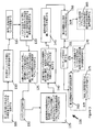
その縦軸(X)に沿って第1部分(24)と第2部分(26)を定める外面(22)を有するシャフト(20)を提供するステップ(105)と、
前記シャフト(20)の前記第2部分(26)における前記シャフト(20)を囲む少なくとも1つの溝(30)を提供するステップ(110)と、
内面(37)を有する磁気構造(35)であって、該構造(35)の前記内径が前記第1部分(24)に沿って前記シャフト(20)の前記外面(22)を囲むサイズに設定されることにより第1の径方向間隙(40)を形成する磁気構造(35)を提供するステップ(120)と、
ハウジング(15)を提供するステップ(130)と、
内側リング(55)と外側リング(60)とを有する転動体ベアリング(50)であって、該内側リング(55)は、前記第2部分(26)に沿って前記シャフト(20)の前記外面(22)を囲むサイズに設定されている内径を有することにより第2の径方向間隙(65)を形成する転動体ベアリング(50)を提供するステップ(125)とを備え
前記改善された方法は、
前記転動体ベアリング(50)の前記内側リング(55)及び前記シャフト(20)の間に第2の間隙(65)を形成するステップと、
前記環状の磁気構造(35)の径方向中心が前記環状の転動体ベアリング(50)の径方向中心と同軸に位置が合わさるように、前記ハウジング(15)に対して前記磁気構造(35)と前記転動体ベアリング(50)の前記外側リング55とを連結するステップ(135)と、
前記シャフト(20)の前記溝(30)内において断面直径が前記溝(30)の深さより大きい圧縮可能リング(70)を配置するステップ(115)と、
前記圧縮可能リング(70)が前記第2の間隙(65)の部分を塞いで前記内側リング(55)に接触するように、前記転動体ベアリング(50)の前記内側リング(55)を通じて前記シャフト(20)を挿入するステップ(140)と、
前記磁気構造(35)の前記内径を通じて前記シャフト(20)を挿入するステップ(145)と、
前記第2の間隙(65)内に液体ロッキング材料(75)を加えるステップ(150)と、
前記ロッキング材料(75)を硬くするステップ(155)と、
前記磁気構造(35)と前記シャフト(20)との間でシールを設定する磁性流体(45)を前記第1の間隙(40)内に配置するステップ(160)とを備え、
前記圧縮可能リング(70)は、前記転動体ベアリング(50)及び前記磁気構造(35)と共に前記縦軸(X)に沿って前記シャフト(20)を径方向において中心に配置し、
前記ロッキング材料(75)は、前記ベアリング(50)及び前記磁気構造(35)に対する前記シャフト(20)の配置を維持するために、前記シャフト(20)及び前記前記圧縮可能リング(70)を前記転動体ベアリング(50)の前記内側リング(55)に連結することによって、前記環状磁気構造(35)及び前記転動体ベアリング(50)に対する前記シャフト(20)の径方向の配置を維持する方法(100)。 In an improved method (100) of assembling a ferrofluidic sealing device for use in equipment having rotatable parts,
Providing a shaft (20) having an outer surface (22) defining a first portion (24) and a second portion (26) along its longitudinal axis (X);
Providing (110) at least one groove (30) surrounding the shaft (20) in the second portion (26) of the shaft (20);
A magnetic structure (35) having an inner surface (37), wherein the inner diameter of the structure (35) is set to a size surrounding the outer surface (22) of the shaft (20) along the first portion (24). Providing (120) a magnetic structure (35) to thereby form a first radial gap (40);
Providing a housing (15) (130);
A rolling element bearing (50) having an inner ring (55) and an outer ring (60), the inner ring (55) along the second portion (26) the outer surface of the shaft (20). Providing a rolling element bearing (50) having an inner diameter set to a size that surrounds (22) to form a second radial gap (65), wherein the improved method comprises: ,
Forming a second gap (65) between the inner ring (55) and the shaft (20) of the rolling element bearing (50);
The magnetic structure (35) with respect to the housing (15) so that the radial center of the annular magnetic structure (35) is coaxially aligned with the radial center of the annular rolling element bearing (50). Connecting (135) the outer ring 55 of the rolling element bearing (50);
Placing a compressible ring (70) having a cross-sectional diameter greater than the depth of the groove (30) in the groove (30) of the shaft (20);
The shaft through the inner ring (55) of the rolling element bearing (50) such that the compressible ring (70) closes the second gap (65) and contacts the inner ring (55). Inserting (20) (140);
Inserting (145) the shaft (20) through the inner diameter of the magnetic structure (35);
Adding a liquid locking material (75) in the second gap (65) (150);
Stiffening the locking material (75) (155);
Placing (160) a magnetic fluid (45) in the first gap (40) that establishes a seal between the magnetic structure (35) and the shaft (20);
The compressible ring (70) arranges the shaft (20) in the radial direction along the longitudinal axis (X) together with the rolling element bearing (50) and the magnetic structure (35),
The locking material (75) causes the shaft (20) and the compressible ring (70) to move to maintain the position of the shaft (20) relative to the bearing (50) and the magnetic structure (35). A method of maintaining the radial arrangement of the shaft (20) relative to the annular magnetic structure (35) and the rolling element bearing (50) by connecting to the inner ring (55) of the rolling element bearing (50). 100).
前記ロッキング材料(75)が硬くなった後に前記取付具から前記磁性流体封止装置(10)を除去するステップ(170)とを更に備える請求項18の方法(100)。 Disposing the magnetic fluid sealing device (10) in a fixture that holds the shaft (20) and the rolling element bearing (50) in a radial arrangement while the locking material (75) is hardened ( 165),
19. The method (100) of claim 18, further comprising the step (170) of removing the ferrofluidic sealing device (10) from the fixture after the locking material (75) has hardened.
該肩部(80)の前記表面(82)は、前記シャフト(20)の前記縦軸(X)に対して垂直であり、
前記圧縮可能リング(70)と結合する肩部(80)は、前記ロッキング材料が硬くなる間に、前記転動体ベアリング(50)と共に径方向及び軸方向に配列で前記シャフト(20)を保持する請求項18の方法(100)。 In providing (105) the shaft (20), the shaft (20) has an outer surface (22) that defines the first portion (24) and the second portion (26) along its longitudinal axis (X). Further comprising a shoulder (80) that surrounds the shaft (20) and is closely formed therewith,
The surface (82) of the shoulder (80) is perpendicular to the longitudinal axis (X) of the shaft (20);
A shoulder (80) associated with the compressible ring (70) holds the shaft (20) in radial and axial alignment with the rolling element bearing (50) while the locking material is stiff. The method (100) of claim 18.
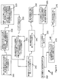
その縦軸(X)に沿って第1部分(24)と第2部分(26)を定める外面(22)を有するシャフト(20)を提供するステップ(205)と、
内面(37)を有する磁気構造(35)であって該構造(35)の内径が前記第1部分に沿って前記シャフト(20)の前記外面(22)を囲むサイズに設定されることにより第1の径方向間隙(40)を形成する磁気構造(35)を提供するステップ(220)と、
内側リング(55)と外側リング(60)とを有する転動体ベアリング(50)であって該内側リング(55)が前記第2部分(26)に沿って前記シャフト(20)の前記外面(22)を囲むサイズに設定された内径を有することにより第2の径方向間隙(65)を形成する転動体ベアリング(50)を提供するステップ(225)と、
ハウジング(15)を提供するステップ(230)とを備え、
改善された方法(200)は、
前記転動体ベアリング(50)の前記内側リング(55)及び前記シャフト(20)の間に第2の間隙(65)を形成するステップと、
前記環状の磁気構造(35)の径方向中心が、前記環状の転動体ベアリング(50)の径方向中心と同軸に位置が合わさるように、前記ハウジング(15)に対して前記磁気構造(35)と前記転動体ベアリング(50)の前記外側リング55とを連結するステップ(235)と、
前記転動体ベアリング(50)の前記内側リング(55)を通じて前記シャフト(20)を挿入するステップ(240)と、
前記磁気構造(35)の前記内径を通じて前記シャフト(20)を挿入するステップ(245)と、
前記第2の間隙(65)内に液体ロッキング材料(75)を加えるステップ(250)と、
前記シャフト(20)と前記転動体ベアリング(50)をセンタリングすると共にそれら径方向の配列で保持するために取付具内に前記磁性流体封止装置(10)を配置するステップ(265)と、
前記ロッキング材料(75)を硬くするステップ(255)と、
前記磁気構造(35)と前記シャフト(20)との間でシールを設定する磁性流体(45)を前記第1の間隙(40)内に配置するステップ(260)と、
前記ロッキング材料(75)が硬くなった後に前記取付具から前記磁性流体封止装置(10)を除去するステップ(270)とを備え、
前記環状磁気構造(35)の径方向中心及び前記環状転動体ベアリング(50)の径方向中心に対する前記シャフトの同軸の配置を維持するために、前記硬くなったロッキング材料(75)が前記シャフト(20)と前記転動体ベアリング(50)とを連結する方法(200)。 In an improved method (200) of assembling a ferrofluidic sealing device (10) for use in equipment having rotatable parts,
Providing a shaft (20) having an outer surface (22) defining a first portion (24) and a second portion (26) along its longitudinal axis (X);
A magnetic structure (35) having an inner surface (37), the inner diameter of the structure (35) being set to a size surrounding the outer surface (22) of the shaft (20) along the first portion. Providing (220) a magnetic structure (35) forming one radial gap (40);
A rolling element bearing (50) having an inner ring (55) and an outer ring (60), the inner ring (55) along the second portion (26) the outer surface (22) of the shaft (20). Providing a rolling element bearing (50) having a second radial gap (65) by having an inner diameter set to a size surrounding
Providing a housing (15) (230),
The improved method (200) is
Forming a second gap (65) between the inner ring (55) and the shaft (20) of the rolling element bearing (50);
The magnetic structure (35) with respect to the housing (15) so that the radial center of the annular magnetic structure (35) is aligned coaxially with the radial center of the annular rolling element bearing (50). And (235) connecting the outer ring 55 of the rolling element bearing (50);
Inserting (240) the shaft (20) through the inner ring (55) of the rolling element bearing (50);
Inserting (245) the shaft (20) through the inner diameter of the magnetic structure (35);
Adding a liquid locking material (75) in the second gap (65) (250);
Placing the magnetic fluid sealing device (10) in a fixture to center the shaft (20) and the rolling element bearing (50) and hold them in a radial arrangement (265);
Stiffening the locking material (75) (255);
Placing (260) a magnetic fluid (45) in the first gap (40) that establishes a seal between the magnetic structure (35) and the shaft (20);
Removing the magnetic fluid sealing device (10) from the fixture after the locking material (75) has become hard,
In order to maintain a coaxial arrangement of the shaft with respect to the radial center of the annular magnetic structure (35) and the radial center of the annular rolling element bearing (50), the hardened locking material (75) is provided with the shaft ( 20) A method (200) for connecting the rolling element bearing (50).
該肩部(80)の表面(82)は、前記シャフト(20)の前記縦軸(X)に対して垂直であり、
前記取付具と結合する前記肩部(80)は、前記ロッキング材料(75)が硬くなる間、前記転動体ベアリング(50)と共に径方向及び軸方向の配列で前記シャフト(20)を保持する請求項22の方法(200)。 In the step (205) of providing the shaft (20), the shaft (20) has an outer surface defining the first portion (24) and the second portion (26) along its longitudinal axis (X). 22), further comprising a shoulder (80) that surrounds and is intimately formed around the shaft (20),
The surface (82) of the shoulder (80) is perpendicular to the longitudinal axis (X) of the shaft (20);
The shoulder (80) coupled to the fixture holds the shaft (20) in radial and axial alignment with the rolling element bearing (50) while the locking material (75) is stiff. Item 22 (200).
Applications Claiming Priority (3)
| Application Number | Priority Date | Filing Date | Title |
|---|---|---|---|
| US10418108P | 2008-10-09 | 2008-10-09 | |
| US61/104,181 | 2008-10-09 | ||
| PCT/US2009/060000 WO2010042718A1 (en) | 2008-10-09 | 2009-10-08 | Magnetic fluid seal with centering of bearing and shaft by compressible member |
Publications (3)
| Publication Number | Publication Date |
|---|---|
| JP2012505361A JP2012505361A (en) | 2012-03-01 |
| JP2012505361A5 true JP2012505361A5 (en) | 2014-01-23 |
| JP5651596B2 JP5651596B2 (en) | 2015-01-14 |
Family
ID=41470445
Family Applications (1)
| Application Number | Title | Priority Date | Filing Date |
|---|---|---|---|
| JP2011531172A Expired - Fee Related JP5651596B2 (en) | 2008-10-09 | 2009-10-08 | Magnetic fluid sealing device centering bearing and shaft by compressible ring |
Country Status (5)
| Country | Link |
|---|---|
| US (1) | US8382118B2 (en) |
| EP (2) | EP2334940B1 (en) |
| JP (1) | JP5651596B2 (en) |
| CA (1) | CA2739789C (en) |
| WO (1) | WO2010042718A1 (en) |
Families Citing this family (14)
| Publication number | Priority date | Publication date | Assignee | Title |
|---|---|---|---|---|
| US8422193B2 (en) * | 2006-12-19 | 2013-04-16 | Axcelis Technologies, Inc. | Annulus clamping and backside gas cooled electrostatic chuck |
| US9558980B2 (en) | 2008-04-30 | 2017-01-31 | Axcelis Technologies, Inc. | Vapor compression refrigeration chuck for ion implanters |
| US9036326B2 (en) * | 2008-04-30 | 2015-05-19 | Axcelis Technologies, Inc. | Gas bearing electrostatic chuck |
| US8692215B2 (en) | 2010-05-28 | 2014-04-08 | Axcelis Technologies, Inc. | Heated rotary seal and bearing for chilled ion implantation system |
| US8481969B2 (en) * | 2010-06-04 | 2013-07-09 | Axcelis Technologies, Inc. | Effective algorithm for warming a twist axis for cold ion implantations |
| US9711324B2 (en) | 2012-05-31 | 2017-07-18 | Axcelis Technologies, Inc. | Inert atmospheric pressure pre-chill and post-heat |
| JP5913254B2 (en) * | 2013-10-30 | 2016-04-27 | グローブライド株式会社 | Fishing reel |
| JP6209096B2 (en) * | 2014-02-06 | 2017-10-04 | グローブライド株式会社 | Fishing spinning reel |
| CN105952904B (en) * | 2016-07-15 | 2019-03-29 | 湖南维格磁流体股份有限公司 | Vacuum equipment and its magnetic fluid seal driving device |
| RU2663299C1 (en) * | 2017-11-08 | 2018-08-03 | Федеральное государственное бюджетное образовательное учреждение высшего образования "Тверской государственный технический университет" | Method of producing magnetic oil |
| CN107842613B (en) | 2017-12-13 | 2019-04-02 | 广西科技大学 | A kind of arc step formula device for sealing magnetic fluid |
| CN111207217B (en) * | 2019-08-27 | 2021-10-08 | 杭州慧翔电液技术开发有限公司 | Magnetic fluid sealing device integrating high-precision rotation function |
| CN112648374B (en) * | 2020-12-30 | 2022-07-05 | 清华大学 | Soft packing sealing device |
| CN113319825B (en) * | 2021-06-10 | 2024-03-15 | 潍坊新松机器人自动化有限公司 | Intelligent robot slewer |
Family Cites Families (27)
| Publication number | Priority date | Publication date | Assignee | Title |
|---|---|---|---|---|
| GB1243234A (en) * | 1968-08-06 | 1971-08-18 | Dowding & Plummer Ltd | Improvements in or relating to shaft mountings |
| US4335885A (en) * | 1980-08-19 | 1982-06-22 | Mechanical Technology Incorporated | Plural fluid magnetic/centrifugal seal |
| CH657721A5 (en) * | 1982-01-11 | 1986-09-15 | Papst Motoren Gmbh & Co Kg | OUTDOOR RUNNER DIRECT DRIVE MOTOR. |
| US4577340A (en) * | 1983-09-19 | 1986-03-18 | Technicare Corporation | High vacuum rotating anode X-ray tube |
| JPS61137168U (en) * | 1985-02-15 | 1986-08-26 | ||
| DE3616866A1 (en) | 1986-05-20 | 1987-01-02 | Ruediger Prof Dr Ing Haberland | Self-aligning bonding process for ball bearings |
| JPS6314018U (en) * | 1986-07-11 | 1988-01-29 | ||
| US4824122A (en) * | 1987-03-02 | 1989-04-25 | Ferrofluidics Corporation | Compact magnetic fluid low pressure seal |
| JPH075325Y2 (en) * | 1988-02-13 | 1995-02-08 | 光洋精工株式会社 | Sealing device |
| US5215313A (en) * | 1990-10-24 | 1993-06-01 | Nsk, Ltd. | Magnetic fluid sealing device |
| US5235227A (en) * | 1991-01-23 | 1993-08-10 | Panavision International L.P. | Noise and vibration dampened electric motor such as for use with a sound movie camera |
| US5340122A (en) * | 1992-06-22 | 1994-08-23 | Ferrofluidics Corporation | Differentially-pumped ferrofluidic seal |
| AU4863093A (en) * | 1992-10-08 | 1994-04-21 | Ferrofluidics Corporation | Ferrofluidic seal centering ring |
| JP2729734B2 (en) * | 1992-10-12 | 1998-03-18 | 株式会社三協精機製作所 | Magnetic disk drive motor |
| US5826885A (en) * | 1996-10-02 | 1998-10-27 | Rigaku/Usa, Inc. | Magnetic fluid sealing device |
| JP3687288B2 (en) * | 1997-07-15 | 2005-08-24 | Nok株式会社 | Sealing device using magnetic fluid |
| US5975536A (en) * | 1997-09-30 | 1999-11-02 | Rigaku/Usa, Inc. | Rotary motion feedthrough with rotating magnet system |
| US6199867B1 (en) * | 1997-09-30 | 2001-03-13 | Rigaku/Usa, Inc. | Rotary motion feedthrough device |
| JP4073064B2 (en) * | 1997-12-02 | 2008-04-09 | 株式会社リガク | Magnetic field resistant magnetic fluid seal device |
| JP2000337391A (en) * | 1999-05-28 | 2000-12-05 | Minebea Co Ltd | Bearing device |
| US6857635B1 (en) * | 2001-10-18 | 2005-02-22 | Ferrotec (Usa) Corporation | Ultra high vacuum ferrofluidic seals and method of manufacture |
| US6854351B2 (en) * | 2001-11-14 | 2005-02-15 | Nsk Ltd. | Linear motion device, rolling device and separator for rolling device |
| US6558042B1 (en) * | 2001-12-28 | 2003-05-06 | Sae Magnetics(H. K.) Ltd. | Bearing guided ferrofluid seal and seal carrier |
| US7343002B1 (en) * | 2003-02-05 | 2008-03-11 | Varian Medical Systems Technologies, Inc. | Bearing assembly |
| JP4885490B2 (en) | 2005-06-30 | 2012-02-29 | 株式会社リガク | Magnetic fluid seal device |
| US7129609B1 (en) * | 2005-08-30 | 2006-10-31 | Ferrolabs, Inc. | Magneto-fluidic seal with wide working temperature range |
| JP5607978B2 (en) * | 2010-04-08 | 2014-10-15 | ミネベア株式会社 | Pivot assembly bearing |
-
2009
- 2009-10-08 EP EP09737301.3A patent/EP2334940B1/en not_active Not-in-force
- 2009-10-08 CA CA2739789A patent/CA2739789C/en not_active Expired - Fee Related
- 2009-10-08 EP EP13169115.6A patent/EP2647857A1/en not_active Withdrawn
- 2009-10-08 WO PCT/US2009/060000 patent/WO2010042718A1/en active Application Filing
- 2009-10-08 US US12/575,933 patent/US8382118B2/en active Active
- 2009-10-08 JP JP2011531172A patent/JP5651596B2/en not_active Expired - Fee Related
Similar Documents
| Publication | Publication Date | Title |
|---|---|---|
| JP2012505361A5 (en) | ||
| US10468942B2 (en) | Bearing device, conveying device, inspection device, and machine tool | |
| JP5651596B2 (en) | Magnetic fluid sealing device centering bearing and shaft by compressible ring | |
| KR102587276B1 (en) | Electrical machine and rotor for an electrical machine | |
| JP5680560B2 (en) | Rotor assembly | |
| JP6137121B2 (en) | Rotor structure and rotor manufacturing method | |
| WO2011122556A1 (en) | Fluid dynamic bearing unit and assembly method for same | |
| TWI575174B (en) | Magnetic fluid seal | |
| JP2016086611A (en) | Stator core cooling structure for rotary electric machine | |
| US20160178065A1 (en) | Mechanical seal | |
| JP2019122146A (en) | Rotary electric machine, blower, and manufacturing method for rotary electric machine | |
| US9476455B2 (en) | Outer ring for a rolling-element bearing, and method for assembling a rolling-element bearing | |
| JP2010190345A (en) | Structure and method of manufacturing rolling bearing device | |
| US10352357B2 (en) | Bearing device, conveying device, inspection device, and machine tool | |
| US8615884B2 (en) | Method of manufacturing rolling bearing device | |
| JP2012123103A (en) | Lens unit and lens fixing method | |
| JP2006158015A (en) | Method of manufacturing spindle motor | |
| KR20140070902A (en) | Shaft combination module of motor ane the manufacturing method | |
| JP2010054004A (en) | Rolling bearing unit manufacturing method, and rolling bearing unit | |
| JP5103000B2 (en) | Magnet molding method of rotor core and jig therefor | |
| JP2008253082A (en) | Motor | |
| JP4694597B2 (en) | Manufacturing method of magnetic encoder | |
| JP2016219175A (en) | Resin molded vacuum valve and manufacturing method | |
| EP2747248B1 (en) | Magnetic rotor unit | |
| KR20130009075A (en) | Hydro-dynamic bearing assembly and spindle motor having the same |