JP2012502226A - Method for estimating soot loading in diesel particulate filters, engines and aftertreatment systems - Google Patents
Method for estimating soot loading in diesel particulate filters, engines and aftertreatment systems Download PDFInfo
- Publication number
- JP2012502226A JP2012502226A JP2011526835A JP2011526835A JP2012502226A JP 2012502226 A JP2012502226 A JP 2012502226A JP 2011526835 A JP2011526835 A JP 2011526835A JP 2011526835 A JP2011526835 A JP 2011526835A JP 2012502226 A JP2012502226 A JP 2012502226A
- Authority
- JP
- Japan
- Prior art keywords
- filter
- soot load
- target
- pressure drop
- target filter
- Prior art date
- Legal status (The legal status is an assumption and is not a legal conclusion. Google has not performed a legal analysis and makes no representation as to the accuracy of the status listed.)
- Granted
Links
- 239000004071 soot Substances 0.000 title claims abstract description 72
- 238000000034 method Methods 0.000 title claims abstract description 22
- 230000008929 regeneration Effects 0.000 claims description 14
- 238000011069 regeneration method Methods 0.000 claims description 14
- 238000005259 measurement Methods 0.000 claims description 13
- 238000013459 approach Methods 0.000 claims description 2
- 230000003197 catalytic effect Effects 0.000 claims description 2
- 239000000446 fuel Substances 0.000 claims description 2
- 230000004044 response Effects 0.000 claims description 2
- 230000037303 wrinkles Effects 0.000 claims 4
- 230000000977 initiatory effect Effects 0.000 claims 1
- 238000012544 monitoring process Methods 0.000 claims 1
- 230000001172 regenerating effect Effects 0.000 claims 1
- 239000000463 material Substances 0.000 description 5
- 238000009825 accumulation Methods 0.000 description 2
- 239000003054 catalyst Substances 0.000 description 2
- 230000035699 permeability Effects 0.000 description 2
- 230000003213 activating effect Effects 0.000 description 1
- 230000008713 feedback mechanism Effects 0.000 description 1
- 238000012986 modification Methods 0.000 description 1
- 230000004048 modification Effects 0.000 description 1
- 230000003647 oxidation Effects 0.000 description 1
- 238000007254 oxidation reaction Methods 0.000 description 1
- 239000002245 particle Substances 0.000 description 1
- 238000005245 sintering Methods 0.000 description 1
- 239000000758 substrate Substances 0.000 description 1
- 238000002834 transmittance Methods 0.000 description 1
- 238000011144 upstream manufacturing Methods 0.000 description 1
Images


Classifications
-
- F—MECHANICAL ENGINEERING; LIGHTING; HEATING; WEAPONS; BLASTING
- F01—MACHINES OR ENGINES IN GENERAL; ENGINE PLANTS IN GENERAL; STEAM ENGINES
- F01N—GAS-FLOW SILENCERS OR EXHAUST APPARATUS FOR MACHINES OR ENGINES IN GENERAL; GAS-FLOW SILENCERS OR EXHAUST APPARATUS FOR INTERNAL COMBUSTION ENGINES
- F01N11/00—Monitoring or diagnostic devices for exhaust-gas treatment apparatus, e.g. for catalytic activity
- F01N11/002—Monitoring or diagnostic devices for exhaust-gas treatment apparatus, e.g. for catalytic activity the diagnostic devices measuring or estimating temperature or pressure in, or downstream of the exhaust apparatus
-
- F—MECHANICAL ENGINEERING; LIGHTING; HEATING; WEAPONS; BLASTING
- F01—MACHINES OR ENGINES IN GENERAL; ENGINE PLANTS IN GENERAL; STEAM ENGINES
- F01N—GAS-FLOW SILENCERS OR EXHAUST APPARATUS FOR MACHINES OR ENGINES IN GENERAL; GAS-FLOW SILENCERS OR EXHAUST APPARATUS FOR INTERNAL COMBUSTION ENGINES
- F01N3/00—Exhaust or silencing apparatus having means for purifying, rendering innocuous, or otherwise treating exhaust
- F01N3/02—Exhaust or silencing apparatus having means for purifying, rendering innocuous, or otherwise treating exhaust for cooling, or for removing solid constituents of, exhaust
- F01N3/021—Exhaust or silencing apparatus having means for purifying, rendering innocuous, or otherwise treating exhaust for cooling, or for removing solid constituents of, exhaust by means of filters
- F01N3/023—Exhaust or silencing apparatus having means for purifying, rendering innocuous, or otherwise treating exhaust for cooling, or for removing solid constituents of, exhaust by means of filters using means for regenerating the filters, e.g. by burning trapped particles
- F01N3/025—Exhaust or silencing apparatus having means for purifying, rendering innocuous, or otherwise treating exhaust for cooling, or for removing solid constituents of, exhaust by means of filters using means for regenerating the filters, e.g. by burning trapped particles using fuel burner or by adding fuel to exhaust
-
- F—MECHANICAL ENGINEERING; LIGHTING; HEATING; WEAPONS; BLASTING
- F01—MACHINES OR ENGINES IN GENERAL; ENGINE PLANTS IN GENERAL; STEAM ENGINES
- F01N—GAS-FLOW SILENCERS OR EXHAUST APPARATUS FOR MACHINES OR ENGINES IN GENERAL; GAS-FLOW SILENCERS OR EXHAUST APPARATUS FOR INTERNAL COMBUSTION ENGINES
- F01N3/00—Exhaust or silencing apparatus having means for purifying, rendering innocuous, or otherwise treating exhaust
- F01N3/02—Exhaust or silencing apparatus having means for purifying, rendering innocuous, or otherwise treating exhaust for cooling, or for removing solid constituents of, exhaust
- F01N3/021—Exhaust or silencing apparatus having means for purifying, rendering innocuous, or otherwise treating exhaust for cooling, or for removing solid constituents of, exhaust by means of filters
- F01N3/023—Exhaust or silencing apparatus having means for purifying, rendering innocuous, or otherwise treating exhaust for cooling, or for removing solid constituents of, exhaust by means of filters using means for regenerating the filters, e.g. by burning trapped particles
- F01N3/027—Exhaust or silencing apparatus having means for purifying, rendering innocuous, or otherwise treating exhaust for cooling, or for removing solid constituents of, exhaust by means of filters using means for regenerating the filters, e.g. by burning trapped particles using electric or magnetic heating means
-
- F—MECHANICAL ENGINEERING; LIGHTING; HEATING; WEAPONS; BLASTING
- F01—MACHINES OR ENGINES IN GENERAL; ENGINE PLANTS IN GENERAL; STEAM ENGINES
- F01N—GAS-FLOW SILENCERS OR EXHAUST APPARATUS FOR MACHINES OR ENGINES IN GENERAL; GAS-FLOW SILENCERS OR EXHAUST APPARATUS FOR INTERNAL COMBUSTION ENGINES
- F01N9/00—Electrical control of exhaust gas treating apparatus
- F01N9/002—Electrical control of exhaust gas treating apparatus of filter regeneration, e.g. detection of clogging
-
- F—MECHANICAL ENGINEERING; LIGHTING; HEATING; WEAPONS; BLASTING
- F01—MACHINES OR ENGINES IN GENERAL; ENGINE PLANTS IN GENERAL; STEAM ENGINES
- F01N—GAS-FLOW SILENCERS OR EXHAUST APPARATUS FOR MACHINES OR ENGINES IN GENERAL; GAS-FLOW SILENCERS OR EXHAUST APPARATUS FOR INTERNAL COMBUSTION ENGINES
- F01N9/00—Electrical control of exhaust gas treating apparatus
- F01N9/005—Electrical control of exhaust gas treating apparatus using models instead of sensors to determine operating characteristics of exhaust systems, e.g. calculating catalyst temperature instead of measuring it directly
-
- F—MECHANICAL ENGINEERING; LIGHTING; HEATING; WEAPONS; BLASTING
- F01—MACHINES OR ENGINES IN GENERAL; ENGINE PLANTS IN GENERAL; STEAM ENGINES
- F01N—GAS-FLOW SILENCERS OR EXHAUST APPARATUS FOR MACHINES OR ENGINES IN GENERAL; GAS-FLOW SILENCERS OR EXHAUST APPARATUS FOR INTERNAL COMBUSTION ENGINES
- F01N2240/00—Combination or association of two or more different exhaust treating devices, or of at least one such device with an auxiliary device, not covered by indexing codes F01N2230/00 or F01N2250/00, one of the devices being
- F01N2240/14—Combination or association of two or more different exhaust treating devices, or of at least one such device with an auxiliary device, not covered by indexing codes F01N2230/00 or F01N2250/00, one of the devices being a fuel burner
-
- F—MECHANICAL ENGINEERING; LIGHTING; HEATING; WEAPONS; BLASTING
- F01—MACHINES OR ENGINES IN GENERAL; ENGINE PLANTS IN GENERAL; STEAM ENGINES
- F01N—GAS-FLOW SILENCERS OR EXHAUST APPARATUS FOR MACHINES OR ENGINES IN GENERAL; GAS-FLOW SILENCERS OR EXHAUST APPARATUS FOR INTERNAL COMBUSTION ENGINES
- F01N2240/00—Combination or association of two or more different exhaust treating devices, or of at least one such device with an auxiliary device, not covered by indexing codes F01N2230/00 or F01N2250/00, one of the devices being
- F01N2240/16—Combination or association of two or more different exhaust treating devices, or of at least one such device with an auxiliary device, not covered by indexing codes F01N2230/00 or F01N2250/00, one of the devices being an electric heater, i.e. a resistance heater
-
- F—MECHANICAL ENGINEERING; LIGHTING; HEATING; WEAPONS; BLASTING
- F01—MACHINES OR ENGINES IN GENERAL; ENGINE PLANTS IN GENERAL; STEAM ENGINES
- F01N—GAS-FLOW SILENCERS OR EXHAUST APPARATUS FOR MACHINES OR ENGINES IN GENERAL; GAS-FLOW SILENCERS OR EXHAUST APPARATUS FOR INTERNAL COMBUSTION ENGINES
- F01N2550/00—Monitoring or diagnosing the deterioration of exhaust systems
- F01N2550/04—Filtering activity of particulate filters
-
- F—MECHANICAL ENGINEERING; LIGHTING; HEATING; WEAPONS; BLASTING
- F01—MACHINES OR ENGINES IN GENERAL; ENGINE PLANTS IN GENERAL; STEAM ENGINES
- F01N—GAS-FLOW SILENCERS OR EXHAUST APPARATUS FOR MACHINES OR ENGINES IN GENERAL; GAS-FLOW SILENCERS OR EXHAUST APPARATUS FOR INTERNAL COMBUSTION ENGINES
- F01N2560/00—Exhaust systems with means for detecting or measuring exhaust gas components or characteristics
- F01N2560/08—Exhaust systems with means for detecting or measuring exhaust gas components or characteristics the means being a pressure sensor
-
- F—MECHANICAL ENGINEERING; LIGHTING; HEATING; WEAPONS; BLASTING
- F01—MACHINES OR ENGINES IN GENERAL; ENGINE PLANTS IN GENERAL; STEAM ENGINES
- F01N—GAS-FLOW SILENCERS OR EXHAUST APPARATUS FOR MACHINES OR ENGINES IN GENERAL; GAS-FLOW SILENCERS OR EXHAUST APPARATUS FOR INTERNAL COMBUSTION ENGINES
- F01N2560/00—Exhaust systems with means for detecting or measuring exhaust gas components or characteristics
- F01N2560/14—Exhaust systems with means for detecting or measuring exhaust gas components or characteristics having more than one sensor of one kind
-
- F—MECHANICAL ENGINEERING; LIGHTING; HEATING; WEAPONS; BLASTING
- F01—MACHINES OR ENGINES IN GENERAL; ENGINE PLANTS IN GENERAL; STEAM ENGINES
- F01N—GAS-FLOW SILENCERS OR EXHAUST APPARATUS FOR MACHINES OR ENGINES IN GENERAL; GAS-FLOW SILENCERS OR EXHAUST APPARATUS FOR INTERNAL COMBUSTION ENGINES
- F01N2900/00—Details of electrical control or of the monitoring of the exhaust gas treating apparatus
- F01N2900/04—Methods of control or diagnosing
- F01N2900/0418—Methods of control or diagnosing using integration or an accumulated value within an elapsed period
-
- F—MECHANICAL ENGINEERING; LIGHTING; HEATING; WEAPONS; BLASTING
- F01—MACHINES OR ENGINES IN GENERAL; ENGINE PLANTS IN GENERAL; STEAM ENGINES
- F01N—GAS-FLOW SILENCERS OR EXHAUST APPARATUS FOR MACHINES OR ENGINES IN GENERAL; GAS-FLOW SILENCERS OR EXHAUST APPARATUS FOR INTERNAL COMBUSTION ENGINES
- F01N2900/00—Details of electrical control or of the monitoring of the exhaust gas treating apparatus
- F01N2900/06—Parameters used for exhaust control or diagnosing
- F01N2900/16—Parameters used for exhaust control or diagnosing said parameters being related to the exhaust apparatus, e.g. particulate filter or catalyst
- F01N2900/1606—Particle filter loading or soot amount
-
- Y—GENERAL TAGGING OF NEW TECHNOLOGICAL DEVELOPMENTS; GENERAL TAGGING OF CROSS-SECTIONAL TECHNOLOGIES SPANNING OVER SEVERAL SECTIONS OF THE IPC; TECHNICAL SUBJECTS COVERED BY FORMER USPC CROSS-REFERENCE ART COLLECTIONS [XRACs] AND DIGESTS
- Y02—TECHNOLOGIES OR APPLICATIONS FOR MITIGATION OR ADAPTATION AGAINST CLIMATE CHANGE
- Y02T—CLIMATE CHANGE MITIGATION TECHNOLOGIES RELATED TO TRANSPORTATION
- Y02T10/00—Road transport of goods or passengers
- Y02T10/10—Internal combustion engine [ICE] based vehicles
- Y02T10/40—Engine management systems
Abstract
ディーゼル微粒子フィルタの煤負荷を推定する方法は、規準ディーゼル微粒子フィルタの煤負荷を推定するための煤負荷モデルを確立する段階と、前記規準フィルタと対象フィルタとの差を考慮するために前記対象フィルタの前記煤負荷モデルを調整する段階と、前記調整した煤負荷モデルを使用して前記対象フィルタの煤負荷を推定する段階とを含む。ディーゼル微粒子フィルタを備えたエンジンが設けられている。
【選択図】図1A method for estimating the soot load of a diesel particulate filter includes: establishing a soot load model for estimating the soot load of a standard diesel particulate filter; and considering the difference between the reference filter and the target filter. Adjusting the soot load model of the method and estimating the soot load of the target filter using the adjusted soot load model. An engine with a diesel particulate filter is provided.
[Selection] Figure 1
Description
本発明は、一般にディーゼル微粒子フィルタに関し、より詳細にはディーゼル微粒子フィルタにおける煤負荷を推定する方法および装置に関する。 The present invention relates generally to diesel particulate filters, and more particularly to a method and apparatus for estimating soot loading in diesel particulate filters.
ディーゼル微粒子フィルタ(DPF)システムは、多くの市場、特に大型トラック市場では一般的になってきており、当面、重要な粒子状物質排出ソリューションであり続ける可能性が高い。DPF内に蓄積した煤質量を推定する種々の方法があるが、現在では、1つの直接フィードバック機構、すなわちDPFの前後の圧力降下を測定する圧力降下(dP)センサしかない。 Diesel particulate filter (DPF) systems are becoming common in many markets, especially the heavy truck market, and are likely to remain an important particulate emissions solution for the time being. There are various ways to estimate the soot mass accumulated in the DPF, but currently there is only one direct feedback mechanism, a pressure drop (dP) sensor that measures the pressure drop across the DPF.
dP信号を使用して、通常はある一定期間にわたる多数のフィルタの観察に基づいて、DPF煤質量を相関関係またはモデルによって推定することができ、それにより「規準(nominal)」DPFと呼ばれるべきもののデータが確立される。モデル入力は、いくつかの不確定要素を有する。オフセット、ヒステリシス、温度ドリフト、時間ドリフトなどの典型的なセンサ不確定要素に加えて、モデル精度に影響を及ぼすさらに他の要素がある。そのような要素には、DPF間のばらつき、フィルタの灰負荷、煤負荷の不均一性、触媒シンタリングなどがあり、これらの要素はすべて、対象フィルタ(subject filter)の圧力降下データを規準DPF前後の圧力降下と明確に比較して、規準DPFの煤負荷に基づいて対象DPFの煤負荷を推定することを困難にする。 Using the dP signal, the DPF 煤 mass can be estimated by a correlation or model, usually based on the observation of a number of filters over a period of time, so that what should be called a “nominal” DPF Data is established. The model input has several uncertainties. In addition to typical sensor uncertainties such as offset, hysteresis, temperature drift, and time drift, there are other factors that affect model accuracy. Such factors include variations between DPFs, filter ash load, soot load non-uniformity, catalyst sintering, etc. All of these factors use subject filter pressure drop data as a reference DPF. It makes it difficult to estimate the soot load of the target DPF based on the soot load of the reference DPF compared with the pressure drop before and after clearly.
対象DPFの煤負荷を適切な精度で推定できないと、DPFが破損したり、DPFが粒子のフィルタリングを十分に行えなくなったりすることがある。対象DPFの推定煤負荷が低すぎる場合は、能動的再生操作が行なわれる前に対象DPFが煤で過負荷状態になっていることがあり、また再生操作で許容可能な煤蓄積レベルまで燃焼されていなことがある。対象DPFの推定煤負荷が高すぎる場合は、対象DPFが、過度の再生操作を受けていることがあり、これにより有効寿命が短くなる可能性がある。 If the soot load of the target DPF cannot be estimated with appropriate accuracy, the DPF may be damaged or the DPF may not be able to sufficiently filter particles. If the estimated soot load of the target DPF is too low, the target DPF may have been sooted and overloaded before the active regeneration operation is performed, and is burned to an acceptable soot accumulation level in the regeneration operation. There is something wrong. When the estimated soot load of the target DPF is too high, the target DPF may be subjected to an excessive regeneration operation, which may shorten the useful life.
DPFの煤負荷推定精度を改善する技術を提供することが望ましい。 It is desirable to provide a technique for improving the DPF load estimation accuracy.
本発明の一態様によれば、ディーゼル微粒子フィルタの煤負荷を推定する方法が、規準ディーゼル微粒子フィルタの煤負荷を推定するための煤負荷モデルを確立する段階と、規準フィルタと対象フィルタとの差を考慮するために対象フィルタの煤負荷モデルを調整する段階と、調整した煤負荷モデルを使用して対象フィルタの煤負荷を推定する段階とを含む。 According to one aspect of the present invention, a method for estimating a soot load of a diesel particulate filter establishes a soot load model for estimating a soot load of a reference diesel particulate filter, and a difference between the reference filter and a target filter. Adjusting the soot load model of the target filter to take into account, and estimating the soot load of the target filter using the adjusted soot load model.
本発明の別の態様によれば、排気後処理システムを備えたディーゼル・エンジンが、対象ディーゼル微粒子フィルタとコントローラを有し、コントローラは、規準ディーゼル微粒子フィルタの煤負荷を推定するための煤負荷モデルを含み、コントローラは、規準フィルタと対象フィルタの違いを考慮するために対象フィルタの煤負荷モデルを調整するように適応され、且つ調整した煤負荷モデルを使用して対象フィルタの煤負荷を推定するように適応される。 According to another aspect of the present invention, a diesel engine with an exhaust aftertreatment system has a target diesel particulate filter and a controller, the controller comprising a soot load model for estimating the soot load of a standard diesel particulate filter. And the controller is adapted to adjust the filter load model of the target filter to account for differences between the reference filter and the target filter, and uses the adjusted filter load model to estimate the filter load of the target filter To be adapted.
本発明の特徴と利点は、同じ数字が類似要素を示す図面と共に以下の詳細な説明を読むことによってよりよく理解される。 The features and advantages of the present invention may be better understood by reading the following detailed description in conjunction with the drawings in which like numerals indicate like elements.
図1に、本発明の一態様による排気後処理システム23を有するディーゼル・エンジン21が示される。後処理システム23は、エンジン21の下流にディーゼル微粒子フィルタ25(DPF)を含む。DPF25は、以下では、比較のために使用される規準DPFと区別するために「対象」DPFと呼ばれる。対象DPF25は、触媒フィルタでよい。
FIG. 1 illustrates a
ヒータ27が、対象DPF25の上流に提供され、エンジン21からDPFに入る排気の温度を高めて対象DPFの能動的再生を行うように適応される。対象DPF25の少なくとも1つの状態を検出するためにセンサ29が提供される。センサ29は、コントローラ31に信号を送ってヒータ27がその信号に応じて能動的再生操作を開始するように構成される。少なくとも1つの状態は、対象DPF25前後の圧力降下、エンジン21の燃料消費量、エンジンを含む車両が移動した距離、およびエンジンまたはフィルタの動作時間をうちの少なくとも1つでよい。少なくとも1つの状態は、対象フィルタ25の煤負荷の推定レベルに対応する。後処理システム23は、通常、ディーゼル酸化触媒(DOC)(図示せず)などの他の後処理装置を含む。しかしながら、DOCは、一種のヒータ27と見なされてもよく、バーナや電気ヒータなどの個別のヒータと関連して提供されてもよい。
A
コントローラ31は、コンピュータなどの任意の適切なタイプのコントローラである。コントローラ31は、規準DPFの煤負荷を推定するための煤負荷モデルを含む。モデルは、一般に、例えば様々な気圧、排気温度、動作長等の種々の動作条件下での実際のフィルタの観測に基づいて、コントローラ内にプログラムされる。コントローラ31は、規準DPFと対象DPFとの差を考慮するために対象DPF25の煤負荷モデルを調整するように適応される。また、コントローラ31は、調整した煤負荷モデルを使用して対象DPF25の煤負荷を推定するように適応される。
The
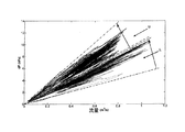
本発明の一態様によれば、規準DPFと対象DPFとの差を考慮するために対象DPF25の煤負荷モデルが調整される。例えば、図2は、2台のトラックからの2つのDPFに関する2組のdP(DPF前後の圧力降下)と体積流量(DPFを通る)測定値との関係を示す。各組は、始動から各フィルタの能動的再生までの様々な時間に取得された複数の別々の測定値を含む。
According to one aspect of the present invention, the dredged load model of the
考察のため、dPと体積流量測定値との関係の低い方の組Lは、規準DPFに関するデータを表わすと見なされ、dPと体積流量測定値との関係の高い方の組Uは、対象DPFに関するデータを表わす。しかしながら、規準DPFと対象DPFとの差は、図3に示されたように、対象DPFのdPと体積流量測定値との1組の関係が、規準フィルタのdPと体積流量測定値との1組の関係より低い場合があるようなものになる可能性があり、図3は、規準DPFのdPと体積流量との関係の範囲を、高抵抗DPFと低抵抗DPFの範囲と概略的に比較するものであることを理解されよう。図2において、組LおよびUの測定値の下にある点線は、新しいフィルタまたは能動的再生直後のフィルタのdPと体積流量との関係を近似的に示すのを支援するために提供される。 For the sake of discussion, the lower set L between dP and volumetric flow measurement is considered to represent the data for the reference DPF, and the higher set U between dP and volumetric flow measurement is the target DPF. Represents data about. However, as shown in FIG. 3, the difference between the reference DPF and the target DPF is that one set of relationship between the dP of the target DPF and the volume flow measurement value is 1 between the dP of the reference filter and the volume flow measurement value. FIG. 3 schematically compares the range of the relationship between the dP of the standard DPF and the volume flow rate with the range of the high resistance DPF and the low resistance DPF. It will be understood that In FIG. 2, the dotted lines below the measurements of sets L and U are provided to help approximate the relationship between dP and volumetric flow rate of a new filter or filter immediately after active regeneration.
本発明のいくつかの態様では、対象DPFの煤負荷モデルの調整は、対象DPFのdPと体積流量との関係を表す曲線に係数を掛けて、その曲線が規準DPFの曲線に近づくようにすることを含む。例えば、測定値Lが、規準フィルタのdPと体積流量の関係を表す場合は、測定値Uの下の点線の傾きに係数を掛けて、その傾きが、測定値Lの下の点線の傾きと等しくなるようにしてもよい。一般的に、この係数は、それぞれデグリーニングされ(de-greened)且つそれぞれ実質的に煤負荷のない規準フィルタと対象フィルタのdPと体積流量との関係を示す曲線即ちデータ点を比較することによって決定される。この状態は、通常、新しいフィルタのデグリーニング(de-greening)後の状態、または昔のフィルタの完全な能動的再生後の状態である。当然ながら、係数は、デグリーニング後の最初の始動時、能動的再生直後、またはある一定期間内を含むがそれだけではない他の時間に規準フィルタと対象フィルタのdPと体積流量との関係を示す曲線即ちデータ点を比較するような何か他の方法で決定されてもよい。 In some aspects of the invention, the adjustment of the dredging model of the target DPF involves multiplying the curve representing the relationship between the dP of the target DPF and the volume flow rate by a factor so that the curve approaches the curve of the reference DPF. Including that. For example, when the measured value L represents the relationship between the dP of the reference filter and the volume flow rate, the slope of the dotted line below the measured value U is multiplied by a coefficient, and the slope is the slope of the dotted line below the measured value L. You may make it equal. In general, this factor is determined by comparing curves or data points that show the relationship between dP and volumetric flow rate of the reference filter and the target filter, each de-greened and substantially free of dredging. It is determined. This state is usually the state after de-greening of the new filter or the state after full active regeneration of the old filter. Of course, the coefficient indicates the relationship between the dP and volume flow of the reference filter and the target filter at the first start after degleaing, immediately after active regeneration, or at other times including but not limited to a certain period of time. It may be determined in some other way such as comparing curves or data points.
対象DPF25の煤負荷は、調整された煤負荷モデルを使用することにより、コントローラ31によって推定される。本発明の一態様に従って説明すると、対象DPF25のdPと体積流量との関係を示す曲線即ちデータ点は、規準DPFの曲線即ちデータ点により近づくように係数が掛けられ、調整係数を掛けた対象フィルタのdPと体積流量測定値との関係を比較することによって、対象フィルタ25の煤負荷を推定することができる。対象フィルタの測定値に係数を掛けることによって調整されたdPと体積流量との関係を示す値における規準フィルタの煤負荷は、対象DPF25の煤負荷に対応するように推測することができる。
The soot load of the
対象DPF25の推定煤負荷が決定されたとはいえ、能動的再生サイクルは、通常、対象DPFの推定煤負荷が所定レベルを超えたときに開始される。例えば、煤負荷モデルが、煤負荷を、何らかの体積流量における規準DPF前後の圧力降下の関数として推定する場合は、対象DPF25前後の圧力降下と体積流量を監視して、特定の体積流量における少なくとも1つの圧力降下測定値を得ることができ、また特定の体積流量における少なくとも1つの圧力降下測定値の関数として対象DPFの煤負荷を推定することができる。採用される調整技術によって調整されるような圧力降下測定値が、所定値を超えた場合、コントローラ31に信号を送り、コントローラ31は信号を送って、例えばヒータ27を活動化することにより能動的再生を開始することができる。
Although the estimated soot load of the
本発明の別の態様によれば、次の式に従って時間tにおける対象DPFの煤負荷モデルの誤差(E(t))を計算することによって、対象DPF25の煤負荷を推定することができる。
According to another aspect of the present invention, the drought load of the
![]()
![]()
ここで、時間t=0,1,2,…,T
X(t)は、所定のフィルタ条件での対象DPFの煤負荷の計算値であり、
Xbarは、所定のフィルタ条件での規準DPFの煤負荷の較正値であり
Xbarは、実際の測定値または内部質量モデル予測値に基づく一定値または時間変化値でよい。
Here, time t = 0, 1, 2,..., T
X (t) is a calculated value of the dredging load of the target DPF under a predetermined filter condition,
Xbar is the calibration value of the standard DPF droop load at a given filter condition, and Xbar may be a constant value or a time-varying value based on actual measured values or internal mass model predicted values.
時間Tにおいて、次のようにオフセット値Z(t)が決定される。 At time T, the offset value Z (t) is determined as follows.
![]()
![]()
ここでGは、時間t=0から時間t=Tの間の煤負荷データの信頼性に対応する係数である。対象DPFの煤負荷の推定値Xa(t)は、次の式により決定することができる。 Here, G is a coefficient corresponding to the reliability of drought load data between time t = 0 and time t = T. The estimated value Xa (t) of the soot load of the target DPF can be determined by the following equation.
![]()
![]()
オフセット値Z(t)を加算することは、モデル誤差を最小にするためにdP煤モデルを調整する1つの単純で実際的な方法である。 Adding the offset value Z (t) is one simple and practical way to adjust the dP 煤 model to minimize model error.
当然ながら、オフセット値Z(t)を加算する他に、dP煤モデルを調整する方法はある。例えば、誤差をなくすために、下の式4で使用されるdP煤モデル・パラメータを調整するか、さらにはモデルの構造を調整してもよい。 Of course, in addition to adding the offset value Z (t), there is a method of adjusting the dP 煤 model. For example, to eliminate the error, the dPd model parameters used in Equation 4 below may be adjusted, or the model structure may be adjusted.
本発明の別の態様によれば、煤負荷モデルは、圧力降下の式に従って、規準DPF前後の圧力降下によって煤負荷を決定する。 According to another aspect of the present invention, the soot load model determines the soot load by the pressure drop around the reference DPF according to the pressure drop equation.

ここで、dPnomは、規準DPF前後の圧力降下であり
μ(T)は、温度Tでの排気ガスの粘度であり
uwallは、壁流速であり
wnom.wallは、規準DPFの壁厚であり
knom.wallは、規準DPFの透過度であり、
wsootは、煤層の厚さであり、
ksootは、煤層の透過度である。
Where dP nom is the pressure drop around the standard DPF, μ (T) is the viscosity of the exhaust gas at temperature T, u wall is the wall flow velocity, and w nom.wall is the wall thickness of the standard DPF. And k nom.wall is the transmittance of the standard DPF,
w soot is the thickness of the heel layer,
k soot is the permeability of the soot layer.
式で対象DPF内のゼロ煤負荷が正確に計算されるようにwwallとkwallのいずれかまたは両方に係数を掛けることによって、対象DPF25の煤負荷モデルを調整することができる。例えば、始動時または完全な能動的再生後、wsootがゼロまたは実質的にゼロに等しいはずであるとき、特定のμ(T)とuwallにおける対象DPF25のdPが、そのμ(T)とuwallにおける規準フィルタのdPと異なる場合は、wwallとkwallのいずれかまたは両方に調整係数を掛けて、調整されたdPが、ゼロ煤負荷における規準フィルタのdPと等しくなるようにする。
The kite load model of the
圧力降下に関する前述の式は、もっと複雑な式をできるだけ簡略にしたものである。単純化された圧力降下式は、通常、多数の変数を考慮するより複雑な式の近似である。例示のため、フィルタの少なくとも1つの特定のモデルに適用できるより複雑な圧力降下式(および非圧縮性の流れで灰堆積がゼロと仮定する)は、次の式で表すことができる。 The above formula for pressure drop is a more complex formula as simple as possible. A simplified pressure drop equation is usually an approximation of a more complex equation that takes into account many variables. For illustration purposes, a more complex pressure drop equation (and assuming zero ash accumulation in an incompressible flow) that can be applied to at least one particular model of the filter can be expressed as:
ここで、
α=チャネル幅
w=煤ケーキの厚さ
ws=基板壁の厚さ
μ=排気の粘度
Q=排気の体積流量
Vtrap=DPF体積
k=DPFの透過度性
F=28.454
L=チャネル長
ρ=排気の密度
ζ〜0.67−0.82
here,
L = channel length ρ = exhaust density ζ˜0.67−0.82
本出願では、「含む(including)」などの用語の使用は、幅広く解釈され、「含む(comprising)」のような用語と同じ意味を有し、他の構造、材料または操作の存在を排除しない。同様に、「できる(can)」や「でよい(may)」などの用語の使用は、幅広く解釈され、また構造、材料または操作が必ずしも必要ではないことを表し、これらの用語を使用しないことは、構造、材料または操作が不可欠であることを表すものではない。構造、材料または操作が不可欠であると現在考えられる限り、そのような構造、材料または操作はそのように識別される。 In this application, the use of terms such as “including” is to be interpreted broadly and has the same meaning as terms such as “comprising” and does not exclude the presence of other structures, materials or operations. . Similarly, the use of terms such as “can” and “may” is to be interpreted broadly and means that no structure, material or manipulation is necessarily required, and these terms should not be used. Does not indicate that a structure, material or operation is essential. As long as a structure, material or operation is currently considered essential, such structure, material or operation is so identified.
本発明を好ましい実施形態により図示し説明してきたが、特許請求の範囲に記載されたような発明から逸脱することなく変形と変更を行うことができることが分かる。 While the invention has been illustrated and described in terms of a preferred embodiment, it will be appreciated that variations and modifications can be effected without departing from the invention as set forth in the claims.
21 ディーゼル・エンジン
23 排気後処理システム
25 ディーゼル微粒子フィルタ(DPF)
27 ヒータ
29 センサ
31 コントローラ
21
27
Claims (20)
規準ディーゼル微粒子フィルタの煤負荷を推定するための煤負荷モデルを確立する段階と、
前記規準フィルタと対象フィルタとの差を考慮するために前記対象フィルタの前記煤負荷モデルを調整する段階と、
前記調整した煤負荷モデルを使用して前記対象フィルタの煤負荷を推定する段階とを含む方法。 A method for estimating the soot load of a diesel particulate filter,
Establishing a soot load model for estimating the soot load of a standard diesel particulate filter;
Adjusting the soot load model of the target filter to account for the difference between the reference filter and the target filter;
Estimating the soot load of the target filter using the adjusted soot load model.
E(t)=sum(X(t)-Xbar)/T
ここで、時間t=0,1,2,…,T
X(t)は、所定のフィルタ条件での前記対象フィルタの煤負荷の計算値であり、
Xbarは、前記所定のフィルタ条件での前記規準フィルタの煤負荷の較正値であり、時間Tにおいて、煤負荷の前記推定値Xa(t)を提供するために前記計算値X(t)をずらすことができるオフセット値Z(t)は、次の式によって表わされ、
Z(t)=Z(t-1)+G*[E(t-1)-Z(t-1)]
ここで、Gが、時間t=0から時間t=Tまでの煤負荷データの信頼性に対応する係数であり、前記対象フィルタの煤負荷の前記推定値Xa(t)が、式Xa(t)=X(t)−Z(t)によって表わされる、請求項1に記載の方法。 The error (E (t)) of the soot load model of the target filter at time t is
E (t) = sum (X (t) -Xbar) / T
Here, time t = 0, 1, 2,..., T
X (t) is a calculated value of the soot load of the target filter under a predetermined filter condition,
Xbar is the calibration value of the soot load of the reference filter at the predetermined filter condition, and at time T, the calculated value X (t) is shifted to provide the estimated value Xa (t) of the soot load The offset value Z (t) that can be represented by the following equation:
Z (t) = Z (t-1) + G * [E (t-1) -Z (t-1)]
Here, G is a coefficient corresponding to the reliability of the soot load data from time t = 0 to time t = T, and the estimated value Xa (t) of the soot load of the target filter is expressed by the equation Xa (t ) = X (t) -Z (t).
対象ディーゼル微粒子フィルタと、
コントローラとを有し、前記コントローラが、規準ディーゼル微粒子フィルタの煤負荷を推定するための煤負荷モデルを含み、前記コントローラが、前記規準フィルタと前記対象フィルタとの差を考慮するために前記対象フィルタの前記煤負荷モデルを調整し、前記調整した煤負荷モデルを使用して前記対象フィルタの煤負荷を推定するように適応されたディーゼル・エンジン。 A diesel engine with an exhaust aftertreatment system,
Target diesel particulate filter,
A controller, wherein the controller includes a soot load model for estimating a soot load of a standard diesel particulate filter, wherein the controller considers the difference between the reference filter and the target filter in order to take into account the difference between the target filter and the target filter A diesel engine adapted to adjust the soot load model of the engine and to estimate the soot load of the target filter using the adjusted soot load model.
Applications Claiming Priority (1)
| Application Number | Priority Date | Filing Date | Title |
|---|---|---|---|
| PCT/US2008/075752 WO2010030269A1 (en) | 2008-09-10 | 2008-09-10 | Method for estimating soot loading in a diesel particulate filter, and engine and aftertreatment system |
Publications (2)
| Publication Number | Publication Date |
|---|---|
| JP2012502226A true JP2012502226A (en) | 2012-01-26 |
| JP5702287B2 JP5702287B2 (en) | 2015-04-15 |
Family
ID=42005361
Family Applications (1)
| Application Number | Title | Priority Date | Filing Date |
|---|---|---|---|
| JP2011526835A Expired - Fee Related JP5702287B2 (en) | 2008-09-10 | 2008-09-10 | Method for estimating soot loading in diesel particulate filters, engines and aftertreatment systems |
Country Status (6)
| Country | Link |
|---|---|
| US (1) | US8646257B2 (en) |
| EP (1) | EP2321504B1 (en) |
| JP (1) | JP5702287B2 (en) |
| CN (1) | CN102149904B (en) |
| AU (1) | AU2008361679B2 (en) |
| WO (1) | WO2010030269A1 (en) |
Families Citing this family (22)
| Publication number | Priority date | Publication date | Assignee | Title |
|---|---|---|---|---|
| US8266890B2 (en) * | 2009-06-10 | 2012-09-18 | International Engine Intellectual Property Company, Llc | Preventing soot underestimation in diesel particulate filters by determining the restriction sensitivity of soot |
| DE102009049624A1 (en) * | 2009-10-16 | 2011-04-21 | Daimler Ag | Method for operating a particle filter |
| US20120102921A1 (en) * | 2010-10-28 | 2012-05-03 | Gm Global Technology Operations, Inc. | System and method for controlling regeneration of an exhaust after-treatment device |
| CN104508263B (en) * | 2012-06-21 | 2017-07-18 | 马克卡车公司 | The detection abnormal frequently method of diesel particulate filter regeneration, engine and exhaust after treatment system and warning system and method |
| CN102967467B (en) * | 2012-11-30 | 2015-11-18 | 潍柴动力股份有限公司 | A kind of durability of particle catcher evaluating method |
| US9371767B2 (en) | 2013-09-20 | 2016-06-21 | Tenneco Automotive Operating Company Inc. | Soot load determination system |
| US9352280B2 (en) * | 2014-01-24 | 2016-05-31 | GM Global Technology Operations LLC | Method of estimating hydrocarbon storage in a catalytic device |
| CN104863679B (en) * | 2015-03-31 | 2017-05-24 | 凯龙高科技股份有限公司 | DPF system carbon loading capacity estimation and blocking state judgment method |
| US10273858B2 (en) | 2015-12-02 | 2019-04-30 | Cummins Emission Solutions Inc. | Soot load estimation during idle or low load |
| MX2018010593A (en) * | 2016-03-02 | 2019-08-12 | Watlow Electric Mfg | Thermal storage device for use in a fluid flow system. |
| CN106351720B (en) * | 2016-11-30 | 2019-02-19 | 安徽江淮汽车集团股份有限公司 | A kind of method and system of the carbon accumulation amount of determining diesel particulate traps |
| WO2018135066A1 (en) * | 2017-01-17 | 2018-07-26 | 日本碍子株式会社 | Heat generation system, exhaust gas purification apparatus, and method for regenerating honeycomb structure |
| CN110005509B (en) * | 2018-01-05 | 2022-04-15 | 罗伯特·博世有限公司 | Method and system for detecting the amount of particulate matter trapped by a diesel particulate filter |
| CN111801489B (en) | 2018-03-05 | 2022-04-29 | 康明斯排放处理公司 | Improved soot load estimation using dual differential pressure sensors |
| US10774722B2 (en) * | 2018-09-04 | 2020-09-15 | Afton Chemical Corporation | Predictive methods for emissions control systems performance |
| DE102018125730A1 (en) * | 2018-10-17 | 2020-04-23 | Robert Bosch Gmbh | Method for determining the loading of a soot filter |
| DE102019206682A1 (en) | 2019-05-09 | 2020-11-12 | Robert Bosch Gmbh | Method for operating a particle filter in an exhaust gas aftertreatment system of an internal combustion engine |
| EP3808948A1 (en) * | 2019-10-16 | 2021-04-21 | Volvo Car Corporation | An improved preconditioning method for a particulate filter |
| CN113090368B (en) * | 2021-04-14 | 2022-04-26 | 潍柴动力股份有限公司 | Regeneration control method and controller for exhaust gas particulate filter, engine and vehicle |
| CN113565610B (en) * | 2021-06-29 | 2022-08-16 | 广东工业大学 | Method for judging working state of diesel vehicle particle catcher |
| CN113530656B (en) * | 2021-09-07 | 2023-01-24 | 潍柴动力股份有限公司 | DPF fault monitoring method and device |
| CN116291830B (en) * | 2023-04-17 | 2023-08-18 | 潍柴动力股份有限公司 | DPF differential pressure value correction method, DPF carbon loading correction method and vehicle |
Citations (3)
| Publication number | Priority date | Publication date | Assignee | Title |
|---|---|---|---|---|
| JPH0742537A (en) * | 1993-05-21 | 1995-02-10 | Nippondenso Co Ltd | Exhaust emission control device for diesel engine |
| JP2008101603A (en) * | 2006-10-17 | 2008-05-01 | Ibiden Co Ltd | Exhaust emission control device |
| WO2008059166A1 (en) * | 2006-11-17 | 2008-05-22 | Saint-Gobain Centre De Recherches Et D'etudes Europeen | Method for the calibration and management of an exhaust line comprising a particle filter |
Family Cites Families (18)
| Publication number | Priority date | Publication date | Assignee | Title |
|---|---|---|---|---|
| FR2799504B1 (en) * | 1999-10-08 | 2002-01-18 | Renault | METHOD AND DIAGNOSIS OF A COMBUSTION ENGINE EXHAUST SYSTEM |
| FR2829798B1 (en) * | 2001-09-14 | 2004-01-23 | Renault | METHOD FOR MANAGING THE OPERATION OF A CATALYTIC PHASE COATED PARTICLE FILTER FOR A COMBUSTION ENGINE |
| DE10145794A1 (en) | 2001-09-17 | 2003-04-03 | Fleissner Maschf Gmbh Co | Device for the continuous washing of dirty, fatty wool |
| ITTO20020072A1 (en) | 2002-01-25 | 2003-07-25 | Fiat Ricerche | METHOD FOR DETERMINING THE QUANTITY OF PARTICULATE ACCUMULATED IN A FILTER BY PARTICULATE. |
| JP4042476B2 (en) | 2002-06-14 | 2008-02-06 | 株式会社デンソー | Exhaust gas purification device for internal combustion engine |
| US6829890B2 (en) * | 2002-08-13 | 2004-12-14 | International Engine Intellectual Property Company, Llc | Forced regeneration of a diesel particulate filter |
| ITTO20030999A1 (en) * | 2003-12-12 | 2005-06-13 | Fiat Ricerche | METHOD OF ACTIVATION OF THE REGENERATION OF A PARTICULATE FILTER ACCORDING TO AN ESTIMATE OF THE QUANTITY OF THE PARTICULATE ACCUMULATED IN THE FILTER OF THE PARTICULATE. |
| JP4038187B2 (en) | 2004-03-11 | 2008-01-23 | トヨタ自動車株式会社 | Particulate matter regeneration control device for internal combustion engine exhaust purification device |
| JP4424040B2 (en) | 2004-04-05 | 2010-03-03 | 株式会社デンソー | Exhaust gas purification device for internal combustion engine |
| JP4470593B2 (en) | 2004-06-03 | 2010-06-02 | 株式会社デンソー | Exhaust gas purification device for internal combustion engine |
| WO2006055992A2 (en) | 2004-11-25 | 2006-06-01 | Avl List Gmbh | Process for determining particle emission in the exhaust gas flow from an internal combustion engine |
| US7478527B2 (en) | 2005-09-15 | 2009-01-20 | Cummins, Inc | Apparatus, system, and method for estimating particulate production |
| US7484357B2 (en) * | 2005-09-15 | 2009-02-03 | Cummins, Inc | Apparatus, system, and method for determining and implementing estimate reliability |
| US7500358B2 (en) * | 2006-08-11 | 2009-03-10 | Fleetguard, Inc | Apparatus, system, and method for enhancing soot filter protection |
| JP2008059166A (en) | 2006-08-30 | 2008-03-13 | Omron Corp | Passage ticket renewal system, renewal device, and management server |
| EP2066880A1 (en) | 2006-09-19 | 2009-06-10 | Industriell Plåtproduktion Ab | Exhaust gas system |
| US7758676B2 (en) | 2006-10-03 | 2010-07-20 | Gm Global Technology Operations, Inc. | Adaptive learning method for clean particulate filter pressure drop |
| US8171726B2 (en) | 2006-12-22 | 2012-05-08 | Cummins Inc. | Software, methods and systems including soot loading metrics |
-
2008
- 2008-09-10 EP EP08821781.5A patent/EP2321504B1/en active Active
- 2008-09-10 WO PCT/US2008/075752 patent/WO2010030269A1/en active Application Filing
- 2008-09-10 AU AU2008361679A patent/AU2008361679B2/en not_active Ceased
- 2008-09-10 CN CN200880131088.3A patent/CN102149904B/en active Active
- 2008-09-10 US US13/062,620 patent/US8646257B2/en active Active
- 2008-09-10 JP JP2011526835A patent/JP5702287B2/en not_active Expired - Fee Related
Patent Citations (4)
| Publication number | Priority date | Publication date | Assignee | Title |
|---|---|---|---|---|
| JPH0742537A (en) * | 1993-05-21 | 1995-02-10 | Nippondenso Co Ltd | Exhaust emission control device for diesel engine |
| JP2008101603A (en) * | 2006-10-17 | 2008-05-01 | Ibiden Co Ltd | Exhaust emission control device |
| WO2008059166A1 (en) * | 2006-11-17 | 2008-05-22 | Saint-Gobain Centre De Recherches Et D'etudes Europeen | Method for the calibration and management of an exhaust line comprising a particle filter |
| JP2010510427A (en) * | 2006-11-17 | 2010-04-02 | サン−ゴバン サントル ドゥ ルシェルシェ エ デトゥードゥ ユーロペン | Method for calibrating and managing an exhaust line with a particulate filter |
Also Published As
| Publication number | Publication date |
|---|---|
| EP2321504B1 (en) | 2018-11-07 |
| CN102149904A (en) | 2011-08-10 |
| US8646257B2 (en) | 2014-02-11 |
| EP2321504A1 (en) | 2011-05-18 |
| WO2010030269A1 (en) | 2010-03-18 |
| EP2321504A4 (en) | 2015-05-20 |
| US20110162352A1 (en) | 2011-07-07 |
| AU2008361679B2 (en) | 2014-06-05 |
| JP5702287B2 (en) | 2015-04-15 |
| AU2008361679A1 (en) | 2010-03-18 |
| CN102149904B (en) | 2014-01-29 |
Similar Documents
| Publication | Publication Date | Title |
|---|---|---|
| JP5702287B2 (en) | Method for estimating soot loading in diesel particulate filters, engines and aftertreatment systems | |
| JP5102873B2 (en) | Method and apparatus for maintaining a diesel exhaust particulate filter in a diesel engine exhaust system | |
| KR100605836B1 (en) | Filter control device | |
| JP5292199B2 (en) | Method for calculating the amount of particulate accumulated in the particulate filter | |
| JP6325532B2 (en) | Method, engine, exhaust aftertreatment system, warning system, and method for detecting abnormally frequent diesel particulate filter regeneration | |
| JP5833864B2 (en) | Exhaust gas treatment method and exhaust gas treatment control system for internal combustion engine | |
| CN112161743B (en) | Method for evaluating credibility of measured value of DPF (diesel particulate filter) differential pressure sensor and diesel engine | |
| US20110072789A1 (en) | Particulate matter sensor and exhaust gas purification apparatus | |
| CN105089757B (en) | Method and device for detecting soot and ash loads of a particle filter | |
| JP6197377B2 (en) | Exhaust purification device | |
| CN111058927B (en) | Method for determining the loading of a soot filter | |
| JP2008101606A (en) | Particulate detection sensor | |
| JP2008101603A (en) | Exhaust emission control device | |
| CN112761766B (en) | DPF carbon loading capacity estimation method and system | |
| JP2010116857A (en) | Abnormality diagnosing device for air flow sensor and abnormality diagnosing method therefor | |
| US9140169B2 (en) | Method for controlling regeneration within an after-treatment component of a compression-ignition engine | |
| CN110107386B (en) | Method for determining the amount of metal powder accumulated in a particulate filter suitable for an internal combustion engine | |
| JP2009024635A (en) | Exhaust emission control device of internal combustion engine and method for estimating accumulation of exhaust emission particulate in internal combustion engine | |
| JP2009108809A (en) | Exhaust emission control device and exhaust emission control method | |
| JP5493268B2 (en) | Exhaust gas purification system control method and exhaust gas purification system | |
| JP2006316727A (en) | Particulate deposit quantity calculating device | |
| JP6035830B2 (en) | DPF regeneration method | |
| JP5464151B2 (en) | Engine exhaust purification system | |
| CN102454461B (en) | For determining the method for the filter efficiency of the particulate filter in motor vehicle exhaust system | |
| JP6024379B2 (en) | Exhaust purification device |
Legal Events
| Date | Code | Title | Description |
|---|---|---|---|
| A977 | Report on retrieval |
Free format text: JAPANESE INTERMEDIATE CODE: A971007 Effective date: 20120925 |
|
| A131 | Notification of reasons for refusal |
Free format text: JAPANESE INTERMEDIATE CODE: A131 Effective date: 20121002 |
|
| A601 | Written request for extension of time |
Free format text: JAPANESE INTERMEDIATE CODE: A601 Effective date: 20121226 |
|
| A602 | Written permission of extension of time |
Free format text: JAPANESE INTERMEDIATE CODE: A602 Effective date: 20130108 |
|
| A601 | Written request for extension of time |
Free format text: JAPANESE INTERMEDIATE CODE: A601 Effective date: 20130201 |
|
| A602 | Written permission of extension of time |
Free format text: JAPANESE INTERMEDIATE CODE: A602 Effective date: 20130208 |
|
| A521 | Request for written amendment filed |
Free format text: JAPANESE INTERMEDIATE CODE: A523 Effective date: 20130304 |
|
| A02 | Decision of refusal |
Free format text: JAPANESE INTERMEDIATE CODE: A02 Effective date: 20130820 |
|
| A521 | Request for written amendment filed |
Free format text: JAPANESE INTERMEDIATE CODE: A523 Effective date: 20131219 |
|
| A521 | Request for written amendment filed |
Free format text: JAPANESE INTERMEDIATE CODE: A821 Effective date: 20131219 |
|
| A911 | Transfer to examiner for re-examination before appeal (zenchi) |
Free format text: JAPANESE INTERMEDIATE CODE: A911 Effective date: 20140121 |
|
| A912 | Re-examination (zenchi) completed and case transferred to appeal board |
Free format text: JAPANESE INTERMEDIATE CODE: A912 Effective date: 20140314 |
|
| A521 | Request for written amendment filed |
Free format text: JAPANESE INTERMEDIATE CODE: A523 Effective date: 20141117 |
|
| RD04 | Notification of resignation of power of attorney |
Free format text: JAPANESE INTERMEDIATE CODE: A7424 Effective date: 20150121 |
|
| A61 | First payment of annual fees (during grant procedure) |
Free format text: JAPANESE INTERMEDIATE CODE: A61 Effective date: 20150219 |
|
| R150 | Certificate of patent or registration of utility model |
Ref document number: 5702287 Country of ref document: JP Free format text: JAPANESE INTERMEDIATE CODE: R150 |
|
| R250 | Receipt of annual fees |
Free format text: JAPANESE INTERMEDIATE CODE: R250 |
|
| R250 | Receipt of annual fees |
Free format text: JAPANESE INTERMEDIATE CODE: R250 |
|
| R250 | Receipt of annual fees |
Free format text: JAPANESE INTERMEDIATE CODE: R250 |
|
| R250 | Receipt of annual fees |
Free format text: JAPANESE INTERMEDIATE CODE: R250 |
|
| R250 | Receipt of annual fees |
Free format text: JAPANESE INTERMEDIATE CODE: R250 |
|
| LAPS | Cancellation because of no payment of annual fees |