JP2012501469A - Optical fiber branch assembly with cable management features - Google Patents
Optical fiber branch assembly with cable management features Download PDFInfo
- Publication number
- JP2012501469A JP2012501469A JP2011524967A JP2011524967A JP2012501469A JP 2012501469 A JP2012501469 A JP 2012501469A JP 2011524967 A JP2011524967 A JP 2011524967A JP 2011524967 A JP2011524967 A JP 2011524967A JP 2012501469 A JP2012501469 A JP 2012501469A
- Authority
- JP
- Japan
- Prior art keywords
- branch
- branch body
- optical fiber
- fiber optic
- offset structure
- Prior art date
- Legal status (The legal status is an assumption and is not a legal conclusion. Google has not performed a legal analysis and makes no representation as to the accuracy of the status listed.)
- Pending
Links
Images


Classifications
-
- G—PHYSICS
- G02—OPTICS
- G02B—OPTICAL ELEMENTS, SYSTEMS OR APPARATUS
- G02B6/00—Light guides; Structural details of arrangements comprising light guides and other optical elements, e.g. couplings
- G02B6/44—Mechanical structures for providing tensile strength and external protection for fibres, e.g. optical transmission cables
- G02B6/4439—Auxiliary devices
- G02B6/4471—Terminating devices ; Cable clamps
Abstract
光ファイバケーブル、分岐本体及び1つ又は2つ以上の分岐レッグを有する光ファイバケーブル組立体が明細書において開示される。明細書において開示される実施形態では、分岐本体は、第1の端部及び第1の端部と反対側の第2の端部を有し、第1の端部からは光が延び、第2の端部からは1つ又は2つ以上の分岐レッグが延びている。分岐本体は、光ファイバインターコネクションを行う際に用いられるケーブル配線コンポーネントを支持することによってケーブルマネジメントを容易にする1つ又は2つ以上の特徴部を有するのが良い。光ファイバケーブル組立体のケーブルマネジメントコンポーネントは、有利には、垂れ下がりを阻止し、光ファイバインターコネクション部へのアクセスを容易にすると共に/或いは光ファイバインターコネクション部相互間の空気流路を改善する。 Disclosed herein is a fiber optic cable assembly having a fiber optic cable, a branch body, and one or more branch legs. In embodiments disclosed herein, the branch body has a first end and a second end opposite the first end, from which light extends, One or more branch legs extend from the two ends. The branch body may have one or more features that facilitate cable management by supporting cabling components used in making fiber optic interconnections. The cable management component of the fiber optic cable assembly advantageously prevents sagging, facilitates access to the fiber optic interconnections and / or improves the air flow path between the fiber optic interconnections.
Description
本発明の技術内容は、光ファイバケーブルマネジメントに関する。特に、本発明は、光ファイバケーブルマネジメントのための光ファイバケーブル組立体に関する。 The technical content of the present invention relates to optical fiber cable management. In particular, the present invention relates to a fiber optic cable assembly for fiber optic cable management.
〔関連出願の説明〕
本願は、米国特許仮出願第61/197,068号(発明の名称:High Density Date Center Hardware Assemblies, and Components)の優先権主張出願であり、この米国特許仮出願を参照により引用し、その記載内容全体を本明細書の一部とする。
[Description of related applications]
This application is a priority application of US Provisional Patent Application No. 61 / 197,068 (Title of Invention: High Density Date Center Hardware Assemblies, and Components), which is incorporated herein by reference. The entire contents are made a part of this specification.
本願は又、米国特許仮出願第61/190,538号(発明の名称:High Density Date Center Hardware Assemblies, and Components)の優先権主張出願であり、この米国特許仮出願を参照により引用し、その記載内容全体を本明細書の一部とする。 This application is also a priority application of US Provisional Patent Application No. 61 / 190,538 (Title of Invention: High Density Date Center Hardware Assemblies, and Components), which is incorporated herein by reference. The entire description is made a part of this specification.
本願は又、米国特許出願第12/394,140号(発明の名称:Fiber Optic Furcation Assembly Having Feature(s) for Cable Management)の優先権主張出願であり、この米国特許出願を参照により引用し、その記載内容全体を本明細書の一部とする。 This application is also a priority application of U.S. Patent Application No. 12 / 394,140 (Title: Fiber Optic Furcation Assembly Having Feature (s) for Cable Management), which is incorporated herein by reference, The entire description is made a part of this specification.
光ファイバの使用の利点としては、極めて広い帯域幅及び極めて低いノイズ(雑音)の動作が挙げられる。これら利点に鑑みて、光ファイバは、種々の用途にますます普及しており、このような要素としては、ブロードバンド音声、映像及びデータ伝送が挙げられるが、これには限定されない。光ファイバ通信ネットワークは、多くのインターコネクション(相互接続)点及び関連の機器、例えばデータセンタ、パッチパネル等を含む。一例を挙げると、データセンタ内のインターコネクション点は、機器ラック等内の幹線ケーブルと配線ケーブルとの間で生じる。 光ファイバネットワークに対する要求の増大により、データセンタは、ますます多く提供されると共にインターコネクション点の高い密度を支援するようアップグレードされている。密度が高いと、フロワスペース、ラックスペース及び引き回し経路等の量が少なくなる。しかしながら、高密度ケーブル配線コンポーネントの使用により多数のインターコネクションを所与のスペース又は領域内に構築することができるが、その結果として、弊害が生じる。例えば、所与のスペース又は領域内に設けられるインターコネクションの数の増大により、ケーブルの輻輳が増大すると共に光ファイバ機器及びケーブル輻輳の増大により熱の発生量の増大に起因して単位面積当たりの熱が増大する。このため、空気流を維持することは、データセンタ等を保守する上での検討事項である。さらに、密度が高いと、光ファイバケーブル組立体等のもつれを防ぐためのケーブル引き回し及びマネジメントが複雑になる。 Advantages of using optical fibers include extremely wide bandwidth and very low noise operation. In view of these advantages, optical fibers are becoming increasingly popular in a variety of applications, and such elements include, but are not limited to, broadband audio, video and data transmission. Fiber optic communication networks include many interconnection points and associated equipment such as data centers, patch panels, and the like. As an example, an interconnection point in a data center occurs between a main line cable and a distribution cable in an equipment rack or the like. With increasing demand for fiber optic networks, data centers are being offered more and more and are being upgraded to support high density of interconnection points. When the density is high, the amount of floor space, rack space, routing route, and the like is reduced. However, the use of high density cabling components allows a large number of interconnections to be built in a given space or region, but this results in adverse effects. For example, an increase in the number of interconnections provided in a given space or region increases cable congestion and increases the generation of heat due to increased fiber optic equipment and cable congestion per unit area. Heat increases. For this reason, maintaining the airflow is a consideration for maintaining a data center or the like. Further, when the density is high, cable routing and management for preventing entanglement of an optical fiber cable assembly or the like becomes complicated.
例えば、光ファイバ機器は、典型的には、ロウ(行又は縦横いずれか一方の並び)又はコラム(列又は縦横いずれか一方の並び)をなして配置された光ファイバインターコネクションを支持するよう構成されており、空気は、隣り合うロウ又はコラム相互間を流れて熱を放散させることができる。しかしながら、高密度ケーブル配線コンポーネントにより、隣り合うロウ又はコラムに垂れ下がりが生じる場合が多い。ケーブル配線コンポーネントの垂れ下がりは、空気流に潜在的に悪影響を及ぼす場合がある。というのは、垂れ下がり状態のケーブル配線コンポーネントは、光ファイバインターコネクション周りの空気流路に入り込み、空気流経路を減少させ又は遮断する場合があるからである。光ファイバインターコネクション周りにおける空気流路の減少又は遮断は、光ファイバ機器支持高密度インターコネクション内において既に増大したレベル状態にある場合のある熱の放散量を減少させる場合がある。また、垂れ下がり状態のケーブル配線コンポーネントにより、布設業者は、隣接の光ファイバコネクタのロウ又はコラムにアクセスするのが困難になり、しかもシステムを妨害する場合のあるもつれの問題が生じる場合がある。 For example, fiber optic equipment is typically configured to support fiber optic interconnections arranged in rows (rows or rows and columns) or columns (rows or rows and columns). Air can flow between adjacent rows or columns to dissipate heat. However, high density cabling components often sag adjacent rows or columns. Sagging of cabling components can potentially adversely affect airflow. This is because sagging cabling components can enter the air flow path around the fiber optic interconnection and reduce or block the air flow path. The reduction or blockage of the air flow path around the fiber optic interconnection may reduce the amount of heat dissipation that may already be at an increased level in the fiber optic equipment support high density interconnection. Also, the hanging cabling component makes it difficult for the installer to access the row or column of adjacent fiber optic connectors, and can create tangle problems that can interfere with the system.
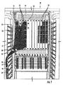
図1は、従来型光ファイバケーブル12を備えた光ファイバパッチパネル付きの例示の光ファイバ機器ラックの正面図である。図1に示されているように、光ファイバ機器ラック10は、光ファイバ接続を確立するために垂直の向きにある。具体的に説明すると、コネクタ接続型光ファイバケーブル12は、光ファイバ機器ラック10内に設置された光ファイバ機器14まで垂直に差し向けられると共に垂直ブレード16内に配置されている。各ブレード16は、垂直平面(鉛直面)を占めており、他のブレードのインターコネクションを妨害しないで単一のブレードにアクセスすることが必要な場合がある。典型的には、光ファイバケーブル12は、光ファイバ機器14に設けられているアダプタ18とのインターフェイスによりコネクタに接続される。図示のように、ストラップ20が光ファイバケーブル12の光ファイバ束22を形成してケーブルマネジメントを提供するために光ファイバケーブル12のサブセット周りに配置されている。光ファイバ束22は、光ファイバ機器ラック10の側部16にとって垂直に延びる引き回しガイド24を貫通して引き回されている。しかしながら、1つの垂直ブレード16からの光ファイバケーブル12は、図示のように隣りの垂直ブレード16相互間のスペース19のコラム中に延びると共に/或いは垂れ下がる。さらに、垂直配置方式では問題が悪化する場合がある。
FIG. 1 is a front view of an exemplary fiber optic equipment rack with fiber optic patch panels with conventional fiber
この垂れ下がり及び輻輳により、アクセス及び空気流に関する問題が生じる。図示のように、光ファイバケーブル12に(左側)は、ブレード16相互間のスペース19のコラムが塞がれるので輻輳状態を生じさせる。これにより、光ファイバケーブル12に取り付けられているコネクタ並びに光ファイバ機器14に設けられているコネクタ又はアダプタ18への指によるアクセスを可能にする上での問題が生じ、更に、空気流が絞られ、それにより発熱の問題が生じる。この結果、改良型ケーブルマネジメント特徴部を備えた光ファイバ組立体が要望されている。
This sagging and congestion creates problems with access and airflow. As shown in the figure, the optical fiber cable 12 (on the left side) is congested because the column of the space 19 between the blades 16 is blocked. This creates problems in allowing finger access to the connectors attached to the fiber
詳細な説明において開示される実施形態は、光ファイバケーブル、分岐本体及び1つ又は2つ以上の分岐レッグを有する光ファイバケーブル組立体を含む。明細書において開示される実施形態では、分岐本体は、第1の端部及び第1の端部と反対側の第2の端部を有し、第1の端部からは光が延び、第2の端部からは1つ又は2つ以上の分岐レッグが延びている。分岐本体は、光ファイバインターコネクションを行う際に用いられるケーブル配線コンポーネントを支持することによってケーブルマネジメントを容易にする1つ又は2つ以上の特徴部を有するのが良い。光ファイバケーブル組立体のこれら開示する特徴部は、有利には、光ファイバケーブル組立体が垂れ下がるのを阻止し(即ち、光ファイバケーブル組立体の支持体となり)、光ファイバインターコネクション部へのアクセスを容易にし、光ファイバインターコネクション部相互間の空気流路の閉塞を阻止又は軽減し且つ/或いは光ファイバ組立体相互間のもつれを阻止する。 The embodiments disclosed in the detailed description include a fiber optic cable assembly having a fiber optic cable, a branch body, and one or more branch legs. In embodiments disclosed herein, the branch body has a first end and a second end opposite the first end, from which light extends, One or more branch legs extend from the two ends. The branch body may have one or more features that facilitate cable management by supporting cabling components used in making fiber optic interconnections. These disclosed features of the fiber optic cable assembly advantageously prevent the fiber optic cable assembly from sagging (ie, provide support for the fiber optic cable assembly) and provide access to the fiber optic interconnection. To prevent or reduce blockage of the air flow path between the optical fiber interconnections and / or prevent entanglement between the optical fiber assemblies.
追加の特徴及び利点は、以下の詳細な説明に記載されており、一部は、この説明から当業者には容易に明らかであり、或いは、以下の詳細な説明、特許請求の範囲並びに添付の図面を含む本明細書において説明する本発明を実施することによって認識される。 Additional features and advantages are described in the following detailed description, some of which will be readily apparent to those skilled in the art from this description, or alternatively, the following detailed description, claims and appended claims It will be appreciated by practicing the invention described herein including the drawings.
上述の概要説明と以下の詳細な説明の両方は、本発明の実施形態を提供し、本発明をクレーム請求するときに本発明の性質及び特性を理解するための概観又は枠組を提供するようになっていることが解る。添付の図面は、本発明の一層の理解を可能にするために添付されており、本明細書に組み込まれてその一部をなす。図面は、本発明の種々の実施形態を記載しており、本明細書とともに、本発明の原理及び作用を説明するのに役立つ。 Both the foregoing general description and the following detailed description provide embodiments of the invention and provide an overview or framework for understanding the nature and characteristics of the invention when claiming the invention. I understand that it is. The accompanying drawings are included to provide a further understanding of the invention, and are incorporated in and constitute a part of this specification. The drawings describe various embodiments of the invention and, together with the description, serve to explain the principles and operations of the invention.
次に、本発明の好ましい実施形態を詳細に参照するが、このような実施形態の実施例が添付の図面に示されており、添付の図面には、本発明の全ての実施形態ではなく幾つかの実施形態が示されている。確かに、本発明は、多種多様な形態で実施できるので本明細書において説明する実施形態に限定されるものと解されてはならず、これとは異なり、これら実施形態は、この開示が適用される法上の要件を満たすように提供されている。同一の参照符号は、可能な限り、同一のコンポーネント又は部分を示すために用いられている。 Reference will now be made in detail to the preferred embodiments of the present invention, examples of which are illustrated in the accompanying drawings, in which several, but not all, embodiments of the present invention are illustrated. Such an embodiment is shown. Indeed, the present invention may be implemented in a wide variety of forms and should not be construed as limited to the embodiments set forth herein, and, unlike these, these embodiments apply to this disclosure. Is provided to meet legal requirements. Wherever possible, the same reference numbers will be used to designate the same components or parts.
詳細な説明において開示される実施形態は、光ファイバケーブル、分岐本体及び1つ又は2つ以上の分岐レッグを有する光ファイバケーブル組立体を含む。明細書において開示される実施形態では、分岐本体は、第1の端部及び第1の端部と反対側の第2の端部を有し、第1の端部からは光が延び、第2の端部からは1つ又は2つ以上の分岐レッグが延びている。分岐本体は、光ファイバインターコネクションを構築する場合に隣り合う光ファイバケーブル組立体のケーブル配線コンポーネントの支持を容易にする1つ又は2つ以上の支持特徴部を有するのが良い。その結果、開示する光ファイバケーブル組立体は、ケーブル配線組立体中のケーブル配線コンポーネントが垂れ下がったりもつれたりするのを軽減し又は阻止し、光ファイバインターコネクションへのアクセスを容易にすると共に/或いは光ファイバインターコネクション相互間の空気流路の閉塞を阻止し又は減少させることができるので有利である。 The embodiments disclosed in the detailed description include a fiber optic cable assembly having a fiber optic cable, a branch body, and one or more branch legs. In embodiments disclosed herein, the branch body has a first end and a second end opposite the first end, from which light extends, One or more branch legs extend from the two ends. The branch body may have one or more support features that facilitate support of the cabling components of adjacent fiber optic cable assemblies when constructing fiber optic interconnections. As a result, the disclosed fiber optic cable assembly reduces or prevents the cabling components in the cabling assembly from sagging or entangled, facilitating access to fiber optic interconnections and / or optical. Advantageously, blockage of the air flow path between the fiber interconnections can be prevented or reduced.
図2A及び図2Bは、ケーブルマネジメントのための1つ又は2つ以上の特徴部を採用した分岐本体30を有する光ファイバケーブル組立体28を示している。図示のように、分岐本体30の支持特徴部は、隣り合う光ファイバケーブル組立体28を支持して隣接のエリア中への垂れ下がり、空気流の妨害又は減少を阻止し又は軽減する。簡単に説明すると、隣り合う光ファイバケーブル組立体の光ファイバケーブル及び/又は分岐レッグは、分岐本体30によって支持される。図示のように、機器ラック34が光ファイバケーブル組立体28を受け入れてこの中に含まれ、1つ又は2つ以上の光ファイバパッチパネルを備えた光ファイバ機器32とのインターコネクション部を支持する。この例では、光ファイバ機器32は、水平に配置されたブレード36と共に水平に配置されている。光ファイバケーブル組立体28は、水平に配置されているが、光ファイバ機器32へのアクセスを可能にすると共に隣り合う光ファイバ機器32相互間の空気流路を提供するようブレード36と光ファイバ機器32との間のスペース37の水平コラムを依然として提供する。
2A and 2B illustrate a fiber
以下に詳細に説明するように、光ファイバケーブル組立体28の分岐本体80は、隣り合う光ファイバ組立体28(即ち、その分岐レッグ38及び/又は光ファイバケーブル40)が隣接のスペース37のコラム中に垂れ下がったり延びたりするのを阻止する1つ又は2つ以上の支持特徴部を有する。図2Bは、図2Aの拡大図であり、光ファイバケーブル40及び/又は隣り合う上側及び下側光ファイバケーブル組立体28A,28Bの光ファイバコネクタを有する1つ又は2つ以上の分岐レッグ38A,38Bを支持するために互いに協働的に固定された上側及び下側分岐本体38A,38Bを示している。具体的に説明すると、上側及び下側分岐本体30A,30Bは、隣り合う光ファイバケーブル組立体28A,28Bを支持し、隣接のスペース37のコラム中への垂れ下がり及びケーブル組立体のもつれを阻止するよう上側分岐本体30Aを下側分岐本体30Bに固定しやすくする1つ又は2つ以上の支持特徴部を有する。
As will be described in detail below, the branch body 80 of the fiber
図2Bに示されているように、上側分岐本体30Aは、上側光ファイバケーブル組立体28Aが下側光ファイバケーブル組立体28Bを支持できるようにする。もしそうでなければ、重力が下側光ファイバケーブル組立体28Bを隣接のスペース37のコラム中に引き込む傾向があり、それによりアクセスに悪影響を及ぼすと共に空気流を減少させる。上側光ファイバケーブル組立体28Aは、光ファイバ機器32への分岐レッグ38の接続部によって支持される。また、下側分岐本体30Bを上側分岐本体30Aに固定することにより、下側分岐本体30Bは、上側光ファイバケーブル組立体28Aを下側分岐本体30Bに向かって引っ張り、このことは、上側分岐レッグ38Aがたるみを有する場合であっても有用な場合がある。光ファイバケーブル組立体28A,28Bの分岐レッグ38A,38Bの接続部は、支持を一段と強めるよう、ぴんと引っ張られるのが良い。上側及び下側分岐本体30A,30Bによって加えられる力は、上側及び下側分岐本体30A,30Bを布設の際に、互いに取り付けた後、光ファイバケーブル組立体28A,28Bを定位置に固定するために平衡状態に達する。図示のように、分岐レッグのうちの1つ又は2つ以上は、嵌まり具合を機器に合わせて設定し、余長を貯蔵する必要性をなくすために互いに異なる長さを有するのが良いが、他の変形例では、分岐レッグは、本質的に同一である長さを有しても良い。
As shown in FIG. 2B, the
上側及び下側分岐本体30A,30Bは、構成が上側と下側で同じではなく、異なる形態で用いられるのが良い。例えば、光ファイバケーブル組立体28A,28Bが図1のように垂直に配置される場合、図2A及び図2Bに示されているように水平ではなく、分岐本体30A,30Bは、それぞれの分岐本体30が上下ではなく、左右の向きを有する状態で垂直平面(鉛直面)内に配置される。分岐本体30A,30Bは、変形例と共に以下に詳細に説明するように任意適当な設計のものであって良い。例えば、図2Bに示されているように、上側及び下側分岐本体30A,30Bは、分岐本体30A,30Bを互いに固定し又は光ファイバケーブル/分岐レッグを固定するために取り付け器具41、例えばストラップ又は他の結合具、例えばVelcro(登録商標)ストリップ又はTy-rap(登録商標)、ストリング、接着剤ストリップ及びクランプを支持する取り付け特徴部を有するのが良い。取り付け器具41及び取り付け器具41を支持し、この取り付け器具が分岐本体及び1つ又は2つ以上の光ファイバケーブル組立体を固定すると共に支持することができるようにする分岐本体に設けられる取り付け特徴部に関する詳細について以下に詳細に説明する。
The upper and
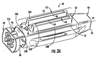
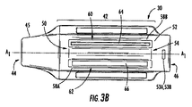
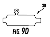
図3A及び図3Bは、それぞれ、図2A及び図2Bの上側及び下側分岐本体30A,30Bとして示された分岐本体30の第1の実施形態の詳細側面図側斜視図及び平面図である。分岐本体30は、第1の端部44及び第1の端部44と反対側の第2の端部46を備えた本体42から成っている。分岐本体30は、第1の端部44から延びる状態で分岐本体30を貫通して設けられた通路48を有し、この通路は、光ファイバケーブルを受け入れると共に第2の端部46を貫通して延びる光ファイバケーブルからの1つ又は2つ以上の分岐レッグとの分岐部を提供している。第1の端部44は、ブーツ45を有するのが良く、このブーツは、本体42に連結されると共に本体42を貫通した通路48の一部をなしており、これについては詳細に説明する。分岐本体30は、所望の任意形式の適当な材料で構成でき、このような材料としては、Ultem、Lexan、Valox等が挙げられるが、これらには限定されない。同様に、分岐本体は、任意適当な形状のものであって良い。図4に示されているように、第1の端部44は、1本又は2本以上の光ファイバを収容した光ファイバケーブル、例えば図2A及び図2Bに示されている光ファイバケーブル40を受け入れてこれを分岐するよう構成されている。光ファイバケーブル40は、任意のサイズ、構成、心線数等を有することができる。一例を挙げると、光ファイバケーブルは、任意適当な心線数の直径が例えば1.6ミリメートル、2.0ミリメートル又は2.9ミリメートルの丸形輪郭形状のものであって良い。当然のことながら、分岐本体及び/又は光ファイバケーブル組立体の他の変形例の採用が可能である。
3A and 3B are a detailed side view side perspective view and a plan view of a first embodiment of the
また、図4に示されているように、光ファイバケーブル40からの通路48の内部で分岐された1つ又は2つ以上の分岐レッグ38は、分岐本体30の第2の端部46から延びている。分岐レッグ38は、端キャップ49を貫通して延びるのが良く、この端キャップは、分岐レッグ38を分離すると共に通路48及び/又は分岐部を固定するためにこの中に施されたエポキシ、接着剤等を隠すよう本体42の第2の端部46に取り付けられている。しかしながら、他の実施形態では、端キャップを不要にすることができる。さらに、図3Aに示されているように、端キャップ49は、端キャップ49を本体42に取り付けるよう本体42の互いに反対側にそれぞれ設けられたラッチオリフィス53A,53Bと嵌合するよう構成されたラッチ51A,51B(図8A及び図8Bではラッチ51Bが見える)を有する。一例を挙げると、端キャップ49は、6つの分岐レッグ38のためのアパーチュアを有し、これらアパーチュアは、例えば2.0ミリメートルレッグ用に寸法決めされているが、任意適当なアパーチュア寸法形状又は配置状態の採用が可能である。分岐レッグ38を調製した後、これら分岐レッグをエポキシ、接着剤等が分岐本体30内に施された状態で第2の端部46内に挿入し、そしてエポキシ、接着剤等を硬化させて分岐レッグ38を分岐本体内に固定する。
Also, as shown in FIG. 4, one or
分岐本体30は、1つ又は2つ以上の隣接の光ファイバケーブル組立体28を支持するよう使用できる数個の支持特徴部を有する。設けることができる第1の支持特徴部は、図3A及び図3Bに示されているオフセット構造体50である。本明細書で用いられる「オフセット構造体」という用語は、分岐本体の表面を越えて突き出た分岐本体の一部分を意味し、この分岐本体は、これと別の分岐本体の2つを互いに隣り合わせで位置合わせすると、この別の分岐本体に設けられている類似の特徴部と協働する幾何学的形状を有する。図3A及び図3Bに示されているように、オフセット構造体50は、分岐本体30の第1の表面52を越えて延びている。オフセット構造体は、分岐本体30の長手方向軸線A1を下って長手方向に延びる第1及び第2のオフセット構造体56A,56B相互間に設けられたU字形チャネル54を有している。U字形チャネル54は、例えば図2A及び図2Bに示されているように分岐本体30に隣接して引き回された光ファイバケーブル40及び/又は分岐レッグを支持する光ファイバ引き回しガイドの少なくとも一部分を構成する。第1及び第2のオフセット構造体56A,56Bは、分岐本体30の同一側に、この実施形態では、分岐本体30の側部58A,58Bに設けられている。しかしながら、第1及び第2のオフセット構造体56A,56Bを含むオフセット構造体50は、分岐本体30の1つ又は2つ以上の側部に設けられても良く、その結果、追加の光ファイバケーブル引き回しガイドが形成されるようになる。分岐本体30のオフセット構造体50は、隣接の光ファイバケーブル組立体28を支持するよう別の分岐本体30に設けられている類似の特徴部と協働することができるようにするために、この実施形態では、第1のオフセット構造体56Aは、雌型部分62を有し、第2のオフセット部材56Bは、雄型部分60を有する。この実施形態では、雄型部分60は、第2のオフセット構造体56Bに沿って長手方向に延びる突起64の形態で設けられている。雌型部分62は、これ又第1のオフセット構造体56Aに沿って長手方向に延びるチャネル66の形態で設けられている。オフセット構造体の他の変形例では、スナップ嵌め雄型及び雌型特徴部を不要にすることができ、これらに代えて、隣り合う分岐本体を互いに保持し又は取り付ける取り付け器具、例えばVelcro(登録商標)ストラップを用いることができる。
The
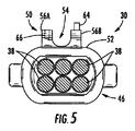
オフセット構造体50を更に示すために、図5は、分岐本体30の第2の端部46からの光ファイバケーブル組立体28の一部として分岐本体30の正面図を示している。図示のように、オフセット構造体50は、分岐本体30の第1の表面52の上に乗っている。オフセット構造体50は、分岐本体30に取り付けられる別個の構造体であっても良く、或いは、この例で提供されているように一体型金型によって形成された分岐本体30の一体部分であっても良い。通路48内に設けられた分岐レッグ38の断面も又示されている。
To further illustrate the offset
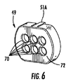
図6に示されている端キャップ49は、分岐レッグ38を受け入れてこれらを互いに広げて分岐本体30の第2の端部46の通路48を閉じてアクセスを制限すると共に/或いは通路48内に入っているエポキシ、接着剤又は他の結合材料を隠すよう使用できる。さらに、端キャップは、分岐部を分岐本体30内に位置したままにする。分岐レッグ38は各々、端キャップ49の端面72に設けられたそれぞれのオリフィス70を貫通して延びるようにする。次に、端キャップ49を分岐本体30の第2の端部46上にこれに沿って滑らせて嵌め、ラッチ51A,51B(図8A及び図8Bに示されている)を介してそれぞれラッチオリフィス53A,53B(図3A参照)に固定し又は任意他の所望の適当な仕方で固定する。第2の端部46の外寸は、端キャップ49の内寸よりも小さく、したがって、端キャップ49を分岐本体30の第2の端部46の頂部上にこれに沿って滑らせて嵌めることができるようになっているが、他の変形例の採用が可能である。エポキシ又は他の接着剤を用いて端キャップ49を第2の端部46に固定しても良く、或いは、端キャップ49を第2の端部46との張力嵌め又は摩擦嵌めにより固定しても良い。同様な仕方で、分岐本体30の第1の端部44は、例えば図10Cに示されると共にこれを参照して説明するように端部品を有しても良い。図7は、光ファイバケーブル組立体28の部分組立て図であり、光ファイバケーブル40がブーツ45を貫通して分岐本体30の通路48内に延びると共に光ファイバケーブル40内の光ファイバの分岐部73が1つ又は2つ以上の分岐レッグ38内に位置した状態を示している。
The
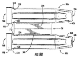
図8A及び図8Bは、それぞれ、オフセット構造体50が光ファイバケーブル組立体を支持するよう互いに連結された2つの隣り合う分岐本体30の側面図側斜視図及び平面図である。取り付け状態の分岐本体30の構造は、図2A及び図2Bに示した構造と同様である。この例では、“A”及び“B”という表示は、2つの互いに異なる分岐本体30A,30Bを表すために図8A及び図8Bの部材番号に付けられているが、注目されるべきこととして、各分岐本体30A,30Bは、この実施形態では同一の構造体であるが、このことが必要であるというわけではなく、これらオフセット構造体50A,50Bは、2つの分岐本体30A,30Bを互いに隣り合わせで位置合わせしたときに互いに協働する。
8A and 8B are a side view side perspective view and a plan view, respectively, of two
図8A及び図8Bに示されているように、2つの分岐本体30A,30Bは、これらのオフセット構造体50A,50Bが互いに連結された状態で互いに協働すると共に位置合わせされる。注目されるように、ケーブル組立体は、図面を簡単にすると共に分かりやすくするために部分的に図8A及び図8Bには示されていないが、これらの部分は、他の図では示されている。具体的に説明すると、光ファイバケーブル組立体の分岐本体にそれぞれ取り付けられた光ファイバケーブル及び分岐レッグは、図8A及び図8Bには示されていない。具体的に説明すると、オフセット構造体56A,56Bの雄型部分60A,60B(図示せず)は、オフセット構造体56A,56Bの雌型部分62B,62A中に挿入されている。分岐本体30A,30Bを図8A及び図8Bに示すように互いに位置合わせすると、各突起64A,64Bは、その対応のチャネル66B,66A(図9参照)と整列する。さらに、U字形チャネル54A,54Bの両方は、密閉通路をもたらすよう互いに位置合わせされ、この密閉通路は、少なくとも1本の光ファイバケーブル及び/又は分岐レッグを引き回すのに適した領域を形成し、包囲された光ファイバ引き回しガイド74を形成する。図2Bに示されているように、光ファイバケーブル40のうちの何本かは、光ファイバケーブル組立体28から、分岐本体30A,30Bを互いに連結したときに形成される光ファイバ引き回しガイド74中に下流側に引き回されている。これにより、ケーブルの垂れ下がりを阻止するよう引き回された光ファイバケーブル40の追加の支持体が得られる。
As shown in FIGS. 8A and 8B, the two
図9は、取り付け時の特徴を更に示すために光ファイバケーブル組立体28A,28Bを支持したときの図8A及び図8Bに示されている分岐本体30A,30Bの側面図である。図示のように、2つの光ファイバケーブル40A,40Bは、2つの分岐本体30A,30Bを互いに当接させたときに形成される光ケーブル引き回しガイド74を通って引き回される。分岐本体30A,30Bは、取り付け特徴部76A,76Bの形態をした追加のオプションとしての支持構造体を更に有し、これら取り付け特徴部76A,76Bは又、分岐本体30A,30B内に設けられ、光ファイバケーブル組立体28A,28Bを支持するのを助ける。この実施形態では、第1の取り付け特徴部76A及び第2の取り付け特徴部76Bが分岐本体30の互いに反対側に設けられている。図2A及び図2Bに示されると共に上述した取り付け器具41は、分岐本体30A,30B及びこれらのオフセット構造体56A,56Bを互いに保持するのを一段と支援すると共に1つ又は2つ以上の光ファイバケーブル組立体28のための1本又は2本以上の光ファイバケーブル40及び/又は分岐レッグの追加のケーブルマネジメント引き回しを提供するよう取り付け特徴部76A,76B中に挿入された状態で示されている。
FIG. 9 is a side view of the
換言すると、図8A、図8B及び図9は、本明細書において開示する光ファイバケーブル組立体の布設方法を示している。この方法は、第1の分岐本体30Aを備えた第1の光ファイバケーブル組立体を用意するステップを有し、1つ又は2つ以上の分岐レッグが第1の分岐本体から延びている。図示のように、第1の分岐本体30Aには、少なくとも1つの第1のオフセット構造体56Aが設けられている。同様に、この方法は、第2の分岐本体30Bを備えた第2の光ファイバケーブル組立体を用意するステップを有し、1つ又は2つ以上の分岐レッグが第2の分岐本体から延びており、第2の分岐本体には、少なくとも1つの第2のオフセット構造体56Bが設けられている。しかる後、この方法は、第1の分岐本体30Aの少なくとも1つの第1のオフセット構造体56Aを図示のように第2の分岐本体30Bの少なくとも1つの第2のオフセット構造体56Bに取り付けるステップを有する。この方法は、他のステップ、例えば、1つ又は2つ以上の分岐レッグ又はケーブルを引き回しガイド74内で引き回すステップ又は1つ又は2つ以上の取り付け器具41を例えば図9に示されている光ファイバケーブル組立体の1つ又は2つ以上の分岐本体30A,30Bの周りに配置するステップを有するのが良い。加うるに、この方法は、例えば図2A及び図2Bに示されている大きな組立体を形成するよう更に繰り返し実施されるのが良い。
In other words, FIG. 8A, FIG. 8B, and FIG. 9 show a method of laying the optical fiber cable assembly disclosed in this specification. The method includes providing a first fiber optic cable assembly having a
図10A及び図10Bは、取り付け特徴部76A,76Bに関する細部を提供している。取り付け特徴部76は、分岐本体30の第1の側部58Aに設けられた第1の取り付け特徴部76A及びその反対側の分岐本体30の第2の側部58Bに設けられた第2の取り付け特徴部76Bの形態をして分岐本体30に設けられている。第1及び第2の取り付け特徴部76A,76Bは、この例では一体形金型内で分岐本体30の状態に一体化されるが、別々の連結構造体として提供されても良い。この実施形態では、第1及び第2の取り付け特徴部76A,76Bは、分岐本体30の側部58A,58Bから分岐本体30の長手方向軸線A1に実質的に垂直な軸線に沿って延びる第1及び第2のウイング構造体80A,80Bの形態で設けられている。チャネルオリフィス82A,82Bが例えば押出し法により第1及び第2のウイング構造体80A,80Bに設けられることによってループが第1及び第2のウイング構造体80A,80Bに形成されている。このように、取り付け器具41又は他の取り付け器具は、チャネルオリフィス82A,82Bを通って引き回されて分岐本体30を一段と固定すると共に/或いは支持し、その結果、分岐本体30を一部とする光ファイバケーブル組立体28を一段と固定すると共に/或いは支持することができるようになっている。2つの分岐本体30A,30Bを一例として図9に示されているように互いに連結すると、取り付け器具41と分岐本体30との間に形成されたスペース84は、光ファイバケーブル40及び/又は分岐レッグを案内すると共に支持し、そして光ファイバケーブル40Cを一部とする光ファイバケーブル組立体28を支持するよう使用できる追加のケーブルマネジメント引き回しガイドを提供する。換言すると、光ファイバケーブル及び/又は分岐レッグの全ては、分岐本体に隣接して手際良く引き回されて垂れ下がりを阻止し、それによりブレード、モジュール等まで引き回されている光ファイバケーブル組立体の全てを補剛する。また、これにより、アクセスが向上すると共に空気流が得られ、更にケーブル組立体のもつれが阻止される。加うるに、図9に示されているように、光ファイバケーブル40Dは、取り付け器具41が取り付け特徴部76A,76Bに取り付けられた状態で分岐本体30A,30Bに当てて配置されるのが良く、その結果、光ファイバケーブル40Dは、分岐本体30A,30Bに固定された状態に保持される。取り付け特徴部76の他の変形例の採用が図9A〜図9Cに示されているように可能であり、図9A〜図9Cは、それぞれ、取り付け特徴部としてのスリップループ(即ち、ループの一方の側部は、分岐本体に取り付けられていないフラップである)、1つ又は2つ以上のフック、凹み領域及び/又は分岐本体30の一部として取り付けられ又は提供されたループの側面図である。当然のことながら、取り付け特徴部76に代えて他の特徴部の採用が可能である。さらに、取り付け器具は、取り付け特徴部を備えない状態で使用可能である。
10A and 10B provide details regarding the attachment features 76A, 76B. The
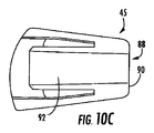
図10Cは、図8A及び図8Bと共に、光ファイバケーブル40を受け入れ、分岐本体30の第1の端部44に設けられた通路48を閉じて通路48内に入っているエポキシ又は他の結合材料へのアクセスを阻止すると共に/或いはこれを隠すために分岐本体30の第1の端部44の周りに配置可能なブーツ45を示している。光ファイバケーブル組立体28の製造中、光ファイバケーブル40を図7に示されているようにブーツ45の端面90に設けられているオリフィス88を通って延ばす。次に、ブーツ45を分岐本体30の第1の端部44上にこれに沿って滑らせて嵌めて適当な仕方で固定するのが良い。この例では、第1の端部44の外寸は、ブーツ45の内寸よりも小さく、その結果、ブーツ45を第1の端部44の頂部上にこれに沿って滑らせて嵌めることができるようになっている。ブーツは、他の変形例を有しても良く、例えば、ブーツを分岐本体中に組み込んでも良く或いはこれをなくしても良い。
FIG. 10C, in conjunction with FIGS. 8A and 8B, receives the
エポキシ又は他の接着剤を用いてブーツ45を第1の端部44に固定しても良く、或いは、これら2つ相互間の張力嵌めによりこれらを固定しても良い。ブーツ45は、ブーツ45の各側に設けられた突起構造体92を更に有し、これら突起構造体は、ブーツ45を第1の端部44の頂部に嵌めると、第1及び第2のウイング付き構造体80A,80Bの境を接して連続した他の表面を提供するよう第1及び第2のウイング付き構造体80A,80Bの後側部分94A,94B(図8A参照)上に延びる。
The
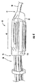
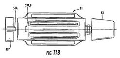
図11A〜図11Cは、分岐本体30の変形例である分岐本体81を示している。図示のように、外部フランジ85が分岐本体81の一部として設けられており、この外部フランジは、ブーツ83を受け入れるよう分岐本体81の後側部分87から延びている。外部フランジ85は、2つのラッチ89A,89Bを有し、これらラッチは、ブーツ83を分岐本体81に固定するようブーツ83に設けられているラッチオリフィス91A,91B内に嵌め込まれる。光ファイバケーブル40を第1の端部93及び通路95中に挿入し、そして外部フランジ85中に挿入して光ファイバケーブル40を分岐に備えて準備することができる。外部フランジ85は、光ファイバケーブル40を挿入するためのガイドとなり、そして、光ファイバケーブル組立体28の製造を効率的且つ好都合にすることができる。外部フランジ85は、1つ又は2つ以上の肩97を有し、肩97は、光ファイバケーブル40を外部フランジ85内に且つ分岐本体81内に固定するためのクランプ又は圧着本体となるよう使用可能である。ただし、光ファイバケーブル40を他の手段を介して外部フランジ85及び分岐本体81内に固定しても良く、このような手段としては、エポキシ又は接着剤が挙げられるが、これには限定されない。ブーツ83は、任意の種類の材料で構成可能であり、このような材料としてはUltem、Lexan(登録商標)、Valox(登録商標)、ナイロン及びサントプレンが挙げられるが、これらには限定されない。分岐本体30に関して説明した他の特徴及び変形例は、分岐本体81及び本明細書において開示する他の分岐本体に利用できる。
11A to 11C show a
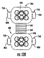
光ファイバケーブル組立体の他の実施形態及び変形例が可能である。例えば、図12A及び図12Bは、図2A〜図10Cの分岐本体に類似した別の分岐本体30を示しているが、U字形チャネル54はオフセット構造体56A,56B相互間に配置されていない。この分岐本体30は、端キャップを分岐本体30の第2の端部46上に固定するためのラッチオリフィス53A,53Bを備えていない。その代わり、端キャップ49は、摩擦嵌めにより分岐本体30に嵌まる。また、オフセット構造体50は、図12Bに示されているように別の分岐本体30Bに整列してこれに取り付けられるよう分岐本体30Aの取り付け特徴部の一部としてのオフセット構造体50のチャネル66以外のチャネルのための押出し品を備えた一中実部材として設けられる。この分岐本体30Aの他の特徴及び変形例も又上述したように可能である。
Other embodiments and variations of fiber optic cable assemblies are possible. For example, FIGS. 12A and 12B illustrate another
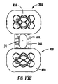
図13A及び図13Bは、分岐本体30の更に別の変形例を示している。この変形例では、取り付け特徴部76及びラッチオリフィス53A,53Bは含まれていない。オフセット構造体50は、この実施形態では分岐本体30A,30Bを互いに固定するためにのみ利用されている。U字形チャネル54が設けられているが、図12A及び図12Bの分岐本体30の変形例のように設けられなくても良い。
13A and 13B show still another modified example of the
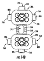
図14A及び図14Bは、分岐本体30の更に別の変形例を示している。この変形例では、底部ウイング付き構造体80Cの形態をした追加の第3の取り付け特徴部76が追加的に設けられている。ウイング付き構造体80Cは、この実施例では分岐本体30の側部58A,58Bに設けられたウイング付き構造体80A,80Bと同一の属性を有するが、これは、必要条件ではない。追加のウイング付き構造体80Cは、例えば、互いに異なる寸法のものであって良い。図14Bに示されているように、これら分岐本体30のうちの2つを位置合わせして互いに取り付けると、追加のウイング付き構造体80Cは、取り付け器具41又はウイング付き構造体80A〜80Cのチャネルオリフィス82A〜82Cを貫通して配置可能な他の取り付け器具のための追加の引き回しガイドとなるよう頂部及び底部に見える。光ファイバ組立体の更に別の実施例では、分岐本体30は、単一の取り付け特徴部を有しても良い。
14A and 14B show still another modified example of the
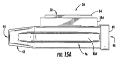
図15A及び図15Bは、分岐本体30の更に別の変形例を示している。この変形例では、取り付け特徴部76のためにウイング構造体80Aが1つしか設けられていない。図15Bに示されているように、これら分岐本体30のうちの2つを互いに位置合わせして取り付けると、ウイング付き構造体80Aは、互いに反対側に設けられる。2つのウイング付き構造体80Aは、取り付け器具41又は他の取り付け器具が2つの分岐本体30A,30Bを互いに固定すると共に図9に示されている光ファイバケーブルマネジメントと同様な光ファイバケーブルマネジメントを提供することができるのに十分な引き回しガイドとなることができる。当然のことながら、取り付け特徴部は、いずれの側に配置されても良く、任意適当な形状等を有しても良い。加うるに、分岐本体は、技術士のための標識化方式を有しても良い。
15A and 15B show still another modification of the
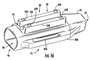
図16は、本明細書において開示する光ファイバ組立体の分岐本体30の別の変形例を示している。この変形例では、オフセット構造体50の突起64及びオリフィスチャネル66は、単一の細長い突起及びチャネルとしては設けられておらず、もっぱら、第1又は第2のオフセット構造体56A,56Bのいずれかに設けられている。もっと正確に言えば、突起64A,64B及びオリフィスチャネル66A,66Bは、図16に示されているように互いに反対側のコーナ部で第1のオフセット構造体56Aと第2のオフセット構造体56Bとの間に配置されている。このように、突起64A,64B及び協働するチャネル66A,66Bは、互いに位置合わせされて取り付けられたときに一方の分岐本体30Aの他方の分岐本体30B周りの回転防止を行なうよう互いに協働する。さらに、突起64A,64Bを提供するのに費やされる材料は少量であり、それにより、分岐本体30の製造費を減少させることができる。
FIG. 16 shows another modification of the
図17A及び図17Bは、分岐本体30の別の変形例を示しており、この分岐本体は、互いに反対側のコーナ部で第1のオフセット構造体56Aと第2のオフセット構造体56Bとの間に設けられた突起64A,64B及びチャネル66A,66Bを有している。しかしながら、この変形例では、オフセット構造体50は、図16に示されているような1つのオフセット構造体50ではなく、2つの別々のオフセット構造体50A,50Bとして設けられており、2つのU字形チャネル54A,54Bが各オフセット構造体50A,50Bに設けられている。これにより、分岐本体30中にオフセット構造体50A,50Bを提供するために用いられる材料を節約することができ、しかも、図17Aに示されているように分岐本体30の長手方向軸線A1と分岐本体30の幅方向軸線A2の両方に沿って光ファイバケーブル40を引き回す際に利用可能な追加のスペース96(図17B)が得られる。
FIG. 17A and FIG. 17B show another modification of the
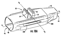
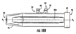
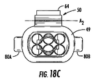
光ファイバケーブル40を分岐本体30の幅方向軸線A2に沿って分岐本体30に隣接して引き回すことが望ましい場合、オフセット構造体50を上述した実施形態から見て90°回転させてU字形チャネル54を図18A〜図18Cに示されているように幅方向軸線A2に沿って位置合わせするのが良い。さらに、所望ならばこの軸線に複数個のオフセット構造体を設けることができる。この場合も又、この特徴及び変形例の採用が可能である。
If it is desirable to route the
図19A及び図19Bは、分岐本体30の第2の端部46のための端キャップ49の別の変形例を示しており、この場合、U字形溝98がオフセット構造体50を通ってこの中に納まるよう引き回される光ファイバケーブル40のための収納チャネルとなるよう端キャップ49の上側側部99に設けられている。図19Bは、分岐本体30の第2の端部46に取り付けられる端キャップ49のこの変形例を示している。もしそうでなければ、端キャップ49の上側側部99は、U字形チャネル54によって形成されたスペースの一部分に入り込む場合があり、その結果、オフセット構造体50及びU字形チャネル54を通って引き回される光ファイバケーブル40が端キャップ49の上側側部99を横切って配置されたときに配置上の変化を生じさせることなく平らに位置することができないようになる。このようにすると、光ファイバケーブル40は、光ファイバケーブル40の曲げに起因する場合のある減衰の影響を受けにくくなる。ただし、上述した端キャップと同様な端キャップは、光ファイバケーブル40を不都合に減衰させるべきではない。
19A and 19B show another variation of the
図20A〜図20Cは、ケーブルマネジメント及び支持のために分岐本体30を有する光ファイバケーブル組立体28が提供される別の実施形態を示している。この例では、ストレージ・エリア・ネットワーク(SAN)が設けられ、この場合、光ファイバ機器100は、図2A及び図2Bに水平に提供されている場合と同様に、光ファイバ機器ラック102内の機器配線エリア(EDA)内に水平に配置されている。しかしながら、図20B及び図20Cに示されているように、分岐本体30は、互いに取り付けられてはいない。これとは異なり、分岐本体30を一部とするEDA光ファイバケーブル組立体28を支持するため、分岐本体30は、光ファイバ機器100の前部を横切って水平に延びる支持ロッド104に固定されている。具体的に説明すると、図20Cに示されているように、分岐本体30のオフセット構造体50に設けられたU字形チャネル54は、支持ロッド104を受け入れる。支持ロッド104は、支持アーム106を介して光ファイバ機器ラック102に固定的に取り付けられている。このように、光ファイバケーブル組立体28及びこれらの光ファイバケーブル40は、支持されて、隣接の空間コラム又は他の光ファイバインターコネクション中に垂れ下がるのが軽減され又は阻止される。この実施形態における分岐本体30は、互いに取り付けられていないので、突起64及びチャネル66は、オフセット構造体50に設けられる必要はない。ただし、このような構成が禁止されるわけではない。例えば、支持ロッドに取り付け可能な一形式の分岐本体並びに別の分岐本体を製造し、それにより種々の布設配備形式を増やすことが望ましい場合がある。
20A-20C illustrate another embodiment in which a fiber
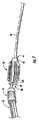
図21は、SAN光ファイバ機器100まで引き回されたEDA光ファイバケーブル組立体の部分側面図であり、SAN光ファイバ機器100は、これ又光ファイバケーブル組立体28を支持するが、図20A〜図20Cの水平配置ではなく、垂直配置状態で設けられた支持ロッド104の構造を採用している。これについては同じ技術的思想が依然として当てはまる。分岐本体30のU字形チャネル54を支持ロッド104の周りに設けてこれに固定し、それにより光ファイバケーブル組立体28及びこれらの光ファイバケーブル40が隣接のロウ中に垂れ下がるのを阻止するのが良い。上述した分岐本体30の変形例のうちのどれもが図20A〜図21の支持ロッド実施形態にも可能である。例えば、1つ又は2つ以上の取り付け特徴部76は、ケーブルマネジメント又は次の支持及び取り付け器具41を介する支持ロッド104への取り付けのために分岐本体30に依然として設けられるのが良い。
FIG. 21 is a partial side view of an EDA fiber optic cable assembly routed to the SAN
本明細書において説明した本発明の多くの変形例及び他の実施形態は、上述の説明及び関連の図面において提供されている教示の恩恵を受ける当業者に想到される。これらの改造点としては、光ファイバモジュールの数及び形式、光ファイバ機器トレーの使用、光ファイバ接続形式、光ファイバアダプタの数、実装密度等が挙げられるが、これらには限定されない。したがって、本発明は、開示した特定の実施形態には限定されず、改造例及び他の実施形態は特許請求の範囲に記載された本発明の範囲に含まれるものであることは理解されるべきである。本発明は、本発明の改造例及び変形例が特許請求の範囲に記載された本発明の範囲及びその均等範囲に属することを条件としてこのような改造例及び変形例を含むものである。特定の用語が本明細書において使用されているが、これら用語は、一般的且つ説明的な意味で用いられているに過ぎず、本発明を限定する目的で用いられているわけではない。 Many variations and other embodiments of the invention described herein will occur to those skilled in the art who would benefit from the teachings provided in the foregoing description and the associated drawings. These modifications include, but are not limited to, the number and type of optical fiber modules, the use of optical fiber equipment trays, the type of optical fiber connection, the number of optical fiber adapters, the mounting density, and the like. Therefore, it is to be understood that the invention is not limited to the specific embodiments disclosed, and that modifications and other embodiments are within the scope of the invention as set forth in the claims. It is. The present invention includes such modifications and variations as long as the modifications and variations of the present invention belong to the scope of the present invention described in the claims and equivalents thereof. Although specific terms are used herein, these terms are used in a generic and descriptive sense only and not for the purpose of limiting the invention.
Claims (15)
第1の端部及び前記第1の端部と反対側の第2の端部を有し、前記第1の端部からは前記光ファイバケーブルが延び、前記第2の端部からは前記1つ又は2つ以上の分岐レッグが延び、
前記分岐本体に設けられた少なくとも1つのオフセット構造体を有し、前記少なくとも1つのオフセット構造体は、隣接の分岐本体に設けられた少なくとも1つのオフセット構造体と協働するようになっている、
ことを特徴とする光ファイバケーブル組立体。 An optical fiber cable assembly having an optical fiber cable, a branch body, and one or more branch legs, the branch body comprising:
A first end and a second end opposite to the first end, the optical fiber cable extending from the first end, and the first end from the first end One or more branch legs extend,
Having at least one offset structure provided in the branch body, wherein the at least one offset structure is adapted to cooperate with at least one offset structure provided in an adjacent branch body;
An optical fiber cable assembly.
請求項1記載の光ファイバケーブル組立体。 Further comprising at least one attachment feature provided on the branch body;
The optical fiber cable assembly according to claim 1.
第1の端部及び前記第1の端部と反対側の第2の端部を有し、前記第1の端部からは前記光ファイバケーブルが延び、前記第2の端部からは前記1つ又は2つ以上の分岐レッグが延び、
少なくとも1つの取り付け特徴部を有し、前記取り付け特徴部は、取り付け器具を協働的に受け入れるよう構成されている、
光ファイバケーブル組立体。 An optical fiber cable assembly having an optical fiber cable, a branch body, and one or more branch legs, the branch body comprising:
A first end and a second end opposite to the first end, the optical fiber cable extending from the first end, and the first end from the first end One or more branch legs extend,
Having at least one attachment feature, the attachment feature being configured to cooperatively receive an attachment device;
Fiber optic cable assembly.
請求項3記載の光ファイバケーブル組立体。 And further comprising at least one offset structure, the at least one offset structure being adapted to cooperate with at least one offset structure provided in an adjacent branch body.
The optical fiber cable assembly according to claim 3.
請求項1、2、3又は4記載の光ファイバケーブル組立体。 An optical fiber cable routing guide provided in the branch body;
The optical fiber cable assembly according to claim 1, 2, 3, or 4.
請求項1、2、4又は5記載の光ファイバケーブル組立体。 The at least one offset structure is composed of a first offset structure and a second offset structure provided on the same side of the branch body.
The optical fiber cable assembly according to claim 1, 2, 4, or 5.
請求項1、2又は4ないし6のいずれか1項に記載の光ファイバケーブル組立体。 The at least one offset structure is composed of at least one male part and at least one female part for attaching the branch body to another branch body;
The optical fiber cable assembly according to any one of claims 1, 2, and 4 to 6.
請求項1、2又は4ないし7のいずれか1項に記載の光ファイバケーブル組立体。 The at least one offset structure cooperates with at least one offset structure provided in an adjacent branch body, thereby forming at least one region suitable for routing at least one fiber optic cable. Being
The optical fiber cable assembly according to any one of claims 1, 2, and 4 to 7.
請求項2又は4ないし7のいずれか1項に記載の光ファイバケーブル組立体。 The at least one attachment feature comprises a first attachment feature provided on a first side of the branch body and a second attachment feature provided on a second side of the branch body. Being
The optical fiber cable assembly according to claim 2 or any one of claims 4 to 7.
請求項1ないし9のいずれか1項に記載の光ファイバケーブル組立体。 Further comprising a fitting for cable routing management;
The optical fiber cable assembly according to any one of claims 1 to 9.
光ファイバパッチパネルと、
光ファイバケーブル、分岐本体、及び1つ又は2つ以上の分岐レッグを有する光ファイバケーブル組立体とを有し、前記分岐本体は、
第1の端部及び前記第1の端部と反対側の第2の端部を有し、前記第1の端部からは前記光ファイバケーブルが延び、前記第2の端部からは前記1つ又は2つ以上の分岐レッグが延び、少なくとも1つの分岐レッグは、引き回されて前記光ファイバパッチパネルに光結合され、
前記分岐本体の一側部に設けられた少なくとも1つのオフセット構造体を有し、前記少なくとも1つのオフセット構造体は、隣接の分岐本体に設けられた少なくとも1つのオフセット構造体と協働するようになっており、
前記分岐本体に設けられた少なくとも1つの取り付け特徴部を有し、
取り付け器具を有し、前記取り付け器具は、前記少なくとも1つの取り付け特徴部に係合する、
ことを特徴とする光ファイバ組立体。 An optical fiber assembly comprising:
An optical fiber patch panel;
A fiber optic cable, a branch body, and a fiber optic cable assembly having one or more branch legs, the branch body comprising:
A first end and a second end opposite to the first end, the optical fiber cable extending from the first end, and the first end from the first end One or more branch legs extend, and at least one branch leg is routed and optically coupled to the fiber optic patch panel;
At least one offset structure provided on one side of the branch body, wherein the at least one offset structure cooperates with at least one offset structure provided on an adjacent branch body; And
Having at least one attachment feature provided on the branch body;
An attachment device, wherein the attachment device engages the at least one attachment feature;
An optical fiber assembly characterized by that.
請求項11記載の光ファイバ組立体。 The branch body is fixed to an adjacent branch body;
The optical fiber assembly according to claim 11.
請求項11又は12記載の光ファイバ組立体。 And further comprising at least one optical fiber cable routing guide provided in the branch body.
The optical fiber assembly according to claim 11 or 12.
請求項11ないし13のいずれか1項に記載の光ファイバ組立体。 The mounting device fixes a plurality of optical fiber cables to the branch body for cable routing management.
The optical fiber assembly according to any one of claims 11 to 13.
第1の分岐本体を有する第1の光ファイバケーブル組立体を用意するステップであって、前記第1の分岐本体からは1つ又は2つ以上の分岐レッグが延び、前記第1の分岐本体には少なくとも1つの第1のオフセット構造体が設けられているステップと、
第2の分岐本体を有する第2の光ファイバケーブル組立体を用意するステップであって、前記第2の分岐本体からは1つ又は2つ以上の分岐レッグが延び、前記第2の分岐本体には少なくとも1つの第2のオフセット構造体が設けられているステップと、
前記第1の分岐本体の前記少なくとも1つの第1のオフセット構造体を前記第2の分岐本体の前記少なくとも1つのオフセット構造体に取り付けるステップと、を備えている、
ことを特徴とする方法。 A method of laying a fiber optic cable assembly comprising:
Preparing a first fiber optic cable assembly having a first branch body, wherein one or more branch legs extend from the first branch body, and the first branch body is connected to the first branch body. Is provided with at least one first offset structure;
Providing a second fiber optic cable assembly having a second branch body, wherein one or more branch legs extend from the second branch body, and the second branch body is connected to the second branch body. Is provided with at least one second offset structure;
Attaching the at least one first offset structure of the first branch body to the at least one offset structure of the second branch body.
A method characterized by that.
Applications Claiming Priority (7)
| Application Number | Priority Date | Filing Date | Title |
|---|---|---|---|
| US19053808P | 2008-08-29 | 2008-08-29 | |
| US61/190,538 | 2008-08-29 | ||
| US19706808P | 2008-10-23 | 2008-10-23 | |
| US61/197,068 | 2008-10-23 | ||
| US12/394,140 US7903925B2 (en) | 2008-08-29 | 2009-02-27 | Fiber optic furcation assembly having feature(s) for cable management |
| US12/394,140 | 2009-02-27 | ||
| PCT/US2009/004577 WO2010024851A2 (en) | 2008-08-29 | 2009-08-11 | Fiber optic furcation assembly having feature(s) for cable management |
Publications (2)
| Publication Number | Publication Date |
|---|---|
| JP2012501469A true JP2012501469A (en) | 2012-01-19 |
| JP2012501469A5 JP2012501469A5 (en) | 2012-09-27 |
Family
ID=41279376
Family Applications (1)
| Application Number | Title | Priority Date | Filing Date |
|---|---|---|---|
| JP2011524967A Pending JP2012501469A (en) | 2008-08-29 | 2009-08-11 | Optical fiber branch assembly with cable management features |
Country Status (9)
| Country | Link |
|---|---|
| US (1) | US7903925B2 (en) |
| EP (1) | EP2321686B1 (en) |
| JP (1) | JP2012501469A (en) |
| CN (1) | CN102165355B (en) |
| AU (1) | AU2009286122B2 (en) |
| CA (1) | CA2735500C (en) |
| ES (1) | ES2395361T3 (en) |
| PT (1) | PT2321686E (en) |
| WO (1) | WO2010024851A2 (en) |
Families Citing this family (107)
| Publication number | Priority date | Publication date | Assignee | Title |
|---|---|---|---|---|
| AU2010259068B2 (en) | 2009-06-08 | 2014-07-31 | Commscope, Inc. Of North Carolina | High density patching system for cable and optical fiber |
| CN102844725B (en) * | 2009-12-28 | 2016-03-02 | 惠普发展公司,有限责任合伙企业 | For providing the calculating of physical separation and I/O resource with the system of implementation space and power save in the data in the heart |
| WO2011097299A2 (en) * | 2010-02-02 | 2011-08-11 | Adc Telecommunications, Inc. | Fiber optic cable bundle with staggered connectors |
| US8818156B2 (en) * | 2010-03-30 | 2014-08-26 | Corning Cable Systems Llc | Multiple channel optical fiber furcation tube and cable assembly using same |
| US20110268403A1 (en) * | 2010-04-30 | 2011-11-03 | Ciechomski Tomasz A | Mounting and strain relief device |
| US8995106B2 (en) | 2011-02-08 | 2015-03-31 | Raycap, S.A. | Overvoltage protection system for wireless communication systems |
| US11251608B2 (en) | 2010-07-13 | 2022-02-15 | Raycap S.A. | Overvoltage protection system for wireless communication systems |
| JPWO2012127684A1 (en) * | 2011-03-24 | 2014-07-24 | 富士通株式会社 | Rack and cable management equipment |
| US9188747B2 (en) | 2011-05-23 | 2015-11-17 | Senko Advanced Components, Inc. | True one piece housing fiber optic adapter |
| US8958673B2 (en) | 2011-05-27 | 2015-02-17 | Corning Cable Systems Llc | Molded fiber optic cable furcation assemblies, and related fiber optic components, assemblies, and methods |
| US8630523B2 (en) | 2011-07-13 | 2014-01-14 | Corning Cable Systems Llc | Methods of preparing strength member pulling members in fiber optic cable furcations and related components, assemblies, and fiber optic cables |
| US8731364B2 (en) | 2011-11-21 | 2014-05-20 | Ortronics, Inc. | Breakout assemblies and associated mounting members for fiber optic applications |
| US20130183012A1 (en) * | 2012-01-13 | 2013-07-18 | Alma Delia Cabanne Lopez | Fan-out kit for a furcation system |
| US8948557B2 (en) | 2012-06-15 | 2015-02-03 | Andrew Llc | Universal remote radio unit fiber optic cable assembly |
| US9530544B2 (en) | 2012-11-19 | 2016-12-27 | Commscope Technologies Llc | Shielded electrical conductor furcation assembly |
| US9618718B2 (en) | 2012-06-15 | 2017-04-11 | Commscope Technologies Llc | Universal remote radio unit bird armored fiber optic cable assembly |
| US8974124B2 (en) | 2012-08-16 | 2015-03-10 | Senko Advanced Components, Inc. | Fiber optic connector |
| US20140133822A1 (en) | 2012-11-13 | 2014-05-15 | Cesar Alejandro de los Santos Campos | Rotatable furcation assembly |
| US9536640B2 (en) | 2012-11-19 | 2017-01-03 | Commscope Technologies Llc | Rugged furcation tube |
| US9235021B2 (en) | 2012-11-19 | 2016-01-12 | Commscope Technologies Llc | Optical fiber / electrical composite cable assembly with sealed breakout kit |
| US9268103B2 (en) | 2013-05-10 | 2016-02-23 | Senko Advanced Components, Inc. | Interlockable fiber optic connector adaptors |
| US9360649B2 (en) | 2013-05-22 | 2016-06-07 | Senko Advanced Components, Inc. | Cable guide for fiber optic cables |
| WO2014200999A1 (en) * | 2013-06-10 | 2014-12-18 | Afl Telecommunications Llc | Optical fiber furcation assembly and method |
| US9140872B2 (en) | 2013-09-17 | 2015-09-22 | Panduit Corp. | Hydra cable assembly and components thereof |
| US9618703B2 (en) | 2013-10-03 | 2017-04-11 | Senko Advanced Components, Inc. | Connector housing for securing an optical cable and methods of use and manufacture thereof |
| US9640986B2 (en) | 2013-10-23 | 2017-05-02 | Raycap Intellectual Property Ltd. | Cable breakout assembly |
| US9477049B2 (en) | 2013-12-20 | 2016-10-25 | Senko Advanced Components, Inc. | Lockable connectors and connection assemblies |
| US9535230B2 (en) | 2014-01-31 | 2017-01-03 | Senko Advanced Components, Inc. | Integrated fiber optic cable fan-out connector |
| US9297964B2 (en) | 2014-04-18 | 2016-03-29 | Senko Advanced Components, Inc. | Optical fiber connector assembly |
| US9274287B2 (en) | 2014-05-13 | 2016-03-01 | Senko Advanced Components, Inc. | Optical fiber connector and ferrule |
| US9618702B2 (en) | 2014-06-09 | 2017-04-11 | Senko Advanced Components, Inc. | Reduced-profile data transmission element connectors, adapters, and connection assemblies thereof |
| WO2015195829A1 (en) * | 2014-06-17 | 2015-12-23 | Afl Telecommunications Llc | Optical fiber furcation transition assembly with integrated retention feature |
| US9690065B2 (en) | 2014-09-12 | 2017-06-27 | Panduit Corp. | High density fiber enclosure and method |
| US9599778B2 (en) | 2014-10-22 | 2017-03-21 | Senko Advanced Components, Inc. | Latching connector with remote release |
| US9575277B2 (en) * | 2015-01-15 | 2017-02-21 | Raycap, S.A. | Fiber optic cable breakout assembly |
| US9494745B2 (en) | 2015-01-16 | 2016-11-15 | Senko Advanced Components, Inc. | Sealable communication cable connection assemblies |
| US9658409B2 (en) | 2015-03-03 | 2017-05-23 | Senko Advanced Components, Inc. | Optical fiber connector with changeable polarity |
| US9684139B2 (en) | 2015-05-29 | 2017-06-20 | Senko Advanced Components, Inc. | Optical fiber connector with changeable gender |
| US10802237B2 (en) | 2015-11-03 | 2020-10-13 | Raycap S.A. | Fiber optic cable management system |
| US9971119B2 (en) | 2015-11-03 | 2018-05-15 | Raycap Intellectual Property Ltd. | Modular fiber optic cable splitter |
| CA2966349C (en) | 2016-05-05 | 2024-03-19 | Belden Canada Inc. | Overmoulded assembly with strain relief |
| US9726830B1 (en) | 2016-06-28 | 2017-08-08 | Senko Advanced Components, Inc. | Connector and adapter system for two-fiber mechanical transfer type ferrule |
| US10215944B2 (en) | 2016-06-30 | 2019-02-26 | Panduit Corp. | Modular fiber optic tray |
| US10228521B2 (en) | 2016-12-05 | 2019-03-12 | Senko Advanced Components, Inc. | Narrow width adapters and connectors with modular latching arm |
| US10078188B1 (en) | 2016-12-05 | 2018-09-18 | Senko Advanced Components, Inc. | Springless push/pull fiber optic connector |
| WO2018136812A1 (en) | 2017-01-20 | 2018-07-26 | Raycap S.A. | Power transmission system for wireless communication systems |
| US10185100B2 (en) | 2017-01-30 | 2019-01-22 | Senko Advanced Components, Inc | Modular connector and adapter assembly using a removable anchor device |
| US10725248B2 (en) | 2017-01-30 | 2020-07-28 | Senko Advanced Components, Inc. | Fiber optic receptacle with integrated device therein incorporating a behind-the-wall fiber optic receptacle |
| US10191230B2 (en) | 2017-01-30 | 2019-01-29 | Senko Advanced Components, Inc. | Optical connectors with reversible polarity |
| US11333836B2 (en) | 2017-01-30 | 2022-05-17 | Senko Advanced Components, Inc. | Adapter for optical connectors |
| US10444444B2 (en) | 2017-01-30 | 2019-10-15 | Senko Advanced Components, Inc. | Remote release tab connector assembly |
| US10416394B2 (en) | 2017-01-30 | 2019-09-17 | Senko Advanced Components, Inc. | Fiber optic receptacle with integrated device therein |
| EP3602155A1 (en) | 2017-03-21 | 2020-02-05 | Corning Research & Development Corporation | Fiber optic cable assembly with thermoplastically overcoated fusion splice, and related method and apparatus |
| US20180275356A1 (en) * | 2017-03-22 | 2018-09-27 | Corning Optical Communications LLC | Optical shuffle cable, cable assembly, and methods of making the same |
| US10209461B2 (en) | 2017-04-07 | 2019-02-19 | Senko Advanced Components | Behind the wall optical connector with reduced components |
| US10754098B2 (en) | 2017-04-07 | 2020-08-25 | Senko Advanced Components, Inc. | Behind the wall optical connector with reduced components |
| US10989884B2 (en) | 2017-04-07 | 2021-04-27 | Senko Advanced Components, Inc. | Behind the wall optical connector with reduced components |
| US10359583B2 (en) | 2017-04-07 | 2019-07-23 | Senko Advanced Components, Inc. | Behind the wall optical connector with reduced components |
| US10401576B2 (en) | 2017-05-10 | 2019-09-03 | Senko Advanced Components, Inc. | MPO micro-latch-lock connector |
| US10146016B1 (en) | 2017-05-10 | 2018-12-04 | Senko Advanced Components, Inc | MPO micro-latchlock connector |
| US10295759B2 (en) | 2017-05-18 | 2019-05-21 | Senko Advanced Components, Inc. | Optical connector with forward-biasing projections |
| US10359576B2 (en) | 2017-06-15 | 2019-07-23 | Senko Advanced Components, Inc. | SC low profile connector with optional boot |
| ES2884060T3 (en) | 2017-06-28 | 2021-12-10 | Corning Res & Dev Corp | Fiber optic connectors with coding structure |
| US11668890B2 (en) | 2017-06-28 | 2023-06-06 | Corning Research & Development Corporation | Multiports and other devices having optical connection ports with securing features and methods of making the same |
| US11187859B2 (en) | 2017-06-28 | 2021-11-30 | Corning Research & Development Corporation | Fiber optic connectors and methods of making the same |
| US10359577B2 (en) | 2017-06-28 | 2019-07-23 | Corning Research & Development Corporation | Multiports and optical connectors with rotationally discrete locking and keying features |
| US11300746B2 (en) | 2017-06-28 | 2022-04-12 | Corning Research & Development Corporation | Fiber optic port module inserts, assemblies and methods of making the same |
| US10718911B2 (en) | 2017-08-24 | 2020-07-21 | Senko Advanced Components, Inc. | Ultra-small form factor optical connectors using a push-pull boot receptacle release |
| US10705300B2 (en) | 2017-07-14 | 2020-07-07 | Senko Advanced Components, Inc. | Small form factor fiber optic connector with multi-purpose boot assembly |
| US10281669B2 (en) | 2017-07-14 | 2019-05-07 | Senko Advance Components, Inc. | Ultra-small form factor optical connectors |
| US11822133B2 (en) | 2017-07-14 | 2023-11-21 | Senko Advanced Components, Inc. | Ultra-small form factor optical connector and adapter |
| US10641972B2 (en) | 2017-08-17 | 2020-05-05 | Senko Advanced Components, Inc | Anti-jam alignment sleeve holder or connector housing for a ferrule assembly |
| US10444442B2 (en) | 2017-11-03 | 2019-10-15 | Senko Advanced Components, Inc. | MPO optical fiber connector |
| US11002923B2 (en) | 2017-11-21 | 2021-05-11 | Senko Advanced Components, Inc. | Fiber optic connector with cable boot release having a two-piece clip assembly |
| US11112566B2 (en) | 2018-03-19 | 2021-09-07 | Senko Advanced Components, Inc. | Removal tool for removing a plural of micro optical connectors from an adapter interface |
| US11041993B2 (en) | 2018-04-19 | 2021-06-22 | Senko Advanced Components, Inc. | Fiber optic adapter with removable insert for polarity change and removal tool for the same |
| US10921528B2 (en) | 2018-06-07 | 2021-02-16 | Senko Advanced Components, Inc. | Dual spring multi-fiber optic connector |
| CN108919431B (en) * | 2018-07-15 | 2020-09-22 | 浙江邮电职业技术学院 | Multi-fiber connector assembly |
| CN112088327A (en) | 2018-07-15 | 2020-12-15 | 扇港元器件股份有限公司 | Ultra-small optical connector and adapter |
| US10444441B1 (en) | 2018-08-10 | 2019-10-15 | Senko Advanced Components, Inc. | Pivotable housing for a fiber optic connector |
| US11073664B2 (en) | 2018-08-13 | 2021-07-27 | Senko Advanced Components, Inc. | Cable boot assembly for releasing fiber optic connector from a receptacle |
| US10971928B2 (en) | 2018-08-28 | 2021-04-06 | Raycap Ip Assets Ltd | Integrated overvoltage protection and monitoring system |
| EP3847491A1 (en) | 2018-09-07 | 2021-07-14 | Corning Incorporated | Optical fiber fan-out assembly with ribbonized interface for mass fusion splicing, and fabrication method |
| US10921531B2 (en) | 2018-09-12 | 2021-02-16 | Senko Advanced Components, Inc. | LC type connector with push/pull assembly for releasing connector from a receptacle using a cable boot |
| WO2020055440A1 (en) | 2018-09-12 | 2020-03-19 | Senko Advanced Componetns, Inc. | Lc type connector with clip-on push/pull tab for releasing connector from a receptacle using a cable boot |
| US10921530B2 (en) | 2018-09-12 | 2021-02-16 | Senko Advanced Components, Inc. | LC type connector with push/pull assembly for releasing connector from a receptacle using a cable boot |
| US11806831B2 (en) | 2018-11-21 | 2023-11-07 | Senko Advanced Components, Inc. | Fixture and method for polishing fiber optic connector ferrules |
| US11175464B2 (en) | 2018-11-25 | 2021-11-16 | Senko Advanced Components, Inc. | Open ended spring body for use in an optical fiber connector |
| CN113631976B (en) | 2019-03-28 | 2023-06-09 | 扇港元器件有限公司 | Fiber optic adapter assembly |
| US11340406B2 (en) | 2019-04-19 | 2022-05-24 | Senko Advanced Components, Inc. | Small form factor fiber optic connector with resilient latching mechanism for securing within a hook-less receptacle |
| WO2020252355A1 (en) | 2019-06-13 | 2020-12-17 | Senko Advanced Components, Inc | Lever actuated latch arm for releasing a fiber optic connector from a receptacle port and method of use |
| WO2021016431A1 (en) | 2019-07-23 | 2021-01-28 | Senko Advanced Components, Inc | Ultra-small form factor receptacle for receiving a fiber optic connector opposing a ferrule assembly |
| US11360265B2 (en) | 2019-07-31 | 2022-06-14 | Corning Research & Development Corporation | Fiber optic cable assembly with overlapping bundled strength members, and fabrication method and apparatus |
| US11294133B2 (en) | 2019-07-31 | 2022-04-05 | Corning Research & Development Corporation | Fiber optic networks using multiports and cable assemblies with cable-to-connector orientation |
| US11677164B2 (en) | 2019-09-25 | 2023-06-13 | Raycap Ip Assets Ltd | Hybrid antenna distribution unit |
| US11487073B2 (en) | 2019-09-30 | 2022-11-01 | Corning Research & Development Corporation | Cable input devices having an integrated locking feature and assemblies using the cable input devices |
| EP3805827A1 (en) | 2019-10-07 | 2021-04-14 | Corning Research & Development Corporation | Fiber optic terminals and fiber optic networks having variable ratio couplers |
| US11520111B2 (en) | 2019-11-13 | 2022-12-06 | Senko Advanced Components, Inc. | Fiber optic connector |
| US11650388B2 (en) | 2019-11-14 | 2023-05-16 | Corning Research & Development Corporation | Fiber optic networks having a self-supporting optical terminal and methods of installing the optical terminal |
| US11536921B2 (en) | 2020-02-11 | 2022-12-27 | Corning Research & Development Corporation | Fiber optic terminals having one or more loopback assemblies |
| US11604320B2 (en) | 2020-09-30 | 2023-03-14 | Corning Research & Development Corporation | Connector assemblies for telecommunication enclosures |
| US11886009B2 (en) | 2020-10-01 | 2024-01-30 | Corning Research & Development Corporation | Coating fusion spliced optical fibers and subsequent processing methods thereof |
| US11686913B2 (en) | 2020-11-30 | 2023-06-27 | Corning Research & Development Corporation | Fiber optic cable assemblies and connector assemblies having a crimp ring and crimp body and methods of fabricating the same |
| US11880076B2 (en) | 2020-11-30 | 2024-01-23 | Corning Research & Development Corporation | Fiber optic adapter assemblies including a conversion housing and a release housing |
| US11927810B2 (en) | 2020-11-30 | 2024-03-12 | Corning Research & Development Corporation | Fiber optic adapter assemblies including a conversion housing and a release member |
| US11867947B2 (en) | 2021-04-30 | 2024-01-09 | Corning Research & Development Corporation | Cable assembly having routable splice protectors |
| US11947167B2 (en) | 2021-05-26 | 2024-04-02 | Corning Research & Development Corporation | Fiber optic terminals and tools and methods for adjusting a split ratio of a fiber optic terminal |
Citations (5)
| Publication number | Priority date | Publication date | Assignee | Title |
|---|---|---|---|---|
| JPH04226407A (en) * | 1990-04-25 | 1992-08-17 | American Teleph & Telegr Co <Att> | Modular cable, assembly and segment for cable |
| JP2003139968A (en) * | 2001-11-06 | 2003-05-14 | Auto Network Gijutsu Kenkyusho:Kk | Optical fiber cord fixing device and its binding and fixing method |
| JP2003302561A (en) * | 2002-04-10 | 2003-10-24 | Ntt Electornics Corp | Optical fiber component and method for manufacturing the same |
| JP2004526209A (en) * | 2001-05-17 | 2004-08-26 | スリーエム イノベイティブ プロパティズ カンパニー | Optical fiber branching device |
| GB2438654A (en) * | 2006-06-03 | 2007-12-05 | Splice Uk Ltd | Duct connection for fibre optic distributor. |
Family Cites Families (5)
| Publication number | Priority date | Publication date | Assignee | Title |
|---|---|---|---|---|
| US6648520B2 (en) * | 2001-09-28 | 2003-11-18 | Corning Cable Systems Llc | Fiber optic plug |
| US6738555B1 (en) * | 2001-03-28 | 2004-05-18 | Corning Cable Systems Llc | Furcation kit |
| US6816663B2 (en) * | 2003-04-07 | 2004-11-09 | Fitel Usa Corp. | Unitary fan-out device for optical ribbon cables |
| US7330629B2 (en) * | 2005-08-31 | 2008-02-12 | Corning Cable Systems Llc | Fiber optic universal bracket apparatus and methods |
| US7461981B2 (en) * | 2006-12-08 | 2008-12-09 | Corning Cable Systems Llc | Furcation tubing and fanout furcation kit |
-
2009
- 2009-02-27 US US12/394,140 patent/US7903925B2/en active Active
- 2009-08-11 JP JP2011524967A patent/JP2012501469A/en active Pending
- 2009-08-11 EP EP09789104A patent/EP2321686B1/en not_active Not-in-force
- 2009-08-11 CA CA2735500A patent/CA2735500C/en not_active Expired - Fee Related
- 2009-08-11 CN CN200980138569.1A patent/CN102165355B/en not_active Expired - Fee Related
- 2009-08-11 PT PT97891048T patent/PT2321686E/en unknown
- 2009-08-11 WO PCT/US2009/004577 patent/WO2010024851A2/en active Application Filing
- 2009-08-11 AU AU2009286122A patent/AU2009286122B2/en not_active Ceased
- 2009-08-11 ES ES09789104T patent/ES2395361T3/en active Active
Patent Citations (5)
| Publication number | Priority date | Publication date | Assignee | Title |
|---|---|---|---|---|
| JPH04226407A (en) * | 1990-04-25 | 1992-08-17 | American Teleph & Telegr Co <Att> | Modular cable, assembly and segment for cable |
| JP2004526209A (en) * | 2001-05-17 | 2004-08-26 | スリーエム イノベイティブ プロパティズ カンパニー | Optical fiber branching device |
| JP2003139968A (en) * | 2001-11-06 | 2003-05-14 | Auto Network Gijutsu Kenkyusho:Kk | Optical fiber cord fixing device and its binding and fixing method |
| JP2003302561A (en) * | 2002-04-10 | 2003-10-24 | Ntt Electornics Corp | Optical fiber component and method for manufacturing the same |
| GB2438654A (en) * | 2006-06-03 | 2007-12-05 | Splice Uk Ltd | Duct connection for fibre optic distributor. |
Also Published As
| Publication number | Publication date |
|---|---|
| AU2009286122B2 (en) | 2015-07-02 |
| EP2321686A2 (en) | 2011-05-18 |
| CN102165355B (en) | 2014-01-15 |
| AU2009286122A1 (en) | 2010-03-04 |
| CA2735500A1 (en) | 2010-03-04 |
| WO2010024851A2 (en) | 2010-03-04 |
| PT2321686E (en) | 2012-12-20 |
| WO2010024851A3 (en) | 2010-06-10 |
| ES2395361T3 (en) | 2013-02-12 |
| EP2321686B1 (en) | 2012-10-03 |
| US20100054676A1 (en) | 2010-03-04 |
| CN102165355A (en) | 2011-08-24 |
| US7903925B2 (en) | 2011-03-08 |
| CA2735500C (en) | 2016-10-11 |
Similar Documents
| Publication | Publication Date | Title |
|---|---|---|
| JP2012501469A (en) | Optical fiber branch assembly with cable management features | |
| US8520996B2 (en) | Removably mountable fiber optic terminal | |
| US10409021B2 (en) | Holder of various types of fiber optic cable modules | |
| US7822312B2 (en) | Splitter modules for fiber distribution hubs | |
| CA3119352C (en) | Fiber optic connector parking device | |
| US7945135B2 (en) | Telescoping fiber optic module and related equipment | |
| US6766094B2 (en) | Aerial closure for local convergence point | |
| US6621975B2 (en) | Distribution terminal for network access point | |
| US6866541B2 (en) | Angled patch panel with cable support bar for network cable racks | |
| US6633717B1 (en) | High density fiber optic cable distribution frame system | |
| US20100329621A1 (en) | Fiber Optic Cable Slack Storage Module | |
| WO2010126991A2 (en) | Fiber optic panels configured to retain fiber optic components in a depth space of a chassis | |
| US20190072736A1 (en) | High density distribution frame with an integrated splicing compartment | |
| US20110091170A1 (en) | Fiber distribution hub and cable for use therewith | |
| US20220146773A1 (en) | Structured fiber optic cabling system including an array of ports and orthogonally arranged jumper assemblies | |
| US20110217015A1 (en) | Fiber distribution hub with connectorized stub cables | |
| US20100195969A1 (en) | Multi-fiber cable management panel | |
| US20230189468A1 (en) | Managing cables in fiber installation | |
| WO2016123175A1 (en) | Fiber optic assemblies with a fiber optic cable movable between cable openings | |
| US20240111115A1 (en) | Fiber optic cable assembly having junction shells, junction shells for use with fiber optic cables, and methods of assembling and installing same | |
| WO2023200867A1 (en) | Optical fiber management tray for rollable fiber ribbons |
Legal Events
| Date | Code | Title | Description |
|---|---|---|---|
| A521 | Request for written amendment filed |
Free format text: JAPANESE INTERMEDIATE CODE: A523 Effective date: 20120808 |
|
| A621 | Written request for application examination |
Free format text: JAPANESE INTERMEDIATE CODE: A621 Effective date: 20120808 |
|
| A131 | Notification of reasons for refusal |
Free format text: JAPANESE INTERMEDIATE CODE: A131 Effective date: 20130924 |
|
| A977 | Report on retrieval |
Free format text: JAPANESE INTERMEDIATE CODE: A971007 Effective date: 20130925 |
|
| A02 | Decision of refusal |
Free format text: JAPANESE INTERMEDIATE CODE: A02 Effective date: 20140305 |