JP2012257204A - Lte/1x dual standby incident to wireless unit of single chip - Google Patents
Lte/1x dual standby incident to wireless unit of single chip Download PDFInfo
- Publication number
- JP2012257204A JP2012257204A JP2012093363A JP2012093363A JP2012257204A JP 2012257204 A JP2012257204 A JP 2012257204A JP 2012093363 A JP2012093363 A JP 2012093363A JP 2012093363 A JP2012093363 A JP 2012093363A JP 2012257204 A JP2012257204 A JP 2012257204A
- Authority
- JP
- Japan
- Prior art keywords
- antenna
- access technology
- radio access
- radio
- paging channel
- Prior art date
- Legal status (The legal status is an assumption and is not a legal conclusion. Google has not performed a legal analysis and makes no representation as to the accuracy of the status listed.)
- Granted
Links
- 230000009977 dual effect Effects 0.000 title description 2
- 238000005516 engineering process Methods 0.000 claims abstract description 142
- 238000004891 communication Methods 0.000 claims abstract description 34
- 238000000034 method Methods 0.000 claims description 64
- 238000012544 monitoring process Methods 0.000 claims description 47
- 230000005540 biological transmission Effects 0.000 claims description 20
- 230000007774 longterm Effects 0.000 claims description 15
- 230000004044 response Effects 0.000 claims description 12
- 238000001514 detection method Methods 0.000 claims description 2
- 238000002360 preparation method Methods 0.000 claims description 2
- 238000005259 measurement Methods 0.000 description 37
- 238000012545 processing Methods 0.000 description 26
- 230000008569 process Effects 0.000 description 19
- 238000010586 diagram Methods 0.000 description 16
- 230000007704 transition Effects 0.000 description 13
- 230000006870 function Effects 0.000 description 10
- 230000001413 cellular effect Effects 0.000 description 6
- 238000013459 approach Methods 0.000 description 5
- 230000010355 oscillation Effects 0.000 description 5
- 210000004027 cell Anatomy 0.000 description 4
- 239000000463 material Substances 0.000 description 4
- 230000002093 peripheral effect Effects 0.000 description 4
- 101000687727 Homo sapiens Transcriptional regulator PINT87aa Proteins 0.000 description 3
- 102100024797 Transcriptional regulator PINT87aa Human genes 0.000 description 3
- 230000009471 action Effects 0.000 description 3
- 238000013461 design Methods 0.000 description 3
- 229910052751 metal Inorganic materials 0.000 description 3
- 238000002156 mixing Methods 0.000 description 3
- 238000010295 mobile communication Methods 0.000 description 3
- 230000010485 coping Effects 0.000 description 2
- 239000006059 cover glass Substances 0.000 description 2
- 239000010410 layer Substances 0.000 description 2
- 239000002184 metal Substances 0.000 description 2
- 239000004033 plastic Substances 0.000 description 2
- 230000002411 adverse Effects 0.000 description 1
- 229910052782 aluminium Inorganic materials 0.000 description 1
- XAGFODPZIPBFFR-UHFFFAOYSA-N aluminium Chemical compound [Al] XAGFODPZIPBFFR-UHFFFAOYSA-N 0.000 description 1
- 239000000919 ceramic Substances 0.000 description 1
- 239000002131 composite material Substances 0.000 description 1
- 230000000694 effects Effects 0.000 description 1
- 239000000835 fiber Substances 0.000 description 1
- 239000011521 glass Substances 0.000 description 1
- 230000003993 interaction Effects 0.000 description 1
- 239000004973 liquid crystal related substance Substances 0.000 description 1
- 230000005577 local transmission Effects 0.000 description 1
- 150000002739 metals Chemical class 0.000 description 1
- 238000012986 modification Methods 0.000 description 1
- 230000004048 modification Effects 0.000 description 1
- 230000005404 monopole Effects 0.000 description 1
- 230000000737 periodic effect Effects 0.000 description 1
- 210000004180 plasmocyte Anatomy 0.000 description 1
- 230000002441 reversible effect Effects 0.000 description 1
- 230000008054 signal transmission Effects 0.000 description 1
- 239000002356 single layer Substances 0.000 description 1
- 239000007787 solid Substances 0.000 description 1
- 229910001220 stainless steel Inorganic materials 0.000 description 1
- 239000010935 stainless steel Substances 0.000 description 1
- 230000003068 static effect Effects 0.000 description 1
Images


Classifications
-
- H—ELECTRICITY
- H04—ELECTRIC COMMUNICATION TECHNIQUE
- H04W—WIRELESS COMMUNICATION NETWORKS
- H04W24/00—Supervisory, monitoring or testing arrangements
- H04W24/08—Testing, supervising or monitoring using real traffic
-
- H—ELECTRICITY
- H04—ELECTRIC COMMUNICATION TECHNIQUE
- H04B—TRANSMISSION
- H04B17/00—Monitoring; Testing
- H04B17/30—Monitoring; Testing of propagation channels
- H04B17/309—Measuring or estimating channel quality parameters
-
- H—ELECTRICITY
- H04—ELECTRIC COMMUNICATION TECHNIQUE
- H04B—TRANSMISSION
- H04B7/00—Radio transmission systems, i.e. using radiation field
- H04B7/02—Diversity systems; Multi-antenna system, i.e. transmission or reception using multiple antennas
- H04B7/04—Diversity systems; Multi-antenna system, i.e. transmission or reception using multiple antennas using two or more spaced independent antennas
- H04B7/06—Diversity systems; Multi-antenna system, i.e. transmission or reception using multiple antennas using two or more spaced independent antennas at the transmitting station
- H04B7/0602—Diversity systems; Multi-antenna system, i.e. transmission or reception using multiple antennas using two or more spaced independent antennas at the transmitting station using antenna switching
-
- H—ELECTRICITY
- H04—ELECTRIC COMMUNICATION TECHNIQUE
- H04B—TRANSMISSION
- H04B7/00—Radio transmission systems, i.e. using radiation field
- H04B7/02—Diversity systems; Multi-antenna system, i.e. transmission or reception using multiple antennas
- H04B7/04—Diversity systems; Multi-antenna system, i.e. transmission or reception using multiple antennas using two or more spaced independent antennas
- H04B7/08—Diversity systems; Multi-antenna system, i.e. transmission or reception using multiple antennas using two or more spaced independent antennas at the receiving station
- H04B7/0802—Diversity systems; Multi-antenna system, i.e. transmission or reception using multiple antennas using two or more spaced independent antennas at the receiving station using antenna selection
-
- H—ELECTRICITY
- H04—ELECTRIC COMMUNICATION TECHNIQUE
- H04L—TRANSMISSION OF DIGITAL INFORMATION, e.g. TELEGRAPHIC COMMUNICATION
- H04L1/00—Arrangements for detecting or preventing errors in the information received
- H04L1/20—Arrangements for detecting or preventing errors in the information received using signal quality detector
-
- H—ELECTRICITY
- H04—ELECTRIC COMMUNICATION TECHNIQUE
- H04W—WIRELESS COMMUNICATION NETWORKS
- H04W24/00—Supervisory, monitoring or testing arrangements
-
- H—ELECTRICITY
- H04—ELECTRIC COMMUNICATION TECHNIQUE
- H04W—WIRELESS COMMUNICATION NETWORKS
- H04W68/00—User notification, e.g. alerting and paging, for incoming communication, change of service or the like
-
- H—ELECTRICITY
- H04—ELECTRIC COMMUNICATION TECHNIQUE
- H04W—WIRELESS COMMUNICATION NETWORKS
- H04W88/00—Devices specially adapted for wireless communication networks, e.g. terminals, base stations or access point devices
- H04W88/08—Access point devices
- H04W88/10—Access point devices adapted for operation in multiple networks, e.g. multi-mode access points
-
- H—ELECTRICITY
- H04—ELECTRIC COMMUNICATION TECHNIQUE
- H04B—TRANSMISSION
- H04B1/00—Details of transmission systems, not covered by a single one of groups H04B3/00 - H04B13/00; Details of transmission systems not characterised by the medium used for transmission
- H04B1/06—Receivers
- H04B1/16—Circuits
- H04B1/26—Circuits for superheterodyne receivers
-
- H—ELECTRICITY
- H04—ELECTRIC COMMUNICATION TECHNIQUE
- H04W—WIRELESS COMMUNICATION NETWORKS
- H04W88/00—Devices specially adapted for wireless communication networks, e.g. terminals, base stations or access point devices
- H04W88/02—Terminal devices
- H04W88/06—Terminal devices adapted for operation in multiple networks or having at least two operational modes, e.g. multi-mode terminals
Abstract
Description
この出願は、2011年8月1日に出願された米国特許出願第13/195732号、及び2011年4月18日に出願された米国仮特許出願第61/476376号の優先権を主張するものであり、これにより、それらの出願はその全体がここに参照として組入れられる。 This application claims priority from US patent application Ser. No. 13/195732, filed Aug. 1, 2011, and US Provisional Patent Application No. 61 / 476,376, filed Apr. 18, 2011. Which are hereby incorporated by reference in their entirety.
この出願は、一般に、無線通信回路に関し、より具体的には、複数の無線アクセス技術をサポートする無線通信回路を有する電子装置に関する。 This application relates generally to wireless communication circuits, and more specifically to electronic devices having wireless communication circuits that support multiple wireless access technologies.
携帯用のコンピュータ及び携帯電話のような電子装置へは、多くの場合に無線通信能力が提供される。例えば、電子装置は、携帯電話回路及びWiMax(登録商標)(IEEE802.16)回路のような長距離の無線通信回路を使用するかもしれない。電子装置は、また、WiFi(登録商標)(IEEE802.11)回路及びブルートゥース(登録商標)回路のような短距離の無線通信回路を使用するかもしれない。 Wireless devices are often provided with electronic devices such as portable computers and mobile phones. For example, an electronic device may use long-range wireless communication circuits such as cellular phone circuits and WiMax® (IEEE 802.16) circuits. Electronic devices may also use short-range wireless communication circuits such as WiFi® (IEEE 802.11) circuits and Bluetooth® circuits.
いくつかの装置においては、複数の無線アクセス技術をサポートすることが望ましいかもしれない。例えば、データセッションを処理するためのより新しい無線アクセス技術と音声電話をサポートするためのより古い無線アクセス技術をサポートすることが望ましいかもしれない。携帯電話に使用されている異なる無線アクセス技術の例は、モバイル通信用グローバルシステム(GSM(登録商標))、ユニバーサル移動通信システム(UMTS)、符号分割多元接続(CDMA)(例えば、CDMA2000 1XRTTのような標準を含むCDMA2000)、及びロングタームエボリューション(LTE)を含む。 In some devices, it may be desirable to support multiple radio access technologies. For example, it may be desirable to support newer radio access technologies for handling data sessions and older radio access technologies for supporting voice calls. Examples of different radio access technologies used in mobile phones are Global System for Mobile Communications (GSM), Universal Mobile Telecommunications System (UMTS), Code Division Multiple Access (CDMA) (eg CDMA2000 1XRTT) Including CDMA2000) and Long Term Evolution (LTE).
理論上は、電子装置は、十分なハードウェアリソースを装置に組み込むことにより、いくらでも所望の無線アクセス技術をサポートしうる。例えば、装置は、各無線アクセス技術に対して、独立の無線回路と専用のアンテナとを運用してもよい。しかしながら、そのような手法は実際には実用的ではない。サポートされる各無線アクセス技術に対して異なる無線チップセットとアンテナを含むことの効率の悪さに加え、このアプローチは、様々の無線アクセス技術間の干渉を免れることを保証しないかもしれない。 In theory, an electronic device can support any desired radio access technology by incorporating sufficient hardware resources into the device. For example, the device may operate independent radio circuits and dedicated antennas for each radio access technology. However, such an approach is not practical in practice. In addition to the inefficiency of including a different wireless chipset and antenna for each supported radio access technology, this approach may not ensure that it is immune to interference between various radio access technologies.
したがって、1つの電子装置において複数の無線アクセス技術をサポートするための改善された方法を提供することを可能とすることが望まれるであろう。 Accordingly, it would be desirable to be able to provide an improved method for supporting multiple radio access technologies in one electronic device.
無線通信回路を含む電子装置が提供されてもよい。その無線通信回路は、スイッチング回路を用いる複数のアンテナに接続される無線周波数送受信器回路を含んでもよい。無線周波数送受信器回路とスイッチング回路との設定を調整するために制御回路を用いてもよい。 An electronic device including a wireless communication circuit may be provided. The wireless communication circuit may include a radio frequency transceiver circuit connected to a plurality of antennas using switching circuits. A control circuit may be used to adjust the settings of the radio frequency transceiver circuit and the switching circuit.
無線通信回路は、複数の無線アクセス技術を用いる動作をサポートしてもよい。アンテナは、第1のアンテナと第2のアンテナとを含んでもよい。制御回路は、様々なアクティブ及びアイドルモードの動作の組み合わせをサポートするように電子装置を設定する動的制御信号を、送受信器回路とスイッチング回路とに供給することができる。例えば、送受信器回路とスイッチング回路とは、特定の無線アクセス技術のための動作をサポートするために第1のアンテナと第2のアンテナとを同時に用いることを許可するように設定されてもよく、または、第2のアンテナを第2の無線アクセス技術をサポートするのに用いながら、第1の無線アクセス技術をサポートするのに第1のアンテナを用いることを許可してもよい。 The wireless communication circuit may support operation using multiple wireless access technologies. The antenna may include a first antenna and a second antenna. The control circuit can provide dynamic control signals to the transceiver circuit and the switching circuit that set the electronic device to support a combination of various active and idle mode operations. For example, the transceiver circuit and the switching circuit may be configured to allow simultaneous use of a first antenna and a second antenna to support operation for a particular radio access technology, Alternatively, the second antenna may be used to support the second radio access technology while allowing the first antenna to be used to support the first radio access technology.
本発明のさらなる特徴、その性質及び様々な利点は、添付の図面と、以下の好ましい実施形態の詳細な説明から、より明らかとなるであろう。 Further features of the invention, its nature and various advantages will be more apparent from the accompanying drawings and the following detailed description of the preferred embodiments.
電子装置に無線通信回路が供給されるかもしれない。無線通信回路は、複数の無線アクセス技術(通信プロトコル)をサポートするために使用されうる。例えば、電子装置は、モバイル通信用グローバルシステム(GSM)無線アクセス技術、ユニバーサル移動通信システム(UMTS)無線アクセス技術、符号分割多元接続(CDMA)無線アクセス技術(例えば、CDMA2000 1XRTTまたは他のCDMA無線アクセス技術)、及びロングタームエボリューション(LTE)無線アクセス技術、及び他の無線アクセス技術の少なくとも1つを使用する通信をサポートしてもよい。 A wireless communication circuit may be provided to the electronic device. The wireless communication circuit can be used to support a plurality of wireless access technologies (communication protocols). For example, the electronic device may include a Global System for Mobile Communications (GSM) radio access technology, a Universal Mobile Telecommunications System (UMTS) radio access technology, a code division multiple access (CDMA) radio access technology (eg, CDMA2000 1XRTT or other CDMA radio access). Technology), and long term evolution (LTE) radio access technology, and communication using at least one of other radio access technologies may be supported.
いくつかの実施形態においては、電子装置は、LTEと(ここでは「1X」と呼ばれることもある)CDMA2000 1XRTTのような少なくとも2つの無線アクセス技術をサポートすると説明されるかもしれない。必要に応じて、他の無線アクセス技術がサポートされてもよい。LTEと1X無線アクセス技術のような2つの無線アクセス技術をサポートする装置の使用は一例にすぎない。 In some embodiments, an electronic device may be described as supporting at least two radio access technologies such as LTE and CDMA2000 1XRTT (sometimes referred to herein as “1X”). Other radio access technologies may be supported as needed. The use of devices that support two radio access technologies, such as LTE and 1X radio access technology, is only an example.
電子装置のための2つ(またはそれ以上)の無線アクセス技術は、共有される無線周波数送受信器回路及び共通のベースバンドプロセッサ集積回路(「無線機」と呼ばれることもある)のような、共通の無線通信回路を用いてサポートされうる。 Two (or more) radio access technologies for electronic devices are common, such as a shared radio frequency transceiver circuit and a common baseband processor integrated circuit (sometimes referred to as a “radio”). Can be supported by using a wireless communication circuit.
電子装置は、複数のアンテナを有していてもよい。例えば、電子装置は、1組の携帯電話アンテナを有してもよい。アンテナは、スイッチング回路を用いる共有される無線通信回路と、電子装置の無線回路における他の無線周波数フロントエンド回路とに接続されてもよい。無線回路は、装置のための動作の所望のモードに応じて、リアルタイムに設定されてもよい。 The electronic device may have a plurality of antennas. For example, the electronic device may have a set of mobile phone antennas. The antenna may be connected to a shared radio communication circuit using a switching circuit and other radio frequency front end circuits in the radio circuit of the electronic device. The radio circuit may be set in real time depending on the desired mode of operation for the device.
通常のLTEの動作をサポートするように設定されると、装置のアンテナのそれぞれは、対応するLTEデータストリームを受信するのに用いられうる。2つのLTEデータストリームを受信するための2つのアンテナの同時使用(受信器ダイバーシティまたは受信ダイバーシティと呼ばれる一種の構成)は、受信データレートを改善するのに役立つ。したがって、受信ダイバーシティの使用は、LTEプロトコルにより規定されている。 When configured to support normal LTE operation, each of the device antennas can be used to receive a corresponding LTE data stream. The simultaneous use of two antennas to receive two LTE data streams (a type of configuration called receiver diversity or receive diversity) helps to improve the received data rate. Therefore, the use of receive diversity is defined by the LTE protocol.
到来する1Xの呼を逃すことを防ぐために、1Xのページングチャネルは1Xの呼び出し周期ごとに1度監視されてもよい。アクティブなLTEデータセッションの途絶が最小となることを確実にするために、1Xの呼び出し監視のために複数のアンテナのうち1つを一時的に用いる一方で、他のアンテナはLTEデータの受信のために用いられ続けることにより、1Xの呼び出しの監視動作を実行することができる。ある状態では、1Xページングチャネルにおける受信信号強度が低い。これらの状況においては、1Xページングチャネル信号を受信するのに、一時的に両方のアンテナを用いることができる。所望の期間(1Xウェイク期間と呼ばれることもある)だけ1Xページングチャネルが監視された後に、アンテナを、再び、両方ともLTEデータのために用いることができる。 To prevent missing incoming 1X calls, the 1X paging channel may be monitored once every 1X call period. To ensure that disruption of active LTE data sessions is minimized, one of the multiple antennas is temporarily used for 1X call monitoring while the other antennas receive LTE data. Therefore, the monitoring operation of the 1X call can be executed. In some situations, the received signal strength in the 1X paging channel is low. In these situations, both antennas can be temporarily used to receive the 1X paging channel signal. After the 1X paging channel is monitored for a desired period (sometimes referred to as a 1X wake period), the antennas can again be used for LTE data.
このアンテナ割り当て手法は、電子装置の動作の間、継続的に実行されてもよい。1Xページングチャネルを監視する必要がない期間の間、両方のアンテナを、LTEトラフィックのために用いてもよい。1Xページングチャネルの監視のための時間に達すると、LTEトラフィックを処理するのに用いられている1つまたは両方のアンテナを、一時的に1Xページングチャネルを監視するために用いることができる。 This antenna allocation technique may be performed continuously during operation of the electronic device. Both antennas may be used for LTE traffic during periods when it is not necessary to monitor the 1X paging channel. When the time for monitoring the 1X paging channel is reached, one or both antennas used to process LTE traffic can be used to temporarily monitor the 1X paging channel.
複数の無線アクセス技術をサポートするために用いられうる種類の、説明のための電子装置を図1に示す。電子装置10は、携帯用の電子装置又は他の適切な電子装置でありうる。例えば、電子装置10は、ラップトップコンピュータ、タブレットコンピュータ、腕時計装置とペンダント装置とヘッドフォン装置とイヤホン装置と他のウェアラブルなまたは小型の装置とのいずれかような多少小型の装置、携帯電話、メディアプレイヤなどであってもよい。
An illustrative electronic device of the type that can be used to support multiple radio access technologies is shown in FIG. The
装置10は、ハウジング12のような筐体を含んでもよい。ケースと呼ばれる場合もあり得るハウジング12は、プラスチック、ガラス、セラミックス、繊維複合体、金属(例えば、ステンレス鋼、アルミニウムなど)、他の適切な物質、又はこれらの物質の組み合わせで形成されてもよい。いくつかの状況では、ハウジング12の部分は、誘電体又は他の低伝導性物質から形成されてもよい。他の状況では、ハウジング12、又はハウジング12を構成する構造の少なくともいくつかは、金属要素から形成されてもよい。
The
装置10は、必要に応じて、ディスプレイ14のような表示装置を有してもよい。ディスプレイ14は、例えば、容量性のタッチエレメントを内蔵するタッチスクリーンであってもよい。ディスプレイ14は、発光ダイオード(LED)、有機LED(OLED)、プラズマセル、電子インクエレメント、液晶ディスプレイ(LCD)要素、または他の適切なイメージピクセル構造から構成される、イメージピクセルを含んでもよい。カバーガラス層は、ディスプレイ14の表面をカバーする。周辺領域20Iのようなディスプレイ14の部分は、アクティブでなくてもよく、イメージピクセル構造を欠いていてもよい。(破線20により境界が示される)矩形の中央の部分20Aのようなディスプレイ14の部分が、ディスプレイ14のアクティブな部分に対応してもよい。アクティブディスプレイ領域20Aにおいては、イメージピクセルのアレイがユーザのために画像を表示するのに用いられる。
The
ディスプレイ14を覆うカバーガラスレイヤは、ボタン16のための円形開口部のような開口部、及び(例えば、ユーザのためのイヤスピーカ(ear speaker)用の)スピーカポート開口部18のようなスピーカポート開口部を有してもよい。装置10は、また、他の開口部(例えば、ボリュームボタン、リンガーボタン、スリープボタン、及び他のボタンを収容するための、ディスプレイ14とハウジング12との少なくともいずれかにおける開口部、オーディオジャック、データポート接続部、リムーバブルメディアスロットなどのための開口部)を有していてもよい。
A cover glass layer covering the
ハウジング12は、ベゼル又は(例のように)ディスプレイ14及び装置10の矩形の外周を囲む金属の帯のような周辺の伝導性部材を含んでもよい。周辺の伝導性部材は、必要に応じて、装置10のアンテナを形成するのに用いられてもよい。
The
アンテナは、装置10のエッジに沿って、装置10の背面または前面に、拡張エレメント又は取り付け可能な構造として、又は装置10の他の場所に、配置されてもよい。例としてここで説明されることがある1つの適切な構成を用いて、ハウジング12の下端に1つ以上のアンテナと、ハウジング12の上端22に1つ以上のアンテナとを装置10に提供してもよい。装置10の対向する端部に(すなわち、装置10が図1に示すタイプの引き延ばされた矩形形状を有する場合のディスプレイ14と装置10のより狭い端部領域に)アンテナを配置することは、ディスプレイ14の伝導性部分(例えば、ディスプレイ14のアクティブ領域20Aにおけるピクセルアレイおよびドライバ回路)に関連する接地構造から適切な距離に、これらのアンテナを形成することを可能としうる。
The antenna may be placed along the edge of the
必要に応じて、第1の携帯電話アンテナが領域24に配置されてもよく、第2の携帯電話アンテナが領域22に配置されてもよい。全地球測位システム信号のような衛星ナビゲーション信号、又はIEEE802.11(WiFi)若しくはブルートゥース信号のような無線ローカルエリアネットワーク信号を処理するための信号アンテナ構造もまた、(別個の追加アンテナとして、又は第1の携帯電話アンテナ及び第2の携帯電話アンテナの部分として)領域22と領域24との少なくともいずれかに備えられてもよい。アンテナ構造は、また、WiMax(IEEE802.16)信号を処理するために領域22と領域24との少なくともいずれかに備えられてもよい。
A first mobile phone antenna may be placed in
領域22及び領域24においては、伝導性ハウジング構造及びプリント基板と、装置10を構成する他の伝導性電気部品との間に開口部が形成されてもよい。これらの開口部は、空気、プラスチック、又は他の誘電体が充てんされてもよい。伝送性ハウジング構造と他の伝導性構造とは、装置10においてアンテナのための接地面としての役目を果たしうる。領域22と領域24における開口部は、オープンまたはクローズドのスロットアンテナにおけるスロットとしての役割を果たし、ループアンテナにおけるマテリアルの伝導パスにより囲まれる中央の誘電体領域としての役目を果たし、ストリップアンテナの共振素子のようなアンテナ共振素子又は伝導性周辺ハウジング構造の部分から形成される逆Fアンテナ共振素子のような逆Fアンテナ共振素子を、接地面から分離する空間としての役割を果たし、又は、それでなければ、領域22及び領域24に形成されるアンテナ構造の部分としての役目を果たし得る。
In
同一のアンテナが領域22と領域24とに形成されてもよい(すなわち、それぞれが携帯電話の帯域または他の注目する通信帯域の同一のセットをカバーするアンテナが、領域22と領域24とにおいて形成されてもよい)。レイアウトの制約又は他の設計上の制約により、同一のアンテナを用いることが望ましくないかもしれない。むしろ、領域22と領域24とにおいて、異なるデザインを用いる(例えば、異なるゲインを示す、異なるアンテナのタイプとデザインとの少なくともいずれかを用いる)アンテナを実装することが望ましいかもしれない。例えば、(例のように)、領域24における第1のアンテナは、注目する携帯電話の帯域の1つのセットをカバーしてもよく、領域22における第2のアンテナは、注目する携帯電話の帯域の異なるセットをカバーしてもよい。帯域の第1のサブセットと、帯域の第2のサブセットとのいずれかをカバーするようにリアルタイムでアンテナを調整し、それにより注目する帯域の全てをカバーするための調整回路を用いてもよい。
The same antennas may be formed in
必要に応じて、装置10において、いずれのアンテナが用いられるかをリアルタイムに自動選択するために、装置10の回路で実行されるアンテナ選択制御アルゴリズムを用いることができる。例えば、アンテナは、プライマリアンテナ(例えば、第1のゲインを示す領域24におけるアンテナ)とセカンダリアンテナ(例えば、第1のゲインより小さい第2のゲインを示す領域24におけるアンテナ)を含んでもよい。アンテナ選択制御アルゴリズムは、プライマリアンテナがベースバンドプロセッサに関連する第1のポートに接続されるように、そして、セカンダリアンテナがベースバンドプロセッサに関連する第2のポートへ接続されるように、又はその逆となるように、装置10における回路を設定してもよい。アンテナ選択は、例えば、受信信号の評価された信号品質に基づいてもよい。信号を受信するのにいずれのアンテナが使用されるべきかの選択に加えて、装置10の回路を装置10の送受信器回路とベースバンドプロセッサ回路とを調整するのに用いてもよい。例えば、到来する1Xページング信号に対して1Xページングチャネルを監視するのに1つまたは両方のアンテナを用いるように、装置10の回路を一時的に設定してもよい。
If necessary, an antenna selection control algorithm executed in the circuit of the
装置10は、あらゆる適切な数のアンテナ(例えば2本以上のアンテナ、3本以上のアンテナなど)を用いてもよいが、ここでは例として、2つのアンテナが用いられる構成について説明することがある。装置10は、(例えば帯域カバレッジにおいて、効率においてなど)実質的に同一の複数のアンテナを用いてもよいし、他の種類のアンテナ構成を用いてもよい。
The
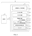
電子装置10が動作するかもしれないシステムの概略図を図2に示す。図2に示すように、システム11は、基地局21のような無線ネットワーク装置を含んでもよい。基地局21のような基地局は、携帯電話ネットワークまたは他の無線ネットワーク装置に関連してもよい。装置10は、無線リンク23(例えば携帯電話リンクまたは他の無線通信リンク)を介して基地局21と通信してもよい。
A schematic diagram of a system in which the
装置10は、記憶装置および処理回路28のような制御回路を含んでもよい。記憶装置および処理回路28は、ハードディスクドライブ記憶装置、不揮発性メモリ(例えば、ソリッドステートドライブを形成するように構成される、フラッシュメモリまたは他の電気的にプログラム可能な読み出し専用メモリ)、揮発性メモリ(例えば、スタティックランダムアクセスメモリまたはダイナミックランダムアクセスメモリ)などのような記憶装置を含んでもよい。記憶装置および処理回路28と無線通信回路34の制御回路のような他の制御回路における処理回路は、装置10の動作を制御するために用いられてもよい。この処理回路は、1つ以上のマイクロプロセッサ、マイクロコントローラ、デジタルシグナルプロセッサ、ベースバンドプロセッサ、電力管理部、オーディオコーデックチップ、特定用途向け集積回路などに基づいてもよい。
記憶装置および処理回路28は、装置10上で、インターネットブラウジング・アプリケーション、ボイス・オーバー・インターネット・プロトコル(VoIP)通話アプリケーション、電子メールアプリケーション、メディア再生アプリケーション、オペレーティングシステム機能などのような、ソフトウェアを実行するのに用いられてもよい。基地局21のような外部装置との相互作用をサポートするために、記憶装置および処理回路28は、通信プロトコルを実装するのに用いられてもよい。記憶装置および処理回路28を用いて実装されうる通信プロトコルは、インターネットプロトコル、無線ローカルエリアネットワークプロトコル(例えばIEEE802.11プロトコル−WiFiと呼ぶこともある)、ブルートゥースプロトコルのような他の短距離無線通信リンクのためのプロトコル、IEEE802.16(WiMax)プロトコル、ロングタームエボリューション(LTE)プロトコル、モバイル通信用グローバルシステム(GSM)プロトコル、符号分割多元接続(CDMA)プロトコル、及びユニバーサル移動通信システム(UMTS)プロトコルのような、携帯電話プロトコルなどを含む。
Storage and
回路28は、装置10のための制御アルゴリズムを実行するように構成されてもよい。無線周波数スイッチング回路、送受信器回路及び他の装置リソースを制御するために、制御アルゴリズムを用いてもよい。例えば、特定のアンテナを信号の送信と受信との少なくともいずれかの使用に切り替えるように、無線回路34を設定するために、制御アルゴリズムを用いてもよく、又は、制御アルゴリズムは、複数のアンテナを同時に使用するように切り替えてもよい。また、送信器と受信器とを所望の周波数へ調整し、タイマを実装し、測定された装置の動作パラメータと所定の基準とを比較するなどのために、送信器と受信器とを有効化し、無効化するために、制御アルゴリズムを用いてもよい。
いくつかのシナリオでは、センサ信号と、受信信号(例えば受信パイロット信号、受信ページング信号、受信音声呼トラフィック、受信制御チャネル信号、受信データトラフィックなど)の品質を反映する信号とを収集するのに、回路28を用いてもよい。装置10において構成される信号品質測定値の例は、ビットエラーレート測定値、信号対雑音比測定値、到来する無線信号に関する電力量の測定値、受信信号強度インジケータ(RSSI)情報(RSSI測定値)に基づくチャネル品質測定値、受信信号符号電力(RSCP)情報(RSCP測定値)に基づくチャネル品質測定値、参照シンボル受信電力(RSRP測定値)、信号対干渉比(SINR)及び信号対雑音比(SNR)情報(SINR及びSNR測定値)に基づくチャネル品質測定値、Ec/Io又はEc/Noデータ(Ec/Io及びEc/No測定値)のような信号品質データに基づくチャネル品質測定値などを含む。この情報と他のデータは、装置10の無線回路をどのように設定するかを制御するのに用いられてもよく、そうでなければ、装置10を制御し、設定するのに用いられてもよい。
In some scenarios, to collect sensor signals and signals that reflect the quality of the received signal (eg, received pilot signal, received paging signal, received voice call traffic, received control channel signal, received data traffic, etc.) The
データを装置10へ供給することを可能とし、データを装置10から外部装置へ提供することを可能とするために、入力出力回路30を用いてもよい。入力出力回路30は、入力出力装置32を含んでもよい。入力出力装置32は、タッチスクリーン、ボタン、ジョイスティック、クリックホイール、スクローリングホイール、タッチパッド、キーパッド、キーボード、マイク、スピーカ、音源、バイブレータ、カメラ、センサ、発光ダイオード及び他の状態表示器、データポートなどを含んでもよい。ユーザは、入力出力装置32を介してコマンドを供給することにより、装置10の動作を制御することができ、状態情報および他の出力を入力出力装置32の出力リソースを用いて装置10から受け取ってもよい。
An input /
無線通信回路34は、1つ以上の集積回路、電力増幅回路、低雑音入力増幅器、パッシブRF部品、1つ以上のアンテナ、及びRF無線信号を処理するための他の回路から形成される、無線周波数(RF)送受信器回路を含んでもよい。
The
無線通信回路34は、(例えば、衛星ナビゲーション信号を1575MHzで受信するための)全地球測位システム(GPS)受信器回路35のような衛星ナビゲーションシステム受信器回路を含んでもよい。送受信器回路36は、WiFi(IEEE802.11)通信のための関連する帯域、例えば2.4GHz及び5GHz帯域を処理してもよく、2.4GHzブルートゥース通信帯域を処理してもよい。回路34は、700MHz、850MHz、900MHz、1800MHz、1900MHz、及び2100MHzのような携帯電話帯域、又は他の注目の携帯電話帯域における無線通信を処理するために、携帯電話送受信器回路38を使用してもよい。無線通信回路34は、必要に応じて、他の短距離及び長距離無線リンクのための回路(例えばWiMax回路など)を含むことができる。無線通信回路34は、例えば、ラジオ及びテレビ信号を受信するための無線回路、ページング回路などを含んでもよい。WiFiおよびブルートゥースリンク及び他の短距離無線リンクにおいては、無線信号は、典型的には、数十又は数百フィートを超えてデータを運ぶために使用される。携帯電話リンク及び他の長距離リンクでは、無線信号は、典型的には、数千フィート又は数マイルを超えてデータを運ぶために使用される。
The
無線通信回路34は、アンテナ40を含んでもよい。アンテナ40は、あらゆる適切なタイプのアンテナを用いて形成されてもよい。例えば、アンテナ40は、ループアンテナ構造、パッチアンテナ構造、逆Fアンテナ構造、クローズドスロットアンテナ及びオープンスロットアンテナ構造、平面逆Fアンテナ構造、ヘリカルアンテナ構造、ストリップアンテナ、モノポール、ダイポール、これらのデザインのハイブリッドなどから形成され、共振素子を伴うアンテナを含んでもよい。異なる種類のアンテナは、異なる帯域及び帯域の組み合わせのために用いられてもよい。例えば、1つの種類のアンテナは、(例えば、WiFiトラフィック又は他の無線ローカルエリアネットワークのトラフィックを処理するための)ローカル無線リンクアンテナを形成するのに用いられてもよく、もう1つの種類のアンテナは、(例えば、音声呼及びデータセッションのようなセルラネットワークのトラフィックを処理するための)遠隔の無線リンクアンテナを形成するのに用いられてもよい。図1に関連して説明したように、装置10の中に複数の携帯電話アンテナがあってもよい。例えば、1つの携帯電話アンテナが装置10の領域24に、もう1つの携帯電話アンテナが装置10の領域22にあってもよい。これらのアンテナは固定されていてもよいし、調節可能であってもよい。
The
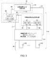
制御アルゴリズムを実行するための制御コードを記憶し、実行するように構成される制御回路は、装置10を制御することができる。図3に示すように、制御回路42は、記憶装置および処理回路28(例えばマイクロプロセッサ、メモリ回路など)を含んでもよく、ベースバンドプロセッサ集積回路58を含んでもよい。ベースバンドプロセッサ58は、無線回路34の部分を形成してもよく、メモリと処理回路とを含んでもよい(すなわち、ベースバンドプロセッサ58は、装置10の記憶装置および処理回路の一部を形成すると考えられる)。
A control circuit configured to store and execute control code for executing the control algorithm can control the
ベースバンドプロセッサ58は、記憶装置および処理回路28(例えば、マイクロプロセッサ、不揮発性メモリ、揮発性メモリ、他の制御回路など)へ、パス48を介してデータを提供する。パス48上のデータは、受信電力、送信電力、フレームエラーレート、ビットエラーレート、受信信号強度インジケータ(RSSI)情報に基づくチャネル品質測定値、受信信号符号電力(RSCP)情報に基づくチャネル品質測定値、参照シンボル受信電力(RSRP)情報に基づくチャネル品質測定値、信号対干渉比(SINR)及び信号対雑音比(SNR)情報に基づくチャネル品質測定値、Ec/Io又はEc/Noデータのような信号品質データに基づくチャネル品質測定値、電子装置からの要求に対応する応答(肯定応答)が携帯電話の電波塔から受信されているかの情報、ネットワークアクセス手順が成功したかの情報、いくつの再送が電子装置とセルラの電波塔との間のセルラリンクを介して要求されているかの情報、シグナリングメッセージの消失を受けたかの情報、ページング信号が無事に受信されたかの情報、および無線回路34の性能を反映する他の情報のような、受信信号に対する無線(アンテナ)性能のメトリクスに関連する未加工のおよび処理されたデータを含む。この情報は、記憶装置および処理回路28とプロセッサ58との少なくともいずれかにより解析されてもよく、それに応じて、記憶装置および処理回路28(または、必要に応じて、ベースバンドプロセッサ58)は、無線回路34を制御するための制御コマンドを発行してもよい。例えば、記憶装置および処理回路28がパス52及びパス50上に制御コマンドを発行してもよく、ベースバンドプロセッサ58はパス46及びパス51上にコマンドを発行してもよく、その両方が行われてもよい。
無線回路34は、無線周波数送受信器回路60及び無線周波数フロントエンド回路62のような無線周波数送受信器回路を含んでもよい。無線周波数送受信器回路60は、送受信器57及び63のような1つ以上の無線周波数送受信器を含んでもよい。いくつかの送受信器は、送信器と受信器との両方を含んでもよい。必要に応じて、1つ以上の送受信器は、(例えば、受信ダイバーシティ手法を実装するのに用いるために)受信回路を備えるが、送信器回路を備えなくてもよい。図3の例示の構成に示すように、送受信器57は送信器59のような送信器と受信器61のような受信器を含んでもよく、また、送受信器63は送信器67のような送信器と受信器65のような受信器とを含んでもよい。
ベースバンドプロセッサ58は、送信されるべきデジタルデータを記憶装置および処理回路28から受信してもよく、パス46と無線周波数送受信器回路60とを、対応する無線周波数信号を送信するのに用いてもよい。無線周波数フロントエンド62は、無線周波数送受信器60とアンテナ40との間に接続されてもよく、無線周波数送受信器回路60により生成される無線周波数信号をアンテナ40へ搬送するのに用いられてもよい。無線周波数フロントエンド62は、無線周波数スイッチ、インピーダンス整合回路、フィルタ、及び、アンテナ40と無線周波数送受信器60との間のインタフェースを形成するための他の回路を含んでもよい。
アンテナ40により受信される到来した無線周波数信号は、無線周波数フロントエンド62、パス54及び56のようなパス、無線周波数送受信器60の受信器回路、及びパス46のようなパスを介してベースバンドプロセッサ58へ供給されてもよい。パス56が送受信器63に関連する信号を処理するのに用いられてよいのに対して、パス54は、例えば、送受信器57に関連する信号を処理するのに用いられてもよい。ベースバンドプロセッサ58は、受信信号を、記憶装置および処理回路28へ供給されるデジタルデータへ変換してもよい。ベースバンドプロセッサ58は、また、受信信号から、送受信器が現在調整されているチャネルに対する信号品質を示す情報を抽出してもよい。例えば、ベースバンドプロセッサと制御回路42の他の回路との少なくともいずれかは、ビットエラーレート測定値、到来した無線信号に関連する電力量の測定値、強度インジケータ(RSSI)情報、受信信号符号電力(RSCP)情報、参照シンボル受信電力(RSRP)情報、信号対干渉比(SINR)情報、信号対雑音比(SNR)情報、Ec/Io又はEc/Noデータのような信号品質データに基づくチャネル品質測定値などを生成するために受信信号を解析してもよい。
The incoming radio frequency signal received by the
無線周波数フロントエンド62は、スイッチング回路を含んでもよい。スイッチング回路は、制御回路42から受信した制御信号(例えば、パス50を介した記憶装置および処理回路28からの制御信号と、パス51を介したベースバンドプロセッサ58からの制御信号との少なくともいずれか)により設定されてもよい。スイッチング回路は、送受信器57をアンテナ40Bへ、そして送受信器63をアンテナ40Aへ、そしてその逆を接続するのに用いられるスイッチ(スイッチ回路)を含んでもよい。パス52を介する記憶装置および処理回路28からの制御信号とパス46を介するベースバンドプロセッサ58からの制御信号との少なくともいずれかにより、無線周波数送受信器回路60は設定されてもよい。
The radio frequency
使用される受信器及びアンテナの数は、装置10に対する動作モードに依存してもよい。例えば、通常のLTEの動作においては、装置10のための受信ダイバーシティ手法を実行するために、アンテナ40Aと40Bがそれぞれの受信器61及び65と共に用いられてもよい。このタイプの構成を使用すると、2つのLTEデータストリームを同時に受信し、ベースバンドプロセッサ58を用いて処理しうる。到来する1Xの呼び出しのための1Xページングチャネルを監視することが望まれる場合、アンテナの1つまたは両方を、1Xページングチャネル信号を受信するのに一時的に用いてもよい。
The number of receivers and antennas used may depend on the mode of operation for the
制御回路42は、1つより多くの無線アクセス技術を処理するためのソフトウェアを実行するために用いられてもよい。例えば、ベースバンドプロセッサ58は、プロトコルスタック1X及びプロトコルスタックLTEのような複数のプロトコルスタック590を実行するためのメモリと制御回路とを含んでもよい。プロトコルスタック1Xは、(例のように)CDMA2000 1XRTTのような第1の無線アクセス技術と関連付けられてもよい。プロトコルスタックLTEは、(例のように)LTEのような第2の無線アクセス技術と関連付けられてもよい。動作の間、装置10は1X機能を処理するためにプロトコルスタック1Xを用いてもよく、LTE機能を処理するためにプロトコルスタックLTEを用いてもよい。必要に応じて、装置10において追加のプロトコルスタック、追加の送受信器、追加のアンテナ40、及び他の追加のハードウェアとソフトウェアとの少なくともいずれかを用いてもよい。図3の構成は一例にすぎない。
The
LTE及び1Xトラフィックをサポートするのにベースバンドプロセッサ58と無線周波数回路60とを使用できる構成を用いる図3の無線回路を実装することによる、装置10のコストと複雑性とを最小化することが望まれるかもしれない。
Minimizing the cost and complexity of
LTE無線アクセス技術が一般にデータトラフィックを運ぶのに用いられてもよい一方で、1X無線アクセス技術は一般に、音声トラフィックを運ぶのに用いられてもよい。1Xの音声呼がLTEデータトラフィックにより妨害されないことを確実にするため、1Xの動作は、LTEの動作に優先してもよい。到来するページング信号のために1Xページングチャネルを監視することのような動作が、不必要にLTEの動作を中断させないことを確実にするために、制御回路42は、可能であればいつでも、無線リソースがLTE機能と1X機能との間で共有されるように、装置10の無線回路を設定することができる。
While LTE radio access technology may generally be used to carry data traffic, 1X radio access technology may generally be used to carry voice traffic. To ensure that 1X voice calls are not disturbed by LTE data traffic, 1X operation may take precedence over LTE operation. In order to ensure that operations such as monitoring the 1X paging channel for incoming paging signals do not unnecessarily interrupt LTE operation, the
ユーザに1Xの呼が到来すると、1Xネットワークは、1Xページングチャネル上で(呼び出し(page)と呼ばれることがある)ページング信号を、基地局21を用いて装置10へ送信してもよい。装置10が到来した呼び出しを検出すると、装置10は、到来した1Xの呼を設定し、受信するために、適切な処置(例えば、呼確立手順)を行うことができる。呼び出しは、装置10のような装置が呼び出しを無事受信するための複数の機会を有することができるように、典型的には、ネットワークにより固定時間間隔において数回送信される。
When a 1X call arrives for a user, the 1X network may send a paging signal (sometimes called a page) on the 1X paging channel to the
適切な1Xの呼び出しの受信は、装置10の無線回路を1Xページングチャネルに合わせることを要求する。送受信器回路60が1Xページングチャネルに合わせない場合、又はベースバンドプロセッサ58において1Xプロトコルスタックが到来する呼び出しに対してページングチャネルを監視しなかった場合、1Xの呼び出しは失われるであろう。一方、1Xページングチャネルの過度なモニタリングは、アクティブなLTEデータセッションへ悪影響があるかもしれない。
Receipt of an appropriate 1X call requires that the radio circuit of
電力を節約するために、1Xプロトコルスタック及びLTEプロトコルスタックが(スリープモード機能と呼ばれることもある)アイドルモードの動作をサポートすることが望ましいかもしれない。ネットワークオペレータがこの特徴を有効にしている場合、1Xアイドルモードの間、サポートされうる1X音声オペレーションは、クイックページングチャネル(Q−PCH)の復号/監視、ページングチャネルの復号/監視、(装置がその前の登録ゾーンから出た場合の)装置の再登録、装置が圏外状態に入った場合のシステムスキャンの開始、及びネットワーク制御チャネル上のオーバーヘッドメッセージ(例えば、基地局識別情報、ネットワーク識別情報、いずれのオプションの特徴がネットワークオペレータにより有効化されているかの情報などのような情報を運ぶメッセージ)の読み出しを含む。 In order to conserve power, it may be desirable for the 1X protocol stack and the LTE protocol stack to support idle mode operation (sometimes referred to as a sleep mode function). If the network operator has enabled this feature, 1X voice operations that can be supported during 1X idle mode are quick paging channel (Q-PCH) decoding / monitoring, paging channel decoding / monitoring, Device re-registration (when exiting previous registration zone), start of system scan when device enters out-of-service state, and overhead message on network control channel (eg, base station identification information, network identification information) Read out messages carrying information such as information on whether the optional features of this are enabled by the network operator.
3つの潜在的な動作状態、ウェイクモード、スリープモード、及び圏外スリープモード、がアイドルモードの動作と関連付けられてもよい。 Three potential operating states may be associated with idle mode operation: wake mode, sleep mode, and out-of-service sleep mode.
ウェイクモードの場合、装置は、呼び出しのためにネットワークから監視され、装置10が稼働中であるかを判定するために監視される。装置が呼び出しを受信しておらず、稼働中である場合、装置はスリープモードに置かれているかもしれない。装置が圏外である場合、利用可能なネットワークを識別するために、システムスキャンが実行されてもよい。利用可能なサービスがない場合、圏外表示を表示してもよく、装置は、ある期間の間、圏外スリープモードに置かれてもよい。圏外スリープモードから起動されると、装置は、もう一度、サービスを検索する。サービスが検出されると、装置は、スリープモードに置かれてもよい。
In the wake mode, the device is monitored from the network for a call and is monitored to determine if
周期的に、装置はスリープモードからウェイクモードへ起動させられるべきである。装置がウェイクモードの間に呼び出しを受信した場合に、通信リンクを確立してもよい。例えば、1Xネットワークにおいて、1X呼(例えば音声呼)を確立するために呼設定動作を実行してもよい。呼が完了した時点で、装置は、スリープモードへ戻されてもよい。 Periodically, the device should be woken up from sleep mode to wake mode. A communication link may be established when the device receives a call while in wake mode. For example, in a 1X network, a call setup operation may be performed to establish a 1X call (eg, a voice call). Upon completion of the call, the device may be returned to sleep mode.
このスリープ−ウェイクのページング周期は、装置10の動作の間、継続的に繰り返されてもよい。各ページング周期につき、装置は到来する呼び出しのためのページングチャネルを監視するために、ある期間の間、起動させられてもよい。電力を節約するために、その後、装置は、到来する呼び出しが検出されない限り、スリープモードに戻されてもよい。
This sleep-wake paging cycle may be continuously repeated during operation of the
装置10は、1X及びLTE無線アクセス技術の両方のためのアクティブモードの動作とアイドルモードの動作とをサポートすることができる。無線回路34と制御回路42とを用いて1X及びLTEの動作を共にサポートする装置10の能力は、1X及びLTEの動作のモードに依存する。
例として、ベースバンドプロセッサ58とプロトコルスタックLTEとがアイドルモードまたはアクティブモードにおけるLTEの動作をサポートするのに使用されながら、ベースバンドプロセッサ58とプロトコルスタック1Xとがアイドルモードにおける1Xの動作をサポートするのに用いられている状況を検討する。1Xページングチャネル上での信号強度が十分である場合、装置10のアンテナの1つ(例えば、図3のアンテナ40B又は40A)を、LTEの動作よりも1Xページングチャネルの監視動作のために使用してもよい。これはLTEの動作のために受信ダイバーシティを実行するのに通常用いられる2つのアンテナのうち1つを一時的に占有するが、無線回路34における残りのアンテナはLTEトラフィックを処理するのに用いられたままでありうる。1Xページング信号強度が、単一の1Xアンテナのみを用いて到来する呼び出しを受信することを可能とするのに十分である環境は、したがって、装置10が、1Xアイドルモードで同時に動作しながら、LTEアイドル又はアクティブモードで動作することを可能とする。
As an example,
装置10が、アクティブな1Xの動作を単一のアンテナを用いて(すなわち、1X信号強度が十分に強いため)サポートすることができる環境においては、残りのアンテナをLTEアイドルモードの動作をサポートするのに用いてもよい。
In an environment where
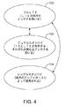
図4は、どのように装置10が動作の間に異なる状態間で遷移しうるかを示す状態図である。LTEトラフィックが装置10とネットワーク23との間で運ばれている通常の動作の間、装置10は、状態100により図示されるように、両方のアンテナ(例えば、図3のアンテナ40A及び40B)を用いてもよい。2つのアンテナの同時使用は、LTEプロトコルに準拠する受信ダイバーシティ手法を装置10が実行することを可能とする。状態100の動作の間、LTEトラフィックの2つの別個の到来ストリームを受信し、処理するのに、プロトコルスタックLTEを使用してもよい。例えば、受信器61とアンテナ40の1つを第1のLTEトラフィックストリームを受信するのに用いてもよく、受信器65と2番目のアンテナ40とを第2のLTEトラフィックストリームを受信するのに用いてもよい。ベースバンドプロセッサ58に、パス46を介してこれらの2つの並列LTEデータストリームを供給してもよく、ベースバンドプロセッサ58は、到来トラフィックを結合して、記憶装置および処理回路28のような装置10の回路のためのデータにしてもよい。LTEデータを送信するのに単一の無線周波数送信器(例えば送信器59)を装置10が用いる環境において、回路42は、送信器59からの送信信号がアンテナ40Aとアンテナ40Bとのいずれかに送られるように、無線周波数送受信器回路60と無線周波数フロントエンド回路62とを設定してもよい。LTEデュアルアンテナのアイドルモードの動作は、状態100においても実行されてもよい。
FIG. 4 is a state diagram showing how the
装置10が到来する1Xの呼を逃さないことを確実にするために、装置10は、LTE機能の一部又はすべてを絞り、1Xの呼び出しの監視動作を実行する状態へ、周期的に遷移してもよい。装置10の制御回路42は、例えば、図4の状態102又は状態104へ装置10を遷移させてもよい。
To ensure that the
制御回路42は、状態102又は状態104へ遷移するかを判定するために、信号品質測定値(例えば受信信号強度インジケータ、又は受信信号品質の他の測定値)を用いてもよい。信号品質が十分である場合、装置10は、1つのアンテナがLTEのために用いられると共に1つのアンテナが1X(例えば1Xアクティブモードの動作又は1Xの呼び出し監視動作)のために使用される状態102へ遷移してもよい。信号品質がより低い場合は、1Xの呼び出し監視動作に対処するための複数のアンテナの使用が要求されてもよく、したがって、装置10は、2つのアンテナが1Xの動作のために(例えば、到来する呼び出しのための1Xページングチャネルの監視に)使用される状態104へ遷移してもよい。
The
装置10において判定のために形成される信号品質測定値の例は、ビットエラーレート測定値、信号対雑音比測定値、到来する無線信号に関連する電力量の測定値、受信信号強度インジケータ(RSSI)情報(RSSI測定値)に基づくチャネル品質測定値、受信信号符号電力(RSCP)情報(RSCP測定値)に基づくチャネル品質測定値、参照シンボル受信電力(RSRP測定値)、信号対干渉比(SINR)及び信号対雑音比(SNR)情報(SINR及びSNR測定値)に基づくチャネル品質測定値、Ec/Io又はEc/Noデータ(Ec/Io及びEc/No測定値)に基づくチャネル品質測定値などを含む。
Examples of signal quality measurements formed for determination in
1つの説明のための構成を使用して、装置10は、1X信号品質が閾値TH1より大きいRSSIの値を有するという条件で、1Xの呼び出し監視動作を実行するために状態100から状態102へ遷移するとともに、1X信号品質がTH1より小さいRSSIの値を有する場合は、1Xの呼び出し監視動作を実行するために状態100から状態104へ遷移するであろう。状態102又は状態104への遷移をするかを判定するために、他の信号品質測定値と閾値とが制御回路42によって使用されてもよい。RSSI信号品質測定値の使用は単なる例である。
Using one illustrative configuration,
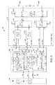
図5は、装置10を実装するのに使用されうる例示の回路を示す回路図である。図5の説明のための例において、装置10は2つのアンテナ−アンテナ40A及び40Bを有する。必要に応じて、装置10は、図3に関連して説明したように、追加のアンテナ40を有してもよい。図5の装置10は、2つの受信器(受信器回路61及び受信器回路65)と送信器(送信器回路59)とを含む無線周波数送受信器回路60を有する。ベースバンドプロセッサ58は、LTEの動作に対処するためのプロトコルスタックLTEと1Xの動作に対処するためのプロトコルスタック1Xのようなプロトコルスタック590を有する。パス46はベースバンドプロセッサ58を無線周波数送受信器回路60に接続するのに用いられてもよい。無線周波数送受信器回路60は、無線周波数フロントエンド回路62を介してアンテナ40A及び40Bへ接続されてもよい。
FIG. 5 is a circuit diagram illustrating an exemplary circuit that may be used to implement the
ベースバンドプロセッサ58からのデータは、パス46におけるパスTXを介して送信器回路59へ運ばれてもよい。パス106は、送信されるべきデータを低域通過フィルタ108へ運ぶのに用いられてもよい。送信器の局部発振器112は局部発信出力信号をアップコンバータ回路110へ供給してもよい。アップコンバータ回路110は、低域通過フィルタ108からのデータ信号をアップコンバートし、対応する無線周波数出力信号を増幅器114へ供給してもよい。増幅器114は、無線周波数信号バージョンの送信データを増幅し、この信号を多重化器回路116(または他の適切なスイッチング回路)へ提供してもよい。多重化器116は、送信データがプロトコルスタックLTEにより供給されているLTEデータである場合にデータをパスLTE TXへ供給し、送信データがプロトコルスタック1Xにより提供されている1Xデータである場合にパス1X TXへデータを供給してもよい。多重化器回路116と送受信器60の他の回路の状態は、ベースバンドプロセッサ58と記憶装置および処理回路28(例えば図3の制御回路42)との少なくともいずれかにより供給される制御信号により制御されてもよい。
Data from
無線周波数フロントエンド62は、フィルタと、送受信器回路60とアンテナ40A及び40Bとの間で到来信号と出力信号とをルーティングするためのスイッチング回路とを含んでもよい。例えば、無線周波数フロントエンド回路62は、スイッチ122のようなクロスオーバー(2極双投、double-pole-double-throw)スイッチの機能を実装するスイッチング回路を含んでもよい。スイッチ122の状態は、制御回路42からパスC3上で受信される制御信号により制御されてもよい。第1の状態において、スイッチ122は、信号をポートP10とP11との間でルーティングすると共に、信号をポートP12とP13との間でルーティングしてもよい。第2の(逆の)状態では、スイッチ122は、ポートP10をポートP13へ接続すると共に、ポートP12をポート11へ接続してもよい。
The radio frequency
スイッチ122の状態は、それぞれのアンテナにいずれの受信器及び送信器回路が接続されるかを制御するのに用いられてもよい。例えば、スイッチ122の状態は、送信信号がアンテナ40Aを介して送信されるか、アンテナ40Bを介して送信されるかを制御するのに用いられてもよい。スイッチ122がその第1の状態にある場合は、パスLTE TXからのLTE信号又はパス1X TXからの1X信号のような送信信号は、アンテナ40Aを通じて送信されてもよい。スイッチ122がその第2の状態にある場合は、パスLTE TXからのLTE信号又はパス1X TXからの1X信号のような送信信号はアンテナ40Bを通じて送信されてもよい。
The state of the
パスLTE TX上の送信LTE信号は増幅器128により増幅されてもよい。デュプレクサフィルタ回路118は、信号をその周波数に基づいてルーティングしてもよい。スイッチ120のポートP4から受信される、到来する無線周波数信号は、パスLTE RX1へルーティングされてもよい。増幅器128の出力からの送信信号はスイッチ120のポートP4へルーティングされてもよい。
The transmitted LTE signal on path LTE TX may be amplified by
多重化器116からのパス1X TX上の送信1X信号は、増幅器130により増幅されてもよい。デュプレクサフィルタ回路126は、信号をその周波数に基づいてルーティングしてもよい。スイッチ120のポートP5から受信される無線周波数信号は、パス1X RX1へルーティングされてもよい。増幅器130の出力からの送信信号はスイッチ120のポートP5へルーティングされてもよい。
The transmit 1X signal on
無線周波数スイッチ120のような無線周波数フロントエンド回路62における無線周波数スイッチング回路は、制御信号パスC1上で受信される制御回路42からの制御信号により制御されてもよい。第1の状態においては、無線周波数スイッチ120は、ポートP6をポートP4へ接続してもよく、第2の状態においては、無線周波数スイッチ120はポートP6をポートP5へ接続してもよい。ポートP4とポートP6とが接続される場合、アンテナ構造40からの受信無線周波数信号は、ポートP6からポートP4へルーティングされてもよく、送信無線周波数信号は、アンテナ構造40を介しての送信のために、ポートP4からポートP6へルーティングされてもよい。ポートP5とポートP6とが接続される場合、アンテナ構造40からの受信無線周波数信号は、ポートP6からポートP5へルーティングされてもよく、送信無線周波数信号は、アンテナ構造40を介しての送信のために、ポートP5からポートP6へルーティングされてもよい。
The radio frequency switching circuit in the radio frequency
無線周波数フロントエンド回路62は、また、無線周波数スイッチ124のような無線周波数スイッチング回路を含んでもよい。無線周波数スイッチ124は、制御回路42により設定されてもよい。具体的には、無線周波数スイッチ124は、制御回路42からの制御信号を制御信号入力パスC2上で受信してもよい。パス2で受信された制御信号に応答して、無線周波数スイッチ124は、ポートP7とポートP9とが結合される第1の状態又は信号パスがポートP8及びポートP9の間に形成される第2の状態にセットされてもよい。その第1の状態(すなわち、LTEトラフィックを受信するためにスイッチ124を設定する場合)において、クロスオーバースイッチ122からの受信信号は、ポートP9からポートP7と関連する信号パスLTE RX2へルーティングされてもよい。その第2の状態(すなわち、1Xトラフィックを受信するためにスイッチ124を設定する場合)において、クロスオーバースイッチ122からの受信信号は、ポートP9から、ポートP8と関連する信号パス1X RX2へルーティングされてもよい。
Radio frequency
無線周波数送受信器回路60に関連するスイッチング回路は、無線周波数フロントエンド回路62における4つの受信パス(LTE RX1、1X RX1、LTE RX2、及び1X RX2)からの信号を、受信器回路61及び65へ選択的にルーティングするのに用いられてもよい。多重化器138は、例えば、パスLTE RX1及び1X RX1上で到来する無線周波数信号を受信し、これらのパスの選択された1つから、受信器61のダウンコンバータ回路136へ、信号をルーティングしてもよい。多重化器146は、パスLTE RX2及び1X RX2上で到来する無線周波数信号を受信し、これらのパスの選択された1つから、受信器65のダウンコンバータ回路148へ、信号をルーティングしてもよい。
The switching circuit associated with the radio
局部発振器RX LOは、受信器61及び65のための局部発信出力信号を生成してもよい。図5に示すように、例えば、局部発振器140は、スイッチング回路144のポートP1において受信される、周波数f2における無線周波数出力信号を生成してもよい。局部発振器142は、スイッチ144のポートP2と、受信器61におけるダウンコンバータ回路136へ供給される、周波数f1における無線周波数出力信号を生成してもよい。スイッチング回路116、138、146及び144は、制御回路42(例えばベースバンドプロセッサ58と記憶装置および処理回路28との少なくともいずれか)から受信した制御信号により制御されてもよい。
The local oscillator RX LO may generate a local transmission output signal for the
受信器61を使用してLTE信号を処理することが要求される場合、多重化器138は、パスLTE RX1からダウンコンバータ回路136へ信号をルーティングするために用いられてもよい。局部発振器142からの局部発振出力とのミキシングの後に、パスLTE RX1からのLTE信号は、低域通過フィルタ134、増幅器132及びパスRX1を介して、ベースバンドプロセッサ58へ供給されてもよい。ベースバンドプロセッサ58は、受信LTE信号を処理するためにプロトコルスタックLTEを用いてもよい。
受信器61を使用して1X信号を処理することが要求される場合、多重化器138は、パス1X RX1からの信号をダウンコンバータ回路136へルーティングするのに用いられてもよい。局部発振器142からの局部発振出力とのミキシングの後に、パス1X RX1からの1X信号は、低域通過フィルタ134、増幅器132、及びパスRX1を介してベースバンドプロセッサ58へ供給されてもよい。ベースバンドプロセッサ58は、受信1X信号を処理するためにプロトコルスタック1Xを用いてもよい。
受信器65を使用してLTE信号を処理することが要求される場合、多重化器146は、パスLTE RX2からの信号を受信器65へルーティングするのに用いられてもよい。受信器65を使用して1X信号を処理することが要求される場合、多重化器146は、パス1X RX2からの信号を受信器65へルーティングするのに用いられてもよい。
スイッチ144の状態は、ダウンコンバータ回路148に、局部発振器140の周波数f2における局部発振出力を供給するか、局部発振器142の周波数f1における局部発振出力を供給するかを決定するために用いられてもよい。スイッチ144は、ダウンコンバータ148へ局部発振器140のf2における出力を供給することが要求される場合はポートP1をポートP3へ接続するように構成されてもよく、ダウンコンバータ148に局部発振器142の周波数f1における出力を供給することが要求される場合はポートP2をポートP3へ接続するように構成されてもよい。多重化器146の出力からの受信した1X又はLTE信号を、局部発振器142からの局部発振出力または局部発振器140からの局部発振出力とミキシングした後に、ダウンコンバータ回路148は、受信した1X又はLTE信号を、低域通過フィルタ150、増幅器152、及びパス46におけるパスRX2を介してベースバンドプロセッサ58へ供給してもよい。ベースバンドプロセッサ58は、パスLTE RX2からのLTE信号を処理するためにプロトコルスタックLTEを、パス1X RX2からの1X信号を処理するためにプロトコルスタック1Xを、用いてもよい。
The state of the
受信ダイバーシティを実装することが要求される動作状態において、スイッチ144は、局部発振器142の周波数f1における出力をダウンコンバータ148へルーティングしてもよい。同時に、ダウンコンバータ136は局部発振器142の周波数f1における出力を受信してもよい。この構成においては、受信器61及び65は、それぞれ、到来する無線周波数信号を同一の周波数(すなわち、周波数f1)で受信してもよく、したがって、到来するLTE又は1X信号のために、2アンテナ受信ダイバーシティ構成を実装するのに用いられてもよい。
In an operating state where it is required to implement receive diversity,
信号強度(例えば受信信号強度インジケータ又は他の信号品質インジケータ情報)が、1Xページング信号を受信するのに単一のアンテナを用いてもよいことを示す場合、アンテナ40A及び40Bのうち1つと受信器61及び65のうち1つが、LTE信号の受信に用いられてもよく、アンテナ40A及び40Bの他方と、受信器61及び65の他方は、1X信号を受信するのに用いられてもよい。無線周波数送受信器回路60におけるそれぞれの受信器を異なる種類のトラフィックを処理するために使用する場合、スイッチ144は、局部発振器140の周波数f2における出力をダウンコンバータ回路148へルーティングするように設定されてもよい。そして、受信器61は、第1の周波数(f1)における到来信号を受信するために用いられてもよく、一方で受信器65は、第1の周波数と異なる第2の周波数における到来信号を同時に受信するために用いられる。回路60と回路62のいずれが設定されるかに応じて、1Xトラフィックが受信器65により処理される(すなわち、パス1X RX2からの1Xトラフィック)一方で、LTEトラフィックは受信器61により処理されてもよく(すなわち、パスLTE RX1からのLTEトラフィック)、又は、1Xトラフィックが受信器61により処理される(すなわち、パス1X RX1からの1Xトラフィック)一方で、LTEトラフィックは受信器65により処理されてもよい(すなわち、パスLTE RX2からのLTEトラフィック)。
If signal strength (eg, received signal strength indicator or other signal quality indicator information) indicates that a single antenna may be used to receive the 1X paging signal, one of
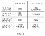
図6は、装置10が、1X及びLTEの動作の、様々なとり得る組み合わせの下で、どのように動作しうるかを説明する表である。1X及びLTEの動作のいくつかの潜在的な組み合わせが、他の組み合わせはリソースの衝突を引き起こしうるが、図5に示すタイプの回路を用いて処理されうる。
FIG. 6 is a table illustrating how the
例として、装置10の1X機能がアイドルである(すなわち、装置10により処理されているアクティブな1Xの呼がなく、装置10は到来する呼のために周期的に1Xページングチャネルを監視している)シナリオと、(測定されたRSSI値又は他の信号品質ファクタとして示される)受信1X信号強度が、装置10の2つのアンテナのうちの1つのみを用いて、装置10が1Xページングチャネルを監視することが可能とするのに十分であるシナリオについて検討する。これらのシナリオは、図6の表の第1行によって表される。図6の表の第1行に示されるように、装置10が(到来するLTEの呼び出しを監視している)LTEアイドル状態で動作している場合、装置の性能は満足されうると共に、装置10がLTEアクティブ状態で動作している場合は、装置の性能は多少劣化しうる。
As an example, the 1X function of
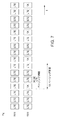
図7は、LTEアイドル及び1Xアイドルの動作(図6の表の第1行の左列)を処理するために装置10を使用している間に生じる、無線の動作のタイプを図解している。LTE及び1X機能がアイドルであるため、送信器TXに関連する動作はない。ほとんどの期間の間、無線周波数送受信器60と無線周波数フロントエンド62のスイッチング回路は到来するアンテナの信号をパスLTE RX1及びLTE RX2へルーティングするように設定されうる。スイッチ144は、受信器61と受信器65が、同一の局部発振周波数(f1)を用いてパスLTE RX1及びLTE RX2上で信号を受信するように設定されてもよい(すなわち、装置10は、到来するLTEの呼び出しのために周波数f1においてLTEページングチャネルを監視するために、受信ダイバーシティモードで両方のアンテナを用いるように設定されてもよい)。LTEの呼び出しの監視が実行される周期は、図7において、第1の受信器(RX1)と第2の受信器(RX2)の両方に対して、「LTE」呼び出し監視のボックスの存在により示されている。第1の受信器RX1は、例えば、受信器61に対応してもよく、第2の受信器RX2は、例えば、受信器65へ対応してもよい(またはその逆でもよい)。
FIG. 7 illustrates the types of radio activity that occur while using the
1Xページング周期は、LTEページング周期より長くてもよい。結果として、装置10は、周期的に、第2の受信器RX2を、LTEページングチャネルに代えて、1Xページングチャネルを監視するのに用いる必要がありうる。このタイプの動作をサポートするために、無線周波数送受信器回路60と無線周波数フロントエンド62の構成は、制御回路42によって再設定されてもよい。具体的には、スイッチ144は、受信器61が周波数f1で動作する一方で受信器65が周波数f2で動作するように、ポートP1をポートP3へ接続するように設定されてもよい。スイッチ120は、アンテナの1つからの受信信号をパスLTE RX1へルーティングするように、ポートP6をポートP4へ接続するように設定されてもよい。スイッチ124は、他方のアンテナからの受信信号をパス1X RX2へルーティングするようにポートP9をポートP8へ接続するように設定されてもよい。図5の例では、信号をルーティングするためにスイッチング回路が用いられる。2つの無線周波数帯域のみが含まれる構成においては、装置10において信号をルーティングするためにダイプレクサ回路が用いられてもよい。図5のスイッチング回路のようなスイッチング回路の使用は、より多くの周波数帯域が含まれている場合に好ましいかもしれない。
The 1X paging cycle may be longer than the LTE paging cycle. As a result, the
図7に示すように、LTE信号よりも到来する呼び出しのための1Xページングチャネルの監視のために受信器RX2を周期的に用いることにより、1Xの呼び出しとLTEの呼び出しとを同時に監視することができる。(図7において「1X」のラベルが付された四角形により図解される)これらの期間の間、装置10のアンテナの1つは、信号をパス1X RX2へ供給するために用いられ、一方で、回路60は、このパス上で(周波数f2において)到来する1Xの呼び出しを監視する。同時に、アンテナの残りの1本と回路RX1とを用いて、LTEアイドル(呼び出し監視)動作を実行することができる。アンテナのうち1本が1Xの呼び出しを監視するのに用いられている期間の間、両方のアンテナと受信器とを、LTEの呼び出しの監視に同時に用いることができないが、LTEページングチャネルの監視のための受信ダイバーシティのこの周期的な瞬時の喪失は、一般的に受け入れることができるものである。したがって、図6の表の第1行の左列に示すように、性能は満足される。
As shown in FIG. 7, it is possible to simultaneously monitor 1X and LTE calls by using the receiver RX2 periodically to monitor the 1X paging channel for incoming calls than LTE signals. it can. During these periods (illustrated by a square labeled “1X” in FIG. 7), one of the antennas of
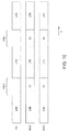
図6の表の第1行の右列の項目により図解されるように、呼び出しのために1Xチャネルを同時に監視しながら(すなわち、装置を1Xアイドルモードで動作させながら)装置10をLTEアクティブ状態で動作させようとすると、LTEの性能は少々劣化しうる。図8は、この状況で装置10がどのように動作しうるかを示す図である。図8に示すように、送信器TXは、(例えば図5のパスLTE TXと関連するアンテナ40の1つとを用いて)LTEデータを送信するために用いられてもよい。
As illustrated by the right column entry in the first row of the table of FIG. 6,
図8の例では、初期的には、LTEデータが装置10により受信ダイバーシティ構成を用いて受信されている。例えば、図8の時刻T1のような時刻においては、呼び出しのための1Xページングチャネルを監視することが要求される前に、両方のアンテナを用いると共に対応する受信器RX1及びRX2を用いて、LTEデータが受信されてもよい。呼び出しのために1Xチャネルを監視することが要求されるとき、通常のLTE受信ダイバーシティ動作は中断されうる。具体的には、到来する1Xの呼び出しに対する1Xページングチャネルを、受信器RX2に関連するアンテナが監視することができるように、(図8において「1Xウェイク」とラベルが付された期間の間)LTE受信ダイバーシティ動作を中断してもよい。
In the example of FIG. 8, initially, LTE data is received by the
LTE受信ダイバーシティモードと図8の「1Xウェイク」期間の1Xの呼び出し監視動作との間の遷移は、時刻T2のような時刻において行われてもよい。時刻T2の前(そしてそれに続く1Xウェイク状態への各エントリの前)のいくつかの送信時間間隔において、装置10は、ネットワーク(例えば図2の基地局21)へ1のランクインジケータを送信してもよい。1のランクインジケータ(または他の適切なチャネル品質インジケータ)は、単一のレイヤのみで(すなわち、受信ダイバーシティ動作の間は通常送信される2つの同時のLTEデータパスのうちの1つのみで)データを送信するようにネットワークに指示する。これは、1Xページングチャネル監視の間、2つのLTEデータパスの1つが利用不能となる場合に、データのロスを防ぐのに役立つ。1Xウェイクの期間の間、1Xページングチャネルが監視されている一方で、受信器RX1が残りの到来するLTEデータストリームを処理することができると共に、送信器TXはLTEデータを送信するのに用いられてもよい。期間1Xウェイクの後に1Xの動作は終わり(スリープへ移行し)、(1Xスリープの期間の間、)1Xの呼び出し監視のために一時的に使用されたアンテナと受信器との使用は、装置10が対応するランクインジケータ(または他の適切なチャネル品質インジケータ)をLTEネットワークへ送信することに伴って、LTEデータストリームの1つの受信に係る使用に戻されてもよい。
The transition between the LTE reception diversity mode and the 1X call monitoring operation in the “1X wake” period of FIG. 8 may be performed at a time such as time T2. In some transmission time intervals prior to time T2 (and prior to each entry to the 1X wake state),
図8(及び図6の表の第1行の右列)に関連して説明したタイプの構成に伴い、LTEサービスの中断はないが、1Xウェイクの期間の間にLTEデータを受信するための第2のアンテナと受信器とを一時的に失うことに起因して、受信LTEデータスループットは劣化する。 With the type of configuration described in connection with FIG. 8 (and the right column in the first row of the table of FIG. 6), there is no interruption of LTE service, but for receiving LTE data during the 1X wake period. Due to the temporary loss of the second antenna and the receiver, the received LTE data throughput is degraded.
いくつかの状況では、受信信号品質が悪く、したがって、単一のアンテナのみを用いて1Xページング信号を受信しようとすることが望ましくない。装置10がこのタイプの状況が発生したことを検出した場合、1Xの呼び出し監視動作(1Xアイドルモードの動作)を、両方のアンテナ(すなわち、アンテナ40A及び40B)と送受信器回路60における対応する受信器61及び65とを用いて実行してもよい。図6の表の第2行の左列に示されるように、ページングインスタンスが衝突しない場合は、1Xアイドル動作とLTEアイドル動作とを同時に実行することができる。図6の表の第2行の右列に示されるように、1Xアイドル動作とLTEアクティブモードの動作を同時に実行する試みは、LTEの動作の中断を招くであろう。
In some situations, the received signal quality is poor and therefore it is not desirable to attempt to receive a 1X paging signal using only a single antenna. If the
1XアイドルモードとLTEアイドルモードの動作の間、スイッチ120は、受信信号をパス1X RX1へルーティングするためにポートP6をポートP5へ接続するように設定されてもよい。スイッチ124は、受信信号をパス1X RX2へルーティングするように設定されてもよい。スイッチ144は、パスRX2上及びパスRX1上の信号が同一周波数に対応するように、局部発振器142からの信号をポートP3へルーティングするように設定されてもよい。周波数は、装置10がLTEページングチャネルを監視しているか、1Xページングチャネルを監視しているかに応じて調整されてもよい。
During operation in 1X idle mode and LTE idle mode, switch 120 may be configured to connect port P6 to port P5 to route the received signal to
図9は、1XアイドルモードとLTEアイドルモードの動作を同時に実行する場合に装置10がどのように動作するかを示す図である。LTEがアイドルモードであり、したがって、(この例では)送信器TXはLTEデータを送信するのに使用されていない。(図9で「LTE」とラベルが付された)いくつかの期間の間、LTEの呼び出しのために、LTEページングチャネルを監視してもよい。両方のアンテナと受信器61及び65は、これらの監視動作に用いられてもよい(すなわち、装置10はLTE受信ダイバーシティモードで運用されてもよい)。1Xページング周期ごとに、送受信器回路60は、図9において「1X」とラベルが付された四角形により示されるように、1Xの呼び出しを監視できるように1Xページングチャネルに調整されてもよい。この例では、装置10が信号品質が比較的低いことを検出しているため(例えば、先立つページング周期のウェイクピリオドの間にRSSIが所定の閾値より低く測定されたため)、装置10(例えば制御回路42)は、1X受信ダイバーシティを用いて(すなわち、両方のアンテナ40を用いると共に両方の受信器61及び65を用いて)1Xの呼び出しを監視するように、無線回路34を設定する。1X受信ダイバーシティの使用は、LTEページング周期を逃すことを周期的に招くという犠牲のもとではあるが、信号受信を改善する。
FIG. 9 is a diagram showing how the
1XアイドルモードとLTEアクティブモードの同時動作(図6の表の第2行の右列)の試行に対応する、図10の図は、PINTの期間の間(すなわち、両方のアンテナが1Xの呼び出しの監視のために1X受信ダイバーシティモードで使用される場合)、どのように周期的にLTEの動作が中断されるかを示している。装置10は、ネットワーク(図2の基地局21)へ、1Xの呼び出し監視期間の数送信時間間隔(TTI)前に、ネットワークにデータ送信を縮小することを指示する0のランクインジケータ(または他の適切なチャネル品質インジケータ)をネットワークへ送信することによって、予期されるLTEの中断を通知してもよい。それに応答して、ネットワークは、PINTの期間の間、装置10へのデータ送信を停止または少なくとも縮小し、PINTの期間の間のLTEサービスの中断の影響を最小化するであろう。
The diagram of FIG. 10, corresponding to a trial of simultaneous operation of 1X idle mode and LTE active mode (right column in the second row of the table of FIG. 6), is for the period of PINT (ie, both antennas are calling 1X) (When used in 1X receive diversity mode for monitoring), it shows how LTE operation is periodically interrupted. The
図6の表の第3行の左列に示されるように、1つのアンテナを使用する1Xアクティブモードの動作とLTEアイドルモードの動作とを同時に実行することが要求される状況では、装置の動作は満足されうる。受信信号を第1のアンテナからパス1X RXへルーティングすると共に、送信1X信号をパス1X TXから第1のアンテナへルーティングするためにポートP6をポートP5へ接続するようにスイッチ120を設定するようにスイッチをセットすることによって、受信信号を第2のアンテナからパスLTE RX2へルーティングするためにポートP9をポートP7へ接続するようにスイッチ124を設定することによって、そして、受信器65及び61がそれぞれ周波数f2及びf1で動作するように、ポートP1をポートP3へ接続するようにスイッチ144を設定することによって、このシナリオを処理するように、装置10が設定される。1X非受信ダイバーシティモード(1アンテナ)の場合、アンテナの1つと、送信器59と、装置10の受信器の1つと、ベースバンドプロセッサ58とは1Xトラフィックを処理するために用いられており、したがって、図6の表の第3行の右列の項目により示されるように、LTEトラフィックの送信と受信とを同時に処理するためには利用可能なリソースが不十分である(すなわち、LTEアクティブモードの動作をサポートすることができない)。
As shown in the left column of the third row of the table of FIG. 6, the operation of the device in situations where it is required to simultaneously perform 1X active mode operation and LTE idle mode operation using one antenna. Can be satisfied.
図11は、LTEアクティブモードからLTEアイドルモードへ遷移すると共に、1Xアイドルモードから1Xアクティブモードへ遷移する場合の装置10の動作を示すタイミング図である。初期的に、装置10は、LTEアクティブ状態及び1Xアイドル状態で動作している。LTEトラフィックは、LTEデータを送信するための1つのアンテナとLTEデータを受信するための2つのアンテナ(受信ダイバーシティ)を用いて処理されてもよい。周期的に、装置10は、2つのアンテナの1つ(例えば、受信器RX2に関連するアンテナ)を、到来する1Xの呼び出しのための1Xページングチャネルを監視するために用いてもよい(例えば、図11の例における時刻TTにおいて開始する1Xウェイク期間を参照)。時刻TTの数送信時間間隔前に、装置10は、ネットワークにデータの送信を縮小することを(すなわち1つのLTEデータストリームのみを送信するように)指示するために、1のランクインジケータ(または他のチャネル品質インジケータ)をネットワークへ送信してもよく、それにより、1Xの呼び出しを監視するためのRX2受信器と、関連するアンテナとの一時的な使用の間の、LTEの動作への影響を最小化する。
FIG. 11 is a timing diagram illustrating the operation of the
図11に示すように、装置10が到来する1Xの呼び出しを受信すると、装置10は、1Xアクティブモードへ遷移してもよい。(この例では)信号品質は十分であるため、単一のアンテナのみが1Xデータ受信動作に対処するために使用される必要がある。したがって、残りのアンテナを、LTEアイドルモードの動作(到来する呼び出しのためのLTEページングチャネルの監視)に使用することができる。
As shown in FIG. 11, when
図6の表の第4行に示すように、単一のアンテナのみでの動作をサポートするには信号強度が不十分である環境において1Xアクティブモードで動作する場合、LTEの動作は中断するであろう。1X受信ダイバーシティ(2アンテナ)アクティブモードで動作している場合、スイッチング回路120は、ポートP6がポートP5へ接続されるように(2つのアンテナのうち第1のアンテナからの受信アンテナ信号がパス1X RX1へルーティングされるように)設定されてもよく、スイッチング回路124はポートP9がポートP8へ接続されるように(2つのアンテナのうち第2のアンテナからの受信アンテナ信号がパス1X RX2へルーティングされるように)設定されてもよく、スイッチング回路144は、ポートP2がポートP3へ接続されるように(すなわち、受信器61と65とが同一周波数で動作するように)設定されてもよい。送信1X信号は、パス1X TXを用いて処理されてもよい。1Xデータ受信アクティブモードの動作をサポートするための両方のアンテナの使用と、1Xデータ送信動作をサポートするためのアンテナの1つの使用は、LTEアイドルモード(図6の表の第4行の左列)で動作することが要求されるか、LTEアクティブモード(図6の表の第4行の右列)で動作することが要求されるかによらず、LTEの動作を中断するだろう。
As shown in the fourth row of the table of FIG. 6, when operating in 1X active mode in an environment where the signal strength is insufficient to support operation with only a single antenna, LTE operation may be interrupted. I will. When operating in 1X receive diversity (2 antennas) active mode, switching
図12は、1Xアクティブモードの動作をサポートするための装置における両方のアンテナの使用がどのようにLTEの動作を中断しうるかを示すタイミング図である。初期的に、(例えば時刻TW1の前の時刻において)、両方のアンテナはLTEの動作(例えば、LTEアクティブモードの動作又はLTEアイドルモードの動作)のために用いられうる。周期的に(例えば、図12の例における時刻TW1及び時刻TW2のような時刻において)アンテナのうち1つ(例えば、受信器RX2に接続されるアンテナ)は、1Xページングチャネルの監視に用いられうる。 FIG. 12 is a timing diagram illustrating how the use of both antennas in an apparatus to support 1X active mode operation may interrupt LTE operation. Initially (eg, at a time prior to time TW1), both antennas may be used for LTE operation (eg, LTE active mode operation or LTE idle mode operation). Periodically (eg, at times such as times TW1 and TW2 in the example of FIG. 12) one of the antennas (eg, the antenna connected to the receiver RX2) may be used to monitor the 1X paging channel. .
LTEの動作への影響を最小化するために、装置10は、アンテナのうち1つの使用をLTEの動作から1Xの呼び出し監視へ切り替える数送信時間間隔前に(すなわち、時刻TW1及びTW2のような1Xの呼び出し監視時刻の数送信時間間隔前に)、1のランクインジケータ又は他のそのようなチャネル品質インジケータをネットワークへ送信してもよい。それに応答して、ネットワークは、(例えば、2つのアクティブなLTEデータストリームから1つのLTEデータストリームへ送信を縮小すること、又は他の適切な動作を行うことにより)LTEデータ送信を縮小することができ、それによりLTEの動作への影響を最小化する。
In order to minimize the impact on LTE operation, the
図12の例では、到来する1Xの呼び出しは、時刻TW3において検出される。結果として、装置10は、時刻TW3において1Xアクティブモードへ入り、両方のアンテナ(すなわち、受信器RX1に接続されたアンテナと受信器RX2に接続されたアンテナ)を1Xの呼を処理するのに用いる。両方のアンテナが1Xの動作に対処するのに用いられており、したがって、LTEの動作(アクティブモードまたはアイドルモード)は中断する。
In the example of FIG. 12, an incoming 1X call is detected at time TW3. As a result,
実施形態によれば、第1の無線アクセス技術と第2の無線アクセス技術とを用いる通信をサポートする電子装置を用いて無線ネットワークと通信をするための方法であって、少なくとも1つの呼び出しの監視期間の間に、第1の無線アクセス技術に関連するページングチャネルを監視するために電子装置の2つのアンテナのうち第1のアンテナを使用し、一方で第2の無線アクセス技術に関連する無線データトラフィックを運ぶために2つのアンテナのうち第2のアンテナを使用することと、ページングチャネル上での到来する呼び出しの電子装置による検出を伴わない呼び出しの監視期間の完了に応答して、第2の無線アクセス技術に関連する無線データトラフィックを運ぶのに第1のアンテナと第2のアンテナの両方を使用することとを含む方法が提供される。 According to an embodiment, a method for communicating with a wireless network using an electronic device that supports communication using a first radio access technology and a second radio access technology, comprising monitoring at least one call During the period, the first antenna of the two antennas of the electronic device is used to monitor the paging channel associated with the first radio access technology, while the radio data associated with the second radio access technology In response to using the second of the two antennas to carry traffic and completing a call monitoring period without detection by an electronic device of an incoming call on the paging channel, Using both a first antenna and a second antenna to carry radio data traffic associated with radio access technology; No method is provided.
もう1つの実施形態によれば、第1の無線アクセス技術は符号分割多元接続無線アクセス技術を含み、第2の無線アクセス技術はロングタームエボリューション無線アクセス技術を含む。 According to another embodiment, the first radio access technology includes a code division multiple access radio access technology and the second radio access technology includes a long term evolution radio access technology.
もう1つの実施形態によれば、第1のアンテナと第2のアンテナとは、電子装置の対向する端部に配置され、第2の無線アクセス技術に関連する無線データトラフィックを運ぶための第1のアンテナと第2のアンテナの両方の使用は、電子装置の対向する端部に配置された第1のアンテナと第2のアンテナとをロングタームエボリューションのデータトラフィックを受信するために使用することを含む。 According to another embodiment, the first antenna and the second antenna are disposed at opposite ends of the electronic device, and a first for carrying wireless data traffic associated with the second radio access technology. The use of both the second antenna and the second antenna means that the first antenna and the second antenna disposed at opposite ends of the electronic device are used to receive data traffic of long term evolution. Including.
もう1つの実施形態によれば、方法は、電子装置の無線信号品質を測定すること、及びページングチャネルを監視するのに第1のアンテナを単独で使用するか、又はページングチャネルを監視するのに第1のアンテナと第2のアンテナの両方を使用するかを、測定された無線信号品質に少なくとも部分的に基づいて判定することをも含む。 According to another embodiment, the method measures the radio signal quality of the electronic device and uses the first antenna alone to monitor the paging channel or to monitor the paging channel. It also includes determining whether to use both the first antenna and the second antenna based at least in part on the measured radio signal quality.
もう1つの実施形態によれば、無線信号品質を測定することは、ページングチャネルのチャネル品質を示す受信信号強度インジケータを取得することを含む。 According to another embodiment, measuring the radio signal quality includes obtaining a received signal strength indicator that indicates the channel quality of the paging channel.
もう1つの実施形態によれば、方法は、受信信号強度インジケータと所定の閾値とを比較すること、受信信号強度インジケータが所定の閾値を超えるとの判定に応じて、少なくとも1つの呼び出しの監視期間の間、ページングチャネルを監視するために、第1のアンテナを単独で使用すること、及び受信信号強度インジケータが所定の閾値を超えないとの判定に応じて、ページングチャネルを監視するために第1のアンテナと第2のアンテナの両方を使用することをも含む。 According to another embodiment, the method compares the received signal strength indicator with a predetermined threshold and determines that the received signal strength indicator exceeds the predetermined threshold for at least one call monitoring period. During the first time to monitor the paging channel in response to using the first antenna alone and determining that the received signal strength indicator does not exceed the predetermined threshold. Using both the first antenna and the second antenna.
もう1つの実施形態によれば、ページングチャネルを監視するために第1のアンテナと第2のアンテナの両方を使用することは、第1のアンテナと第2のアンテナとを伴うロングタームエボリューションのデータの受信を一時的に中断すること、及び、第1のアンテナと第2のアンテナとを伴うロングタームエボリューションのデータの受信が一時的に中断される間に符号分割多元接続のページング信号のためのページングチャネルを監視するために第1のアンテナと第2のアンテナの両方を使用することをも含む。 According to another embodiment, using both the first antenna and the second antenna to monitor the paging channel is data for long term evolution with the first antenna and the second antenna. For the code division multiple access paging signal while the reception of the data of the long term evolution with the first antenna and the second antenna is temporarily interrupted It also includes using both the first antenna and the second antenna to monitor the paging channel.
実施形態によれば、第1の無線アクセス技術と第2の無線アクセス技術とを用いる無線通信をサポートする電子装置を用いて無線ネットワークと通信をするための方法であって、電子装置の動作の間に、第1の無線アクセス技術に関連するページングチャネルを監視するために電子装置の第1のアンテナと第2のアンテナの両方を使用すること、及び電子装置の動作の少なくとも一部の間、第1のアンテナを使用して第2のアンテナを使用せずに、第2の無線アクセス技術に関連するページングチャネルを監視するために、第1の無線アクセス技術に関連するページングチャネルの監視を少なくとも部分的に中断することを含む方法が提供される。 According to an embodiment, a method for communicating with a wireless network using an electronic device that supports wireless communication using a first wireless access technology and a second wireless access technology, the operation of the electronic device During the use of both the first antenna and the second antenna of the electronic device to monitor the paging channel associated with the first radio access technology, and at least part of the operation of the electronic device, In order to monitor the paging channel associated with the second radio access technology without using the second antenna using the first antenna, monitor at least the paging channel associated with the first radio access technology. A method is provided that includes partially interrupting.
もう1つの実施形態によれば、方法は、電子装置の動作の少なくとももう1つの部分の間、第1のアンテナと第2のアンテナの両方を使用して第2の無線アクセス技術に関連するページングチャネルを監視するために、第1の無線アクセス技術に関連するページングチャネルの監視を中断することを含む。 According to another embodiment, a method includes paging associated with a second radio access technology using both a first antenna and a second antenna during at least another portion of operation of an electronic device. Suspending monitoring of the paging channel associated with the first radio access technology to monitor the channel.
もう1つの実施形態によれば、第1の無線アクセス技術はロングタームエボリューション無線アクセス技術を含み、第2の無線アクセス技術は符号分割多元接続無線アクセス技術を含む。 According to another embodiment, the first radio access technology includes a long term evolution radio access technology and the second radio access technology includes a code division multiple access radio access technology.
もう1つの実施形態によれば、方法は、電子装置を用いて無線チャネル品質を測定すること、測定された無線チャネル品質を所定値と比較することをも含み、第1のアンテナを使用して第2のアンテナを使用せずに、第2の無線アクセス技術に関連するページングチャネルを監視するために、第1の無線アクセス技術に関連するページングチャネルの監視を少なくとも部分的に中断することは、無線チャネル品質が所定値を超えるとの判定に応じて、第1の無線アクセス技術に関連するページングチャネルの監視を少なくとも一時的に中断することと、無線チャネル品質が所定値を超えなかったことの判定に応じて、第2の無線アクセス技術に関連するページングチャネルを監視するために、第1のアンテナと第2のアンテナの両方を使用することを含む。 According to another embodiment, the method also includes measuring radio channel quality using the electronic device, comparing the measured radio channel quality with a predetermined value, and using the first antenna. Suspending at least partially monitoring the paging channel associated with the first radio access technology to monitor the paging channel associated with the second radio access technology without using the second antenna; In response to determining that the radio channel quality exceeds a predetermined value, at least temporarily suspending monitoring of the paging channel associated with the first radio access technology, and that the radio channel quality has not exceeded the predetermined value. Depending on the determination, both the first antenna and the second antenna are used to monitor the paging channel associated with the second radio access technology. Including that.
もう1つの実施形態によれば、無線チャネル品質を測定することは、無線ネットワークにおける無線チャネルに関連する受信信号強度インジケータ情報を収集することを含む。 According to another embodiment, measuring the radio channel quality includes collecting received signal strength indicator information associated with a radio channel in the wireless network.
もう1つの実施形態によれば、電子装置は、無線周波数送受信器回路と、無線周波数送受信器回路を制御する制御回路とを含み、無線周波数送受信器回路は、それぞれ第1及び第2の局部発振器を伴う第1及び第2の受信器を含み、方法は、第1の無線アクセス技術に関連するページングチャネルを監視するために電子装置の第1のアンテナと第2のアンテナとを同時に使用する場合、第1及び第2の局部発振器が共通の周波数における出力を生成するように無線周波数送受信器回路を調整すること、及び、第1のアンテナを使用して第2のアンテナを使用せずに第2の無線アクセス技術に関連するページングチャネルを監視する場合、第1及び第2の局部発振器が異なる周波数における出力を生成するように無線周波数送受信器回路を調整することをも含む。 According to another embodiment, an electronic device includes a radio frequency transceiver circuit and a control circuit that controls the radio frequency transceiver circuit, the radio frequency transceiver circuit comprising first and second local oscillators, respectively. Wherein the method simultaneously uses the first antenna and the second antenna of the electronic device to monitor a paging channel associated with the first radio access technology. Adjusting the radio frequency transceiver circuit so that the first and second local oscillators produce an output at a common frequency, and using the first antenna and the second antenna without using the second antenna. When monitoring the paging channel associated with two radio access technologies, adjust the radio frequency transceiver circuit so that the first and second local oscillators generate outputs at different frequencies Also includes a Rukoto.
もう1つの実施形態によれば、方法は、第1及び第2の局部発振器が異なる周波数において出力を生成するように無線周波数送受信器回路が調整される間に、第1の無線アクセス技術に関連するページング信号を監視するために第1の受信器を使用する一方で、第2の無線アクセス技術に関連するページング信号を監視するために第2の受信器を同時に使用することをも含む。 According to another embodiment, the method relates to a first radio access technology while the radio frequency transceiver circuit is tuned such that the first and second local oscillators generate outputs at different frequencies. Using the first receiver to monitor the paging signal to be used while simultaneously using the second receiver to monitor the paging signal associated with the second radio access technology.
実施形態によれば、第1及び第2のアンテナを有すると共に、第1のアンテナ及び第2のアンテナを使用して無線信号を送信し受信する無線周波数送受信器回路を有する無線電子装置において、第1及び第2の無線アクセス技術の使用をサポートする方法であって、動作の第1のモードにおいて、第1の無線アクセス技術に関連するページングチャネルを監視するために第1のアンテナを使用する一方で、第2の無線アクセス技術に関連するページングチャネルを監視するために第2のアンテナを同時に使用すること、及び、動作の第2のモードにおいて、第1の無線アクセス技術を用いて第1のアンテナを介してデータトラフィックを有効に送信して受信する一方で、第2の無線アクセス技術に関連するページングチャネルを監視するために第2のアンテナを同時に使用することを含む方法が提供される。 According to an embodiment, in a wireless electronic device having first and second antennas and having a radio frequency transceiver circuit for transmitting and receiving radio signals using the first antenna and the second antenna, A method for supporting the use of first and second radio access technologies, wherein in a first mode of operation, the first antenna is used to monitor a paging channel associated with the first radio access technology. Simultaneously using the second antenna to monitor the paging channel associated with the second radio access technology, and using the first radio access technology in the second mode of operation, the first To monitor the paging channel associated with the second radio access technology while effectively transmitting and receiving data traffic via the antenna The method comprising using a second antenna at the same time is provided.
もう1つの実施形態によれば、第1の無線アクセス技術はロングタームエボリューション無線アクセス技術を含み、第2の無線アクセス技術は符号分割多元接続無線アクセス技術を含む。 According to another embodiment, the first radio access technology includes a long term evolution radio access technology and the second radio access technology includes a code division multiple access radio access technology.
もう1つの実施形態によれば、無線電子装置はハウジングを有し、第1及び第2のアンテナはハウジングの対向する端部に配置され、電子装置は第1及び第2のアンテナと無線周波数送受信器回路との間に接続されるスイッチング回路を有し、無線周波数送受信器回路は、第1及び第2の受信器をも含み、方法は、スイッチング回路が信号を第1のアンテナから第1の受信器へルーティングすると共に信号を第2のアンテナから第2の受信器へルーティングする第1の構成において無線電子装置を動作させること、及びスイッチング回路が信号を第1のアンテナから第2の受信器へルーティングすると共に、信号を第2のアンテナから第1の受信器へルーティングする第2の構成において、無線電子装置を動作させることをも含む。 According to another embodiment, the wireless electronic device has a housing, the first and second antennas are disposed at opposite ends of the housing, and the electronic device transmits and receives radio frequencies with the first and second antennas. The radio frequency transceiver circuit also includes first and second receivers, and the method includes: a switching circuit connected to a first antenna; Operating the wireless electronic device in a first configuration for routing to a receiver and routing a signal from a second antenna to a second receiver, and a switching circuit for the signal from the first antenna to the second receiver And operating the wireless electronic device in a second configuration for routing signals from the second antenna to the first receiver.
もう1つの実施形態によれば、方法は、動作の第3のモードにおいて、第2の無線アクセス技術を用いて第2のアンテナを通じてデータトラフィックを有効に送信し受信する一方で、第1の無線アクセス技術に関連するページングチャネルを監視するために第1のアンテナを同時に使用することをも含む。 According to another embodiment, the method effectively transmits and receives data traffic through the second antenna using the second radio access technology in the third mode of operation while the first radio. It also includes simultaneously using the first antenna to monitor the paging channel associated with the access technology.
もう1つの実施形態によれば、方法は、動作の第4のモードにおいて、第1の無線アクセス技術に関連するデータトラフィックを受信するために第1及び第2のアンテナを同時に使用することをも含む。 According to another embodiment, the method also includes simultaneously using the first and second antennas to receive data traffic associated with the first radio access technology in the fourth mode of operation. Including.
もう1つの実施形態によれば、方法は、動作の第4のモードの間に第1の無線アクセス技術に関連するデータトラフィックを受信するために第1及び第2のアンテナの両方を使用することから、第1の無線アクセス技術に関連するデータトラフィックを受信するために第1のアンテナを使用する一方で第1の無線アクセス技術に関連するページングチャネルを監視するために第2のアンテナを使用することへ一時的に切り替えることに備えて、第1の無線アクセス技術に関連するデータの無線電子装置への送信を縮小することを無線ネットワークに指示するために、チャネル品質インジケータを無線電子装置から無線ネットワークへ送信することをも含む。 According to another embodiment, the method uses both the first and second antennas to receive data traffic associated with the first radio access technology during the fourth mode of operation. From the second antenna to monitor the paging channel associated with the first radio access technology while using the first antenna to receive data traffic associated with the first radio access technology. A channel quality indicator is wirelessly transmitted from the wireless electronic device to instruct the wireless network to reduce transmission of data related to the first wireless access technology to the wireless electronic device in preparation for a temporary switch to Also includes sending to the network.
上述はこの発明の原理の単なる例示であり、本発明の範囲及び精神から離れることなく、当業者により様々な変形がなされうる。 The foregoing is merely illustrative of the principles of this invention and various modifications can be made by those skilled in the art without departing from the scope and spirit of the invention.
Claims (20)
少なくとも1つの呼び出しの監視期間の間に、前記第1の無線アクセス技術に関連するページングチャネルを監視するために前記電子装置の2つのアンテナのうち第1のアンテナを使用する一方で、前記第2の無線アクセス技術に関連する無線データトラフィックを運ぶために前記2つのアンテナのうち第2のアンテナを使用するステップと、
前記電子装置による前記ページングチャネル上での到来する呼び出しの検出を伴わない前記呼び出しの監視期間の完了に応答して、前記第2の無線アクセス技術に関連する無線データトラフィックを運ぶのに前記第1のアンテナと前記第2のアンテナの両方を使用するステップと、
を有することを特徴とする方法。 A method for communicating with a wireless network using an electronic device that supports communication using a first wireless access technology and a second wireless access technology,
Using a first of the two antennas of the electronic device to monitor a paging channel associated with the first radio access technology during a monitoring period of at least one call, while the second Using a second of the two antennas to carry wireless data traffic associated with the wireless access technology of:
In response to completion of the call monitoring period without detection of an incoming call on the paging channel by the electronic device, the first to carry wireless data traffic associated with the second radio access technology. Using both the second antenna and the second antenna;
A method characterized by comprising:
ことを特徴とする請求項1に記載の方法。 The first radio access technology includes a code division multiple access radio access technology, and the second radio access technology includes a long term evolution radio access technology;
The method according to claim 1.
ことを特徴とする請求項2に記載の方法。 The first antenna and the second antenna are disposed at opposite ends of the electronic device, and the first antenna and the second antenna are used to carry radio data traffic related to the second radio access technology. Using both of the two antennas comprises using the first antenna and the second antenna disposed at opposite ends of the electronic device to receive data traffic of long term evolution. including,
The method according to claim 2.
前記ページングチャネルを監視するのに前記第1のアンテナを単独で用いるか、又は前記ページングチャネルを監視するのに前記第1のアンテナと前記第2のアンテナの両方を用いるかを、測定された前記無線信号品質に少なくとも部分的に基づいて判定するステップと、
をさらに有することを特徴とする請求項2に記載の方法。 Measuring wireless signal quality using the electronic device;
Measured whether the first antenna is used alone to monitor the paging channel or whether both the first antenna and the second antenna are used to monitor the paging channel Determining based at least in part on wireless signal quality;
The method of claim 2, further comprising:
ことを特徴とする請求項4に記載の方法。 Measuring the radio signal quality includes obtaining a received signal strength indicator indicating channel quality of the paging channel;
The method according to claim 4.
前記受信信号強度インジケータが前記所定の閾値を超えることの判定に応じて、前記少なくとも1つの呼び出しの監視期間の間、前記ページングチャネルを監視するために、前記第1のアンテナを単独で使用するステップと、
前記受信信号強度インジケータが前記所定の閾値を超えないことの判定に応じて、前記ページングチャネルを監視するために前記第1のアンテナと前記第2のアンテナの両方を使用するステップと、
をさらに有することを特徴とする請求項5に記載の方法。 Comparing the received signal strength indicator with a predetermined threshold;
Using the first antenna alone to monitor the paging channel during a monitoring period of the at least one call in response to determining that the received signal strength indicator exceeds the predetermined threshold. When,
Using both the first antenna and the second antenna to monitor the paging channel in response to determining that the received signal strength indicator does not exceed the predetermined threshold;
The method of claim 5 further comprising:
前記第1のアンテナと前記第2のアンテナとを用いたロングタームエボリューションのデータの受信を一時的に中断するステップと、
前記第1のアンテナと前記第2のアンテナとを用いた前記ロングタームエボリューションのデータの受信が一時的に中断される間に、符号分割多元接続のページング信号のための前記ページングチャネルを監視するために、前記第1のアンテナと前記第2のアンテナの両方を使用するステップと、
を含むことを特徴とする請求項6に記載の方法。 Using both the first antenna and the second antenna to monitor the paging channel comprises:
Temporarily suspending reception of long term evolution data using the first antenna and the second antenna;
To monitor the paging channel for a code division multiple access paging signal while reception of the long term evolution data using the first antenna and the second antenna is temporarily suspended. Using both the first antenna and the second antenna;
The method of claim 6, comprising:
前記電子装置の動作の間に、前記第1の無線アクセス技術に関連するページングチャネルを監視するために、前記電子装置の第1のアンテナと第2のアンテナを同時に使用するステップと、
前記電子装置の前記動作の少なくとも一部の間、前記第1のアンテナを使用すると共に前記第2のアンテナを使用せずに、前記第2の無線アクセス技術に関連するページングチャネルを監視するために、前記第1の無線アクセス技術に関連する前記ページングチャネルの前記監視を少なくとも部分的に中断するステップと、
を有することを特徴とする方法。 A method for communicating with a wireless network using an electronic device that supports wireless communication using a first wireless access technology and a second wireless access technology,
Simultaneously using a first antenna and a second antenna of the electronic device to monitor a paging channel associated with the first radio access technology during operation of the electronic device;
To monitor a paging channel associated with the second radio access technology during the at least part of the operation of the electronic device, using the first antenna and without using the second antenna. Suspending at least partially the monitoring of the paging channel associated with the first radio access technology;
A method characterized by comprising:
をさらに含むことを特徴とする請求項8に記載の方法。 To monitor the paging channel associated with the second radio access technology using both the first antenna and the second antenna during at least another part of the operation of the electronic device. Suspending the monitoring of the paging channel associated with the first radio access technology;
9. The method of claim 8, further comprising:
ことを特徴とする請求項9に記載の方法。 The first radio access technology includes a long term evolution radio access technology, and the second radio access technology includes a code division multiple access radio access technology;
The method of claim 9.
測定された前記無線チャネル品質を所定値と比較するステップと
をさらに有し、
前記第1のアンテナを使用すると共に前記第2のアンテナを使用せずに、前記第2の無線アクセス技術に関連する前記ページングチャネルを監視するために、前記第1の無線アクセス技術に関連する前記ページングチャネルの前記監視を少なくとも部分的に中断するステップは、
前記無線チャネル品質が前記所定値を超えるとの判定に応じて、前記第1の無線アクセス技術に関連する前記ページングチャネルの前記監視を少なくとも一時的に中断するステップと、
前記無線チャネル品質が前記所定値を超えないとの判定に応じて、前記第2の無線アクセス技術に関連する前記ページングチャネルを監視するために、前記第1のアンテナと前記第2のアンテナの両方を使用するステップと、
を含む、
ことを特徴とする請求項10に記載の方法。 Measuring radio channel quality using the electronic device;
Comparing the measured radio channel quality with a predetermined value;
Using the first antenna and not using the second antenna to monitor the paging channel associated with the second radio access technology; The step of at least partially interrupting the monitoring of the paging channel comprises:
Suspending at least temporarily the monitoring of the paging channel associated with the first radio access technology in response to determining that the radio channel quality exceeds the predetermined value;
Both the first antenna and the second antenna to monitor the paging channel associated with the second radio access technology in response to determining that the radio channel quality does not exceed the predetermined value. Step using
including,
The method according to claim 10.
ことを特徴とする請求項11に記載の方法。 Measuring the radio channel quality comprises collecting received signal strength indicator information associated with a radio channel in the wireless network;
The method according to claim 11.
前記方法は、
前記第1の無線アクセス技術に関連する前記ページングチャネルを監視するために、前記電子装置の第1のアンテナと第2のアンテナとを同時に使用する場合、前記第1及び第2の局部発振器が共通の周波数における出力を生成するように前記無線周波数送受信器回路を調整するステップと、
前記第1のアンテナを使用すると共に前記第2のアンテナを使用せずに、前記第2の無線アクセス技術に関連する前記ページングチャネルを監視する場合、前記第1及び第2の局部発振器が異なる周波数における出力を生成するように前記無線周波数送受信器回路を調整するステップと、
をさらに有することを特徴とする請求項8に記載の方法。 The electronic device includes a radio frequency transceiver circuit and a control circuit that controls the radio frequency transceiver circuit, the radio frequency transceiver circuit including first and second local oscillators, respectively, with first and second local oscillators, respectively. Including two receivers,
The method
If the first and second antennas of the electronic device are used simultaneously to monitor the paging channel associated with the first radio access technology, the first and second local oscillators are common Adjusting the radio frequency transceiver circuit to produce an output at a frequency of:
When monitoring the paging channel associated with the second radio access technology using the first antenna and not using the second antenna, the first and second local oscillators have different frequencies. Adjusting the radio frequency transceiver circuit to produce an output at
9. The method of claim 8, further comprising:
をさらに有することを特徴とする請求項13に記載の方法。 To monitor the paging signal associated with the first radio access technology while the radio frequency transceiver circuit is adjusted so that the first and second local oscillators generate outputs at different frequencies. Simultaneously using the second receiver to monitor a paging signal associated with the second radio access technology while using the first receiver;
The method of claim 13, further comprising:
動作の第1のモードにおいて、前記第1の無線アクセス技術に関連するページングチャネルを監視するために前記第1のアンテナを使用する一方で、前記第2の無線アクセス技術に関連するページングチャネルを監視するために前記第2のアンテナを同時に使用するステップと、
動作の第2のモードにおいて、前記第1の無線アクセス技術を用いて前記第1のアンテナを通じてデータトラフィックを有効に送信して受信する一方で、前記第2の無線アクセス技術に関連する前記ページングチャネルを監視するために前記第2のアンテナを同時に使用するステップと、
を有することを特徴とする方法。 In a wireless electronic device having a first antenna and a second antenna, and having a radio frequency transceiver circuit for transmitting and receiving a radio signal using the first antenna and the second antenna, A method for supporting the use of one radio access technology and a second radio access technology, comprising:
In the first mode of operation, the paging channel associated with the second radio access technology is monitored while the first antenna is used to monitor the paging channel associated with the first radio access technology. Simultaneously using the second antenna to
In the second mode of operation, the paging channel associated with the second radio access technology while effectively transmitting and receiving data traffic through the first antenna using the first radio access technology. Simultaneously using the second antenna to monitor
A method characterized by comprising:
ことを特徴とする請求項15に記載の方法。 The first radio access technology includes a long term evolution radio access technology, and the second radio access technology includes a code division multiple access radio access technology;
The method according to claim 15.
前記第1のアンテナと前記第2のアンテナは前記ハウジングの対向する端部に配置され、
前記電子装置は前記第1のアンテナ及び前記第2のアンテナと前記無線周波数送受信器回路との間に接続されるスイッチング回路を有し、
前記無線周波数送受信器回路は、さらに第1及び第2の受信器を備え、
前記方法は、
前記スイッチング回路が前記第1のアンテナから前記第1の受信器へ信号をルーティングすると共に、前記第2のアンテナから前記第2の受信器へ信号をルーティングする第1の構成において前記無線電子装置を動作させるステップと、
前記スイッチング回路が前記第1のアンテナから前記第2の受信器へ信号をルーティングすると共に、前記第2のアンテナから前記第1の受信器へ信号をルーティングする第2の構成において前記無線電子装置を動作させるステップと、
をさらに有することを特徴とする請求項16に記載の方法。 The wireless electronic device has a housing;
The first antenna and the second antenna are disposed at opposite ends of the housing;
The electronic device includes a switching circuit connected between the first antenna and the second antenna and the radio frequency transceiver circuit;
The radio frequency transceiver circuit further comprises first and second receivers,
The method
In the first configuration, the switching circuit routes a signal from the first antenna to the first receiver and routes a signal from the second antenna to the second receiver. A step to operate;
In the second configuration, the switching circuit routes a signal from the first antenna to the second receiver and routes a signal from the second antenna to the first receiver. A step to operate;
The method of claim 16, further comprising:
をさらに有することを特徴とする請求項16に記載の方法。 In a third mode of operation, the second radio access technology is used to effectively transmit and receive data traffic through the second antenna, while the paging channel associated with the first radio access technology is Simultaneously using the first antenna for monitoring;
The method of claim 16, further comprising:
をさらに有することを特徴とする請求項18に記載の方法。 Simultaneously using the first antenna and the second antenna to receive data traffic associated with the first radio access technology in a fourth mode of operation;
The method of claim 18 further comprising:
をさらに有することを特徴とする請求項19に記載の方法。 Using both the first antenna and the second antenna to receive data traffic associated with the first radio access technology during the fourth mode of operation; Using the first antenna to receive data traffic associated with one radio access technology while using the second antenna to monitor a paging channel associated with the first radio access technology In order to instruct the wireless network to reduce transmission of data related to the first radio access technology to the wireless electronic device in preparation for temporarily switching, a channel quality indicator is Transmitting from a wireless electronic device to the wireless network;
20. The method of claim 19, further comprising:
Applications Claiming Priority (4)
| Application Number | Priority Date | Filing Date | Title |
|---|---|---|---|
| US201161476736P | 2011-04-18 | 2011-04-18 | |
| US61/476,736 | 2011-04-18 | ||
| US13/195,732 | 2011-08-01 | ||
| US13/195,732 US8811922B2 (en) | 2011-04-18 | 2011-08-01 | LTE/1X dual-standby with single-chip radio |
Related Child Applications (1)
| Application Number | Title | Priority Date | Filing Date |
|---|---|---|---|
| JP2013207550A Division JP5728060B2 (en) | 2011-04-18 | 2013-10-02 | LTE / 1X dual standby with single chip radio |
Publications (2)
| Publication Number | Publication Date |
|---|---|
| JP2012257204A true JP2012257204A (en) | 2012-12-27 |
| JP5575175B2 JP5575175B2 (en) | 2014-08-20 |
Family
ID=46044397
Family Applications (3)
| Application Number | Title | Priority Date | Filing Date |
|---|---|---|---|
| JP2012093363A Expired - Fee Related JP5575175B2 (en) | 2011-04-18 | 2012-04-16 | LTE / 1X dual standby with single chip radio |
| JP2013207550A Expired - Fee Related JP5728060B2 (en) | 2011-04-18 | 2013-10-02 | LTE / 1X dual standby with single chip radio |
| JP2015077119A Expired - Fee Related JP5970103B2 (en) | 2011-04-18 | 2015-04-03 | LTE / 1X dual standby with single chip radio |
Family Applications After (2)
| Application Number | Title | Priority Date | Filing Date |
|---|---|---|---|
| JP2013207550A Expired - Fee Related JP5728060B2 (en) | 2011-04-18 | 2013-10-02 | LTE / 1X dual standby with single chip radio |
| JP2015077119A Expired - Fee Related JP5970103B2 (en) | 2011-04-18 | 2015-04-03 | LTE / 1X dual standby with single chip radio |
Country Status (8)
| Country | Link |
|---|---|
| US (3) | US8811922B2 (en) |
| EP (1) | EP2515593A3 (en) |
| JP (3) | JP5575175B2 (en) |
| KR (3) | KR101385916B1 (en) |
| BR (1) | BR102012008912B1 (en) |
| MX (1) | MX2012004468A (en) |
| TW (3) | TWI540916B (en) |
| WO (1) | WO2012145206A1 (en) |
Cited By (1)
| Publication number | Priority date | Publication date | Assignee | Title |
|---|---|---|---|---|
| JP2015526029A (en) * | 2012-06-28 | 2015-09-07 | アップル インコーポレイテッド | Responding to page messages |
Families Citing this family (75)
| Publication number | Priority date | Publication date | Assignee | Title |
|---|---|---|---|---|
| US10048860B2 (en) | 2006-04-06 | 2018-08-14 | Google Technology Holdings LLC | Method and apparatus for user interface adaptation |
| US8743852B2 (en) | 2011-01-14 | 2014-06-03 | Apple Inc. | Methods for coordinated signal reception across integrated circuit boundaries |
| US9220067B2 (en) | 2011-05-02 | 2015-12-22 | Rf Micro Devices, Inc. | Front end radio architecture (FERA) with power management |
| US8611952B2 (en) | 2011-05-11 | 2013-12-17 | Intel Mobile Communications GmbH | Mobile communications radio receiver for multiple network operation |
| KR101888852B1 (en) * | 2011-12-02 | 2018-09-21 | 삼성전자주식회사 | Apparatus and method for providing diversity service antenna in portable terminal |
| US9484961B2 (en) | 2011-12-12 | 2016-11-01 | Apple Inc. | Wireless electronic device with antenna switching circuitry |
| CN102523574B (en) * | 2011-12-13 | 2015-03-18 | 华为终端有限公司 | LTE (long term evolution) single-card double-standby multi-mode terminal and CS (circuit switched) service and PS (packet switched) service concurrent processing method thereof |
| US9367085B2 (en) | 2012-01-26 | 2016-06-14 | Google Technology Holdings LLC | Portable electronic device and method for controlling operation thereof taking into account which limb possesses the electronic device |
| US9370043B2 (en) * | 2012-02-03 | 2016-06-14 | Qualcomm Incorporated | Voice/data hybrid mode |
| EP2629440B1 (en) * | 2012-02-15 | 2016-02-10 | Harman International Industries Ltd. | Audio mixing console |
| US9307489B2 (en) | 2012-02-20 | 2016-04-05 | Apple Inc. | Methods and apparatus for preferred data traffic (application) mode |
| JP5822765B2 (en) * | 2012-03-19 | 2015-11-24 | シャープ株式会社 | Wireless communication system, communication method, terminal device, and base station device |
| US9219594B2 (en) | 2012-06-18 | 2015-12-22 | Rf Micro Devices, Inc. | Dual antenna integrated carrier aggregation front end solution |
| US10009058B2 (en) | 2012-06-18 | 2018-06-26 | Qorvo Us, Inc. | RF front-end circuitry for receive MIMO signals |
| US20140015731A1 (en) | 2012-07-11 | 2014-01-16 | Rf Micro Devices, Inc. | Contact mems architecture for improved cycle count and hot-switching and esd |
| US9143208B2 (en) | 2012-07-18 | 2015-09-22 | Rf Micro Devices, Inc. | Radio front end having reduced diversity switch linearity requirement |
| US9100975B2 (en) | 2012-08-03 | 2015-08-04 | Qualcomm Incorporated | Methods and apparatus for transmitting clear to send (CTS)-to-self indication |
| US9959038B2 (en) | 2012-08-30 | 2018-05-01 | Google Llc | Displaying a graphic keyboard |
| US9419775B2 (en) | 2012-10-02 | 2016-08-16 | Qorvo Us, Inc. | Tunable diplexer |
| US9203596B2 (en) | 2012-10-02 | 2015-12-01 | Rf Micro Devices, Inc. | Tunable diplexer for carrier aggregation applications |
| US9078211B2 (en) | 2012-10-11 | 2015-07-07 | Rf Micro Devices, Inc. | Power management configuration for TX MIMO and UL carrier aggregation |
| US9313739B2 (en) | 2012-10-23 | 2016-04-12 | Qualcomm Incorporated | Systems and methods for low power wake up signal and operations for WLAN |
| CN102983870B (en) * | 2012-10-30 | 2016-08-24 | 中兴通讯股份有限公司 | Filter the method and system of successive bands interference |
| US9237549B1 (en) * | 2012-11-27 | 2016-01-12 | Sprint Spectrum L.P. | Dynamic management of page-response interval in a wireless communication system |
| TWI558114B (en) * | 2012-11-29 | 2016-11-11 | 鴻海精密工業股份有限公司 | Mobile communication device capable of switching antenna modes |
| US9351250B2 (en) * | 2013-01-31 | 2016-05-24 | Qualcomm Incorporated | Methods and apparatus for low power wake up signal and operations for WLAN |
| US9172441B2 (en) | 2013-02-08 | 2015-10-27 | Rf Micro Devices, Inc. | Front end circuitry for carrier aggregation configurations |
| US9906254B2 (en) * | 2013-02-11 | 2018-02-27 | Apple Inc. | Facilitating multiple subscriber identity support in a wireless device |
| US9907114B2 (en) * | 2013-03-14 | 2018-02-27 | Qualcomm Incorporated | Devices, systems, and methods implementing a front end partition of a wireless modem |
| US9252863B2 (en) * | 2013-04-04 | 2016-02-02 | Mbit Wireless, Inc. | Method and apparatus for adaptive antenna sharing |
| TWI516044B (en) | 2013-04-19 | 2016-01-01 | 宏達國際電子股份有限公司 | Handheld electronic apparatus, wireless communication apparatus t and antenna switching method thereof |
| CN104113859B (en) * | 2013-04-19 | 2017-09-15 | 宏达国际电子股份有限公司 | The switching method of radio communication device and its antenna |
| US9215302B2 (en) * | 2013-05-10 | 2015-12-15 | Google Technology Holdings LLC | Method and device for determining user handedness and controlling a user interface |
| US9232562B2 (en) * | 2013-06-17 | 2016-01-05 | Qualcomm Incorporated | Method and apparatus for concurrent communication with multiple wireless communication systems of different radio access technologies |
| EP2816813B1 (en) * | 2013-06-20 | 2015-08-19 | Telefonaktiebolaget L M Ericsson (Publ) | Improved measuring in a mobile communications terminal |
| US9712224B2 (en) | 2013-08-30 | 2017-07-18 | Qualcomm Incorporated | Antenna switching for dual radio devices |
| KR102243707B1 (en) | 2013-10-14 | 2021-04-23 | 삼성전자 주식회사 | Method and communication apparatus for supporting multiple radio access technologies |
| CN104617979B (en) * | 2013-11-04 | 2017-03-29 | 展讯通信(上海)有限公司 | Mobile telecommunication method |
| US9363849B2 (en) * | 2014-03-17 | 2016-06-07 | Qualcomm Incorporated | Single antenna sharing for multiple wireless connections |
| US9544042B2 (en) * | 2014-03-31 | 2017-01-10 | Qualcomm Incorporated | Opportunistic mobile receive diversity (OMRD) in a dual-SIM dual-active (DSDA) device |
| US9847804B2 (en) * | 2014-04-30 | 2017-12-19 | Skyworks Solutions, Inc. | Bypass path loss reduction |
| US9971496B2 (en) | 2014-08-04 | 2018-05-15 | Google Technology Holdings LLC | Method and apparatus for adjusting a graphical user interface on an electronic device |
| KR102215081B1 (en) | 2014-09-24 | 2021-02-10 | 삼성전자주식회사 | Method for processing transmitting signals and transmitter thereof |
| US10917222B2 (en) * | 2014-09-30 | 2021-02-09 | Apple Inc. | Simultaneous operation of multiple time division duplex links using a single transceiver |
| US20160134317A1 (en) * | 2014-11-11 | 2016-05-12 | Qualcomm Incorporated | System and methods for dynamically managing receive modes to improve performance on a multi-subscriber identity (sim) wireless communication device |
| EP3219029B1 (en) * | 2014-11-13 | 2019-11-06 | Telefonaktiebolaget LM Ericsson (publ) | A self-configuring communication node arrangement |
| US20160204908A1 (en) * | 2015-01-14 | 2016-07-14 | Qualcomm Incorporated | Adaptive multi-rate partial decode |
| US20160226539A1 (en) * | 2015-02-02 | 2016-08-04 | Qualcomm Incorporated | Receiver control based on error detection in multiple, simultaneous radio access technology environments |
| KR102367213B1 (en) * | 2015-02-13 | 2022-02-25 | 삼성전자주식회사 | Device for Performing Communication by Selectively Using Multiple Antennas and Method thereof |
| US10045178B2 (en) | 2015-03-04 | 2018-08-07 | Samsung Electronics Co., Ltd | Apparatus and method for communicating |
| US9521563B2 (en) * | 2015-04-22 | 2016-12-13 | Apple Inc. | System, apparatus, and method for controlling access to multiple antennas in mobile devices having multiple SIMs |
| US10142086B2 (en) * | 2015-06-11 | 2018-11-27 | At&T Intellectual Property I, L.P. | Repeater and methods for use therewith |
| US9608692B2 (en) | 2015-06-11 | 2017-03-28 | At&T Intellectual Property I, L.P. | Repeater and methods for use therewith |
| US10122406B2 (en) * | 2015-06-29 | 2018-11-06 | Qualcomm Incorporated | Coexistence over a shared band with dual antenna sharing |
| US9912027B2 (en) | 2015-07-23 | 2018-03-06 | At&T Intellectual Property I, L.P. | Method and apparatus for exchanging communication signals |
| KR102431962B1 (en) * | 2015-08-12 | 2022-08-17 | 삼성전자 주식회사 | Electronic device and method for improving performance of antenna of the same |
| EP3360371B1 (en) | 2015-10-09 | 2021-05-26 | Sony Corporation | Signal quality measurement in different frequency bands of cellular networks |
| US20170230932A1 (en) * | 2016-02-04 | 2017-08-10 | Qualcomm Incorporated | Paging conflict management for multi-sim wireless communication device |
| KR102429965B1 (en) | 2016-02-19 | 2022-08-08 | 삼성전자주식회사 | Method and Apparatus for Selecting Rx Antenna Set |
| US10811767B2 (en) | 2016-10-21 | 2020-10-20 | At&T Intellectual Property I, L.P. | System and dielectric antenna with convex dielectric radome |
| CN106571530A (en) * | 2016-10-25 | 2017-04-19 | 瑞声科技(南京)有限公司 | Intelligent wearable device antenna system and intelligent wearable device |
| US10129165B2 (en) * | 2017-02-28 | 2018-11-13 | Apple Inc. | Electronics devices having antenna diversity capabilities |
| US10056961B1 (en) | 2017-06-30 | 2018-08-21 | Qualcomm Incorporated | Performance of short-range wireless network channel scans using receiver diversity |
| KR102385164B1 (en) * | 2017-09-18 | 2022-04-12 | 삼성전자주식회사 | Transmitter device and transceiver device for transmitting different wireless standard signal |
| KR102568181B1 (en) * | 2018-01-15 | 2023-08-18 | 삼성전자주식회사 | Antenna for detecting position of an external electronic device and wearable electronic device |
| WO2019143815A1 (en) * | 2018-01-17 | 2019-07-25 | Cubic Corporation | Frequency re-bander with power efficiency features |
| CN112425252A (en) | 2018-07-17 | 2021-02-26 | 三星电子株式会社 | Method and system for providing simultaneous voice and data services in EN-DC capable user equipment |
| CN111182592B (en) * | 2018-12-28 | 2021-09-14 | 维沃移动通信有限公司 | Method and terminal for switching receiving modes |
| CN110224719B (en) * | 2019-06-25 | 2021-08-31 | Oppo广东移动通信有限公司 | Communication control method and related product |
| US20210050868A1 (en) * | 2019-08-16 | 2021-02-18 | Qualcomm Incorporated | Techniques for concurrent multi-rat reception based on switched diversity |
| US11405059B2 (en) * | 2020-01-09 | 2022-08-02 | Skyworks Solutions, Inc. | Mobile device front end architecture for antenna plexing for multiple frequency bands |
| US11343273B2 (en) * | 2020-03-20 | 2022-05-24 | Amrita Vishwa Vidyapeetham | Method of reducing DoS attacks using voice response in IoT systems |
| US11895590B2 (en) | 2020-05-15 | 2024-02-06 | Qualcomm Incorporated | Techniques for managing a radio transceiver chain for multiple radio access technologies |
| EP4278444A1 (en) * | 2021-01-15 | 2023-11-22 | Qualcomm Incorporated | Techniques for managing power amplifier reliability for multi-sim antenna switching concurrency |
| US20230078016A1 (en) * | 2021-09-10 | 2023-03-16 | Qualcomm Incorporated | Dual subscriber coexistence management |
Citations (4)
| Publication number | Priority date | Publication date | Assignee | Title |
|---|---|---|---|---|
| JP2006311258A (en) * | 2005-04-28 | 2006-11-09 | Matsushita Electric Ind Co Ltd | Digital broadcast receiver |
| WO2008126604A1 (en) * | 2007-03-23 | 2008-10-23 | Ntt Docomo, Inc. | User device, base station device, mobile communication system and communication control method |
| JP2009267996A (en) * | 2008-04-28 | 2009-11-12 | Ntt Docomo Inc | Mobile communication system, mobile communication method, mobile station, radio access network device, and core network device |
| JP2010278640A (en) * | 2009-05-27 | 2010-12-09 | Kyocera Corp | Composite antenna and portable telephone set |
Family Cites Families (38)
| Publication number | Priority date | Publication date | Assignee | Title |
|---|---|---|---|---|
| US5878038A (en) * | 1997-02-28 | 1999-03-02 | Motorola, Inc. | Method in a wireless code division multiple access communication system for delivering a message to a mobile communication unit |
| CN1211886A (en) * | 1997-08-20 | 1999-03-24 | 格维康姆公司 | Communication protocol for wireless data system |
| US6366779B1 (en) * | 1998-09-22 | 2002-04-02 | Qualcomm Incorporated | Method and apparatus for rapid assignment of a traffic channel in digital cellular communication systems |
| JP3691975B2 (en) * | 1998-12-28 | 2005-09-07 | 株式会社東芝 | CDMA mobile radio terminal device |
| US6961583B2 (en) * | 1999-05-24 | 2005-11-01 | Samsung Electronics Co., Ltd. | Wireless network system selection mechanism within a mobile station |
| JP3600500B2 (en) | 2000-03-31 | 2004-12-15 | 株式会社エンプラス | Impeller for circumferential pump |
| US6650912B2 (en) | 2000-09-18 | 2003-11-18 | Qualcomm, Incorporated | Selecting paging channel mode |
| SE517352C2 (en) * | 2000-09-25 | 2002-05-28 | Possio Ab Publ | A gateway for a wireless internet system |
| FI20011259A (en) * | 2001-05-28 | 2002-11-29 | Nokia Corp | Mediation in a packet data network of parameters for establishing a connection |
| US20030078037A1 (en) | 2001-08-17 | 2003-04-24 | Auckland David T. | Methodology for portable wireless devices allowing autonomous roaming across multiple cellular air interface standards and frequencies |
| EP1466460A1 (en) | 2002-01-15 | 2004-10-13 | Avaya Technology Corp. | Communication application server for converged communication services |
| US7133702B2 (en) | 2002-08-27 | 2006-11-07 | Qualcomm Incorporated | Idle mode cell reacquisition and reselection |
| KR100560845B1 (en) * | 2003-10-09 | 2006-03-13 | 에스케이 텔레콤주식회사 | Method for Modem Switching for use with MM-MB Terminal |
| AU2003289623A1 (en) * | 2003-11-25 | 2005-06-17 | Zte Corporation | A method and apparatu for implementing beam forming in cdma communication system |
| JP4028853B2 (en) | 2004-03-30 | 2007-12-26 | 株式会社日立製作所 | Information service communication network system and session management server |
| JP4637502B2 (en) * | 2004-04-30 | 2011-02-23 | 京セラ株式会社 | Wireless communication terminal and antenna switching control method |
| US7693521B1 (en) * | 2004-08-04 | 2010-04-06 | Sprint Spectrum L.P. | Method and system for mobile station handoff |
| US7539175B2 (en) * | 2004-11-19 | 2009-05-26 | The Trustees Of Stevens Institute Of Technology | Multi-access terminal with capability for simultaneous connectivity to multiple communication channels |
| KR100880800B1 (en) * | 2005-04-18 | 2009-02-02 | 가부시키가이샤 무라타 세이사쿠쇼 | High frequency module |
| US9450665B2 (en) * | 2005-10-19 | 2016-09-20 | Qualcomm Incorporated | Diversity receiver for wireless communication |
| JP4864625B2 (en) | 2006-09-28 | 2012-02-01 | 京セラ株式会社 | Wireless communication method and wireless communication apparatus |
| US8160618B2 (en) * | 2007-05-14 | 2012-04-17 | Motorola Mobility, Inc. | Method for increasing system capacity and wireless device battery life by selection of delay gap between QPC message and page message |
| JP5566570B2 (en) * | 2007-05-30 | 2014-08-06 | 京セラ株式会社 | Wireless communication terminal |
| EP2063548B1 (en) * | 2007-11-23 | 2012-04-11 | Alcatel Lucent | A user terminal for radio communications, and method of operation thereof |
| US8634785B2 (en) * | 2008-05-01 | 2014-01-21 | Qualcomm Incorporated | Radio frequency (RF) signal multiplexing |
| US20100054205A1 (en) * | 2008-09-02 | 2010-03-04 | Amit Kalhan | Handoff management for multimode communication devices based on non-traffic state uplink signals |
| JP2010098612A (en) * | 2008-10-17 | 2010-04-30 | Toshiba Corp | Mobile radio terminal and communication processing method |
| KR20100066620A (en) | 2008-12-10 | 2010-06-18 | 삼성전자주식회사 | Apparatus and method for inter-rat measurement in a multi mode terminal station |
| US9955452B2 (en) | 2009-04-10 | 2018-04-24 | Qualcomm Incorporated | Dynamically adjusting paging cycles of a network at an access terminal based on service availability of another network within a wireless communication system |
| US8824314B2 (en) | 2009-05-22 | 2014-09-02 | Qualcomm Incorporated | Maintaining an allocation of antennas at an access terminal during a communication session within a wireless communications system |
| US20100317374A1 (en) | 2009-06-11 | 2010-12-16 | Yaron Alpert | Apparatus for and method of managing paging interval access on a mobile station |
| WO2011056253A1 (en) | 2009-11-05 | 2011-05-12 | Qualcomm Incorporated | Methods and apparatus to resolve resolve paging monitoring conflicts in td - scdma multimode terminal with mimo |
| EP2334122B1 (en) | 2009-12-14 | 2014-03-26 | Intel Mobile Communications GmbH | Method and apparatus for data communication in LTE cellular networks |
| US8934463B2 (en) * | 2010-02-17 | 2015-01-13 | Qualcomm Incorporated | Managing pages of an access terminal when the access terminal is engaged in a communication session within a wireless communications system |
| US20110280221A1 (en) * | 2010-05-17 | 2011-11-17 | Tom Chin | Discontinuous Reception (DRX) For Multimode User Equipment (UE) Operation |
| US8391918B2 (en) * | 2010-06-28 | 2013-03-05 | Research In Motion Limited | Method and system for radio access technology selection |
| US8964611B2 (en) * | 2010-11-15 | 2015-02-24 | Qualcomm Incorporated | Data resume indicator for mobile device power conservation |
| US8463179B2 (en) * | 2010-12-22 | 2013-06-11 | Qualcomm Incorporated | Electromagnetic patch antenna repeater with high isolation |
-
2011
- 2011-08-01 US US13/195,732 patent/US8811922B2/en active Active
-
2012
- 2012-04-11 WO PCT/US2012/033049 patent/WO2012145206A1/en active Application Filing
- 2012-04-16 BR BR102012008912-2A patent/BR102012008912B1/en not_active IP Right Cessation
- 2012-04-16 MX MX2012004468A patent/MX2012004468A/en active IP Right Grant
- 2012-04-16 TW TW103114569A patent/TWI540916B/en active
- 2012-04-16 KR KR1020120039348A patent/KR101385916B1/en active IP Right Grant
- 2012-04-16 TW TW103114570A patent/TWI539760B/en not_active IP Right Cessation
- 2012-04-16 TW TW101113528A patent/TWI452848B/en active
- 2012-04-16 JP JP2012093363A patent/JP5575175B2/en not_active Expired - Fee Related
- 2012-04-17 EP EP12164404.1A patent/EP2515593A3/en not_active Withdrawn
-
2013
- 2013-10-02 JP JP2013207550A patent/JP5728060B2/en not_active Expired - Fee Related
- 2013-11-15 US US14/082,093 patent/US9084128B2/en not_active Expired - Fee Related
- 2013-11-18 KR KR1020130140258A patent/KR101385920B1/en active IP Right Grant
- 2013-11-18 KR KR1020130140257A patent/KR101385894B1/en active IP Right Grant
-
2015
- 2015-04-03 JP JP2015077119A patent/JP5970103B2/en not_active Expired - Fee Related
- 2015-06-25 US US14/750,534 patent/US9497652B2/en active Active
Patent Citations (4)
| Publication number | Priority date | Publication date | Assignee | Title |
|---|---|---|---|---|
| JP2006311258A (en) * | 2005-04-28 | 2006-11-09 | Matsushita Electric Ind Co Ltd | Digital broadcast receiver |
| WO2008126604A1 (en) * | 2007-03-23 | 2008-10-23 | Ntt Docomo, Inc. | User device, base station device, mobile communication system and communication control method |
| JP2009267996A (en) * | 2008-04-28 | 2009-11-12 | Ntt Docomo Inc | Mobile communication system, mobile communication method, mobile station, radio access network device, and core network device |
| JP2010278640A (en) * | 2009-05-27 | 2010-12-09 | Kyocera Corp | Composite antenna and portable telephone set |
Cited By (2)
| Publication number | Priority date | Publication date | Assignee | Title |
|---|---|---|---|---|
| JP2015526029A (en) * | 2012-06-28 | 2015-09-07 | アップル インコーポレイテッド | Responding to page messages |
| US9578572B2 (en) | 2012-06-28 | 2017-02-21 | Apple Inc. | Responding to a page message |
Also Published As
| Publication number | Publication date |
|---|---|
| US9084128B2 (en) | 2015-07-14 |
| EP2515593A3 (en) | 2013-11-06 |
| TWI539760B (en) | 2016-06-21 |
| TWI540916B (en) | 2016-07-01 |
| JP2015159579A (en) | 2015-09-03 |
| KR101385916B1 (en) | 2014-04-29 |
| US9497652B2 (en) | 2016-11-15 |
| JP2014042298A (en) | 2014-03-06 |
| EP2515593A2 (en) | 2012-10-24 |
| JP5575175B2 (en) | 2014-08-20 |
| KR101385920B1 (en) | 2014-04-15 |
| KR20120118512A (en) | 2012-10-26 |
| MX2012004468A (en) | 2012-10-25 |
| WO2012145206A1 (en) | 2012-10-26 |
| BR102012008912A2 (en) | 2015-08-11 |
| TWI452848B (en) | 2014-09-11 |
| KR20140003347A (en) | 2014-01-09 |
| KR20140001803A (en) | 2014-01-07 |
| BR102012008912A8 (en) | 2018-03-13 |
| TW201431304A (en) | 2014-08-01 |
| US20120264473A1 (en) | 2012-10-18 |
| BR102012008912B1 (en) | 2022-03-22 |
| KR101385894B1 (en) | 2014-04-15 |
| US20140073371A1 (en) | 2014-03-13 |
| TW201306499A (en) | 2013-02-01 |
| TW201431303A (en) | 2014-08-01 |
| US20150296396A1 (en) | 2015-10-15 |
| US8811922B2 (en) | 2014-08-19 |
| JP5728060B2 (en) | 2015-06-03 |
| JP5970103B2 (en) | 2016-08-17 |
Similar Documents
| Publication | Publication Date | Title |
|---|---|---|
| JP5970103B2 (en) | LTE / 1X dual standby with single chip radio | |
| US8743852B2 (en) | Methods for coordinated signal reception across integrated circuit boundaries | |
| US9750075B2 (en) | Single-radio device supporting coexistence between multiple radio access technologies | |
| US8958760B2 (en) | Dynamic transmit configurations in devices with multiple antennas | |
| KR101543142B1 (en) | Electronic device with idle mode antenna switching | |
| US8874041B2 (en) | Electronic device with service acquisition antenna switching |
Legal Events
| Date | Code | Title | Description |
|---|---|---|---|
| A131 | Notification of reasons for refusal |
Free format text: JAPANESE INTERMEDIATE CODE: A131 Effective date: 20130624 |
|
| A601 | Written request for extension of time |
Free format text: JAPANESE INTERMEDIATE CODE: A601 Effective date: 20130920 |
|
| A602 | Written permission of extension of time |
Free format text: JAPANESE INTERMEDIATE CODE: A602 Effective date: 20130926 |
|
| A521 | Request for written amendment filed |
Free format text: JAPANESE INTERMEDIATE CODE: A523 Effective date: 20131002 |
|
| TRDD | Decision of grant or rejection written | ||
| A01 | Written decision to grant a patent or to grant a registration (utility model) |
Free format text: JAPANESE INTERMEDIATE CODE: A01 Effective date: 20140602 |
|
| A61 | First payment of annual fees (during grant procedure) |
Free format text: JAPANESE INTERMEDIATE CODE: A61 Effective date: 20140701 |
|
| R150 | Certificate of patent or registration of utility model |
Ref document number: 5575175 Country of ref document: JP Free format text: JAPANESE INTERMEDIATE CODE: R150 |
|
| R250 | Receipt of annual fees |
Free format text: JAPANESE INTERMEDIATE CODE: R250 |
|
| R250 | Receipt of annual fees |
Free format text: JAPANESE INTERMEDIATE CODE: R250 |
|
| R250 | Receipt of annual fees |
Free format text: JAPANESE INTERMEDIATE CODE: R250 |
|
| R250 | Receipt of annual fees |
Free format text: JAPANESE INTERMEDIATE CODE: R250 |
|
| R250 | Receipt of annual fees |
Free format text: JAPANESE INTERMEDIATE CODE: R250 |
|
| R250 | Receipt of annual fees |
Free format text: JAPANESE INTERMEDIATE CODE: R250 |
|
| LAPS | Cancellation because of no payment of annual fees |