JP2012257129A - Portable terminal, backlight control program and backlight control method - Google Patents
Portable terminal, backlight control program and backlight control method Download PDFInfo
- Publication number
- JP2012257129A JP2012257129A JP2011129687A JP2011129687A JP2012257129A JP 2012257129 A JP2012257129 A JP 2012257129A JP 2011129687 A JP2011129687 A JP 2011129687A JP 2011129687 A JP2011129687 A JP 2011129687A JP 2012257129 A JP2012257129 A JP 2012257129A
- Authority
- JP
- Japan
- Prior art keywords
- display
- backlight
- sensor
- determination unit
- illuminance
- Prior art date
- Legal status (The legal status is an assumption and is not a legal conclusion. Google has not performed a legal analysis and makes no representation as to the accuracy of the status listed.)
- Granted
Links
Images


Classifications
-
- Y—GENERAL TAGGING OF NEW TECHNOLOGICAL DEVELOPMENTS; GENERAL TAGGING OF CROSS-SECTIONAL TECHNOLOGIES SPANNING OVER SEVERAL SECTIONS OF THE IPC; TECHNICAL SUBJECTS COVERED BY FORMER USPC CROSS-REFERENCE ART COLLECTIONS [XRACs] AND DIGESTS
- Y02—TECHNOLOGIES OR APPLICATIONS FOR MITIGATION OR ADAPTATION AGAINST CLIMATE CHANGE
- Y02D—CLIMATE CHANGE MITIGATION TECHNOLOGIES IN INFORMATION AND COMMUNICATION TECHNOLOGIES [ICT], I.E. INFORMATION AND COMMUNICATION TECHNOLOGIES AIMING AT THE REDUCTION OF THEIR OWN ENERGY USE
- Y02D30/00—Reducing energy consumption in communication networks
- Y02D30/70—Reducing energy consumption in communication networks in wireless communication networks
Abstract
Description
この発明は、携帯端末、バックライト制御プログラムおよびバックライト制御方法に関し、特にバックライトによってディスプレイの輝度を調節することができる、携帯端末、バックライト制御プログラムおよびバックライト制御方法に関する。 The present invention relates to a portable terminal, a backlight control program, and a backlight control method, and more particularly to a portable terminal, a backlight control program, and a backlight control method that can adjust the luminance of a display by using a backlight.
バックライトによってディスプレイの輝度を調節する、携帯端末の一例が特許文献1に開示されている。特許文献1の通信端末装置は、環境照度検出回路によって周囲の明るさを検出し、表示装置の明るさが制御される。また、特許文献2の電子機器では、周囲の照度に従って、バックライトの電源が自動的にON/OFFされる。
An example of a portable terminal that adjusts the brightness of a display by using a backlight is disclosed in
また、特許文献3の携帯電話では、LCDの表示面が下向きに置かれた場合には、バックライトが消灯するように制御される。そして、特許文献4の移動携帯端末では、重力センサによって筐体の傾斜角度を検知し、表示部が下方に向くように置かれた場合、表示を行うことを要しない状態と判定される。そして、このように判定された場合、表示部の電源はOFFにされる。
ところが、特許文献1の通信端末装置では、照度に基づいて表示装置の明るさが制御されるだけであり、消費電力のことは考慮されていない。また、特許文献2の電子機器では周囲が暗くなってしまうとバックライトの電源がオフにされてしまい、暗いところでは表示が見づらくなってしまう。さらに、特許文献3の携帯電話および特許文献4の移動携帯端末は下向きにされるとバックライトが消灯してしまうため、表示面が下向きの状態で利用されると、ディスプレイの表示が見づらくなってしまう。
However, in the communication terminal device of
それゆえに、この発明の主たる目的は、新規な、携帯端末、バックライト制御プログラムおよびバックライト制御方法を提供することである。 Therefore, a main object of the present invention is to provide a novel portable terminal, a backlight control program, and a backlight control method.
この発明の他の目的は、バックライトの消費電力を抑えることができる、携帯端末、バックライト制御プログラムおよびバックライト制御方法を提供することである。 Another object of the present invention is to provide a portable terminal, a backlight control program, and a backlight control method that can suppress power consumption of the backlight.
この発明は、上記の課題を解決するために、以下の構成を採用した。なお、括弧内の参照符号および補足説明等は、この発明の理解を助けるために記述する実施形態との対応関係を示したものであって、この発明を何ら限定するものではない。 The present invention employs the following configuration in order to solve the above problems. The reference numerals in parentheses, supplementary explanations, and the like indicate the corresponding relationship with the embodiments described in order to help understanding of the present invention, and do not limit the present invention.
第1の発明は、ディスプレイおよびディスプレイに設けられるバックライトを有し、バックライトによってディスプレイの輝度が調節される、携帯端末であって、姿勢を検出する姿勢センサ、姿勢センサの出力に基づいて、携帯端末が下向きの状態かを判断する第1判断部、ディスプレイの近傍に設けられ、近くに存在する物体を検出する物体検出センサ、物体検出センサの出力に基づいて、ディスプレイの表示面の近くに物体が存在している状態かを判断する第2判断部、および第1判断部によって携帯端末が下向きの状態であると判断され、かつ第2判断部によってディスプレイの表示面の近くに物体が存在している状態であると判断されたとき、バックライトの電源をオフにする制御部を備える、携帯端末である。 1st invention is a portable terminal which has a display and the backlight provided in a display, and the brightness | luminance of a display is adjusted with a backlight, Comprising: Based on the attitude | position sensor which detects an attitude | position, the output of an attitude sensor, A first determination unit that determines whether the mobile terminal is in a downward state, an object detection sensor that is provided in the vicinity of the display, detects an object existing nearby, and is close to the display surface of the display based on the output of the object detection sensor A second determination unit that determines whether an object is present, and the first determination unit determines that the mobile terminal is in a downward state, and the second determination unit includes an object near the display surface of the display. The portable terminal includes a control unit that turns off the power of the backlight when it is determined that the backlight is in the active state.
第1の発明では、携帯端末(10:実施例において対応する部分を例示する参照符号。以下、同じ。)のディスプレイ(30)には、たとえばLEDを光源とするバックライト(40)が設けられる。そのため、ディスプレイの輝度は、バックライトによって調整される。姿勢センサ(42)は、たとえばX軸、Y軸およびZ軸の3つの軸の加速度データを出力する。第1判断部(24,S7)は、姿勢センサが出力する3つの軸の加速度データに基づいて、携帯端末が下向きの状態かを判断する。物体検出センサ(44,46)はディスプレイの近傍に設けられ、赤外線や、周囲の輝度を利用して使用者の顔や、机などの物体を検出する。第2判断部(24,S9,S25)は、たとえばディスプレイの表示面の近くに、机など存在しているかを判断する。そして、携帯端末が机の上に伏せて置かれている場合、第1判断部によって携帯端末が下向きの状態であると判断され、かつ第2判断部によってディスプレイの表示面の近くに物体が存在している状態であると判断される。このとき、制御部(24,S11)は、バックライトの電源をオフにする。 In 1st invention, the backlight (40) which uses LED as a light source is provided in the display (30) of a portable terminal (10: the referential mark which illustrates the part which respond | corresponds in an Example, and the same hereafter), for example. . Therefore, the brightness of the display is adjusted by the backlight. The attitude sensor (42) outputs acceleration data of three axes, for example, an X axis, a Y axis, and a Z axis. The first determination unit (24, S7) determines whether the portable terminal is in a downward state based on the acceleration data of the three axes output from the attitude sensor. The object detection sensors (44, 46) are provided in the vicinity of the display, and detect an object such as a user's face or a desk using infrared rays or ambient luminance. The second determination unit (24, S9, S25) determines, for example, whether a desk or the like exists near the display surface of the display. When the mobile terminal is placed on the desk, the first determination unit determines that the mobile terminal is in a downward state, and the second determination unit has an object near the display surface of the display. It is determined that this is the state. At this time, the control unit (24, S11) turns off the backlight.
第1の発明によれば、携帯端末が利用される状態を適切に判断して、バックライトのオン/オフを制御できる。そのため、使用者に違和感を与えることなく、バックライトの消費電力を抑えることができる。 According to the first invention, it is possible to appropriately determine the state in which the mobile terminal is used and control the on / off of the backlight. Therefore, the power consumption of the backlight can be suppressed without causing the user to feel uncomfortable.
第2の発明は、第1の発明に従属し、物体検出センサは、周囲の照度を検出する照度センサを含み、第2判断部は、照度センサによって検出された照度に基づいて、ディスプレイの表示面の近くに物体が存在している状態かを判断する照度判断部を含む。 A second invention is dependent on the first invention, the object detection sensor includes an illuminance sensor that detects ambient illuminance, and the second determination unit displays the display based on the illuminance detected by the illuminance sensor. An illuminance determination unit that determines whether an object is present near the surface is included.
第2の発明では、照度センサ(44)は携帯端末の周囲の照度を検出する。照度判断部(24,S9)は、検出された照度の変化に基づいて、ディスプレイの表示面の近くに机などの物体が存在している状態かを判断する。 In the second invention, the illuminance sensor (44) detects the illuminance around the portable terminal. The illuminance determination unit (24, S9) determines whether an object such as a desk exists near the display surface of the display based on the detected change in illuminance.
第3の発明は、第1の発明に従属し、物体検出センサは、近接する物体を検出する近接センサを含み、第2判断部は、近接センサの検出結果に基づいて、ディスプレイの表示面の近くに物体が存在している状態かを判断する近接判断部を含む。 A third invention is according to the first invention, wherein the object detection sensor includes a proximity sensor that detects an adjacent object, and the second determination unit is configured to detect the display surface of the display based on a detection result of the proximity sensor. A proximity determining unit that determines whether an object is present nearby is included.
第3の発明では、近接センサ(46)は、たとえば赤外線の反射によって近接する物体を検出する。近接判断部(24,S25)は、近接センサによる物体の検出結果に基づいて、ディスプレイの表示面に机などの物体が近接している状態かを判断する。 In the third invention, the proximity sensor (46) detects a nearby object by, for example, reflection of infrared rays. The proximity determination unit (24, S25) determines whether an object such as a desk is in proximity to the display surface of the display based on the detection result of the object by the proximity sensor.
第2の発明および第3の発明によれば、照度センサまたは近接センサを利用して、ディスプレイの表示面の近くに机などが存在している状態を判断することができる。 According to the second and third inventions, it is possible to determine a state where a desk or the like is present near the display surface of the display using the illuminance sensor or the proximity sensor.
第4の発明は、第3の発明に従属し、第1判断部によって下向きが検出されていると判断されたとき、近接センサの電源をオンにする電源制御部をさらに備える。 The fourth invention is dependent on the third invention, and further includes a power control unit that turns on the power of the proximity sensor when the first determination unit determines that the downward direction is detected.
第4の発明では、電源制御部(24,S21)は、携帯端末が下向きになれば、近接センサの電源をオンにする。 In the fourth invention, the power control unit (24, S21) turns on the power of the proximity sensor when the portable terminal is turned downward.
第4の発明によれば、近接センサを利用する必要があるときだけ、近接センサの電源をオンにすることで、消費電力を抑えることができる。 According to the fourth invention, power consumption can be suppressed by turning on the power of the proximity sensor only when it is necessary to use the proximity sensor.
第5の発明は、ディスプレイ(30)、ディスプレイに設けられるバックライト(40)、姿勢を検出する姿勢センサ(42)およびディスプレイの近傍に設けられ、近くに存在する物体(机)を検出する物体検出センサ(44,46)を有し、バックライトによってディスプレイの輝度が調節される、携帯端末(10)のプロセッサ(24)を、姿勢センサの出力に基づいて、携帯端末が下向きの状態かを判断する第1判断部(S7)、物体検出センサの出力に基づいて、ディスプレイの表示面の近くに物体が存在している状態かを判断する第2判断部(S9,S25)、および第1判断部によって携帯端末が下向きの状態であると判断され、かつ第2判断部によってディスプレイの表示面の近くに物体が存在している状態であると判断されたとき、バックライトの電源をオフにする制御部(S11)として機能させる、バックライト制御プログラムである。 The fifth invention is a display (30), a backlight (40) provided on the display, an attitude sensor (42) for detecting an attitude, and an object for detecting an object (desk) existing in the vicinity of the display. Based on the output of the attitude sensor, the processor (24) of the portable terminal (10) having the detection sensors (44, 46) and the brightness of the display being adjusted by the backlight is adjusted. A first determination unit (S7) for determining, a second determination unit (S9, S25) for determining whether an object is present near the display surface of the display based on the output of the object detection sensor, and a first The determination unit determines that the mobile terminal is in a downward state, and the second determination unit determines that an object is present near the display surface of the display. When in to function control unit to turn off the backlight as (S11), a backlight control program.
第5の発明でも、第1の発明と同様、携帯端末が利用される状態を適切に判断して、バックライトのオン/オフを制御できる。そのため、使用者に違和感を与えることなく、バックライトの消費電力を抑えることができる。 In the fifth invention as well, similarly to the first invention, it is possible to appropriately determine the state in which the mobile terminal is used and control the on / off of the backlight. Therefore, the power consumption of the backlight can be suppressed without causing the user to feel uncomfortable.
第6の発明は、ディスプレイ(30)、ディスプレイに設けられるバックライト(40)、姿勢を検出する姿勢センサ(42)およびディスプレイの近傍に設けられ、近くに存在する物体(机)を検出する物体検出センサ(44,46)を有し、バックライトによってディスプレイの輝度が調節される、携帯端末(10)のバックライト制御方法であって、姿勢センサの出力に基づいて、携帯端末が下向きの状態かを判断し(S7)、物体検出センサの出力に基づいて、ディスプレイの表示面の近くに物体が存在している状態かを判断し(S9,S25)、そして携帯端末が下向きの状態であると判断され、かつディスプレイの表示面の近くに物体が存在している状態であると判断されたとき、バックライトの電源をオフにする(S11)、バックライト制御方法である。 The sixth invention is a display (30), a backlight (40) provided on the display, an attitude sensor (42) for detecting an attitude, and an object for detecting an object (desk) existing in the vicinity of the display. A backlight control method for a portable terminal (10) having a detection sensor (44, 46), wherein the luminance of the display is adjusted by the backlight, wherein the portable terminal is in a downward state based on the output of the attitude sensor (S7), and based on the output of the object detection sensor, it is determined whether an object is present near the display surface of the display (S9, S25), and the portable terminal is in a downward state. And when it is determined that an object is present near the display surface of the display, the backlight is turned off (S11). A backlight control method.
第6の発明でも、第1の発明と同様、携帯端末が利用される状態を適切に判断して、バックライトのオン/オフを制御できる。そのため、使用者に違和感を与えることなく、バックライトの消費電力を抑えることができる。 In the sixth invention as well, similarly to the first invention, it is possible to appropriately determine the state in which the mobile terminal is used and control the on / off of the backlight. Therefore, the power consumption of the backlight can be suppressed without causing the user to feel uncomfortable.
この発明によれば、バックライトの消費電力を抑えることができる。 According to the present invention, the power consumption of the backlight can be suppressed.
この発明の上述の目的、その他の目的、特徴および利点は、図面を参照して行う以下の実施例の詳細な説明から一層明らかとなろう。 The above object, other objects, features, and advantages of the present invention will become more apparent from the following detailed description of embodiments with reference to the drawings.
<第1実施例>
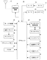
図1を参照して、携帯電話機10は、携帯端末の一種であり、コンピュータまたはCPUと呼ばれるプロセッサ24を含む。また、プロセッサ24には、無線通信回路14、A/D変換器16、D/A変換器20、キー入力装置26、表示ドライバ28、フラッシュメモリ32、RAM34、タッチパネル制御回路36、バックライト40、加速度センサ42、照度センサ44および近接センサ46などが接続される。
<First embodiment>
Referring to FIG. 1, a
無線通信回路14にはアンテナ12が接続される。A/D変換器16にはマイク18が接続され、D/A変換器20にはスピーカ22が接続される。表示ドライバ28にはディスプレイ30が接続される。タッチパネル制御回路36にはタッチパネル38が接続される。
An
プロセッサ24は携帯電話機10の全体制御を司る。RAM34は、プロセッサ24の作業領域(描画領域を含む)ないしバッファ領域として用いられる。フラッシュメモリ32には、携帯電話機10の文字、画像、音声、音および映像のようなコンテンツのデータが記録される。
The
A/D変換器16は、当該A/D変換器16に接続されたマイク18を通して入力される音声ないし音についてのアナログ音声信号を、デジタル音声信号に変換する。D/A変換器20は、デジタル音声信号をアナログ音声信号に変換(復号)して、図示しないアンプを介してスピーカ22に与える。したがって、アナログ音声信号に対応する音声ないし音がスピーカ22から出力される。また、プロセッサ24は、アンプの増幅率を制御することで、スピーカ22から出力される音声の音量を調整することができる。
The A /
キー入力装置26は操作部と呼ばれ、通話キー、機能キーおよび終話キーなどを含む。また、使用者が操作したキーの情報(キーデータ)はプロセッサ24に入力される。さらに、キー入力装置26に含まれる各キーが操作されると、クリック音が鳴る。したがって、使用者は、クリック音を聞くことで、キー操作に対する操作感を得ることができる。
The
表示ドライバ28は、プロセッサ24の指示の下、当該表示ドライバ28に接続されたディスプレイ30の表示を制御する。また、表示ドライバ28は表示する画像データを一時的に記憶するビデオメモリ(図示せず)を含む。
The
また、ディスプレイ30には、LEDを光源とするバックライト40が設けられている。そして、プロセッサ24は、照度センサ44の出力に基づいて、バックライト40を調光する。なお、バックライト40は、ディスプレイ30に含まれる表示パネルに対してエッジライト方式に基づいて設けられる。また、バックライト40の光源としては、LEDが採用されるが、他の実施例では冷陰極管などが採用されてもよい。そして、照度センサ44は、アレイ状に集積されたフォトダイオードなどを含み、携帯電話機10の周囲の照度を検出する。
The
タッチパネル38は、指などの物体が表面に接近して生じた電極間の静電容量の変化を検出する静電容量方式で、たとえば1本または複数本の指がタッチパネル38に触れたことを検出する。また、タッチパネル38は、ディスプレイ30の上に設けられ、その画面内で、任意の位置を指示するためのポインティングデバイスである。タッチパネル制御回路36は、タッチパネル38のタッチ範囲内で、押したり、撫でたり、触られたりするタッチ操作を検出し、そのタッチ操作の位置を示す座標のデータをプロセッサ24に出力する。つまり、使用者は、タッチパネル38の表面を指で、押したり、撫でたり、触れたりすることによって、操作の方向や図形などを携帯電話機10に入力することができる。
The
ここで、使用者がタッチパネル38の上面を指で触れる操作を「タッチ」と言うことにする。一方、タッチパネル38から指を離す操作を「リリース」と言うことにする。そして、「タッチ操作」には、上記したタッチおよびリリースなどが含まれる。
Here, an operation in which the user touches the upper surface of the
また、タッチによって示された座標を「タッチ点」(タッチ開始位置)、リリースによって示された座標を「リリース点」(タッチ終了位置)と言うことにする。 Also, the coordinates indicated by the touch are referred to as “touch points” (touch start position), and the coordinates indicated by the release are referred to as “release points” (touch end position).
なお、タッチ操作は指だけに限らず、導電体が先端に取り付けられたタッチペンなどによって行われてもよい。また、タッチパネル38の検出方式には、表面型の静電容量方式が採用されてもよいし、抵抗膜方式、超音波方式、赤外線方式および電磁誘導方式などであってもよい。
Note that the touch operation is not limited to a finger, and may be performed with a touch pen with a conductor attached to the tip. Further, as a detection method of the
加速度センサ42は、半導体式の3軸の加速度センサであり、図2(A),(B)に示す3軸の加速度データをプロセッサ24に出力する。また、プロセッサ24は、3軸の加速度データが示す値に対して逆三角関数を用いて、携帯電話機10の姿勢、つまり角度を算出する。そのため、加速度センサ42は、携帯電話機10の姿勢を検出する姿勢センサとして機能する。
The
近接センサ46は、図示は省略するが、発光素子である赤外LEDと受光素子であるフォトダイオードとから構成される。プロセッサ24は、フォトダイオードの出力の変化から、近接センサ46(当該携帯電話機10)に近接する物体(たとえば、使用者の顔など)の距離を算出する。具体的には、赤外LEDは、赤外線を発光し、フォトダイオードは、顔などで反射した赤外線を受光する。たとえば、フォトダイオードが使用者の顔から遠い場合には、赤外LEDが発光した赤外線はフォトダイオードによって受光されないが、近接センサ46に使用者の顔が近接すると、赤外LEDが発光した赤外線は顔に反射してフォトダイオードによって受光される。このように、フォトダイオードは近接センサ46が使用者の顔に近接している場合とそうでない場合とで赤外線の受光量が変化するため、プロセッサ24は、その受光量に基づいて、近接センサ46から対象までの距離を算出することができる。
Although not shown, the
なお、本実施例では、近接センサ46として、赤外線を利用する赤外線型の近接センサを用いるようにしてあるが、超音波の反射を利用する超音波型の近接センサなどを用いるようにしてもよい。また、近接センサ46は、通常状態では消費電力を抑えるために電源がオフにされており、必要に応じて電源がオンにされる。
In this embodiment, as the
無線通信回路14は、CDMA方式での無線通信を行うための回路である。たとえば、使用者がキー入力装置26を用いて電話発信(発呼)を指示すると、無線通信回路14は、プロセッサ24の指示の下、電話発信処理を実行し、アンテナ12を介して電話発信信号を出力する。電話発信信号は、基地局および通信網(図示せず)を経て相手の電話機に送信される。そして、相手の電話機において着信処理が行われると、通信可能状態が確立され、プロセッサ24は通話処理を実行する。
The
通常の通話処理について具体的に説明すると、相手の電話機から送られてきた変調音声信号はアンテナ12によって受信される。受信された変調音声信号には、無線通信回路14によって復調処理および復号処理が施される。そして、これらの処理によって得られた受話音声信号は、D/A変換器20によってアナログ音声信号に変換された後、スピーカ22から出力される。一方、マイク18を通して取り込まれた送話音声信号は、A/D変換器16によってデジタル音声信号に変換された後、プロセッサ24に与えられる。デジタル音声信号に変換された送話信号には、プロセッサ24の指示の下、無線通信回路14によって符号化処理および変調処理が施され、アンテナ12を介して出力される。したがって、変調音声信号は、基地局および通信網を介して相手の電話機に送信される。
The normal call processing will be described in detail. The modulated audio signal transmitted from the other party's telephone is received by the
また、相手の電話機からの電話発信信号がアンテナ12によって受信されると、無線通信回路14は、電話着信(着呼)をプロセッサ24に通知する。これに応じて、プロセッサ24は、表示ドライバ28を制御して、着信通知に記述された発信元情報(電話番号など)をディスプレイ30に表示する。また、これとほぼ同時に、プロセッサ24は、図示しないスピーカから着信音(着信メロディ、着信音声と言うこともある。)を出力させる。
When a telephone call signal from the other party's telephone is received by the
そして、使用者が通話キーを用いて応答操作を行うと、無線通信回路14は、プロセッサ24の指示の下、電話着信処理を実行する。さらに、通信可能状態が確立され、プロセッサ24は上述した通常の通話処理を実行する。
When the user performs a response operation using the call key, the
また、通話可能状態に移行した後に終話キーによって通話終了操作が行われると、プロセッサ24は、無線通信回路14を制御して、通話相手に通話終了信号を送信する。そして、通話終了信号の送信後、プロセッサ24は通話処理を終了する。また、先に通話相手から通話終了信号を受信した場合も、プロセッサ24は通話処理を終了する。さらに、通話相手によらず、移動通信網から通話終了信号を受信した場合も、プロセッサ24は通話処理を終了する。
Further, when a call end operation is performed with the call end key after shifting to the call ready state, the
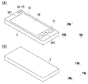
図2(A)は、携帯電話機10の表面の外観を示す外観図であり、図2(B)は携帯電話機10の裏面の外観を示す外観図である。図2(A)を参照して、携帯電話機10は、ストレート型の形状をしており、平面矩形の筐体Cを有する。図示しないマイク18は、筐体Cに内蔵され、内蔵されたマイク18に通じる開口OP2は筐体Cの縦方向一方の表面に設けられる。同じく、図示しないスピーカ22は、筐体Cに内蔵され、内蔵されたスピーカ22に通じる開口OP1は、筐体Cの縦方向他方の表面に設けられる。
FIG. 2A is an external view showing the external appearance of the front surface of the
キー入力装置26は、通話キー、機能キーおよび終話キーを含む。そして、これらのキーは筐体Cの表面に設けられる。ディスプレイ30は、表示面(モニタ画面)が筐体Cの表面から見えるように取り付けられる。また、ディスプレイ30の表示面の上にはタッチパネル38が設けられる。照度センサ44および近接センサ46は、センサ面が露出するように、筐体Cの右上角の表面に設けられる。なお、本実施例では、照度センサ44と近接センサ46とは隣り合うように設けられる。
The
たとえば、使用者は、ディスプレイ30に表示されたダイヤルキーに対して、タッチ操作を行うことで電話番号を入力し、通話キーによって音声発信操作を行う。そして、使用者は、通話が終了すると、終話キーによって通話終了操作を行う。また、使用者は、機能キーを操作することで、ディスプレイ30にメニュー画面を表示する。さらに、使用者は、ディスプレイ30に表示されたソフトキーおよびメニューに対してタッチ操作を行うことで、メニューの選択や確定を行う。
For example, the user inputs a telephone number by performing a touch operation on a dial key displayed on the
ここで、図2(A)に示すように、携帯電話機10の表面、つまりディスプレイ30の表示面が使用者によって認識できる状態を「上向き状態」状態と呼ぶ。一方、図2(B)に示すように、携帯電話機10の表面が使用者によって認識できない状態を「下向き状態」と呼ぶ。
Here, as shown in FIG. 2A, a state in which the surface of the
また、図2(A),(B)において、加速度センサ42は、携帯電話機10の縦方向(Y軸方向)、横方向(X軸方向)および厚み方向(Z軸方向)の3軸で各々の加速度を検出する。さらに、図2(A)に示す上向き状態の加速度データと、図2(B)に示す下向き状態の加速度データとは予め記憶されている。そして、加速度センサ42の加速度データが上向き状態の加速度データと略一致した場合、プロセッサ24は「上向き状態」と判断する。一方、加速度センサ42の加速度データが下向き状態の加速度データと略一致した場合、プロセッサ24は「下向き状態」と判断する。たとえば、この下向き状態としては重力加速度方向に略平行な方向(いわゆる鉛直方向)を挙げることができ、上向き方向としては重力加速度方向の逆方向に略平行な方向(いわゆる鉛直方向の逆方向)を挙げることができる。
2 (A) and 2 (B), the
なお、アンテナ12、無線通信回路14、A/D16、D/A20、プロセッサ24、表示ドライバ28、フラッシュメモリ32、RAM34、タッチパネル制御回路36、バックライト40および加速度センサ42は筐体Cに内蔵されているため、図2(A),(B)では図示されない。
The
図3は、照度センサ44の出力に基づいて輝度が調節されるディスプレイ30一例を示す図解図である。まず、図3(A)を参照して、たとえば携帯電話機10が待機状態の場合、消費電力を抑えるために、ディスプレイ30およびバックライト40の電源はオフにされる。そのため、ディスプレイ30の輝度は最も低い状態となる。
FIG. 3 is an illustrative view showing an example of the
次に、機能キーなどが操作されると、ディスプレイ30の電源がオンにされ、待ち受け画像が表示される。このとき、図3(B)に示すように携帯電話機10の周囲の照度が低い状態であれば、バックライト40は暗い状態に調光される。一方、図3(C)に示すように、携帯電話機10の周囲の照度が高い状態であれば、バックライト40が明るい状態に調光される。つまり、周囲が暗い状態では、バックライト40を暗くして、ディスプレイ30の輝度を下げることで、表示内容を見やすくする。一方、周囲が明るい状態では、バックライト40を明るくして、ディスプレイ30の輝度を上げることで、表示内容を見やすくする。
Next, when a function key or the like is operated, the power of the
ここで、本実施例では、携帯電話機10が利用される状況に応じてバックライト40の電源をオン/オフする。たとえば、図4(A)に示すように、携帯電話機10が下向き状態で机の上に伏せられると、使用者は携帯電話機10を利用していないと考えられるため、ディスプレイ30およびバックライト40の電源はオフにされる。つまり、加速度センサ42の出力に基づいて下向きの状態と判断され、かつ照度センサ44の出力に基づく照度値が閾値以下であれば、図3(A)に示すようにバックライト40の電源はオフにされる。
Here, in the present embodiment, the power of the
また、図4(B)に示すように、下向き状態で保持され、ディスプレイ30の表示内容が使用者によって確認されている状態であれば、バックライト40の明るさは調光される。つまり、下向き状態と判断されていたとしても、照度値が閾値よりも大きければ、照度センサ44の出力に基づいて、バックライト40は調光される。
Further, as shown in FIG. 4B, if the display content is held in the downward state and the display content of the
このように、2つのセンサを利用して、携帯電話機10が利用される状態を適切に判断し、バックライト40のオン/オフを制御できる。そのため、使用者に違和感を与えることなく、バックライト40の消費電力を抑えることができる。
In this way, it is possible to appropriately determine the state in which the
なお、本実施例では、バックライト40が点灯してから、タッチ操作およびキー操作がされない無操作状態が所定時間以上経過しても、消費電力を抑えるために、バックライト40の電源はオフにされる。
In the present embodiment, the
図5は、RAM34のメモリマップを示す図である。RAM34のメモリマップには、プログラム記憶領域302およびデータ記憶領域304が含まれる。また、プログラムおよびデータの一部は、フラッシュメモリ32から一度に全部または必要に応じて部分的かつ順次的に読み出され、RAM34に記憶されてからプロセッサ24によって処理される。
FIG. 5 is a diagram showing a memory map of the
プログラム記憶領域302には、携帯電話機10を動作させるためのプログラムが記憶されている。たとえば、携帯電話機10を動作させるためのプログラムには、バックライト制御プログラム310などが含まれる。バックライト制御プログラム310は、バックライト40の明るさや、電源のオン/オフを制御するためのプログラムである。
The
なお、図示は省略するが、携帯電話機10を動作させるためのプログラムには、音声着信状態を通知するためのプログラム、ディスプレイ30の表示を制御するためのプログラムも含まれる。
Although illustration is omitted, the program for operating the
続いて、データ記憶領域304には、加速度バッファ330、姿勢バッファ332、照度バッファ334、距離バッファ336などが設けられるとともに、点灯カウンタ338も設けられる。
Subsequently, in the
加速度バッファ330には、加速度センサ42から出力された3軸それぞれの加速度データが一時的に記憶される。姿勢バッファ332には、加速度バッファ330に格納された各軸の加速度データから算出された携帯電話機10の姿勢(上向き状態または下向き状態など)が一時的に記憶される。照度バッファ334は、照度センサ44の出力に基づいて得られた照度値が一時的に記憶される。距離バッファ336は、近接センサ46の出力に基づいて算出された距離値が一時的に記憶される。
The
点灯カウンタ338は、所定時間(たとえば、10秒)を計測するためのカウンタであり、初期化されるとカウントを開始する。そのため、点灯カウンタ338は点灯タイマとも呼ばれ、バックライト40の電源がオンにされ、点灯すると点灯カウンタ338は初期化されてカウントを開始する。
The
なお、図示は省略するが、データ記憶領域304には、待機状態で表示される画像データや、複数の照度値に対応するバックライト40の明るさが記録されるテーブルなどが記憶されると共に、携帯電話機10の動作に必要なカウンタや、フラグも設けられる。
Although not shown, the
プロセッサ24は、Android(登録商標)およびREXなどのLinux(登録商標)ベースのOSや、その他のOSの制御下で、図6に示すバックライト制御プログラムなどを含む複数のタスクを並列的に処理する。
The
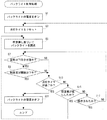
図6はバックライト制御処理のフロー図である。たとえば待機状態で機能キーが操作されると、プロセッサ24は、ステップS1でバックライト40の電源をオンにし、ステップS3で点灯タイマをリセットする。つまり、ステップS3では、バックライト40の電源がオンにされてからの時間の計測が開始される。続いて、ステップS5では、照度値に基づいてバックライト40が調光される。たとえば、周囲の照度が図3(A)に示す状態であれば、バックライト40の明るさが暗く調節される。
FIG. 6 is a flowchart of the backlight control process. For example, when the function key is operated in the standby state, the
続いて、ステップS7では、姿勢は下向き状態か否かを判断する。つまり、姿勢バッファ332に格納されている姿勢が、図2(B)に示す下向き状態を示しているか否かを判断する。なお、ステップS7の処理を実行するプロセッサ24は第1判断部として機能する。
Subsequently, in step S7, it is determined whether or not the posture is a downward state. That is, it is determined whether or not the posture stored in the
ステップS7で“NO”であれば、たとえば、携帯電話機10が図2(A)に示す上向き状態であれば、ステップS13に進む。また、ステップS7で“YES”であれば、つまり携帯電話機10が図2(B)に示す下向き状態でれば、ステップS9で照度値が閾値以下か否かを判断する。つまり、ステップS9では、携帯電話機10が机などの上に伏せられた状態か否かが判断される。なお、ステップS9の処理を実行するプロセッサ24は第2判断部および照度判断部として機能する。
If “NO” in the step S7, for example, if the
ステップS9で“YES”であれば、つまり携帯電話機10が図4(A)に示すように机の上に伏せられており、照度値が閾値以下であれば、ステップS11でバックライト40の電源をオフにして、バックライト制御処理を終了する。そして、ステップS11の処理を実行するプロセッサ24は制御部として機能する。
If “YES” in the step S9, that is, if the
一方、ステップS9で“NO”であれば、たとえば携帯電話機10が図4(B)に示す状態であり、照度値が閾値よりも大きければ、ステップS13で点灯タイマが満了したか否かを判断する。たとえば、ステップS13では、バックライト40が点灯してから、無操作状態で所定時間(たとえば10秒)が経過したか否かが判断される。ステップS13で“YES”であれば、つまり無操作状態のまま所定時間が経過すると、ステップS11に進む。
On the other hand, if “NO” in the step S9, for example, the
一方、ステップS13で“NO”であれば、つまり携帯電話機10が無操作状態のまま所定時間が経過していなければ、ステップS15で照度値が変化したか否かを判断する。つまり、プロセッサ24は、照度バッファ334に一時記憶された照度値を監視することで、携帯電話機10の周囲の照度が変化したかを判断する。ステップS15で“YES”であれば、つまり携帯電話機10の周囲の照度が変化した場合、ステップS5に戻る。つまり、変化した周囲の照度に合わせて、ディスプレイ30の輝度が再調整される。
On the other hand, if “NO” in the step S13, that is, if the predetermined time has not passed while the
一方、ステップS15で“NO”であれば、つまり携帯電話機10の周囲の照度が変化していなければ、ステップS17で操作されたか否かを判断する。たとえば、使用者によって、携帯電話機10に対してタッチ操作またはキー操作がされたか否かが判断される。ステップS17で“NO”であれば、つまり携帯電話機10に対して何も操作されていなければ、ステップS7に戻る。つまり、姿勢や、照度の変化などが再び判断される。一方、ステップS17で“YES”であれば、つまりタッチ操作またはキー操作がされると、ステップS3に戻る。つまり、使用者の操作に応じて、点灯タイマがリセットされ、ディスプレイ30の輝度が再調整される。
On the other hand, if “NO” in the step S15, that is, if the illuminance around the
<第2実施例>
第2実施例では、照度センサ44に代えて、近接センサ46によって携帯電話機10が机に伏せられた状態を判断する。なお、第2実施例の携帯電話機10は、第1実施例と略同じであるため、携帯電話機10の電気的な構成、外観およびRAM34のメモリマップの説明は省略する。
<Second embodiment>
In the second embodiment, instead of the
たとえば、携帯電話機10が図2(B)に示すように下向き状態にされると、近接センサ46の電源がオンにされる。そして、図4(A)に示すように、携帯電話機10が机の上に伏せられた場合、近接センサ46の出力に基づいて得られた距離値が閾値以下となるため、プロセッサ24は携帯電話機10が伏せられた状態であると判断する。そのため、第2実施例でも、携帯電話機10が図4(A)の状態になれば、バックライト40の電源はオフにされる。一方、図4(B)の状態では、距離値が閾値より大きくなるため、バックライト40は照度値に基づいて調光される。
For example, when the
このように、近接センサ46を利用しても、第1実施例と同様、携帯電話機10が利用される状態を適切に判断して、バックライト40を調光することができる。
As described above, even when the
また、近接センサ46を利用する必要があるときだけ、近接センサ46の電源をオンにすることで、消費電力を抑えることができる。
Further, power consumption can be suppressed by turning on the power of the
第2実施例のプロセッサ24は、AndroidおよびREXなどのLinuxベースのOSや、その他のOSの制御下で、図7に示す第2実施例のバックライト制御処理を含む複数のタスクを並列的に処理する。
The
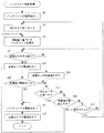
図7は、第2実施例のバックライト制御処理のフロー図である。なお、このフロー図では、図6に示すバックライト制御処理と同じステップには同一のステップ番号を付与し、詳細な説明は省略する。 FIG. 7 is a flowchart of the backlight control process of the second embodiment. In this flowchart, the same steps as those in the backlight control process shown in FIG. 6 are assigned the same step numbers, and detailed descriptions thereof are omitted.
プロセッサ24は、ステップS1でバックライト40の電源をオンにし、ステップS3で点灯タイマをリセットし、ステップS5で照度値に基づいてバックライト40を調光する。そして、ステップS7で携帯電話機10が下向き状態かを判断する。
The
ステップS7で“YES”であれば、つまり下向き状態と判断されると、ステップS21で近接センサ46の電源をオンにし、ステップS25に進む。つまり、携帯電話機10の表面が机の上に伏せられた状態かを判断するために、近接センサ46の電源がオンにされる。なお、ステップS21の処理を実行するプロセッサ24は電源制御部として機能する。また、ステップS7で“NO”であれば、ステップ23で近接センサ46の電源がオフにされる。
If “YES” in the step S7, that is, if it is determined to be in a downward state, the power of the
ステップS25では、距離値が閾値以下か否かを判断する。つまり、携帯電話機10が机などの上に伏せられ、距離バッファ336に格納された距離値が閾値以下となっているかが判断される。なお、ステップS25の処理を実行するプロセッサ24は近接判断部として機能する。
In step S25, it is determined whether the distance value is equal to or less than a threshold value. That is, it is determined whether the
ステップS25で“YES”であれば、たとえば携帯電話機10が図4(A)に示すように机の上に伏せられた状態で、距離バッファ336に格納された距離値が閾値以下であれば、ステップS11でバックライト40の電源をオフにし、ステップS27で近接センサ46の電源をオフにする。そして、ステップS27の処理が終了すれば、バックライト制御処理を終了する。
If “YES” in the step S25, the distance value stored in the
一方、ステップS25で“NO”であれば、つまり距離バッファ336に格納される距離値が閾値よりも大きければ、ステップS13で点灯タイマが満了か否かが判断される。ステップS13で“YES”であれば、つまり点灯タイマが満了すると、ステップS11に進む。一方、ステップS13で“NO”であれば、つまり点灯タイマが満了していなければ、ステップS15で照度値が変化したか否かが判断される。ステップS15で“YES”であれば、つまり照度値が変化すれば、ステップS5に戻る。一方、ステップS15で“NO”であれば、つまり照度値が変化しなければ、ステップS17で携帯電話機10が操作されたか否かが判断される。ステップS17で“NO”であれば、つまり携帯電話機10が操作されなければ、ステップS7に戻る。一方、ステップS17で“YES”であれば、つまり携帯電話機10に対して操作がされると、ステップS3に戻る。
On the other hand, if “NO” in the step S25, that is, if the distance value stored in the
以上のように、第1実施例および第2実施例では、2つのセンサを利用して、携帯電話機10が利用される状態を適切に判断し、バックライト40のオン/オフを制御できる。そのため、使用者に違和感を与えることなく、バックライト40の消費電力を抑えることができる。
As described above, in the first embodiment and the second embodiment, it is possible to appropriately determine the state in which the
なお、第1実施例および第2実施例では、照度センサ44または近接センサ46を利用して、ディスプレイ30の表示面の近くに机などが存在している状態を判断することができる。そのため、これらのセンサは「物体検出センサ」として機能する。
In the first and second embodiments, the
また、第1実施例および第2実施例では、照度センサ44および近接センサ46が共に搭載される例を説明したが、他の実施例の携帯電話機10は、これらのうちいずれか片方だけを搭載するようにしてもよい。
In the first embodiment and the second embodiment, the example in which the
また、本実施例では、携帯電話機10の姿勢を検出するために、加速度センサ42を利用したが、他の実施例ではジャイロセンサを利用して姿勢が検出されてもよい。
In this embodiment, the
また、携帯電話機10の通信方式はCDMA方式であるが、LTE(Long Term Evolution)方式、W−CDMA方式、GSM方式、TDMA方式、FDMA方式およびPHS方式などが採用されてもよい。
The communication system of the
また、本実施例で用いられた複数のプログラムは、データ配信用のサーバのHDDに記憶され、ネットワークを介して携帯電話機10に配信されてもよい。また、CD,DVD,BD(Blu−ray Disc)などの光学ディスク、USBメモリおよびメモリカードなどの記憶媒体に複数のプログラムを記憶させた状態で、その記憶媒体が販売または配布されてもよい。そして、上記したサーバや記憶媒体などを通じてダウンロードされた、複数のプログラムが本実施例と同等の構成の携帯電話機にインストールされた場合、本実施例と同等の効果が得られる。
Further, the plurality of programs used in this embodiment may be stored in the HDD of the data distribution server and distributed to the
さらに、本実施例は、携帯電話機10のみに限らず、いわゆるスマートフォンおよびPDAなどに適用されてもよい。
Furthermore, the present embodiment is not limited to the
そして、本明細書中で挙げた、所定時間などの具体的な数値は、いずれも単なる一例であり、製品の仕様などの必要に応じて適宜変更可能である。 The specific numerical values such as the predetermined time given in the present specification are merely examples, and can be appropriately changed according to the specifications of the product.
10 … 携帯電話機
12 … アンテナ
14 … 無線通信回路
24 … プロセッサ
26 … キー入力装置
34 … RAM
40 … バックライト
42 … 加速度センサ
44 … 照度センサ
46 … 近接センサ
DESCRIPTION OF
40 ...
Claims (6)
姿勢を検出する姿勢センサ、
前記姿勢センサの出力に基づいて、前記携帯端末が下向きの状態かを判断する第1判断部、
前記ディスプレイの近傍に設けられ、近くに存在する物体を検出する物体検出センサ、
前記物体検出センサの出力に基づいて、前記ディスプレイの表示面の近くに物体が存在している状態かを判断する第2判断部、および
前記第1判断部によって前記携帯端末が下向きの状態であると判断され、かつ前記第2判断部によって前記ディスプレイの表示面の近くに物体が存在している状態であると判断されたとき、前記バックライトの電源をオフにする制御部を備える、携帯端末。 A portable terminal having a display and a backlight provided in the display, wherein the brightness of the display is adjusted by the backlight;
Posture sensor for detecting posture,
A first determination unit configured to determine whether the mobile terminal is in a downward state based on an output of the attitude sensor;
An object detection sensor that is provided in the vicinity of the display and detects an object existing nearby;
A second determination unit configured to determine whether an object is present near a display surface of the display based on an output of the object detection sensor; and the portable terminal is in a downward state by the first determination unit. And a control unit that turns off the backlight when it is determined by the second determination unit that an object is present near the display surface of the display. .
前記第2判断部は、前記照度センサによって検出された照度に基づいて、前記ディスプレイの表示面の近くに物体が存在している状態かを判断する照度判断部を含む、請求項1記載の携帯端末。 The object detection sensor includes an illuminance sensor that detects ambient illuminance,
2. The mobile phone according to claim 1, wherein the second determination unit includes an illuminance determination unit that determines whether an object is present near a display surface of the display based on the illuminance detected by the illuminance sensor. Terminal.
前記第2判断部は、前記近接センサの検出結果に基づいて、前記ディスプレイの表示面の近くに物体が存在している状態かを判断する近接判断部を含む、請求項1記載の携帯端末。 The object detection sensor includes a proximity sensor that detects an adjacent object,
The mobile terminal according to claim 1, wherein the second determination unit includes a proximity determination unit that determines whether an object is present near a display surface of the display based on a detection result of the proximity sensor.
前記姿勢センサの出力に基づいて、前記携帯端末が下向きの状態かを判断する第1判断部、
前記物体検出センサの出力に基づいて、前記ディスプレイの表示面の近くに物体が存在している状態かを判断する第2判断部、および
前記第1判断部によって前記携帯端末が下向きの状態であると判断され、かつ前記第2判断部によって前記ディスプレイの表示面の近くに物体が存在している状態であると判断されたとき、前記バックライトの電源をオフにする制御部として機能させる、バックライト制御プログラム。 A display, a backlight provided in the display, an attitude sensor for detecting an attitude, and an object detection sensor provided in the vicinity of the display for detecting an object existing in the vicinity; the brightness of the display is adjusted by the backlight; The handheld processor,
A first determination unit configured to determine whether the mobile terminal is in a downward state based on an output of the attitude sensor;
A second determination unit configured to determine whether an object is present near a display surface of the display based on an output of the object detection sensor; and the portable terminal is in a downward state by the first determination unit. And when the second determination unit determines that an object is present near the display surface of the display, the backlight functions as a control unit that turns off the backlight. Light control program.
前記姿勢センサの出力に基づいて、前記携帯端末が下向きの状態かを判断し、
前記物体検出センサの出力に基づいて、前記ディスプレイの表示面の近くに物体が存在している状態かを判断し、そして
前記携帯端末が下向きの状態であると判断され、かつ前記ディスプレイの表示面の近くに物体が存在している状態であると判断されたとき、前記バックライトの電源をオフにする、バックライト制御方法。 A display, a backlight provided in the display, an attitude sensor for detecting an attitude, and an object detection sensor provided in the vicinity of the display for detecting an object existing in the vicinity; the brightness of the display is adjusted by the backlight; A backlight control method for a portable terminal,
Based on the output of the attitude sensor, determine whether the mobile terminal is in a downward state,
Based on the output of the object detection sensor, it is determined whether an object exists near the display surface of the display, and it is determined that the portable terminal is in a downward state, and the display surface of the display The backlight control method of turning off the power of the backlight when it is determined that an object is present in the vicinity.
Priority Applications (1)
| Application Number | Priority Date | Filing Date | Title |
|---|---|---|---|
| JP2011129687A JP5688330B2 (en) | 2011-06-10 | 2011-06-10 | Portable terminal, backlight control program, and backlight control method |
Applications Claiming Priority (1)
| Application Number | Priority Date | Filing Date | Title |
|---|---|---|---|
| JP2011129687A JP5688330B2 (en) | 2011-06-10 | 2011-06-10 | Portable terminal, backlight control program, and backlight control method |
Publications (2)
| Publication Number | Publication Date |
|---|---|
| JP2012257129A true JP2012257129A (en) | 2012-12-27 |
| JP5688330B2 JP5688330B2 (en) | 2015-03-25 |
Family
ID=47528253
Family Applications (1)
| Application Number | Title | Priority Date | Filing Date |
|---|---|---|---|
| JP2011129687A Expired - Fee Related JP5688330B2 (en) | 2011-06-10 | 2011-06-10 | Portable terminal, backlight control program, and backlight control method |
Country Status (1)
| Country | Link |
|---|---|
| JP (1) | JP5688330B2 (en) |
Cited By (11)
| Publication number | Priority date | Publication date | Assignee | Title |
|---|---|---|---|---|
| CN103458110A (en) * | 2013-08-17 | 2013-12-18 | 广东欧珀移动通信有限公司 | Method and mobile terminal for adjusting display screen backlight in combination with acceleration sensor |
| JP2014207081A (en) * | 2013-04-11 | 2014-10-30 | 富士通株式会社 | Electronic equipment |
| WO2015105278A1 (en) * | 2014-01-07 | 2015-07-16 | 에스케이플래닛 주식회사 | System and method for compensating measured illumination and apparatus therefor |
| CN104883425A (en) * | 2015-06-03 | 2015-09-02 | 广东欧珀移动通信有限公司 | Method and device for backlight brightness control of mobile terminal display screen |
| JP2015226210A (en) * | 2014-05-28 | 2015-12-14 | 京セラ株式会社 | Portable terminal, camera control program and camera control method |
| WO2016051947A1 (en) * | 2014-09-29 | 2016-04-07 | シャープ株式会社 | Portable information terminal device |
| JP2016063304A (en) * | 2014-09-16 | 2016-04-25 | セイコーインスツル株式会社 | Communication system, electronic apparatus, communication method, and program |
| JP2016513400A (en) * | 2013-02-12 | 2016-05-12 | クアルコム,インコーポレイテッド | Speaker equalization for mobile devices |
| JP2016191568A (en) * | 2015-03-30 | 2016-11-10 | 京セラディスプレイ株式会社 | Proximity sensor device |
| CN108537013A (en) * | 2017-12-29 | 2018-09-14 | 广东欧珀移动通信有限公司 | Electronic device, screen locking control method and Related product |
| WO2021087964A1 (en) * | 2019-11-08 | 2021-05-14 | 深圳市欢太科技有限公司 | Method and apparatus for controlling touch control display screen, and touch control display screen and electronic device |
Families Citing this family (1)
| Publication number | Priority date | Publication date | Assignee | Title |
|---|---|---|---|---|
| KR20220103742A (en) | 2020-01-20 | 2022-07-22 | 엘지전자 주식회사 | Electronic device for displaying content and method for controlling the same |
Citations (5)
| Publication number | Priority date | Publication date | Assignee | Title |
|---|---|---|---|---|
| JP2000307719A (en) * | 1999-04-15 | 2000-11-02 | Nec Saitama Ltd | Mobile portable terminal |
| JP2002152370A (en) * | 2000-11-07 | 2002-05-24 | Matsushita Electric Ind Co Ltd | Portable telephone set |
| JP2006101331A (en) * | 2004-09-30 | 2006-04-13 | Sharp Corp | Mobile terminal having supply current control function for display unit |
| JP2010263560A (en) * | 2009-05-11 | 2010-11-18 | Nec Saitama Ltd | Cellular phone terminal, control method thereof and control program therefor |
| JP2012186628A (en) * | 2011-03-04 | 2012-09-27 | Nec Saitama Ltd | Mobile phone and method for control of state thereof |
-
2011
- 2011-06-10 JP JP2011129687A patent/JP5688330B2/en not_active Expired - Fee Related
Patent Citations (5)
| Publication number | Priority date | Publication date | Assignee | Title |
|---|---|---|---|---|
| JP2000307719A (en) * | 1999-04-15 | 2000-11-02 | Nec Saitama Ltd | Mobile portable terminal |
| JP2002152370A (en) * | 2000-11-07 | 2002-05-24 | Matsushita Electric Ind Co Ltd | Portable telephone set |
| JP2006101331A (en) * | 2004-09-30 | 2006-04-13 | Sharp Corp | Mobile terminal having supply current control function for display unit |
| JP2010263560A (en) * | 2009-05-11 | 2010-11-18 | Nec Saitama Ltd | Cellular phone terminal, control method thereof and control program therefor |
| JP2012186628A (en) * | 2011-03-04 | 2012-09-27 | Nec Saitama Ltd | Mobile phone and method for control of state thereof |
Cited By (15)
| Publication number | Priority date | Publication date | Assignee | Title |
|---|---|---|---|---|
| JP2016513400A (en) * | 2013-02-12 | 2016-05-12 | クアルコム,インコーポレイテッド | Speaker equalization for mobile devices |
| JP2014207081A (en) * | 2013-04-11 | 2014-10-30 | 富士通株式会社 | Electronic equipment |
| CN103458110A (en) * | 2013-08-17 | 2013-12-18 | 广东欧珀移动通信有限公司 | Method and mobile terminal for adjusting display screen backlight in combination with acceleration sensor |
| WO2015105278A1 (en) * | 2014-01-07 | 2015-07-16 | 에스케이플래닛 주식회사 | System and method for compensating measured illumination and apparatus therefor |
| KR101848044B1 (en) * | 2014-01-07 | 2018-04-11 | 에스케이테크엑스 주식회사 | System for compensating measured illumination, method of compensating measured illumination and apparatus for the same |
| JP2015226210A (en) * | 2014-05-28 | 2015-12-14 | 京セラ株式会社 | Portable terminal, camera control program and camera control method |
| JP2016063304A (en) * | 2014-09-16 | 2016-04-25 | セイコーインスツル株式会社 | Communication system, electronic apparatus, communication method, and program |
| JPWO2016051947A1 (en) * | 2014-09-29 | 2017-04-27 | シャープ株式会社 | Portable information terminal device |
| WO2016051947A1 (en) * | 2014-09-29 | 2016-04-07 | シャープ株式会社 | Portable information terminal device |
| JP2016191568A (en) * | 2015-03-30 | 2016-11-10 | 京セラディスプレイ株式会社 | Proximity sensor device |
| CN104883425A (en) * | 2015-06-03 | 2015-09-02 | 广东欧珀移动通信有限公司 | Method and device for backlight brightness control of mobile terminal display screen |
| CN108537013A (en) * | 2017-12-29 | 2018-09-14 | 广东欧珀移动通信有限公司 | Electronic device, screen locking control method and Related product |
| WO2021087964A1 (en) * | 2019-11-08 | 2021-05-14 | 深圳市欢太科技有限公司 | Method and apparatus for controlling touch control display screen, and touch control display screen and electronic device |
| CN114286974A (en) * | 2019-11-08 | 2022-04-05 | 深圳市欢太科技有限公司 | Method and device for controlling touch display screen, touch display screen and electronic equipment |
| CN114286974B (en) * | 2019-11-08 | 2023-01-06 | 深圳市欢太科技有限公司 | Method and device for controlling touch display screen, touch display screen and electronic equipment |
Also Published As
| Publication number | Publication date |
|---|---|
| JP5688330B2 (en) | 2015-03-25 |
Similar Documents
| Publication | Publication Date | Title |
|---|---|---|
| JP5688330B2 (en) | Portable terminal, backlight control program, and backlight control method | |
| US11011131B2 (en) | Off-screen control method determining signal intensity calibration value for filmed display screen | |
| JP6062175B2 (en) | Portable terminal, power saving control program, and power saving control method | |
| JP5805503B2 (en) | Portable terminal, display direction control program, and display direction control method | |
| JP5694719B2 (en) | Mobile terminal, unlocking program, and unlocking method | |
| EP2887288A1 (en) | Message reminding method, device and electronic device | |
| CN109271014B (en) | Method and equipment for adjusting screen brightness | |
| WO2014084224A1 (en) | Electronic device and line-of-sight input method | |
| JP5743847B2 (en) | Mobile terminal and low sensitivity area setting program | |
| JP5825771B2 (en) | Mobile terminal, screen direction control program, and screen direction control method | |
| CN111458935A (en) | Display panel and terminal | |
| JP2012095069A (en) | Portable terminal, lock state control program and lock state control method | |
| WO2020082954A1 (en) | Terminal apparatus housing and mobile terminal | |
| JP6122355B2 (en) | Mobile terminal device | |
| JP2014064222A (en) | Mobile terminal, brightness control program, and brightness control method | |
| WO2020082955A1 (en) | Terminal device housing and mobile terminal | |
| CN109348016B (en) | Display screen, display control method and terminal equipment | |
| CN110442261A (en) | Electronic equipment and its touch control operation detection method | |
| CN109144462B (en) | Sound production control method and device, electronic device and computer readable medium | |
| JP5922460B2 (en) | Communication terminal, communication control program, and communication control method | |
| CN112202966B (en) | Communication information notification method and device and computer readable storage medium | |
| EP3668066A1 (en) | Casing assembly and terminal | |
| WO2019041129A1 (en) | Method for controlling lamp on terminal, terminal and computer-readable medium | |
| US20200348839A1 (en) | Man-Machine Interaction Method and Electronic Device | |
| WO2017166209A1 (en) | Method and device for configuring untouchable area, electronic device, display interface, and storage medium |
Legal Events
| Date | Code | Title | Description |
|---|---|---|---|
| A621 | Written request for application examination |
Free format text: JAPANESE INTERMEDIATE CODE: A621 Effective date: 20140210 |
|
| A977 | Report on retrieval |
Free format text: JAPANESE INTERMEDIATE CODE: A971007 Effective date: 20141024 |
|
| A131 | Notification of reasons for refusal |
Free format text: JAPANESE INTERMEDIATE CODE: A131 Effective date: 20141028 |
|
| A521 | Request for written amendment filed |
Free format text: JAPANESE INTERMEDIATE CODE: A523 Effective date: 20141224 |
|
| TRDD | Decision of grant or rejection written | ||
| A01 | Written decision to grant a patent or to grant a registration (utility model) |
Free format text: JAPANESE INTERMEDIATE CODE: A01 Effective date: 20150120 |
|
| A61 | First payment of annual fees (during grant procedure) |
Free format text: JAPANESE INTERMEDIATE CODE: A61 Effective date: 20150126 |
|
| R150 | Certificate of patent or registration of utility model |
Ref document number: 5688330 Country of ref document: JP Free format text: JAPANESE INTERMEDIATE CODE: R150 |
|
| LAPS | Cancellation because of no payment of annual fees |