JP2012256720A - Electronic apparatus and cover member used for it - Google Patents

Electronic apparatus and cover member used for it Download PDF

Info

Publication number
JP2012256720A
JP2012256720A JP2011128966A JP2011128966A JP2012256720A JP 2012256720 A JP2012256720 A JP 2012256720A JP 2011128966 A JP2011128966 A JP 2011128966A JP 2011128966 A JP2011128966 A JP 2011128966A JP 2012256720 A JP2012256720 A JP 2012256720A
Authority
JP
Japan
Prior art keywords
rib
cover member
wall
wall portion
tip
Prior art date
Legal status (The legal status is an assumption and is not a legal conclusion. Google has not performed a legal analysis and makes no representation as to the accuracy of the status listed.)
Withdrawn
Application number
JP2011128966A
Other languages
Japanese (ja)
Inventor
Naoto Komine
尚登 小嶺
Takashi Kawamura
崇 川村
Current Assignee (The listed assignees may be inaccurate. Google has not performed a legal analysis and makes no representation or warranty as to the accuracy of the list.)
Shin Etsu Polymer Co Ltd
Shin Etsu Chemical Co Ltd
Original Assignee
Shin Etsu Polymer Co Ltd
Shin Etsu Chemical Co Ltd
Priority date (The priority date is an assumption and is not a legal conclusion. Google has not performed a legal analysis and makes no representation as to the accuracy of the date listed.)
Filing date
Publication date
Application filed by Shin Etsu Polymer Co Ltd, Shin Etsu Chemical Co Ltd filed Critical Shin Etsu Polymer Co Ltd
Priority to JP2011128966A priority Critical patent/JP2012256720A/en
Publication of JP2012256720A publication Critical patent/JP2012256720A/en
Withdrawn legal-status Critical Current

Links

Images

Abstract

PROBLEM TO BE SOLVED: To provide an electronic apparatus with high waterproofness, in which a cover member can be easily mounted to a main body, and a cover member used for it.SOLUTION: An electronic apparatus 1 has a case member 2 with a housing part 3 opened for housing a housed object 1a, and a detachable cover member 10 to cover the opening of the case member 2. One of the case member 2 and the cover member 10 has a rib 12 projecting toward the other member, and the other member has a closed-loop like elastic member 6 on an outer periphery of the housing part 3. The elastic member 6 has two walls 7 provided in an inward and outward direction of a closed loop. Tips of the two walls 7 separate from each other with a gap smaller than the width of the rib 12, extend inward, and are deformed to be wound during inserting the rib 12.

Description

本発明は、電子機器およびそれに用いるカバー部材に関する。   The present invention relates to an electronic device and a cover member used therefor.

近年、携帯電話等の電子機器において、防水機能等が求められる場合がある。電子機器に防水機能を付与するには、少なくとも、本体に被収納物を収納するための収納部を覆うカバー部材と収納部との隙間から水が入りこまないようにする必要がある。たとえば、電池収納部へ水が入り込まないようにするために、電池収納部を覆うカバー部材に弾性体を有する環状の突起部を備え、電池収納部の外周にその弾性体が圧入される溝を備える構造が知られている(例えば、特許文献1を参照)。   In recent years, a waterproof function or the like may be required in an electronic device such as a mobile phone. In order to provide a waterproof function to an electronic device, it is necessary to prevent water from entering through a gap between at least a cover member that covers a storage unit for storing an object to be stored in the main body and the storage unit. For example, in order to prevent water from entering the battery housing portion, the cover member that covers the battery housing portion is provided with an annular protrusion having an elastic body, and a groove into which the elastic body is press-fitted on the outer periphery of the battery housing portion. The structure provided is known (for example, refer patent document 1).

特開2008−288174JP 2008-288174 A

特許文献1に開示される構造によれば、弾性体を有する突起部が溝に挿入されることで、弾性体と溝の内側とが密着し、外部から収納部への水の浸入を防ぐことができる。しかし、突起部を被覆する弾性体は、溝を形成する樹脂表面に対して難滑性を呈し、溝に挿入し難いという問題がある。特に、カバー部材の突起部と溝との間の寸法誤差が大きい場合には、弾性体を溝内に挿入することが、さらに困難になる。突起部が溝に不完全に挿入された状態は、防水性能の低下を招くので好ましくない。   According to the structure disclosed in Patent Document 1, the protrusion having the elastic body is inserted into the groove, so that the elastic body and the inside of the groove are in close contact with each other, preventing water from entering the storage portion from the outside. Can do. However, the elastic body that covers the protrusions has a problem that it is difficult to insert into the groove because it exhibits slipperiness with respect to the resin surface forming the groove. In particular, when the dimensional error between the protrusion of the cover member and the groove is large, it becomes more difficult to insert the elastic body into the groove. A state in which the protruding portion is incompletely inserted into the groove is not preferable because the waterproof performance is deteriorated.

本発明は、かかる問題を解消すべくなされたものであって、カバー部材を本体に容易に装着でき、かつ高い防水性を実現することのできる電子機器およびそれに用いるカバー部材を提供することを目的とする。   The present invention has been made to solve such a problem, and an object of the present invention is to provide an electronic device that can be easily attached to a main body and that can realize high waterproofness, and a cover member used therefor. And

上記目的を達成するため、本発明の一実施の形態は、被収納物を収納するための収納部を開口して備えるケース部材と、ケース部材の開口部を覆うように着脱可能なカバー部材と、を有し、ケース部材およびカバー部材の内の一方の部材は、他方の部材へ突出するリブを備え、他方の部材は、収納部の外周囲に、閉ループ状の弾性部材を備え、弾性部材は、閉ループの内外方向に設けられる2つの壁部を有し、2つの壁部の先端部は、リブよりも小さい間隙にて開口すると共に、互いに内側に向かって延出し、リブの挿入時に巻回するように変形する電子機器としている。   In order to achieve the above object, an embodiment of the present invention includes a case member provided with an opening for storing an object to be stored, and a cover member removable to cover the opening of the case member. One member of the case member and the cover member includes a rib protruding to the other member, and the other member includes a closed loop elastic member around the outer periphery of the storage portion. Has two wall portions provided in the inner and outer directions of the closed loop, and the tip portions of the two wall portions open at a gap smaller than the ribs and extend inward from each other, and are wound when the rib is inserted. The electronic device is deformed so as to rotate.

また、2つの壁部の先端部を除く間隙は、リブの幅よりも大きいのが好ましい場合もある。   In some cases, it is preferable that the gap excluding the tip portions of the two wall portions is larger than the width of the rib.

さらに、壁部の先端部の厚みは、根元部の厚みよりも小さいのが好ましい場合もある。   Furthermore, it may be preferable that the thickness of the tip of the wall is smaller than the thickness of the base.

本発明の別の一実施の形態は、被収納物を収納するための収納部を開口して備える電子機器のケース部材に対して、収納部の開口部を覆うように着脱可能に備えるカバー部材であって、収納部の外周囲に形成されるリブと対向する位置に、閉ループ状の弾性部材を備え、弾性部材は、閉ループの内外方向に設けられる2つの壁部を有し、2つの壁部の先端部は、リブよりも小さい間隙にて開口すると共に、互いに内側に向かって延出し、リブの挿入時に巻回するように変形するカバー部材としている。   Another embodiment of the present invention is a cover member that is detachably provided so as to cover an opening of a storage unit with respect to a case member of an electronic device provided with an opening for storing a storage object. A closed loop elastic member is provided at a position facing a rib formed on the outer periphery of the storage portion, and the elastic member has two wall portions provided in the inner and outer directions of the closed loop. The tip of each part is a cover member that opens at a gap smaller than that of the ribs, extends toward the inside, and is deformed so as to be wound when the rib is inserted.

また、2つの壁部の先端部を除く間隙は、リブの幅よりも大きいのが好ましい場合もある。   In some cases, it is preferable that the gap excluding the tip portions of the two wall portions is larger than the width of the rib.

壁部の先端部の厚みは、その根元部の厚みよりも小さいのが好ましい場合もある。   In some cases, the thickness of the tip of the wall is preferably smaller than the thickness of the base.

本発明によれば、カバー部材を本体に容易に装着でき、かつ高い防水性を実現することができる。   According to the present invention, the cover member can be easily attached to the main body, and high waterproofness can be realized.

本発明の実施の形態に係る電子機器の一例である携帯電話機を、その操作面側から見た斜視図である。It is the perspective view which looked at the mobile telephone which is an example of the electronic device which concerns on embodiment of this invention from the operation surface side. 図1に示す携帯電話機を、その背面側から見た分解斜視図である。It is the disassembled perspective view which looked at the mobile telephone shown in FIG. 1 from the back side. 図2に示すカバー部材を、被収納物に対向する面側から見た斜視図である。It is the perspective view which looked at the cover member shown in FIG. 2 from the surface side which opposes a to-be-contained object. 図1に示す携帯電話機を、ケース部材と、カバー部材とに分離して示すA−A線断面図である。FIG. 2 is a cross-sectional view of the mobile phone shown in FIG. 1 taken along the line AA separately showing a case member and a cover member. 図1に示す携帯電話機のA−A線断面図である。It is AA sectional view taken on the line of the mobile phone shown in FIG. 図4のBで示す部分について、リブの押し込み量と弾性部材との状態を拡大して示す拡大断面図である。It is an expanded sectional view which expands and shows the pushing amount of a rib, and the state of an elastic member about the part shown by B of FIG. 弾性部材の変形例における図4のBと同様の領域を示す拡大断面図である。It is an expanded sectional view which shows the area | region similar to B of FIG. 4 in the modification of an elastic member. 弾性部材の別の変形例における図4のBと同様の領域を示す拡大断面図である。It is an expanded sectional view which shows the area | region similar to B of FIG. 4 in another modification of an elastic member. 弾性部材の別の変形例における図4のBと同様の領域を示す拡大断面図である。It is an expanded sectional view which shows the area | region similar to B of FIG. 4 in another modification of an elastic member. 弾性部材の別の変形例における図4のBと同様の領域を示す拡大断面図である。It is an expanded sectional view which shows the area | region similar to B of FIG. 4 in another modification of an elastic member. 本発明の変形例1に係る携帯電話機における図5と同様の領域を示すA−A線断面図である。FIG. 6 is a cross-sectional view taken along line AA showing a region similar to FIG. 5 in the mobile phone according to the first modification of the present invention. 本発明の変形例2に係る携帯電話機における図5と同様の領域を示すA−A線断面図である。FIG. 6 is a cross-sectional view taken along line AA showing a region similar to FIG. 5 in a mobile phone according to Modification 2 of the present invention.

次に、本発明の電子機器およびそれに用いるカバー部材の各実施の形態について、図面を参照しながら説明する。なお、以下、電子機器の実施の形態を説明する中で、カバー部材の実施の形態についても説明する。   Next, each embodiment of the electronic device of the present invention and the cover member used therefor will be described with reference to the drawings. In the following description of the embodiment of the electronic apparatus, the embodiment of the cover member will also be described.

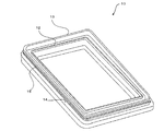
図1は、本発明の実施の形態に係る電子機器の一例である携帯電話機1を、その操作面側から見た斜視図である。   FIG. 1 is a perspective view of a mobile phone 1 which is an example of an electronic apparatus according to an embodiment of the present invention, as viewed from the operation surface side.

本発明の実施の形態に係る電子機器の一例である携帯電話機1は、薄い略直方体形状を有する。また、携帯電話機1は、ケース部材2側に表示部等を露出し、ケース部材2の操作面と逆側(以後、「背面側」という。)に、カバー部材10を着脱可能に備える。ケース部材2およびカバー部材10は、共に、携帯電話機1の筺体の一部を構成することから、同じ部材から構成されるのが好ましい。なお、以後の説明において、操作面から背面への方向を高さ方向という。   A mobile phone 1 which is an example of an electronic apparatus according to an embodiment of the present invention has a thin, substantially rectangular parallelepiped shape. In addition, the mobile phone 1 has a display unit or the like exposed on the case member 2 side, and a cover member 10 is detachably provided on the side opposite to the operation surface of the case member 2 (hereinafter referred to as “back side”). Since the case member 2 and the cover member 10 together constitute a part of the casing of the mobile phone 1, it is preferable that the case member 2 and the cover member 10 are composed of the same member. In the following description, the direction from the operation surface to the back surface is referred to as the height direction.

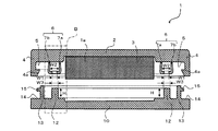
図2は、図1に示す携帯電話機1を、その背面側から見た分解斜視図である。図3は、図2に示すカバー部材10を、被収納物1aに対向する面側から見た斜視図である。図4は、図1に示す携帯電話機1を、ケース部材2と、カバー部材10とに分離して示すA−A線断面図である。図5は、図1に示す携帯電話機1のA−A線断面図である。なお、図4およびそれ以後の断面図では、見易さを考慮して、各部材の厚さの比率を実際の比率と変えて図示している。また、被収納物1aは、薄い略直方体の形態として図示している。   FIG. 2 is an exploded perspective view of the mobile phone 1 shown in FIG. 1 as viewed from the back side. FIG. 3 is a perspective view of the cover member 10 shown in FIG. 2 as viewed from the surface facing the object to be stored 1a. FIG. 4 is a cross-sectional view taken along line AA, showing the mobile phone 1 shown in FIG. 1 separated into a case member 2 and a cover member 10. FIG. 5 is a cross-sectional view taken along line AA of the mobile phone 1 shown in FIG. In FIG. 4 and subsequent cross-sectional views, the thickness ratio of each member is changed from the actual ratio in consideration of easy viewing. Moreover, the to-be-contained object 1a is illustrated as a thin substantially rectangular parallelepiped form.

ケース部材2は、被収納物1aを収納する収納部3を開口して備える。被収納物1aは、本実施の形態において、薄い略直方体である。被収納物1aとしては、たとえば、携帯電話機1の制御部、記憶部、電池、メモリーディスクあるいはPCB等が挙げられる。なお、被収納物1aは、収納部3から脱落しないように固定されてもよいし、収納部3とカバー部材10とに挟まれることにより保持されてもよい。   The case member 2 is provided with an opening of a storage portion 3 that stores the storage object 1a. The to-be-contained object 1a is a thin substantially rectangular parallelepiped in this Embodiment. Examples of the objects to be stored 1a include a control unit, a storage unit, a battery, a memory disk, or a PCB of the mobile phone 1. The storage object 1 a may be fixed so as not to drop out of the storage unit 3, or may be held by being sandwiched between the storage unit 3 and the cover member 10.

ケース部材2は、その外周に側壁4を有している。側壁4は、その内周面に、内周側に突出する係止爪4aを有している。また、ケース部材2は、側壁4の内側と収納部3との間にある平坦部5に、弾性部材6を有する。弾性部材6は、収納部3の外周囲に設けられる閉ループ状の部材である。弾性部材6は、接着剤等により、平坦部5に固着される。平坦部5は、弾性部材6を固着する位置の位置決めを容易にするために、弾性部材6を固着する位置に突起あるいは印(不図示)を有してもよい。   The case member 2 has a side wall 4 on its outer periphery. The side wall 4 has the latching claw 4a which protrudes to the inner peripheral side on the inner peripheral surface. The case member 2 has an elastic member 6 in a flat portion 5 between the inside of the side wall 4 and the storage portion 3. The elastic member 6 is a closed loop member provided on the outer periphery of the storage unit 3. The elastic member 6 is fixed to the flat portion 5 with an adhesive or the like. The flat portion 5 may have a protrusion or a mark (not shown) at a position where the elastic member 6 is fixed in order to facilitate positioning of the position where the elastic member 6 is fixed.

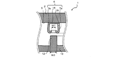
弾性部材6は、壁部として、内周側の第1の壁部7aと、第1の壁部7aの外側を囲むように配置される第2の壁部7bと、を有する。第1の壁部7aおよび第2の壁部7b(以後、第1の壁部7aと第2の壁部7bとの両方を指す場合には、「壁部7」という。)は、閉ループ状に形成されている。第1の壁部7aと第2の壁部7bとの各先端部の間隙は、内外方向の幅W1にて離間している。また、第1の壁部7aと第2の壁部7bとは、各先端部より根元に近い位置において、内外方向の幅W2(W2>W1)にて離間している。幅W2は、後述するリブ12の幅W3よりも大きいのが好ましい。ただし、幅W2がリブ12の幅W3と同一若しくは狭くても、リブ12の挿入時に壁部7が開くように変形容易であればよい。   The elastic member 6 includes a first wall portion 7a on the inner peripheral side and a second wall portion 7b disposed so as to surround the outside of the first wall portion 7a as wall portions. The first wall portion 7a and the second wall portion 7b (hereinafter referred to as “wall portion 7” when referring to both the first wall portion 7a and the second wall portion 7b) are in a closed loop shape. Is formed. The gap between the tip portions of the first wall portion 7a and the second wall portion 7b is separated by a width W1 in the inner and outer directions. The first wall portion 7a and the second wall portion 7b are separated by a width W2 (W2> W1) in the inner and outer directions at a position closer to the root than each tip portion. The width W2 is preferably larger than the width W3 of the rib 12 described later. However, even if the width W2 is the same as or narrower than the width W3 of the rib 12, it is only necessary that the wall portion 7 can be easily opened when the rib 12 is inserted.

壁部7の幅方向の厚さは、たとえば、0.2mm以上、より好ましくは、0.5mm以上である。壁部7の幅方向の厚さが0.2mm以上の場合、一般的な成形法により壁部7を成形しやすく、かつ壁部7の形状を保持可能である。なお、壁部7の先端部分の幅方向の厚さは、根元部分のそれよりも小さいのが好ましい。かかる形態により、壁部7の先端部分が変形しやすくなる一方、壁部7の剛性が高くなり、壁部7と後述するリブ12との間の封止力が向上する。   The thickness of the wall portion 7 in the width direction is, for example, 0.2 mm or more, and more preferably 0.5 mm or more. When the thickness of the wall portion 7 in the width direction is 0.2 mm or more, the wall portion 7 can be easily formed by a general forming method, and the shape of the wall portion 7 can be maintained. In addition, it is preferable that the thickness of the width direction of the front-end | tip part of the wall part 7 is smaller than that of a root part. With this configuration, the distal end portion of the wall portion 7 is easily deformed, while the rigidity of the wall portion 7 is increased, and the sealing force between the wall portion 7 and a rib 12 described later is improved.

壁部7は、柔軟性に富む弾性体にて主に形成される。たとえば、壁部7の好適な硬度は、JIS−A硬度にて90度以下、より好ましくは60度以下である。かかる硬度範囲では、後述するリブ12は、壁部7の先端部を内側に向けて変形させやすい。また、壁部7の先端部は、互いに内側に向かって延出しており、巻回しやすい構造となっている。したがって、リブ12が壁部7の先端部を押し下げると、壁部7の先端部は、巻回するように屈曲し、壁部7の対向しない面側が、リブ12の側面に接する。また、壁部7の形状を保持するために、壁部7の好適な硬度は、JIS−A硬度にて10度以上、さらに好適な硬度は30度以上である。   The wall portion 7 is mainly formed of a flexible elastic body. For example, the suitable hardness of the wall part 7 is 90 degrees or less in JIS-A hardness, More preferably, it is 60 degrees or less. In such a hardness range, the rib 12 to be described later is easily deformed with the front end portion of the wall portion 7 facing inward. Moreover, the front-end | tip part of the wall part 7 is mutually extended toward the inner side, and has a structure which is easy to wind. Therefore, when the rib 12 pushes down the distal end portion of the wall portion 7, the distal end portion of the wall portion 7 is bent so as to be wound, and the non-opposing surface side of the wall portion 7 is in contact with the side surface of the rib 12. Moreover, in order to maintain the shape of the wall part 7, the suitable hardness of the wall part 7 is 10 degree | times or more in JIS-A hardness, and a more suitable hardness is 30 degree | times or more.

また、壁部7は、カバー部材10の着脱動作を繰り返す場合に、後述するリブ12により変形と開放とを繰り返すため、その形状をある程度保持可能な材料から構成されるのが好ましい。たとえば、JIS K 6262に準拠した測定法より測定された圧縮永久歪(CS)が50%以下、好ましくは20%以下であることが好ましい。CSが50%以下の場合、第1の壁部7aおよび第2の壁部7bは、数回の変形により、元の形状に復元しやすく、寸法精度が維持できるため、十分に高い防水性能を発揮しやすい。   Moreover, when repeating the attachment / detachment operation | movement of the cover member 10, since the wall part 7 repeats a deformation | transformation and opening | release by the rib 12 mentioned later, it is preferable to comprise the material which can hold | maintain the shape to some extent. For example, the compression set (CS) measured by a measurement method based on JIS K 6262 is 50% or less, preferably 20% or less. When CS is 50% or less, the first wall portion 7a and the second wall portion 7b can be easily restored to their original shapes and maintain dimensional accuracy by deformation several times. Easy to demonstrate.

壁部7を構成する材料としては、例えば、ポリエステル系、ポリウレタン系あるいはポリオレフィン系等の熱可塑性エラストマー、または、天然ゴム、イソプレンゴム、ブタジエンゴム、クロロプレンゴム、アクリロニトリル‐ブタジエンゴム(NBR)、ブチルゴム、エチレンプロピレンジエンゴム(EPDM)、アクリルゴム、シリコーンゴムあるいはフッ素ゴム等の熱硬化性エラストマーを好適に用いることができる。その中でも、シール材として必要な特性、たとえば、耐熱性、耐寒性、耐候性、耐薬品性および圧縮永久歪等に優れ、比較的安価なシリコーンゴムを特に好適に用いることができる。   Examples of the material constituting the wall portion 7 include thermoplastic elastomers such as polyester, polyurethane or polyolefin, or natural rubber, isoprene rubber, butadiene rubber, chloroprene rubber, acrylonitrile-butadiene rubber (NBR), butyl rubber, Thermosetting elastomers such as ethylene propylene diene rubber (EPDM), acrylic rubber, silicone rubber or fluoro rubber can be suitably used. Among them, a silicone rubber that is excellent in characteristics necessary for a sealing material, such as heat resistance, cold resistance, weather resistance, chemical resistance, compression set, and the like, and relatively inexpensive can be used particularly suitably.

ケース部材2およびカバー部材10は、たとえば、薄いトレイ形状の成型体である。ケース部材2およびカバー部材10は、成形性および加工性等の理由から、ABS樹脂、ポリカーボネート樹脂、ポリアミド樹脂あるいはPBT樹脂等の熱可塑性樹脂、または、それらのアロイ等から好適に構成される。さらに、それらの樹脂にガラスファイバー等を混合してもよい。カバー部材10は、収納部3に収納された被収納物1aを覆うように、ケース部材2に装着される。ケース部材2およびカバー部材10は、カバー部材10がケース部材2に装着された際に、それらの両側面が面一になるように構成されている。   The case member 2 and the cover member 10 are thin tray-shaped molded bodies, for example. The case member 2 and the cover member 10 are preferably composed of a thermoplastic resin such as ABS resin, polycarbonate resin, polyamide resin or PBT resin, or an alloy thereof for reasons such as moldability and workability. Furthermore, you may mix glass fiber etc. in those resin. The cover member 10 is attached to the case member 2 so as to cover the storage object 1 a stored in the storage unit 3. The case member 2 and the cover member 10 are configured such that, when the cover member 10 is attached to the case member 2, both side surfaces thereof are flush with each other.

カバー部材10は、ケース部材2に装着した場合に、ケース部材2側へ突出するリブ12を有する。リブ12は、カバー部材10をケース部材2に取り付けた際に、第1の壁部7aと第2の壁部7bとの間隙に対向する位置に設けられている。また、カバー部材10は、リブ12の外周を取り囲む外壁13を有する。外壁13は、リブ12と離間して設けられている。さらに、カバー部材10は、外壁13の外周に、外壁13より低い段差をもって略水平な外周面14を有する。外壁13の外周側の面は、その外周を取り囲むように、外周側に突出する係止用突起15を有している。   The cover member 10 has a rib 12 that protrudes toward the case member 2 when the cover member 10 is attached to the case member 2. The rib 12 is provided at a position facing the gap between the first wall portion 7a and the second wall portion 7b when the cover member 10 is attached to the case member 2. The cover member 10 has an outer wall 13 that surrounds the outer periphery of the rib 12. The outer wall 13 is provided away from the rib 12. Further, the cover member 10 has a substantially horizontal outer peripheral surface 14 with a step difference lower than that of the outer wall 13 on the outer periphery of the outer wall 13. The outer peripheral surface of the outer wall 13 has a locking projection 15 protruding toward the outer peripheral side so as to surround the outer periphery.

カバー部材10をケース部材2に取り付けると、ケース部材2およびカバー部材10は、カバー部材10の係止用突起15がケース部材2の係止爪4aに引っ掛かることにより係止される。また、カバー部材10をケース部材2に取り付けると、リブ12は、第1の壁部7aと第2の壁部7bとの間隙に挿入される。   When the cover member 10 is attached to the case member 2, the case member 2 and the cover member 10 are locked by the locking protrusions 15 of the cover member 10 being hooked on the locking claws 4 a of the case member 2. When the cover member 10 is attached to the case member 2, the rib 12 is inserted into the gap between the first wall portion 7a and the second wall portion 7b.

リブ12は、高さがHおよび幅がW3の閉ループ状にて、カバー部材10に設けられている。リブ12は、その断面が略直方体であって、その先端側および根元側の両幅とも、強度や成形性を考慮して、0.2mm以上であるのが好ましい。リブ12は、壁部7の先端部を押し込んで、壁部7を先端側から巻回するように変形させるのに十分な高さを必要する。リブ12の好適な高さHは、0.5mm以上、より好ましくは1.0mm以上である。なお、リブ12は、カバー部材10と別体に固定されても、あるいは一体的に形成されてもよい。さらに、リブ12の先端部は、平面あるいは曲面であるのがより好ましい。   The rib 12 is provided on the cover member 10 in a closed loop shape having a height H and a width W3. The cross section of the rib 12 is substantially a rectangular parallelepiped, and it is preferable that both the tip side and the base side have a width of 0.2 mm or more in consideration of strength and formability. The rib 12 needs to have a height sufficient to push in the distal end portion of the wall portion 7 and deform the wall portion 7 so as to be wound from the distal end side. The suitable height H of the rib 12 is 0.5 mm or more, more preferably 1.0 mm or more. The rib 12 may be fixed separately from the cover member 10 or may be formed integrally. Furthermore, it is more preferable that the tip portion of the rib 12 is a flat surface or a curved surface.

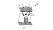
図6の(A)〜(C)は、図4のBで示す部分について、リブ12の押し込み量と弾性部材6との状態を拡大して示す拡大断面図である。   6 (A) to 6 (C) are enlarged cross-sectional views showing the pushing amount of the rib 12 and the state of the elastic member 6 in the portion indicated by B in FIG.

図6の(A)に示すように、第1の壁部7aと第2の壁部7bとの先端部は、互いに近づく方向に屈曲している。壁部7の先端部の間隙W1は、これと対向するリブ12の幅W3よりも小さい。カバー部材10をケース部材2に取り付けると、リブ12は、まず、図6の(B)に示すように、壁部7の先端側を、平坦部5側の空間に向けて押し込む。   As shown to (A) of FIG. 6, the front-end | tip part of the 1st wall part 7a and the 2nd wall part 7b is bent in the direction which mutually approaches. The gap W1 at the front end of the wall 7 is smaller than the width W3 of the rib 12 facing this. When the cover member 10 is attached to the case member 2, the rib 12 first pushes the front end side of the wall portion 7 toward the space on the flat portion 5 side as shown in FIG. 6B.

リブ12が壁部7の先端側を当該空間に向けてさらに押し込むと、図6の(C)に示すように、壁部7は、巻回するように変形する。リブ12の先端が、巻回した壁部7同士の間隙に挿入を続けていくと、壁部7の巻回回数が多くなり、壁部7にてリブ12を挟み込む力が徐々に強くなる。最終的に、壁部7は、リブ12の側面に密着する。したがって、カバー部材10をケース部材2に取り付け、リブ12が壁部7に挟まれた状態において、外部から浸入した水は、収納部3に浸入しにくくなる。   When the rib 12 further pushes the distal end side of the wall portion 7 toward the space, the wall portion 7 is deformed so as to be wound as shown in FIG. When the tip of the rib 12 continues to be inserted into the gap between the wound wall portions 7, the number of windings of the wall portion 7 increases, and the force for sandwiching the rib 12 at the wall portion 7 gradually increases. Finally, the wall portion 7 is in close contact with the side surface of the rib 12. Therefore, when the cover member 10 is attached to the case member 2 and the rib 12 is sandwiched between the wall portions 7, the water that has entered from the outside is less likely to enter the storage portion 3.

上述のような携帯電話機1においては、カバー部材10をケース部材2に取り付ける際、リブ12が壁部12の先端部に接触した初期段階には、先端部が容易に内側の空間内に変形するので、リブ12の挿入の抵抗は低い。その後、リブ12の挿入が進行するにしたがって、壁部7の先端部が巻回して太くなるため、リブ12の挿入抵抗が大きくなる。ついには、壁部7の先端側の巻回外周面が、リブ12をしっかりと挟み込み、リブ12に密着する。その結果、外部からの異物(水等)が収納部3の内部に入らないように、効果的に封止できる。このように、上述のような携帯電話機1においては、カバー部材10をケース部材2に容易に装着できることに加え、かつ、高い防水性を実現できる。   In the cellular phone 1 as described above, when the cover member 10 is attached to the case member 2, the tip portion easily deforms into the inner space at the initial stage when the rib 12 contacts the tip portion of the wall portion 12. Therefore, the insertion resistance of the rib 12 is low. Thereafter, as the insertion of the rib 12 proceeds, the tip end portion of the wall portion 7 is wound and thickened, so that the insertion resistance of the rib 12 increases. Eventually, the winding outer peripheral surface on the front end side of the wall portion 7 sandwiches the rib 12 firmly and comes into close contact with the rib 12. As a result, it is possible to effectively seal so that foreign matter (water or the like) from the outside does not enter the storage unit 3. As described above, in the mobile phone 1 as described above, the cover member 10 can be easily attached to the case member 2 and high waterproofness can be realized.

また、上述のように、壁部7の先端部が変形しやすいので、弾性部材6に滑り性を向上させるための被覆層を設ける必要はない。この結果、生産性の向上に加えて、製造コストの低減も可能である。ただし、壁部7は、耐異物付着性、滑り性および撥水性の少なくともいずれか1つを向上させる等のために、その表面に壁部7とは別の部材による被覆層を設けてもよい。その被覆層は、たとえば、フッ素含有樹脂により形成されていてもよい。あるいは、リブ12が弾性部材6に対して滑ってしまうことで壁部7が巻回しにくくなることを防止するため、壁部7に滑り性を低下させる被覆層等を設けてもよい。また、ケース部材2には、両方の壁部7を挟んで両側若しくはいずれか片側に、リブ12の挿入時に壁部7が過度に拡がるのを規制する延出部を設けても良い。延出部は、壁部7の外側面全部と固着されない限り、例えば、壁部7の変形容易な先端部を除く根元側の領域と固着される状態、壁部7の外側面に接する状態、あるいは壁部7の外側面と空間をあけた状態にて形成することができる。なお、延出部は、先端部の変形の障害にならないように、壁部7の先端部よりも低く形成される方が好ましい。   Moreover, since the front-end | tip part of the wall part 7 is easy to deform | transform as mentioned above, it is not necessary to provide the coating layer for improving slipperiness | lubricant in the elastic member 6. FIG. As a result, in addition to improving productivity, it is possible to reduce manufacturing costs. However, the wall portion 7 may be provided with a coating layer made of a member different from the wall portion 7 on the surface thereof in order to improve at least one of the adhesion to foreign matters, the slipperiness, and the water repellency. . The covering layer may be formed of, for example, a fluorine-containing resin. Or in order to prevent that the wall part 7 becomes difficult to wind by the rib 12 slipping with respect to the elastic member 6, you may provide the coating layer etc. which reduce slidability in the wall part 7. FIG. In addition, the case member 2 may be provided with an extending portion that restricts the wall portion 7 from excessively expanding when the rib 12 is inserted, on both sides or either one side of the wall portion 7. As long as the extension part is not fixed to the entire outer surface of the wall part 7, for example, a state in which the extension part is fixed to the base side area excluding the easily deformable tip part, a state in contact with the outer surface of the wall part 7, Or it can form in the state which opened the outer side surface of the wall part 7, and space. In addition, it is preferable that the extension portion is formed lower than the tip portion of the wall portion 7 so as not to obstruct deformation of the tip portion.

以上、本発明の電子機器およびそれに用いるカバー部材の好適な実施の形態を説明してきたが、本発明は、上述の実施の形態に限定されず、種々の変形を施して実施することができる。   As mentioned above, although preferred embodiment of the electronic device of this invention and the cover member used for it has been demonstrated, this invention is not limited to the above-mentioned embodiment, It can implement with various deformation | transformation.

例えば、上述の実施の形態では、電子機器として携帯電話機1を例示したが、携帯電話機1以外の電子機器にも応用可能であって、例えば、PDA、固定電話機、ホームオーディオ機器、車載用オーディオ機器、カーナビゲーション機器、バッテリーを搭載する電気自動車等の機器にも応用できる。また、上述の実施の形態では、収納部3への水の浸入を防止する構造を例示したが、上述の構造では、水以外の液体や埃等の、他の異物を防止することができる。   For example, in the above-described embodiment, the cellular phone 1 is exemplified as the electronic device. However, the cellular phone 1 can be applied to electronic devices other than the cellular phone 1, for example, a PDA, a fixed phone, a home audio device, an in-vehicle audio device. It can also be applied to devices such as car navigation devices and electric vehicles equipped with batteries. In the above-described embodiment, the structure that prevents water from entering the storage unit 3 is exemplified. However, in the above-described structure, other foreign matters such as liquid and dust other than water can be prevented.

また、上述の実施の形態では、収納部3は、背面側から見て、角が曲面の直方体としたが、このような形態に限らない。収納部3およびカバー部材10等の形状は、被収納物1aの形状により円形、あるいはその他の多角形等の形状であってもよい。   Further, in the above-described embodiment, the storage unit 3 is a rectangular parallelepiped with corners as viewed from the back side, but is not limited to such a form. The shapes of the storage unit 3 and the cover member 10 may be circular or other polygonal shapes depending on the shape of the storage object 1a.

また、上述の実施の形態では、ケース部材2が係止用爪4aを有し、カバー部材10が係止用突起15を有する形態としているが、このような形態に限らない。係止用突起15と係止爪4aとの引掛構造以外の構造により、カバー部材10とケース部材2とが固定されてもよい。たとえば、ケース部材2にカバー部材10をネジ止めしてもよい。   In the above-described embodiment, the case member 2 has the locking claw 4a and the cover member 10 has the locking protrusion 15. However, the present invention is not limited thereto. The cover member 10 and the case member 2 may be fixed by a structure other than the hooking structure of the locking protrusion 15 and the locking claw 4a. For example, the cover member 10 may be screwed to the case member 2.

図7〜10は、弾性部材6の変形例における図4のBと同様の領域を示す拡大断面図である。なお、以下の変形例においては、携帯電話機1と同じ構成要素については、同じ符号を用いて説明する。   7 to 10 are enlarged cross-sectional views showing the same region as B in FIG. 4 in the modified example of the elastic member 6. In the following modification, the same components as those of the mobile phone 1 will be described using the same reference numerals.

上述の実施の形態では、弾性部材6が有する第1の壁部7aおよび第2の壁部7bは、別々に平坦部5に対し立設しているが、このような形態に限らない。図7に示すように、第1の壁部7aと第2の壁部7bとは、その根元部に設けられた連接部分16により連接されていてもよい。   In the above-described embodiment, the first wall portion 7a and the second wall portion 7b of the elastic member 6 are separately provided with respect to the flat portion 5; however, the present invention is not limited to such a configuration. As shown in FIG. 7, the first wall portion 7a and the second wall portion 7b may be connected by a connecting portion 16 provided at the base portion thereof.

上述の実施の形態では、壁部7の根元部は、平坦部5に対し略垂直に立設しているが、このような形態に限らない。図8に示すように、弾性部材6は、第1の壁部7aと第2の壁部7bとが近づく方向に傾斜して形成されていても良い。かかる場合には、リブ12の挿入により、壁部7がリブ12から離れる方向に反りにくい。   In the above-described embodiment, the base portion of the wall portion 7 is erected substantially perpendicular to the flat portion 5, but is not limited to such a form. As shown in FIG. 8, the elastic member 6 may be formed to be inclined in a direction in which the first wall portion 7a and the second wall portion 7b approach each other. In such a case, the wall portion 7 is unlikely to warp in the direction away from the rib 12 due to the insertion of the rib 12.

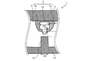
上述の実施の形態では、弾性部材6は、先端部の厚みと根元部の厚みとが略同一の壁部7を有しているが、このような形態に限らない。図9に示すように、弾性部材6は、先端部の厚みT2が根元部の厚みT1よりも小さい壁部7を有してもよい。かかる場合には、リブ12の挿入により、先端部が巻回しやすく、かつ、壁部7の根元部がリブ12から離れる方向に反りにくいため、リブ12と壁部7との密着を保つことができる。なお、先端部の厚みT2は、根元部の厚みT1より大きくすることもできる。特に、第1の壁部7aと第2の壁部7bとを挟むように延出部を形成している場合には、第1の壁部7aと第2の壁部7bとの間隙が過度に拡がらないので、根元部の厚みT1が先端部の厚みT2より小さくても良い。   In the above-described embodiment, the elastic member 6 has the wall portion 7 in which the thickness of the distal end portion and the thickness of the root portion are substantially the same, but it is not limited to such a form. As shown in FIG. 9, the elastic member 6 may have a wall portion 7 in which the thickness T2 of the tip portion is smaller than the thickness T1 of the root portion. In such a case, the insertion of the rib 12 facilitates winding of the distal end portion, and the base portion of the wall portion 7 is unlikely to warp in the direction away from the rib 12, so that the rib 12 and the wall portion 7 can be kept in close contact with each other. it can. Note that the thickness T2 of the tip portion can be larger than the thickness T1 of the root portion. In particular, when the extending part is formed so as to sandwich the first wall part 7a and the second wall part 7b, the gap between the first wall part 7a and the second wall part 7b is excessive. Therefore, the thickness T1 of the root portion may be smaller than the thickness T2 of the tip portion.

また、図10に示すように、壁部7は、平坦部5との間に脱気口19を有してもよい。特に、防水性を高める必要から、脱気口19は、収納部3側、すなわち内側の壁部7に形成されるのが好ましい。脱気口19を形成すると、リブ12により壁部7の先端部が押し下げられた際に、壁部7、リブ12および平坦部5により囲まれた空間にある空気を脱気口19からスムーズに排出できる。逆に、リブ12を壁部7から引き抜くと、脱気口19から当該空間に空気が流入する。このように、壁部7、リブ12および平坦部5により囲まれた空間が閉空間とならないので、リブ12を挿脱する際の挿入抵抗が小さい。なお、脱気口19は、壁部7と平坦部5との間の一部を非接着状態とすることで設けられてもよいし、壁部7を貫通する孔を設けることにより形成してもよい。なお、この変形例では、脱気口19は、高さ方向および長さ方向が、0.2mm以上、より好ましくは0.5mm以上にて設けられている。高さ方向が0.5mm以上の場合、リブ12により壁部7が高さ方向に圧縮された場合であっても、脱気口19は、開口した状態を保持できる。   Further, as shown in FIG. 10, the wall portion 7 may have a deaeration port 19 between the wall portion 7 and the flat portion 5. In particular, since it is necessary to improve waterproofness, it is preferable that the deaeration port 19 is formed on the storage unit 3 side, that is, the inner wall 7. When the deaeration port 19 is formed, the air in the space surrounded by the wall 7, the rib 12, and the flat part 5 is smoothly discharged from the deaeration port 19 when the tip of the wall 7 is pushed down by the rib 12. Can be discharged. Conversely, when the rib 12 is pulled out from the wall 7, air flows into the space from the deaeration port 19. Thus, since the space surrounded by the wall part 7, the rib 12, and the flat part 5 does not become a closed space, the insertion resistance when the rib 12 is inserted and removed is small. In addition, the deaeration port 19 may be provided by making a part between the wall part 7 and the flat part 5 into a non-adhesive state, or by forming a hole penetrating the wall part 7. Also good. In this modification, the deaeration port 19 is provided with a height direction and a length direction of 0.2 mm or more, more preferably 0.5 mm or more. When the height direction is 0.5 mm or more, even if the wall portion 7 is compressed in the height direction by the rib 12, the deaeration port 19 can maintain the opened state.

(変形例1)
図11は、本発明の変形例1に係る携帯電話機20における図5と同様の領域を示す拡大断面図である。
(Modification 1)
FIG. 11 is an enlarged cross-sectional view showing a region similar to FIG. 5 in the mobile phone 20 according to the first modification of the present invention.

上述の実施の形態では、弾性部材6は、閉ループ状に形成されているが、このような形態に限らない。図11に示すように、収納部3の凹部内側の面までを覆う一体化シート21の外周部分に弾性部材6を形成してもよい。一体化シート21を有する弾性部材6を用いることにより、弾性部材6が部分的にケース部材2から剥離した場合にも、防水構造を維持できる。   In the above-described embodiment, the elastic member 6 is formed in a closed loop shape, but is not limited to such a form. As shown in FIG. 11, the elastic member 6 may be formed on the outer peripheral portion of the integrated sheet 21 that covers the inner surface of the concave portion of the storage portion 3. By using the elastic member 6 having the integrated sheet 21, the waterproof structure can be maintained even when the elastic member 6 is partially peeled from the case member 2.

(変形例2)
図12は、本発明の変形例2に係る携帯電話機30における図5と同様の領域を示す拡大断面図である。
(Modification 2)
FIG. 12 is an enlarged cross-sectional view showing a region similar to FIG. 5 in the mobile phone 30 according to the second modification of the present invention.

上述の実施の形態では、ケース部材2が弾性部材6を有し、カバー部材10がリブ12を有する形態としたが、そのような形態に限らない。たとえば、図12に示すように、ケース部材2にリブ32を備え、カバー部材10に弾性部材36を備えてもよい。かかる場合には、リブ32は、閉ループ状に、かつ収納部3の外周囲に位置するように、ケース部材2に設けられる。弾性部材36は、閉ループ状に、かつリブ32に対向するように、カバー部材10に設けられる。また、弾性部材36は、閉ループの内外方向に設けられる2つの壁部37(第1の壁部37aおよび第2の壁部37b)を有し、壁部37の先端部側の間隙は、リブ32の幅よりも小さい。さらに、壁部37の先端部は、リブ32が押し込まれることにより、巻回するように変形できる。その場合において、2つの壁部37の先端部を除く間隙は、リブ32の幅よりも大きくしても良い。さらに、壁部37の先端部の厚みは、根元部の厚みよりも小さくしても良い。   In the above-described embodiment, the case member 2 has the elastic member 6 and the cover member 10 has the rib 12. However, the present invention is not limited to such a form. For example, as shown in FIG. 12, the case member 2 may include a rib 32 and the cover member 10 may include an elastic member 36. In such a case, the rib 32 is provided in the case member 2 so as to be positioned in a closed loop shape and on the outer periphery of the storage portion 3. The elastic member 36 is provided on the cover member 10 in a closed loop shape and so as to face the rib 32. The elastic member 36 has two wall portions 37 (first wall portion 37a and second wall portion 37b) provided in the inner and outer directions of the closed loop, and the gap on the tip end side of the wall portion 37 is a rib. Smaller than 32 width. Furthermore, the front-end | tip part of the wall part 37 can deform | transform so that it may wind, when the rib 32 is pushed in. In that case, the gap excluding the tip portions of the two wall portions 37 may be larger than the width of the rib 32. Furthermore, the thickness of the tip portion of the wall portion 37 may be smaller than the thickness of the root portion.

また、上述の実施の形態および変形例は、互いにそれぞれの特徴を1以上組み合わせても良い。たとえば、変形例1と変形例2とを組み合わせ、ケース部材2にリブ32を備え、カバー部材10に、シートの外周部分に弾性部材36を形成した一体化シート21を設けても良い。かかる場合には、一体化シート21は、収納部3に収納された被収納物1aを覆うように配置される。また、弾性部材36は、壁部37の先端部の厚みが根元部の厚みよりも小さく、かつ第1の壁部37aと第2の壁部37bは、先端側を根元側よりも互いに近づけるように傾斜して立設されてもよい。   In the above-described embodiment and modification, one or more features may be combined. For example, the modification 1 and the modification 2 may be combined, the case member 2 may be provided with the rib 32, and the cover member 10 may be provided with the integrated sheet 21 in which the elastic member 36 is formed on the outer peripheral portion of the sheet. In such a case, the integrated sheet 21 is disposed so as to cover the stored object 1 a stored in the storage unit 3. In addition, the elastic member 36 has a wall portion 37 having a tip portion with a thickness smaller than that of the root portion, and the first wall portion 37a and the second wall portion 37b have the tip side closer to each other than the root side. It may stand upright.

本発明は、被収納物の取り外しが可能な電子機器に用いることができる。   The present invention can be used for an electronic device in which an object can be removed.

1,20,30 携帯電話機(電子機器の一例)
1a 被収納物
2 ケース部材
3 収納部
6,36 弾性部材
7,37 壁部
7a,37a 第1の壁部
7b,37b 第2の壁部
10 カバー部材
12,32 リブ
T1 根元部の厚み
T2 先端部の厚み
W1 2つの壁部の先端部の間隙
W2 2つの壁部の間隙
W3 リブの幅
1,20,30 Mobile phone (an example of electronic equipment)
DESCRIPTION OF SYMBOLS 1a Object 2 Case member 3 Storage part 6,36 Elastic member 7,37 Wall part 7a, 37a 1st wall part 7b, 37b 2nd wall part 10 Cover member 12,32 Rib T1 Root part thickness T2 Tip Thickness W1 Gap between two wall portions W2 Gap between two wall portions W3 Rib width

Claims (6)

被収納物を収納するための収納部を開口して備えるケース部材と、
上記ケース部材の開口部を覆うように着脱可能なカバー部材と、
を有し、
上記ケース部材および上記カバー部材の内の一方の部材は、他方の部材へ突出するリブを備え、
上記他方の部材は、上記収納部の外周囲に、閉ループ状の弾性部材を備え、
上記弾性部材は、上記閉ループの内外方向に設けられる2つの壁部を有し、当該2つの壁部の先端部は、上記リブよりも小さい間隙にて開口すると共に、互いに内側に向かって延出し、上記リブの挿入時に巻回するように変形する電子機器。
A case member provided with an opening for storing a storage object;
A detachable cover member to cover the opening of the case member;
Have
One member of the case member and the cover member includes a rib protruding to the other member,
The other member includes a closed loop elastic member around the outer periphery of the storage portion,
The elastic member has two wall portions provided in the inner and outer directions of the closed loop, and tip portions of the two wall portions open at a gap smaller than the rib and extend inward from each other. An electronic device that is deformed so as to be wound when the rib is inserted.
請求項1に記載の電子機器であって、
前記2つの壁部の前記先端部を除く間隙は、前記リブの幅よりも大きいことを特徴とする電子機器。
The electronic device according to claim 1,
The gap between the two wall portions excluding the tip portion is larger than the width of the rib.
請求項1または請求項2に記載の電子機器であって、
前記壁部の先端部の厚みは、根元部の厚みよりも小さいことを特徴とする電子機器。
The electronic device according to claim 1 or 2,
The thickness of the front-end | tip part of the said wall part is smaller than the thickness of a root part, The electronic device characterized by the above-mentioned.
被収納物を収納するための収納部を開口して備える電子機器のケース部材に対して、上記収納部の開口部を覆うように着脱可能に備えるカバー部材であって、
上記収納部の外周囲に形成されるリブと対向する位置に、閉ループ状の弾性部材を備え、
上記弾性部材は、上記閉ループの内外方向に設けられる2つの壁部を有し、当該2つの壁部の先端部は、上記リブよりも小さい間隙にて開口すると共に、互いに内側に向かって延出し、上記リブの挿入時に巻回するように変形することを特徴とするカバー部材。
A cover member that is detachably provided so as to cover the opening of the storage unit with respect to a case member of an electronic device that includes an opening for storing a storage object.
Provided with a closed loop elastic member at a position facing the rib formed on the outer periphery of the storage part,
The elastic member has two wall portions provided in the inner and outer directions of the closed loop, and tip portions of the two wall portions open at a gap smaller than the rib and extend inward from each other. The cover member is deformed so as to be wound when the rib is inserted.
請求項4に記載のカバー部材であって、
前記2つの壁部の前記先端部を除く間隙は、前記リブの幅よりも大きいことを特徴とするカバー部材。
The cover member according to claim 4,
The cover member, wherein a gap excluding the tip portions of the two wall portions is larger than a width of the rib.
請求項4または請求項5に記載のカバー部材であって、
前記壁部の先端部の厚みは、その根元部の厚みよりも小さいことを特徴とするカバー部材。
The cover member according to claim 4 or 5,
The thickness of the front-end | tip part of the said wall part is smaller than the thickness of the root part, The cover member characterized by the above-mentioned.
JP2011128966A 2011-06-09 2011-06-09 Electronic apparatus and cover member used for it Withdrawn JP2012256720A (en)

Priority Applications (1)

Application Number Priority Date Filing Date Title
JP2011128966A JP2012256720A (en) 2011-06-09 2011-06-09 Electronic apparatus and cover member used for it

Applications Claiming Priority (1)

Application Number Priority Date Filing Date Title
JP2011128966A JP2012256720A (en) 2011-06-09 2011-06-09 Electronic apparatus and cover member used for it

Publications (1)

Publication Number Publication Date
JP2012256720A true JP2012256720A (en) 2012-12-27

Family

ID=47528036

Family Applications (1)

Application Number Title Priority Date Filing Date
JP2011128966A Withdrawn JP2012256720A (en) 2011-06-09 2011-06-09 Electronic apparatus and cover member used for it

Country Status (1)

Country Link
JP (1) JP2012256720A (en)

Cited By (4)

* Cited by examiner, † Cited by third party
Publication number Priority date Publication date Assignee Title
JP2014154878A (en) * 2013-02-06 2014-08-25 Hui-Hu Liang Waterproof case with high sealability for electronic product
KR101508955B1 (en) * 2013-11-08 2015-04-07 경일대학교산학협력단 Pcb module for vehicle
JP2015106736A (en) * 2013-11-28 2015-06-08 アイホン株式会社 Intercom device
US9403631B2 (en) 2013-02-06 2016-08-02 Hui-Hu Liang Waterproof hermetically-sealed electronic product protection device

Cited By (4)

* Cited by examiner, † Cited by third party
Publication number Priority date Publication date Assignee Title
JP2014154878A (en) * 2013-02-06 2014-08-25 Hui-Hu Liang Waterproof case with high sealability for electronic product
US9403631B2 (en) 2013-02-06 2016-08-02 Hui-Hu Liang Waterproof hermetically-sealed electronic product protection device
KR101508955B1 (en) * 2013-11-08 2015-04-07 경일대학교산학협력단 Pcb module for vehicle
JP2015106736A (en) * 2013-11-28 2015-06-08 アイホン株式会社 Intercom device

Similar Documents

Publication Publication Date Title
JP5365568B2 (en) Grommet for wiring harness
JP2012253179A (en) Electronic apparatus and cover member used in the same
US8833772B2 (en) Seal structure for electronic equipment
JP4460622B1 (en) Mobile terminal device
US9190638B2 (en) Sealing case
US9825397B2 (en) Grommet-equipped connector and connector
JP2012256720A (en) Electronic apparatus and cover member used for it
JP4486461B2 (en) Portable electronic device
WO2009093614A4 (en) Clip attachment structure
JP2013207114A (en) Housing
JP2018120926A (en) Waterproofed device
JP2012253196A (en) Electronic apparatus and cover member used in the same
JP2012195364A (en) Cover member and electronic apparatus including the same
US6450823B1 (en) Waterproof connector
JP6574804B2 (en) Waterproof parts
JP2012253257A (en) Electronic apparatus and cover member using the same
JP2007028055A (en) Terminal cover for mobile communication apparatus and mobile communication apparatus equipped with the same
JP2011031779A (en) Clip
JP5394804B2 (en) Wire harness clamp
JP2012059552A (en) Battery receiving part cover and electronic device
JP2018164390A (en) Waterproof component
JP2007287560A (en) Waterproof switch
JP6022891B2 (en) Film-integrated waterproof packing
WO2012111180A1 (en) Grommet
JP4968171B2 (en) Electronic equipment housing structure

Legal Events

Date Code Title Description
A300 Withdrawal of application because of no request for examination

Free format text: JAPANESE INTERMEDIATE CODE: A300

Effective date: 20140902