JP2012254803A - Unsealing structure - Google Patents
Unsealing structure Download PDFInfo
- Publication number
- JP2012254803A JP2012254803A JP2011128154A JP2011128154A JP2012254803A JP 2012254803 A JP2012254803 A JP 2012254803A JP 2011128154 A JP2011128154 A JP 2011128154A JP 2011128154 A JP2011128154 A JP 2011128154A JP 2012254803 A JP2012254803 A JP 2012254803A
- Authority
- JP
- Japan
- Prior art keywords
- opening
- pulling
- nozzle
- opening structure
- removal
- Prior art date
- Legal status (The legal status is an assumption and is not a legal conclusion. Google has not performed a legal analysis and makes no representation as to the accuracy of the status listed.)
- Granted
Links
- 239000011347 resin Substances 0.000 claims description 6
- 229920005989 resin Polymers 0.000 claims description 6
- 238000000605 extraction Methods 0.000 claims description 5
- 238000006073 displacement reaction Methods 0.000 abstract 1
- 239000007788 liquid Substances 0.000 description 15
- 238000010586 diagram Methods 0.000 description 5
- 230000010349 pulsation Effects 0.000 description 4
- 230000015572 biosynthetic process Effects 0.000 description 2
- 238000007599 discharging Methods 0.000 description 2
- 238000000465 moulding Methods 0.000 description 2
- 238000000071 blow moulding Methods 0.000 description 1
- 239000012141 concentrate Substances 0.000 description 1
- 239000000470 constituent Substances 0.000 description 1
- 230000008878 coupling Effects 0.000 description 1
- 238000010168 coupling process Methods 0.000 description 1
- 238000005859 coupling reaction Methods 0.000 description 1
- 230000006355 external stress Effects 0.000 description 1
- 238000005187 foaming Methods 0.000 description 1
- 239000000463 material Substances 0.000 description 1
- 238000000034 method Methods 0.000 description 1
- 230000001681 protective effect Effects 0.000 description 1
- 238000007789 sealing Methods 0.000 description 1
- 230000000087 stabilizing effect Effects 0.000 description 1
- 230000035882 stress Effects 0.000 description 1
Images


Abstract
Description
本発明は、注出ノズルの開封構造に関する。 The present invention relates to an opening structure for a dispensing nozzle.
液体を収容した容器本体の口部を密封している中栓に注出口を形成する開封構造として、中栓に注出口の形状に切断溝を刻設すると共に、切断溝で囲まれた除去部に支柱を介してプルリングを設け、プルリングを引き上げることにより切断溝が切れ、プルリングと共に除去部が除去されて注出口が開口するようにしたものが知られている(特許文献1)。 As an unsealing structure that forms a spout in the inner stopper that seals the mouth of the container body that contains the liquid, a cutting groove is formed in the shape of the spout in the inner stopper, and the removal section surrounded by the cutting groove It is known that a pull ring is provided through a support column, and a cutting groove is cut by pulling up the pull ring, and a removal portion is removed together with the pull ring so that a spout is opened (Patent Document 1).
しかしながら、プルリングを用いた従来の開封構造では、プルリングの引き上げ方向が一方向に定まりにくく、引き上げ方向によっては、切断溝が切れずにプルリングと支柱の接合部又は支柱と除去部との接合部が破断してしまい、注出口を開口することができない。 However, in the conventional opening structure using a pull ring, the pulling direction of the pull ring is difficult to be determined in one direction, and depending on the pulling direction, the cutting groove is not cut and the connecting portion of the pull ring and the supporting column or the connecting portion of the supporting column and the removing portion is not provided. It breaks and the spout cannot be opened.
一方、化粧水、乳液等の液状物を収容する本容器について、省資源化や製品の低価格化の点から、本容器を繰り返し使用可能とするために、詰替容器から内容物を本容器に詰め替えることが行なわれている。このような詰替容器の注出口の形成に上述の中栓の開封構造を適用すると、空気置換が円滑に行われないために内容液が脈打つように吐出され、内容液がこぼれたり、本容器中で内容液が不用に泡だったりするという問題が生じる。 On the other hand, in order to save the resources and to reduce the price of the product, the contents from the refill container are used to store the contents from the refill container. Refilling is done. When the above-described opening structure of the inner plug is applied to the formation of the spout of such a refill container, the content liquid is discharged in a pulsating manner because the air replacement is not performed smoothly. There arises a problem that the content liquid is unnecessarily bubbles.
本発明は、プルリング等の引っ張り部を備えた開封構造について、引っ張り部による開封操作により確実に注出口を開口できるようにし、かつ、その開封操作により形成される注出口が、注出時に空気置換を円滑に行えるようにする開封構造を提供することを目的とする。 The present invention relates to an unsealing structure having a pulling portion such as a pull ring, so that the spout can be reliably opened by the opening operation by the pulling portion, and the spout formed by the unsealing operation is replaced with air at the time of dispensing. It is an object of the present invention to provide an unsealing structure that can smoothly perform the above.
本発明者は、注出ノズルの一端に形成される注出口を、注出ノズルの中心軸に対して開口面が傾いている斜め注出口とすると、注出口から液体が脈打つように吐出することを抑制できること、この場合、注出ノズルの開封用の引っ張り部を、除去部に起立させた連結部から、斜め注出口を形成する開口部壁外側に延設すると、開封者は注出ノズルの開封時に、引っ張り部を斜め注出口に沿わせて引っ張るので、引っ張り方向が安定化すること、さらに引っ張り部が斜め注出ノズルに沿わせて引っ張られると、開封を容易にするモーメントが働くことを見出した。 The present inventor discharges the liquid from the spout so that it pulsates when the spout formed at one end of the spout nozzle is an oblique spout whose opening surface is inclined with respect to the central axis of the spout nozzle. In this case, if the pulling portion for opening the pouring nozzle is extended from the connecting portion that is erected to the removal portion to the outside of the opening wall that forms the oblique pouring port, the unsealing person At the time of opening, the pulling part is pulled along the oblique spout, so that the pulling direction is stabilized, and when the pulling part is pulled along the slanting nozzle, a moment that makes opening easy works. I found it.
即ち、本発明は、閉じられている注出ノズルの開封構造であって、注出ノズルの注出口側端部において該注出ノズルの中心軸に対して開口面が傾いている斜め注出口を形成する開口部壁、斜め注出口の開口面よりも注出ノズルの基部側で注出ノズルを閉じている除去部、除去部から起立した連結部、及び連結部から開口部壁外側に延設されている引っ張り部を有する開封構造を提供する。 That is, the present invention is an unsealing structure for a pouring nozzle that is closed, and includes an oblique pouring port whose opening surface is inclined with respect to the central axis of the pouring nozzle at the pouring nozzle side end of the pouring nozzle. An opening wall to be formed, a removal portion that closes the dispensing nozzle on the base side of the dispensing nozzle from the opening surface of the oblique dispensing port, a connecting portion that stands up from the removing portion, and extends from the connecting portion to the outside of the opening wall An opening structure having a tensioned portion is provided.
本発明の開封構造によれば、引っ張り部が、斜め注出口を形成する開口部壁の外側に延設されていることにより、開封者は、斜め注出口をガイドとし、引っ張り部を斜め注出口に沿わせて引っ張るため、引っ張り方向が斜め注出口を縦断する方向に安定化する。したがって、引っ張り部あるいはそれを除去部に連結する連結部が不用に捻れて破断することがなく、注出ノズルを確実に開封することが可能となる。 According to the opening structure of the present invention, the pulling portion extends outside the opening wall forming the oblique outlet, so that the unsealing person can use the oblique outlet as a guide and the tensile portion as the oblique outlet. Since it is pulled along, the direction of pulling stabilizes in the direction that crosses the oblique spout. Therefore, the pulling portion or the connecting portion that connects it to the removal portion is not unnecessarily twisted and broken, and the dispensing nozzle can be reliably opened.
さらに、引っ張り部が斜め注出口に沿って引っ張られることにより、除去部の開封開始部にテコ原理で作用するモーメントを得ることができるので、確実に除去部が取り除かれ、注出ノズルを開封することができる。 Furthermore, since the pulling portion is pulled along the oblique outlet, a moment acting on the lever principle can be obtained at the opening start portion of the removing portion, so that the removing portion is surely removed and the dispensing nozzle is opened. be able to.
また、注出ノズル端部の注出口が、注出ノズルの中心軸に対して開口面が傾いている斜め注出口であるため、この注出ノズルを詰替容器に設けることにより、詰替容器から本容器へ内容液を詰め替えるときには、本容器の口部に注出ノズルを容易に挿入することができ、さらにこの注出ノズルを通して注出される内容液は、脈打ちが抑えられ、滑らかな吐出状態を維持する。したがって、詰め替え時に内容液がこぼれにくく、また、不用意に泡立つことを防止できる。 In addition, since the spout at the end of the spout nozzle is an oblique spout whose opening surface is inclined with respect to the central axis of the spout nozzle, the refill container can be provided by providing this spout nozzle in the refill container. When refilling the contents liquid from the container to the container, the dispensing nozzle can be easily inserted into the mouth of the container, and the contents liquid dispensed through the dispensing nozzle is suppressed in pulsation and is smoothly discharged. To maintain. Therefore, it is difficult for the content liquid to spill during refilling, and it is possible to prevent inadvertent foaming.
以下、図面を参照しつつ本発明を詳細に説明する。なお、各図中、同一符号は同一又は
同等の構成要素を表している。
Hereinafter, the present invention will be described in detail with reference to the drawings. In each figure, the same numerals indicate the same or equivalent components.
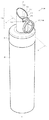
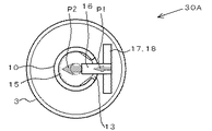
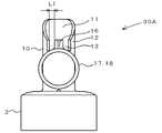
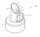
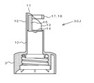
図1Aは、本発明の一実施例の開封構造30Aをキャップ部3に有する詰替容器1の斜視図であり、図1Bはそのキャップ部3のX−X断面図、図1Cはキャップ部3の上面図、図1Dはキャップ部3の正面図である。
FIG. 1A is a perspective view of a
この詰替容器1は、詰替容器本体2が有底筒状であり、詰替容器本体2の上部の口部に螺合するキャップ部3を有し、キャップ部3の天面には、先端が閉じられている注出ノズル10が突出している。なお、詰替容器本体2は、ブロー成型ボトルからなり、注出ノズル10は、キャップ部3と一体に樹脂成型されている。
The
注出ノズル10は、その注出口側端部に、注出ノズル10の中心軸Loに対して開口面が傾いている斜め注出口11を形成する開口部壁12を有している。斜め注出口11の開口面の傾きは、注出液の脈打ちを抑制する点、及び後述する引っ張り部17を斜め注出口11に沿って該斜め注出口11を縦断するように斜め上方向に引っ張るのを容易にする点から、図1Bに示すように、斜め注出口11の開口面の中央部が注出ノズル10の中心軸Loとなす角度θを30〜60°にすることが好ましい。
The pouring
また、斜め注出口11を形成する開口部壁12には、該開口部壁12が除去部14の形成面まで井戸型に部分的に欠如した切欠13が形成されている。
The opening
除去部14は、斜め注出口11の開口面よりも注出ノズル10の基部側で注出ノズル10を閉じている。この場合、除去部14は注出ノズル10の中心軸Loに対して略垂直な板面となっている。このように、注出口は注出ノズル10の中心軸Loに対して傾いている斜め注出口11とするが、除去部14は同じ中心軸Loに対して略垂直な板面で形成することにより、注出ノズル10の成型が容易となり成型精度を向上させることができる。
The removing
除去部14は、易切断部15で囲まれている。易切断部15は、図1Bに示すように、内側から設けられた溝により壁厚が薄くなった薄肉部から形成されている。なお、易切断部15は、このような薄肉部の他、易切断部15の壁厚を表裏から薄くした肉薄部で形成してもよく、ハーフカット等で形成してもよい。また、易切断部15を形成する肉薄部は、連続的又は間欠的に形成することができる。
The
斜め注出口11の下端側の除去部14において、前述の切欠13に隣接する部分には短尺帯状の連結部16が起立している。連結部16は屈曲して切欠13を通り、その端部に引っ張り部17が延設されている。ここで、切欠13により形成される、連結部16と開口部壁12との間隙の幅L1(図1D)は、引っ張り部17の引っ張り方向が斜め注出口11を縦断する方向からぶれにくくするため、狭く形成することが好ましく、例えば、0.5mm〜5mmとする。
In the
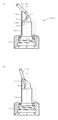
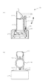
連結部16の長さと、除去部14からの開口部壁12の高さは、斜め注出口11が引っ張り部17の引き上げ時のガイドとなるように調整されている。より具体的には、図2(b)に示すように、除去部14の切断開始時に引っ張り部17の連結部側端部17aが斜め注出口11の切欠13側縁部近傍にくるようにすることが好ましい。また、図2(d)に示すように、除去部14が注出ノズル10から除去される直前の状態で、引っ張り部17の連結部側端部17aが斜め注出口11の先端部近傍にくるようにすること、即ち、除去部14が注出ノズル10から除去される直前の状態で、除去部14と連結部16の合計の高さL4が、除去部14からの開口部壁12の高さL3と同程度になることが好ましい。このため、連結部16の引っ張り部側端部16cと除去部14の斜め注出口先端部側端部との合計の上面視における長さL2と、除去部14からの開口部壁12の高さL3とを、L3/L2=0.5〜2とすることが好ましく、0.8〜1とすることがより好ましい(図2(a)参照)。
The length of the connecting
さらに、引っ張り部17を斜め注出口11に沿って該斜め注出口11を縦断するように引き上げることにより、引っ張り部17の連結部側端部17aが、斜め注出口11の切欠13側縁部近傍(図2(b))から、斜め注出口11の先端部近傍(図2(d))へ移動する間に、引っ張り部17の連結部側端部17aが常に開口部壁12の縁部に沿って移動するように、開口部壁12の高さを、切欠13側から斜め注出口11の先端部側に向けて高くし、斜め注出口11の開口面の中央部が注出ノズル10の中心軸Loとなす角度θを30〜60°にすることが好ましい(図1B)。
Further, by pulling up the pulling
連結部16は除去部14とその外側の易切断部15に跨って起立することなく、除去部14のみから起立している。また、切欠13が幅狭に形成されていることにより、連結部16の除去部側端部は略3方が開口部壁12で囲まれて開口部壁12の内側にあり、連結部16は注出ノズル10の内側から外側へ跨るように配置されている。
The connecting
連結部16の除去部側端部における注出ノズル半径方向の厚さD1は、連結部16の引っ張り部側端部における注出ノズルの半径方向の厚さD2以上とすることが好ましく、連結部16の除去部側端部における厚さD1を引っ張り部側端部における厚さD2よりも大きくすることがより好ましい(図1B)。これにより、後述するように引っ張り部17を引っ張ると、連結部16の除去部中央部側端部16aが除去部14を押し込み、その押し込み部と反対側の易切断部側端部16bがテコの原理で持ち上がり、その近傍の易切断部15に剪断応力が集中するので、容易に易切断部15に破断を起こさせることができる(図2(b))。なお、連結部16の除去部側端部における厚さD1と、引っ張り部側端部における厚さD2とは、開封作業中に変化するが、ここでいう厚さは、外部応力がかかっていない時の厚さをいう。
The thickness D1 in the radial direction of the discharging nozzle at the removal portion side end of the connecting
除去部14と連結部16の外表面には、注出ノズル10の開封時に引っ張り部17を引っ張る方向を示す図柄として矢印表示P1、P2が設けられている。
Arrow indications P1 and P2 are provided on the outer surfaces of the removing
本実施例において、引っ張り部17は、その全体が注出ノズル10の開口部壁12の外側に位置し、リング状の指掛けリング18に成形されている。指掛けリング18は引っ張りやすいように、その外径が注出ノズル10の内径よりも大きく、リング内に指を通して指掛けリング18に指を掛けることを可能としている。
In the present embodiment, the
また、引っ張り部17は、注出ノズル10の側面に沿って垂下している。引っ張り部17が斜め注出口11の上に突出していると、詰替容器1が注出ノズル10側から床に落下した場合に、引っ張り部17が床面に衝突することにより易切断部15が不用に破断することが懸念されるが、引っ張り部17が注出ノズル10の側面に沿って垂下していることにより、このような易切断部15の不用な破断を防止することができる。
In addition, the pulling
引っ張り部17の先端部は、注出ノズル10が起立する基面となっているキャップ部3の天面と、手で容易に切り離すことのできるように接続している。これにより、詰替容器1の搬送途中に、指掛けリング18が曲がるなどして周囲に引っかかり、誤って開封されることを防止できる。なお、このように引っ張り部17を注出ノズル10に沿ってつなぎ止める方法としては、引っ張り部17の先端部を注出ノズル10の側面と切り離し可能に接続してもよい。
The tip of the pulling
この開封構造30Aは、次のような開封操作により、閉じられている注出ノズル10を開封する。まず、図2(a)に示すように、開封構造30Aの指掛けリング18に成形された引っ張り部17をキャップ部3の天面から切り離し、指掛けリング18に指をかけ、矢印表示P1にしたがって指掛けリング18を引き上げ、指掛けリング18の上下の面を反転させてさらに引き上げる(図2(b))。これにより、連結部16の除去部中央部側端部16aで除去部14が斜め下に押し込まれ、それと対向する連結部16の易切断部側端部16bには、テコの原理によりそこを持ち上げるモーメントが働き、その部分の易切断部15aが容易に破断して開封開始部となる。引き続き、矢印表示P2にしたがって引っ張り部17を、斜め注出口11を縦断するように斜め上方に引き上げると易切断部15の破断が広がる。ここで、開封者は引っ張り部17を、斜め注出口11に沿って斜め上方(矢印a方向)に引き上げることはできるが(図2(c)、図4(a)、図5(a))、それ以外の方向には引っ張り部17と開口部壁12の切欠側端部12aとが干渉するので引き上げにくくなっている。特に、本実施例では、連結部16の除去部側端部16aが開口部壁12で囲まれ、連結部16が注出ノズル10の内側から外側に跨るように配置され、さらに引っ張り部17の連結部側端部17aが、除去部14の切断開始時には斜め注出口11の切欠13側縁部近傍に位置し、除去部14が注出ノズル10から除去される直前では、斜め注出口11の先端部近傍に位置し、除去部14の切断開始から除去直前までの間では、引っ張り部17の連結部側端部17aが、開口部壁12の縁部に沿って移動するように開口部壁12が調整されていることにより、易切断部15aの開封開始時(図2(b))においても、それに続く易切断部15aの破断時(図2(c))においても、引っ張り部17の引っ張り方向が斜め注出口11を縦断する方向からぶれにくく、安定化する。したがって、連結部16が捻れて引き上げられた場合に生じる、引っ張り部17と連結部16との断裂や、連結部16と除去部14との断裂を防止することができる。
This unsealing
これに対し、引っ張り部17の引き上げ時に、引っ張り部17を沿わせる斜め注出口11が無い場合には、図4(b)に矢印a、b1、b2で示すように種々の方向に引っ張り部17を引っ張ることができるため、引っ張り方向が一定方向に定まらない。したがって、引っ張り部17の引き上げ時に連結部16が捻れて、引っ張り部17と連結部16とが断裂したり、連結部16と除去部14とが断裂したりすることを無くすことが困難となる。また、図5(b)に示すように、斜め注出口を形成する開口部壁12は形成されていても、切欠13が幅広く形成されていることにより連結部16の除去部側端部が注出ノズル10の外側にある場合にも、矢印a、b1、b2で示すように種々の方向に引っ張り部17を引っ張ることができるため、引っ張り方向が一定方向に定まらない。
On the other hand, when the pulling
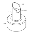
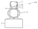
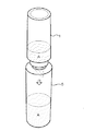
こうして、引っ張り部17を引き上げて除去部14を取り除くことにより、注出ノズル10を開封することができる(図2(d))。図3は、除去部14の除去により開封した注出ノズル10の斜視図である。
Thus, by pulling up the pulling
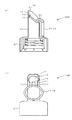
注出ノズル10を開封した詰替容器1は、図17Aに示すように、本容器5への内容液Aの詰替に供することができる。この詰替操作では、図17Bに示すように、本容器5の口部に詰替容器1の斜め注出口11を挿入し、詰替容器1を倒立させ、詰替容器1と本容器5を自立させた状態にする。詰替容器1や本容器5が自立可能な柱状容器であると、このような詰替操作の間に、詰替容器1や本容器5を格別把持する必要が無く、詰替作業の手間を大いに軽減することができる。さらに、詰替容器1の注出口が斜め注出口11であるため、注出時に空気置換が円滑に行われる。このため、注出時に内容液Aの脈打ちを抑え、詰替容器1から本容器5へ滑らかに内容液Aを詰め替えることができる。したがって、内容液Aがこぼれたり、本容器5内で不用に泡だったりすることを抑制できる。この内容液Aの脈打ち抑制効果は、例えば、内容液Aの粘度が500mPas〜10000mPasの場合に、注出ノズル10の内径を12〜20mmとし、斜め注出口11の斜めの角度θを40〜50°とする場合に顕著となる。
The
本発明の開封構造は種々の態様をとることができる。例えば、図6に示す開封構造30Bは、図1Aの開封構造30Aの井戸型の切欠13に代えて、開口部壁12の欠如部分から滑らかに開口部壁12を立ち上げたものである。引っ張り部17の引っ張り方向を安定化させる点では、開封構造30Aの切欠13が好ましい。
The unsealing structure of the present invention can take various forms. For example, the
図7の開封構造30Cは、図1Aの開封構造30Aに対して井戸型の切欠13を無くし、除去部14の全周が開口部壁12で囲まれるようにしたものである。このように除去部14の全周が開口部壁12で囲まれるようにしても、連結部16近傍の開口部壁12の高さを低くすることにより、引っ張り部17を斜め注出口11に沿わせて引っ張ることができるので、引っ張り方向を安定化させることが可能となる。
The opening
図8(a)の開封構造30Dは、図1Aの開封構造30Aに対し、除去部14の厚さに関し、連結部16の基部から開封方向に位置する領域21の厚さD3を、除去部14の他の領域の厚さD4よりも厚くしたものであり、図8(b)は、この開封構造30Dの上面図である。このように肉厚の領域21を設けることにより、引っ張り部17を引き上げて開封する際に、図9(a)に示すように、除去部14が撓むことを抑制することができる。これに対し、除去部14が撓みやすいと、図9(b)に示すように、引っ張り部17の引き上げ時に除去部14が折れ曲がりやすくなる。そして、図9(a)に示すように除去部14を撓みにくくすると、引っ張り部17の引き上げにより、引っ張り方向にある易切断部15bを支点として除去部14を引き上げ易くなり、より確実に易切断部15を破断させて除去部14を取り除くことが可能となる。
The
本発明の開封構造においては、引っ張り部17を可撓性樹脂から形成し、引っ張り部17を形成する指掛けリング18に種々の形状をとらせることができる。
例えば、図10Aの開封構造30Eは、指掛けリング18を可撓性樹脂により楕円形のリングに形成したものである。指掛けリング18が円形のリングであり、それがリジッドな樹脂で形成されていると、注出ノズル10が短尺である場合には、キャップ部3の天面から連結部16までの高さが十分にとれないことにより、指掛けリング18を形成する円形のリングの直径も小さくなり、指を掛けにくくなる。これに対し、図10Aの開封構造30Eのように可撓性樹脂を用いて指掛けリング18を楕円形のリングとすると、その長径を、指を掛けやすいリング径に調整することができる。したがって、指掛けリング18における指の掛けやすさを確保することができる。
In the opening structure of the present invention, the pulling
For example, the opening structure 30E of FIG. 10A is obtained by forming the
指掛けリング18を可撓性樹脂から形成するに際し、そのリング形状には特に制限はなく、例えば、図10Bの開封構造30Fに示すように、蒲鉾型としてもよく、図10Cの開封構造30Gに示すように、矩形としてもよい。
When the
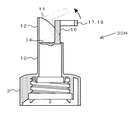
図11の開封構造30Hは、図1Aの開封構造30Aに対し、引っ張り部17を形成する指掛けリング18を、注出ノズル10の側面に沿って垂下させずに、開口部壁12の外側であって、除去部14の斜め上方で、指掛けリング18のリング面が除去部14に略平行になるように設けたものである。この開封構造30Hにおいても、引っ張り部17が開口部壁12の外側に設けられており、引っ張り部17を斜め注出口11に沿わせて引っ張れるように連結部16の長さと、除去部14からの開口部壁12の高さが調整されている。したがって、引っ張り部17の引っ張り方向を安定化させることができる。
The
図12の開封構造30Iは、図11の開封構造30Hに対し、除去部14における連結部16の起立位置を、斜め注出口11の上端側に変更したものである。この開封構造30Iでは引っ張り部17の略半分が、開口部壁12の外側に位置している。このように本発明において、引っ張り部が開口部壁外側に延設されているとは、引っ張り部17の全体が開口部壁12の外側に設けられている場合に限らない。引っ張り部17を引っ張ることができる限り、引っ張り部17の一部が開口部壁12の内部に位置していてもよい。
The opening structure 30I in FIG. 12 is obtained by changing the standing position of the connecting
また、この開封構造30Iでは、注出ノズル10の開封時に引っ張り部17が矢印の方向に引き下げられるが、連結部16の長さと、除去部14からの開口部壁12の高さは、引っ張り部17の引き下げ時に斜め注出口11に沿わせられるように調整されている。したがって、この開封構造30Iにおいても、引っ張り部17の引っ張り方向を安定化させることができる。
In the opening structure 30I, the pulling
図13の開封構造30Jは、図12の開封構造30Iにおいて注出ノズル10の上端部をスパウト状に突出させたものである。スパウト状に突出させても、脈動することなく安定して詰め替えることができる。
The
図14の開封構造30Kは、図12の開封構造30Iにおいて連結部16を長くすることにより、引っ張り部17の全体を開口部壁12の外側に設けたものである。これにより、引っ張り部17に指を掛けやすくなる。
The opening
図15の開封構造30Lは、図1Aの開封構造30Aにおいて、引っ張り部17の先端部とキャップ部3の天面との切り離し可能な接合に代えて、引っ張り部17の先端部に球状の嵌合用凸部材19を設け、キャップ部3の天面に、その嵌合用凸部材19に嵌合する嵌合用凹部材20を設け、引っ張り部17とキャップ部3とを着脱自在としたものである。
The
図16の開封構造30Mは、図1Aの開封構造30Aにおいて、除去部14を斜め注出口11の開口面と略平行に形成したものである。このように、除去部14を構成する板面の角度は、注出ノズル10の中心軸L0に対して略垂直から斜め注出口11の開口面に対して略平行までの角度をとることができる。
An
本発明は、さらに種々の態様をとることができる。例えば、本発明の開封構造において、引っ張り部17はリング状の指掛け部に限らず、板状であってもよい。
The present invention can take various modes. For example, in the opening structure of the present invention, the pulling
また、本発明の開封構造は、キャップ部から突出した注出ノズルに形成されることに限られない。例えば、詰替容器本体の天面から直接突出した注出ノズルに形成してもよい。この場合、詰替容器本体の底部に開口部を設けておき、その底部の開口部から詰替容器本体へ内容液を充填し、充填後に底部の開口部をヒートシール等により封じきればよい。 Moreover, the opening structure of this invention is not restricted to being formed in the extraction nozzle protruded from the cap part. For example, you may form in the extraction nozzle which protruded directly from the top | upper surface of the refill container main body. In this case, an opening is provided at the bottom of the refill container body, the content liquid is filled into the refill container body from the opening at the bottom, and the bottom opening is sealed by heat sealing or the like after filling.
また、上述した各開封構造には、それを着脱自在に覆う保護カバーを被せてもよい。さらに、上述した各開封構造の構成要素は適宜組み合わせることができる。 Further, each opening structure described above may be covered with a protective cover that detachably covers it. Furthermore, the constituent elements of the respective opening structures described above can be appropriately combined.
1 詰替容器
2 詰替容器本体
3 キャップ部
5 本容器
10 注出ノズル
11 斜め注出口
12 開口部壁
12a 開口部壁の切欠側端部
13 切欠
14 除去部
15、15a、15b 易切断部
16 連結部
16a 連結部の除去部中央部側端部
16b 連結部の易切断部側端部
16c 連結部の引っ張り部側端部
17 引っ張り部
17a 引っ張り部の連結部側端部
18 指掛けリング
19 嵌合用凸部材
20 嵌合用凹部材
21 肉厚の領域
30A、30B、30C、30D、30E、30F、30G、30H,30I、30J、30K、30L、30M 開封構造
A 内容液
Lo 注出ノズルの中心軸
L1 連結部と開口部壁との間隙の幅
L2 連結部の引っ張り部側端部と除去部の斜め注出口先端部側端部との合計の長さ
L3 除去部からの開口部壁の高さ
L4 除去部と連結部の合計の高さ
P1、P2 矢印表示
θ 斜め注出口の開口面の中央部が注出ノズルの中心軸となす角度
DESCRIPTION OF
Claims (9)
Priority Applications (1)
| Application Number | Priority Date | Filing Date | Title |
|---|---|---|---|
| JP2011128154A JP5733037B2 (en) | 2011-06-08 | 2011-06-08 | Opening structure |
Applications Claiming Priority (1)
| Application Number | Priority Date | Filing Date | Title |
|---|---|---|---|
| JP2011128154A JP5733037B2 (en) | 2011-06-08 | 2011-06-08 | Opening structure |
Publications (2)
| Publication Number | Publication Date |
|---|---|
| JP2012254803A true JP2012254803A (en) | 2012-12-27 |
| JP5733037B2 JP5733037B2 (en) | 2015-06-10 |
Family
ID=47526783
Family Applications (1)
| Application Number | Title | Priority Date | Filing Date |
|---|---|---|---|
| JP2011128154A Active JP5733037B2 (en) | 2011-06-08 | 2011-06-08 | Opening structure |
Country Status (1)
| Country | Link |
|---|---|
| JP (1) | JP5733037B2 (en) |
Cited By (4)
| Publication number | Priority date | Publication date | Assignee | Title |
|---|---|---|---|---|
| JP2014148328A (en) * | 2013-01-31 | 2014-08-21 | Yoshino Kogyosho Co Ltd | Refill container |
| JP2015048118A (en) * | 2013-08-30 | 2015-03-16 | 株式会社吉野工業所 | Refill container |
| JP2018111500A (en) * | 2017-01-06 | 2018-07-19 | 凸版印刷株式会社 | Refill container |
| CN113993792A (en) * | 2019-06-28 | 2022-01-28 | 莱雅公司 | Dispensing assembly for flexible packages |
Citations (7)
| Publication number | Priority date | Publication date | Assignee | Title |
|---|---|---|---|---|
| JPS5348207Y2 (en) * | 1972-12-26 | 1978-11-17 | ||
| JPS5815315Y2 (en) * | 1978-11-16 | 1983-03-28 | 三笠産業株式会社 | Container lid with cutout |
| JP2558394Y2 (en) * | 1992-11-18 | 1997-12-24 | 凸版印刷株式会社 | Spout for liquid paper container |
| JP2007223658A (en) * | 2006-02-27 | 2007-09-06 | Pentel Corp | Sealed container |
| JP2007331769A (en) * | 2006-06-12 | 2007-12-27 | Japan Crown Cork Co Ltd | Pouring implement |
| JP4426224B2 (en) * | 2003-07-17 | 2010-03-03 | 日本テトラパック株式会社 | Packaging container |
| JP2011046445A (en) * | 2009-07-29 | 2011-03-10 | Yoshino Kogyosho Co Ltd | Spouting container |
-
2011
- 2011-06-08 JP JP2011128154A patent/JP5733037B2/en active Active
Patent Citations (7)
| Publication number | Priority date | Publication date | Assignee | Title |
|---|---|---|---|---|
| JPS5348207Y2 (en) * | 1972-12-26 | 1978-11-17 | ||
| JPS5815315Y2 (en) * | 1978-11-16 | 1983-03-28 | 三笠産業株式会社 | Container lid with cutout |
| JP2558394Y2 (en) * | 1992-11-18 | 1997-12-24 | 凸版印刷株式会社 | Spout for liquid paper container |
| JP4426224B2 (en) * | 2003-07-17 | 2010-03-03 | 日本テトラパック株式会社 | Packaging container |
| JP2007223658A (en) * | 2006-02-27 | 2007-09-06 | Pentel Corp | Sealed container |
| JP2007331769A (en) * | 2006-06-12 | 2007-12-27 | Japan Crown Cork Co Ltd | Pouring implement |
| JP2011046445A (en) * | 2009-07-29 | 2011-03-10 | Yoshino Kogyosho Co Ltd | Spouting container |
Cited By (5)
| Publication number | Priority date | Publication date | Assignee | Title |
|---|---|---|---|---|
| JP2014148328A (en) * | 2013-01-31 | 2014-08-21 | Yoshino Kogyosho Co Ltd | Refill container |
| JP2015048118A (en) * | 2013-08-30 | 2015-03-16 | 株式会社吉野工業所 | Refill container |
| JP2018111500A (en) * | 2017-01-06 | 2018-07-19 | 凸版印刷株式会社 | Refill container |
| CN113993792A (en) * | 2019-06-28 | 2022-01-28 | 莱雅公司 | Dispensing assembly for flexible packages |
| CN113993792B (en) * | 2019-06-28 | 2023-09-19 | 莱雅公司 | Dispensing assembly for flexible packages |
Also Published As
| Publication number | Publication date |
|---|---|
| JP5733037B2 (en) | 2015-06-10 |
Similar Documents
| Publication | Publication Date | Title |
|---|---|---|
| JP5516275B2 (en) | Opening structure of oblique outlet | |
| JP5733037B2 (en) | Opening structure | |
| JP5669486B2 (en) | Liquid dispensing container | |
| JP2006306459A (en) | Cap with inner stopper | |
| JP2016520024A (en) | Improved container with opening | |
| TWI505970B (en) | Refill method | |
| JP5790114B2 (en) | Repeated use container | |
| JP2011046445A (en) | Spouting container | |
| JP5415021B2 (en) | Hinge cap | |
| JP6086743B2 (en) | Refill container | |
| JP5644139B2 (en) | Refill method | |
| JP2011011765A (en) | Combination of continuously using container and refilling container | |
| JP5444937B2 (en) | Repeated use container | |
| JP2015051809A (en) | Refilling method | |
| JP2012012070A (en) | Spout cap for container | |
| JP5611543B2 (en) | Liquid pool prevention cap | |
| JP2018154395A (en) | Pouring port opening structure | |
| JP2007055659A (en) | Dispenser container | |
| JP2001097432A (en) | Pouring-out cap | |
| JP4966734B2 (en) | Lid with extraction tube | |
| JP2013079084A (en) | Refill container | |
| JP2011079566A (en) | Pouring tool equipped with opening tool | |
| JP5818735B2 (en) | Cap with pull ring | |
| JP5370988B2 (en) | Dispensing container | |
| JP2006298498A (en) | Liquid pouring-out container |
Legal Events
| Date | Code | Title | Description |
|---|---|---|---|
| A621 | Written request for application examination |
Free format text: JAPANESE INTERMEDIATE CODE: A621 Effective date: 20140306 |
|
| A977 | Report on retrieval |
Free format text: JAPANESE INTERMEDIATE CODE: A971007 Effective date: 20141119 |
|
| A131 | Notification of reasons for refusal |
Free format text: JAPANESE INTERMEDIATE CODE: A131 Effective date: 20141125 |
|
| A521 | Request for written amendment filed |
Free format text: JAPANESE INTERMEDIATE CODE: A523 Effective date: 20150126 |
|
| TRDD | Decision of grant or rejection written | ||
| A01 | Written decision to grant a patent or to grant a registration (utility model) |
Free format text: JAPANESE INTERMEDIATE CODE: A01 Effective date: 20150317 |
|
| A61 | First payment of annual fees (during grant procedure) |
Free format text: JAPANESE INTERMEDIATE CODE: A61 Effective date: 20150330 |
|
| R151 | Written notification of patent or utility model registration |
Ref document number: 5733037 Country of ref document: JP Free format text: JAPANESE INTERMEDIATE CODE: R151 |
|
| R250 | Receipt of annual fees |
Free format text: JAPANESE INTERMEDIATE CODE: R250 |
|
| R250 | Receipt of annual fees |
Free format text: JAPANESE INTERMEDIATE CODE: R250 |
|
| R250 | Receipt of annual fees |
Free format text: JAPANESE INTERMEDIATE CODE: R250 |
|
| R250 | Receipt of annual fees |
Free format text: JAPANESE INTERMEDIATE CODE: R250 |
|
| R250 | Receipt of annual fees |
Free format text: JAPANESE INTERMEDIATE CODE: R250 |
|
| R250 | Receipt of annual fees |
Free format text: JAPANESE INTERMEDIATE CODE: R250 |
|
| R250 | Receipt of annual fees |
Free format text: JAPANESE INTERMEDIATE CODE: R250 |