JP2012253452A - 3d image imaging apparatus and program - Google Patents
3d image imaging apparatus and program Download PDFInfo
- Publication number
- JP2012253452A JP2012253452A JP2011122667A JP2011122667A JP2012253452A JP 2012253452 A JP2012253452 A JP 2012253452A JP 2011122667 A JP2011122667 A JP 2011122667A JP 2011122667 A JP2011122667 A JP 2011122667A JP 2012253452 A JP2012253452 A JP 2012253452A
- Authority
- JP
- Japan
- Prior art keywords
- image data
- parallax
- output image
- eye
- imaging
- Prior art date
- Legal status (The legal status is an assumption and is not a legal conclusion. Google has not performed a legal analysis and makes no representation as to the accuracy of the status listed.)
- Withdrawn
Links
Images


Abstract
Description
本発明は3D画像撮像装置及びプログラムに関し、より詳細には光学ズーム倍率が変更されても出力される被写体画像の立体感及び出力される画像のアスペクト比を維持することができる3D画像撮像装置及びプログラムに関する。 The present invention relates to a 3D image capturing apparatus and program, and more specifically, a 3D image capturing apparatus capable of maintaining the stereoscopic effect of an output subject image and the aspect ratio of the output image even when the optical zoom magnification is changed, and Regarding the program.
近年、水平方向に視差を有する2つの画像が左眼用画像及び右眼用画像として同一の表示面上に表示され、観察者が左眼用画像を左眼で、右眼用画像を右眼でそれぞれ独立して観察することで、表示面上に表示された被写体画像があたかも立体的に存在するかのように知覚できる3D画像に関する技術の開発が盛んに行われている。 In recent years, two images having a parallax in the horizontal direction are displayed on the same display surface as a left-eye image and a right-eye image, and an observer uses the left-eye image as the left eye and the right-eye image as the right eye. Thus, by independently observing each of the images, a technique relating to a 3D image that can be perceived as if the subject image displayed on the display surface exists three-dimensionally has been actively developed.
3D画像の表示及び観察方式としては、互いに直交する直線偏光を有する左眼用画像及び右眼用画像が表示面上に重ねて表示され、観察者が偏光フィルタの付いた眼鏡を用いて左眼で左眼用画像を、右眼で右眼用画像をそれぞれ独立して観察する方式がよく知られている。 As a 3D image display and observation method, a left-eye image and a right-eye image having linearly polarized light that are orthogonal to each other are displayed superimposed on the display surface, and an observer uses glasses with a polarization filter to display the left eye. The method of independently observing the image for the left eye and the image for the right eye with the right eye is well known.
また、左眼用画像及び右眼用画像それぞれが交互に表示面上に表示され、観察者が左眼及び右眼の視界が交互に遮蔽される液晶シャッタの付いた眼鏡を用いて左眼で左眼用画像を、右眼で右眼用画像をそれぞれ独立して観察する方式もよく知られている。 Also, the left-eye image and the right-eye image are alternately displayed on the display surface, and the observer uses the glasses with a liquid crystal shutter with the left-eye and right-eye fields alternately shielded with the left eye. A method of independently observing the image for the left eye and the image for the right eye with the right eye is also well known.
これらの3D画像に関する技術では、観察者から見て3D画像中の被写体画像が、表示面に対しどの程度前方に飛び出しているように知覚されるか、又は表示面に対しどの程度後方に引っ込んでいるように知覚されるかは、左眼用画像における被写体画像と、それに対応する右眼用画像における被写体画像との間の水平方向の視差によって決定される。 In these 3D image technologies, it is perceived as if the subject image in the 3D image is projected forward from the display surface as viewed from the observer, or how far the object image is retracted from the display surface. Is determined by the parallax in the horizontal direction between the subject image in the left-eye image and the corresponding subject image in the right-eye image.
そこで、左眼用画像と右眼用画像との間の水平方向の視差を調整しつつ3D画像を撮像する撮像装置に関する技術の開発が盛んに行われている。例えば、特許文献1には、左眼画像と右眼画像のそれぞれから顔が検出された特定対象の代表座標及びそれら代表座標間の差分ベクトルを算出し、その差分ベクトルに基づいて左眼画像中における特定対象の表示位置及び右眼画像中における特定対象の表示位置を調整して視差量の調整を行うことで、ユーザの位置合わせ操作を必要とせず、且つ少ない演算量で画像の位置合わせを行うことができる立体画像処理装置が記載されている。
In view of this, technology relating to an imaging apparatus that captures a 3D image while adjusting the parallax in the horizontal direction between the image for the left eye and the image for the right eye has been actively developed. For example, in
また、特許文献2には、複数のレンズを通して得られた複数の画像データに関し、それら複数の画像データのそれぞれから互いの重複範囲の画像データを切り出す画枠を設定する際に、被写体までの距離が所定距離以上のときは所定アスペクト比の横長画枠とし、被写体までの距離が所定距離未満のときは所定アスペクト比の縦長画枠とすることで、近い所の被写体であっても水平方向に視差を有する複数の画像を取得し、立体映像を撮影できる立体撮影装置が記載されている。
Further, in
上記特許文献1に記載の立体画像処理装置では、メモリ(SDRAM)からの左眼画像データ及び右眼画像データの読み出し範囲を調整することで、左眼画像と右眼画像との間の視差の調整を行っている。しかし、左眼画像データ及び右眼画像データの水平方向の読み出し範囲を変更した場合は、左右の撮像部のレンズの光軸と、メモリから読み出される左右の画像に対し擬似的に認識される光軸とが不一致となる。
In the stereoscopic image processing apparatus described in
従って、ユーザが撮像中に、視差の調整を行った後、ズームレンズ等を駆動して、視差の調整を行った際の光学ズーム倍率から別の光学ズーム倍率に設定を変更した場合、撮像系のレンズの光軸の位置は変化しないのに、メモリから読み出される左右の画像に対し擬似的に認識される光軸の位置は変化してしまう。 Accordingly, when the user adjusts the parallax during imaging and then drives the zoom lens or the like to change the setting from the optical zoom magnification at the time of parallax adjustment to another optical zoom magnification, the imaging system Although the position of the optical axis of this lens does not change, the position of the optical axis that is artificially recognized for the left and right images read from the memory changes.
これにより、メモリから読み出される左右の画像対し擬似的に認識される光軸の交わる点、すなわち左右の画像間の視差がゼロとなる輻輳点の位置が、光学ズーム倍率の変更前と変更後とで変化してしまい、出力される被写体画像の立体感が光学ズーム倍率変更前に意図したものとは異なるものへと変化してしまうという問題の発生が推察される。 As a result, the point at which the optical axes that are pseudo-recognized with respect to the left and right images read out from the memory, that is, the position of the convergence point where the parallax between the left and right images is zero, are the before and after the change of the optical zoom magnification It is assumed that there is a problem that the stereoscopic effect of the output subject image changes to a different one from that intended before the change of the optical zoom magnification.
さらに、上記特許文献1に記載の立体画像処理装置では、メモリに記録された左眼画像データ及び右眼画像データの水平方向に余裕がない場合は、調整のための水平方向の画像データが不足する場合があることが推測される。この場合、出力される3D画像のアスペクト比は、不足しない場合とは異なったものに変化してしまうという問題の発生も推察される。
Furthermore, in the stereoscopic image processing apparatus described in
また、上記特許文献2に記載の立体撮影装置では、近い所の被写体であっても立体映像として撮影ができるものの、上記特許文献1に記載の立体画像処理装置と同様に、ズームレンズ等を駆動して光学ズーム倍率を変更した場合には、撮像系のレンズの光軸の位置は変化しないのに、メモリから読み出される左右の画像に対し擬似的に認識される光軸の位置は変化してしまう。従って、撮影された被写体画像の立体感は、光学ズーム倍率毎に異なったものとなってしまうという問題の発生が推察される。
Further, although the stereoscopic imaging device described in
さらに、出力画像のアスペクト比が調整されているとはいえ、被写体までの所定距離を境に、横長画枠と縦長画枠とが切り換えられるため、画像の横と縦の長さの比率は、例えは4:3から3:4という様に、変更されてしまう。従って、出力画像の画素数及び大きさは維持されても、縦辺と横辺の比率そのものは維持されないという問題がある。 Furthermore, even though the aspect ratio of the output image has been adjusted, the horizontal and vertical image frames are switched at the predetermined distance to the subject, so the ratio of the horizontal and vertical length of the image is The example is changed from 4: 3 to 3: 4. Therefore, there is a problem that even if the number of pixels and the size of the output image are maintained, the ratio of the vertical side to the horizontal side is not maintained.
本発明はこの問題に鑑みてなされたものであり、左眼用画像と右眼用画像との間の視差が調整された後、光学ズーム倍率が変更された場合であっても、光学ズーム倍率が変更される前の出力される被写体画像の立体感及び出力される画像のアスペクト比を維持することができる3D画像撮像装置及びプログラムを提供することを目的とする。 The present invention has been made in view of this problem, and even when the optical zoom magnification is changed after the parallax between the left-eye image and the right-eye image is adjusted, the optical zoom magnification is changed. An object of the present invention is to provide a 3D image capturing apparatus and program capable of maintaining the stereoscopic effect of the output subject image before the change of the image and the aspect ratio of the output image.
前記目的を達成するために、本発明は、第一変倍レンズ(L111)と、その第一変倍レンズ(L111)を光軸に沿って駆動させる第一駆動部(L116)とを有し、第一撮像データを取得する第一撮像部(L110)と、第二変倍レンズ(R111)と、その第二変倍レンズ(R111)を光軸に沿って駆動させる第二駆動部(R115)とを有し、第二撮影画像データを取得する第二撮像部(R110)と、前記第一撮像データと前記第二撮像データとの間の視差を算出する視差算出部(102)と、前記視差算出部(102)が算出した前記視差に基づき、前記第一撮像データから抽出する第一出力画像データの水平方向の位置、及び前記第二撮像データから抽出する第二出力画像データの水平方向の位置を調整することで、第一出力画像データと第二出力画像データとの間の水平方向の視差を調整する視差調整部(102)と、前記第一出力画像データ及び前記第二出力画像データの所定のアスペクト比を維持するアスペクト比維持部(106)とを備え、前記視差調整部(103)による前記水平方向の視差の調整が行われた後に、前記第一駆動部(L115)により前記第一変倍レンズ(L111)の倍率が変更され、かつ前記第二駆動部(R115)により前記第二変倍レンズ(R111)の倍率が変更された場合に、前記視差調整部(103)は前記水平方向の視差の調整によって水平方向の視差がゼロとなっている被写体画像が前記倍率の変更後も水平方向の視差がゼロとなるように前記第一出力画像データの水平方向の位置、及び前記第二出力画像データの水平方向の位置を再度調整し、前記アスペクト比維持部(106)は前記第一出力画像データ及び前記第二出力画像データの領域サイズを変更することで、前記倍率の変更後もアスペクト比を維持することを特徴とする3D画像撮像装置(1)を提供する。 In order to achieve the above object, the present invention includes a first variable magnification lens (L111) and a first drive unit (L116) that drives the first variable magnification lens (L111) along the optical axis. The first imaging unit (L110) that acquires the first imaging data, the second variable magnification lens (R111), and the second drive unit (R115) that drives the second variable magnification lens (R111) along the optical axis. ), A second imaging unit (R110) that acquires second captured image data, a parallax calculation unit (102) that calculates parallax between the first imaging data and the second imaging data, Based on the parallax calculated by the parallax calculation unit (102), the horizontal position of the first output image data extracted from the first imaging data and the horizontal of the second output image data extracted from the second imaging data. By adjusting the direction position, A parallax adjustment unit (102) that adjusts the parallax in the horizontal direction between the image data and the second output image data, and an aspect ratio that maintains a predetermined aspect ratio of the first output image data and the second output image data And a magnification of the first variable magnification lens (L111) by the first drive unit (L115) after the parallax adjustment in the horizontal direction is performed by the parallax adjustment unit (103). Is changed and the magnification of the second variable magnification lens (R111) is changed by the second driving unit (R115), the parallax adjusting unit (103) adjusts the horizontal parallax by adjusting the horizontal parallax. The position of the first output image data in the horizontal direction and the second output image data so that the subject image for which the parallax is zero remains zero in the horizontal direction even after the magnification is changed. The horizontal position is adjusted again, and the aspect ratio maintaining unit (106) maintains the aspect ratio after changing the magnification by changing the area size of the first output image data and the second output image data. A 3D image pickup device (1) is provided.
本発明に係る3D画像撮像装置(1)によれば、左眼用出力画像データと右眼用出力画像データとの間の水平方向の視差が調整された後に、光学ズーム倍率が変更された場合であっても、その水平方向の視差の調整時に視差がゼロとなっていた被写体画像の視差を引続きゼロに維持するとともに出力画像データのアスペクト比を維持することができるので、出力される被写体画像の立体感及び出力される画像のアスペクト比を維持することができる。 According to the 3D imaging apparatus (1) according to the present invention, when the optical zoom magnification is changed after the horizontal parallax between the left-eye output image data and the right-eye output image data is adjusted. Even so, the parallax of the subject image whose parallax was zero at the time of adjusting the parallax in the horizontal direction can be maintained at zero and the aspect ratio of the output image data can be maintained. 3D effect and the aspect ratio of the output image can be maintained.
上記3D画像撮像装置(1)は、上記第一撮像データ及び上記第二撮像データのそれぞれから人物の顔画像データを検出する顔検出部(205)をさらに備え、上記視差調整部(103)は前記顔検出部(205)が検出した顔画像データに基づき、上記第一撮像データから抽出する第一出力画像データの水平方向の位置、及び上記第二撮像データから抽出する第二出力画像データの水平方向の位置を調整することで、第一出力画像データと第二出力画像データとの間の水平方向の視差を調整するようにしてもよい。 The 3D image capturing apparatus (1) further includes a face detection unit (205) that detects a human face image data from each of the first imaging data and the second imaging data, and the parallax adjustment unit (103) Based on the face image data detected by the face detection unit (205), the horizontal position of the first output image data extracted from the first imaging data and the second output image data extracted from the second imaging data. The horizontal parallax between the first output image data and the second output image data may be adjusted by adjusting the position in the horizontal direction.
これにより、被写体となる人物について、撮像装置1の光学ズーム倍率が変更された後であっても、その人物画像の立体感を維持し、かつ出力される画像のアスペクト比を維持することができる。
Thereby, even after the optical zoom magnification of the
また、上記3D画像撮像装置(1)は、前記第一出力画像データと前記第二出力画像データとの間の水平方向の視差について、ユーザが所望の視差を入力することができる入力手段(306)をさらに備え、前記視差調整部(103)は前記入力された前記視差に基づき、前記第一撮像データから抽出する第一出力画像データの水平方向の位置、及び前記第二撮像データから抽出する第二出力画像データの水平方向の位置を調整することで、第一出力画像データと第二出力画像データとの間の水平方向の視差を調整するようにしてもよい。 In addition, the 3D image capturing apparatus (1) includes an input unit (306) that allows a user to input a desired parallax with respect to a horizontal parallax between the first output image data and the second output image data. ), And the parallax adjustment unit (103) extracts the horizontal position of the first output image data extracted from the first imaging data and the second imaging data based on the input parallax. The horizontal parallax between the first output image data and the second output image data may be adjusted by adjusting the horizontal position of the second output image data.
これにより、ユーザが意図した立体感を有する3D画像を、撮像装置1の光学ズーム倍率が変更された後であっても維持することができ、かつ出力される画像のアスペクト比を維持することができる。
Accordingly, a 3D image having a stereoscopic effect intended by the user can be maintained even after the optical zoom magnification of the
さらに、上述の課題を解決するために、本発明は、第一変倍レンズ(L111)とその第一変倍レンズ(L111)を光軸に沿って駆動させる第一駆動部(L115)とを有する第一撮像部(L110)に第一の撮像データを、第二変倍レンズ(R111)とその第二変倍レンズ(R111)を光軸に沿って駆動させる第二駆動部(R115)とを有する第二撮像部(R110)に第二撮像データをそれぞれ取得させ、前記第一撮像データと前記第二撮像データとの間の視差を算出させ、前記算出させた視差に基づいて、前記第一撮像データから抽出される第一出力画像データの水平方向の位置、及び前記第二撮像データから抽出される第二出力画像データの水平方向の位置を調整させる指示をコンピュータに実行させるプログラムであって、前記第一出力画像データ及び前記第二出力画像データの水平方向の位置を調整した後に、前記第一駆動部(L115)により前記第一変倍レンズ(L111)の倍率が変更され、かつ前記第二駆動部(R115)により前記第二変倍レンズ(R111)の倍率が変更された場合に、その水平方向の位置の調整により水平方向の視差がゼロとなっている被写体画像が前記倍率の変更後も水平方向の視差がゼロとなるように前記第一出力画像データの水平方向の位置、及び前記第二出力画像データの水平方向の位置を再度調整させて、前記第一出力画像データ及び前記第二出力画像データの領域サイズを変更させて、それら倍率の変更後もアスペクト比を維持させることを特徴とするプログラムを提供する。 Furthermore, in order to solve the above-described problem, the present invention includes a first variable magnification lens (L111) and a first drive unit (L115) that drives the first variable magnification lens (L111) along the optical axis. The first imaging unit (L110) having the first imaging data, the second zoom lens (R111) and the second driving unit (R115) for driving the second zoom lens (R111) along the optical axis; The second imaging unit (R110) having the second imaging data is acquired, the parallax between the first imaging data and the second imaging data is calculated, and the first parallax is calculated based on the calculated parallax. A program that causes a computer to execute an instruction to adjust the horizontal position of the first output image data extracted from one imaging data and the horizontal position of the second output image data extracted from the second imaging data. The After adjusting the horizontal positions of the first output image data and the second output image data, the magnification of the first variable power lens (L111) is changed by the first drive unit (L115), and the first When the magnification of the second variable magnification lens (R111) is changed by the two driving units (R115), the subject image whose horizontal parallax is zero by adjusting the horizontal position is changed in the magnification. After that, the horizontal position of the first output image data and the horizontal position of the second output image data are adjusted again so that the horizontal parallax becomes zero, and the first output image data and the second output image data A program is provided that changes the area size of the second output image data and maintains the aspect ratio even after the magnification is changed.
本発明に係るプログラムによれば、左眼用出力画像データと右眼用出力画像データとの間の水平方向の視差が調整された後に、光学ズーム倍率が変更された場合であっても、その水平方向の視差の調整時に視差がゼロとなっていた被写体画像の視差を引続きゼロに維持するとともに出力画像データのアスペクト比を維持することができるので、出力される被写体画像の立体感及び出力される画像のアスペクト比を維持することができる。 According to the program according to the present invention, even when the optical zoom magnification is changed after the horizontal parallax between the output image data for the left eye and the output image data for the right eye is adjusted, The parallax of the subject image that was zero when adjusting the parallax in the horizontal direction can be maintained at zero and the aspect ratio of the output image data can be maintained. The aspect ratio of the image can be maintained.
本発明の3D画像撮像装置及びプログラムによれば、左眼用画像と右眼用画像との間の視差が調整された後、光学ズーム倍率が変更された場合であっても、光学ズーム倍率が変更される前の出力される被写体画像の立体感及び出力される画像のアスペクト比を維持することができる。 According to the 3D image capturing apparatus and the program of the present invention, even if the optical zoom magnification is changed after the parallax between the image for the left eye and the image for the right eye is adjusted, the optical zoom magnification is The stereoscopic effect of the output subject image before the change and the aspect ratio of the output image can be maintained.
以下に添付図面を参照しながら、本発明の好適な実施形態について詳細に説明する。かかる実施形態に示す具体的な数値等は、発明の理解を容易とするための例示にすぎず、特に断る場合を除き、本発明を限定するものではない。なお、本明細書及び図面において、実質的に同一の機能、構成を有する要素については、同一の符号を付することにより重複説明を省略し、また本発明に直接関係のない要素は図示を省略する。 Hereinafter, preferred embodiments of the present invention will be described in detail with reference to the accompanying drawings. Specific numerical values and the like shown in the embodiment are merely examples for facilitating understanding of the invention, and do not limit the present invention unless otherwise specified. In the present specification and drawings, elements having substantially the same function and configuration are denoted by the same reference numerals, and redundant description is omitted, and elements not directly related to the present invention are not illustrated. To do.
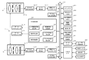
図1は、本発明の実施形態に係る3D画像撮像装置(デジタルビデオカメラ)1(以下、単に「撮像装置1」という。)の内部構成の例を示すブロック図である。
FIG. 1 is a block diagram showing an example of the internal configuration of a 3D image capturing apparatus (digital video camera) 1 (hereinafter simply referred to as “
なお、説明及び理解の容易のため、本実施形態に係る撮像装置1は、左眼用の撮像部及び右眼用の撮像部の二つの撮像部を有しており両撮像部の光軸が平行となるように固定され、両光軸のなす輻輳角を調整しないものとして以下を説明する。一方で、両撮像部を駆動し、両光軸のなす輻輳角を調整できる撮像装置においても本発明は採用できる。
For ease of explanation and understanding, the
また、本発明は、デジタルスチルカメラをはじめ、携帯電話、PHS(Personal Handyphone System)、PDA(Personal Digital Assistant)等、複数の撮像部を有し3D画像の撮像が可能なその他の電子機器においても採用することができる。 The present invention is also applicable to other electronic devices including a digital still camera, a mobile phone, a PHS (Personal Handyphone System), a PDA (Personal Digital Assistant), and the like that have a plurality of imaging units and can capture 3D images. Can be adopted.
中央制御部100は、CPU(Central Processing Unit)、各種プログラムが格納されたROM(Read Only Memory)、及びワークエリアとしてのRAM(Random Access Memory)等を含む半導体集積回路により構成され、撮像装置1の撮像処理、画像データの出力処理、又は表示処理等の各種処理を統括的に制御する。
The
撮像装置1には、左右一対の左眼用撮像部L110及び右眼用撮像部R110が、人間の両眼の間隔より少し短い所定の間隔(例えば6cm)離れて設置されている。
The
左眼用撮像部L110及び右眼用撮像部R110は、それぞれズームレンズL111及びR111、絞りL112及びR112、フォーカスレンズL113及びR113、並びに固体撮像素子L114及びR114を備える。 The left-eye imaging unit L110 and the right-eye imaging unit R110 include zoom lenses L111 and R111, diaphragms L112 and R112, focus lenses L113 and R113, and solid-state imaging devices L114 and R114, respectively.
ズームレンズL111及びR111は、それぞれズームアクチュエータL115及びR115によって光軸AL及びARに沿って移動する。フォーカスレンズL113及びR113は、図示しないフォーカスアクチュエータによって、同じく光軸AL及びARに沿って移動する。絞りL112及びR112は、図示しない絞りアクチュエータに駆動されて動作する。 Zoom lenses L111 and R111 are moved along optical axes AL and AR by zoom actuators L115 and R115, respectively. The focus lenses L113 and R113 are also moved along the optical axes AL and AR by a focus actuator (not shown). The diaphragms L112 and R112 operate by being driven by a diaphragm actuator (not shown).
撮像装置1を用いた3D画像の撮像は以下のような手順で行われる。左眼用固体撮像素子L114及び右眼用固体撮像素子R114がそれぞれ、左眼用撮像部L110と右眼用撮像部R110に入来した光を光電変換して、左右それぞれの被写体画像のアナログ撮像信号を生成する。
Imaging of a 3D image using the
アナログ信号処理部L116及びR116が、生成された左右それぞれの被写体画像のアナログ撮像信号を増幅した後、A/D変換器L117及びR117がそれら増幅されたアナログ撮像信号をデジタルの撮像データに変換する。 After the analog signal processing units L116 and R116 amplify the generated analog imaging signals of the left and right subject images, the A / D converters L117 and R117 convert the amplified analog imaging signals into digital imaging data. .
画像入力コントローラL118及びR118は、A/D変換機L117及びR117から出力されたデジタルの撮像データを取り込み、それらの撮像データはバス200に入力され、バス200を介してメインメモリ201に一時記憶される。
The image input controllers L118 and R118 capture digital image data output from the A / D converters L117 and R117, and the image data is input to the
デジタル信号処理部L119及びR119は、中央制御部100の指示に基づき、メインメモリ201に格納されたデジタルの撮像データを取り込み、所定の信号処理を施して輝度信号と色差信号とからなる信号を生成する。デジタル信号処理部L119及びR119はまた、オフセット処理、ホワイトバランス調整処理、ガンマ補正処理、RGB補完処理、ノイズ低減処理、輪郭補正処理、色調補正処理、光源種別判定処理等の各種デジタル補正を行う。
Based on instructions from the
メインメモリ201は、上述の3D画像の撮像で生成された左眼用撮像データ及び右眼用撮像データを一時記憶する。メインメモリ201は、例えばEPROM(Erasable Programmable Read Only Memory)、EEPROM(Electrically Erasable PROM)、不揮発性RAM、フラッシュメモリ、又はHDD(Hard Disk Drive)等の記憶媒体で構成される。
The
また、バス200を介して、フラッシュROM202、表示画像用メモリ203、画像処理部204、顔検出部205、及び圧縮・伸張処理部206が中央制御部100等と接続され、それぞれが以下に説明する機能を果たす。
A
フラッシュROM202は、ユーザの設定情報等、撮像装置1の動作に関する各種設定情報を格納している。例えば、撮像装置1は、左眼用画像と右眼用画像との間の視差調整に関する自動調整の設定内容や、カードI/F302や入出力I/F304に出力される左眼用出力画像データ及び右眼用出力画像データのアスペクト比に関するユーザの設定内容等を設定情報として格納している。
The
画像表示用メモリ203はVRAM(Video RAM)で構成され、液晶モニタ304等に表示される出力画像データやユーザが各種設定を行うためのメニュー画像データ等の各種画像データの一時記憶領域として使用される。
The
画像処理部204は、メインメモリ201から読み出したデジタルの撮像データに所定の画像処理を施す。例えば、画像処理部204は、出力される左眼用出力画像データ及び右眼用出力画像データのアスペクト比をユーザが選択したり、又は設定したりするための選択画像データやメニュー画像データを生成する。
The
そして、画像処理部204は、それら選択画像データ等をメインメモリ201から読み出されたオリジナルの撮像データに重畳させる等の画像処理を行う。これらの画像処理に係る画像データは画像表示用メモリ203に一時記憶された後、入出力I/F304を介して液晶モニタ306や入出力端子307に出力されることになる。
Then, the
顔検出部205は、中央制御部100からの指示に応じて、メインメモリ201に一時記憶された左眼用撮像データ及び右眼用撮像データから、被写体である人物の顔画像データを検出する。顔画像データの検出は、既知の方法により顔画像データ全体の輪郭または目、口、鼻、耳等の顔の構成要素のデータから特徴量を算出し、その特徴量に基づくテンプレートマッチングによって行われる。または、肌の色に近い領域データを検出し、その領域を顔画像データの領域として検出してもよい。検出された顔画像データは、後述する左眼用撮像データと右眼用撮像データとの間の視差の自動調整の処理に利用される。
In response to an instruction from the
圧縮・伸張処理部206は、中央制御部100の指示を受けて、メインメモリ201に記憶された各種データに所定形式の圧縮処理を施し、圧縮データを生成する。また、中央制御部100の指示を受けて、カード型記録媒体303等に格納された圧縮データに所定形式の伸張処理を施し、非圧縮データを生成する。なお、本実施の形態の撮像装置1では、静止画に対してはJPEG規格に準拠した圧縮方式が、動画に対してはMPEG2規格やAVC/H.264規格に準拠した圧縮方式が採用される。
In response to an instruction from the
メディア制御部301、カードI/F302、及び入出力I/F304もバス200を介して中央制御部100と接続され、以下の機能を果たす。
The
メディア制御部301は、中央制御部100の指示を受けて、カードI/F302を介してカード型記録媒体303へのデータの書き込みやカード型記録媒体303からのデータの読み出しを制御する。中央制御部100の指示に基づき、各種データがバス200を介してカードI/F302に入力され、カードI/F302はそれらのデータをカード型記録媒体303に出力する。
In response to an instruction from the
カード型記録媒体303としては、撮像装置1に着脱可能なSD(Secure Digital)メモリカード等が使用される。但し、これはあくまで例示であり、カード型記録媒体303の替りに、DVD、BD(Blu-ray Disc)、若しくはフラッシュメモリ等の他の記録媒体を使用する、又は撮像装置1に内蔵されたHDD(Hard Disc Drive)等で構成することができることはいうまでもない。
As the card-
また、各種データは、中央制御部100の指示を受けて、入出力I/F304に入力され、入出力I/F304はそれらのデータを液晶モニタ305又は入出力端子307に出力する。入出力I/F304には、液晶モニタ305、操作部306、及び入出力端子307が接続されている。ここで、液晶モニタ305は3D画像を表示し、観察者は表示された3D画像を裸眼にて観察できる態様となっている。
Various data are input to the input / output I /
図2は、この液晶モニタ305の水平方向の切断面を示す図である。
FIG. 2 is a diagram showing a horizontal cut surface of the
液晶モニタ305は、表示パネルの一例としての液晶パネルM21と、液晶パネルM21の表示面に対向して配置された視差分割部の一例としての液晶バリアM23とを備える。液晶パネルM21と液晶バリアM23は、粘着シートM22により接着されている。
The
液晶パネルM21において、液晶層M212の両面は液晶ガラス基板M211及びM213で挟まれ、表示面側の液晶ガラス基板M213にはカラーフィルタ(図示せず)が形成されている。 In the liquid crystal panel M21, both surfaces of the liquid crystal layer M212 are sandwiched between liquid crystal glass substrates M211 and M213, and a color filter (not shown) is formed on the liquid crystal glass substrate M213 on the display surface side.
カラーフィルタの主表面には、赤色(R)、緑色(G)、青色(B)の異なる色の着色層がマトリックス状に配置されている。この着色層の配置が液晶パネルM21の色画素の配置に対応している。液晶ガラス基板M213の表示面側には液晶偏光板M214が積層されている。液晶ガラス基板M211の裏面側にはバックライト(図示せず)が配置されている。 On the main surface of the color filter, colored layers of different colors of red (R), green (G), and blue (B) are arranged in a matrix. The arrangement of the colored layers corresponds to the arrangement of the color pixels of the liquid crystal panel M21. A liquid crystal polarizing plate M214 is laminated on the display surface side of the liquid crystal glass substrate M213. A backlight (not shown) is disposed on the back side of the liquid crystal glass substrate M211.
液晶バリアM23は、視差バリア(パララックスバリア)の一例であって、パッシブ方式液晶やアクティブマトリックス方式液晶によって光を遮断するバリア部のパターンを形成することができる。 The liquid crystal barrier M23 is an example of a parallax barrier (parallax barrier), and can form a pattern of a barrier portion that blocks light by a passive liquid crystal or an active matrix liquid crystal.
液晶バリアM23において、バリア液晶層M232の両面は液晶バリアガラス基板M231及びM233で挟まれている。液晶バリアガラス基板M233の表示面側には液晶バリア偏光板M234が積層されている。バリア液晶層M232には、光を遮断するバリア部M232aと光を透過するスリット部M232bとが交互に形成されている。 In the liquid crystal barrier M23, both surfaces of the barrier liquid crystal layer M232 are sandwiched between liquid crystal barrier glass substrates M231 and M233. A liquid crystal barrier polarizing plate M234 is laminated on the display surface side of the liquid crystal barrier glass substrate M233. In the barrier liquid crystal layer M232, barrier portions M232a that block light and slit portions M232b that transmit light are alternately formed.
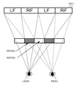
次に図3を参照して、観察者による液晶モニタ305に表示された3D画像の観察について説明する。図3は、観察者が液晶モニタ305に表示された左眼用画像及び右眼用画像を3D画像として認識する模様を説明するための概念図である。 Next, with reference to FIG. 3, the observation of the 3D image displayed on the liquid crystal monitor 305 by the observer will be described. FIG. 3 is a conceptual diagram for explaining a pattern in which the observer recognizes the left-eye image and the right-eye image displayed on the liquid crystal monitor 305 as a 3D image.
図3に示すように、観察者の右眼RE30からスリット部M232bを通じて視認される液晶パネルM21の右眼用色画素領域RFは、観察者の左眼LE30からはバリア部M232aによって遮蔽されて視認することができない。一方、観察者の左眼LE30からスリット部M232bを通じて視認される液晶パネルM21の左眼用色画素領域LFは、観察者の右眼RE30からはバリア部M232aによって遮蔽されて視認することができない。 As shown in FIG. 3, the color pixel region RF for the right eye of the liquid crystal panel M21 visually recognized from the observer's right eye RE30 through the slit part M232b is visually shielded from the observer's left eye LE30 by the barrier part M232a. Can not do it. On the other hand, the color pixel region LF for the left eye of the liquid crystal panel M21 visually recognized from the observer's left eye LE30 through the slit part M232b cannot be visually recognized by the observer's right eye RE30 because it is blocked by the barrier part M232a.
このように、液晶バリアM23は、液晶パネルM21の色画素領域を、右眼RE30の視線が届き、左眼LE30の視線が届かない右眼用色画素領域RFと、左眼LE30の視線が届き、右眼RE30の視線が届かない左眼用色画素領域LFとに分ける。これにより、水平方向に並ぶ観察者の右眼RE30及び左眼LE30の位置から異なる画像を見ることができる。 In this way, the liquid crystal barrier M23 reaches the color pixel area of the liquid crystal panel M21, the color pixel area RF for the right eye that the line of sight of the right eye RE30 reaches and the line of sight of the left eye LE30 does not reach, and the line of sight of the left eye LE30. And the left eye color pixel region LF where the line of sight of the right eye RE30 does not reach. Thereby, different images can be seen from the positions of the right eye RE30 and the left eye LE30 of the observer arranged in the horizontal direction.
すなわち、液晶パネルM21の画像を複数の視点方向に分割し、視認される画像を観察位置によって変化させることにより、観察者は液晶モニタ305に表示される左眼用画像及び右眼用画像を3D画像として認識することができる。
That is, by dividing the image on the liquid crystal panel M21 into a plurality of viewpoint directions and changing the visually recognized image according to the observation position, the observer 3D displays the image for the left eye and the image for the right eye displayed on the
なお、3D画像の表示のための液晶モニタ305の構造として、上述の通り視差バリア方式を用いた例を説明したが、他の方式、例えばレンチキュラ方式や光方向制御方式等を採用することもできる。また、液晶モニタ305は、ユーザが操作部306の図示しない操作ボタンにより、液晶バリアをON/OFFすることで、各種画像を3Dで表示するだけでなく、左眼用画像又は右眼用画像のいずれか一方を2Dで表示することもできる。また、左眼用画像及び右眼用画像の両方をいわゆるサイド・バイ・サイド方式で、二つ並べて2Dで表示することもできる。
Although the example using the parallax barrier method as described above has been described as the structure of the liquid crystal monitor 305 for displaying a 3D image, other methods such as a lenticular method and a light direction control method can also be adopted. . Further, the liquid crystal monitor 305 not only displays various images in 3D by turning on / off the liquid crystal barrier by an operation button (not shown) of the
操作部306は、図示しないリレーズ・スイッチや電源スイッチを含む各種操作ボタン、十字キー、ジョイスティック、又は液晶モニタ305上に重畳されたタッチパネル等から構成されており、ユーザの撮像装置1への操作入力を受け付ける。ユーザは操作部306の各種操作ボタン等を使用して、撮像装置1による撮像処理、各種設定、又はズームアクチュエータL116及びR116を駆動して、撮像画像の光学ズーム倍率の変更を実行する。
The
図1の説明に戻り、入出力端子307は、図示しない外部ディスプレイ装置やPC(Personal Computer)等の外部装置に接続される。入出力端子307は、例えばHDMI(High-Definition Multimedia Interface)端子、USB(Universal Serial Bus)端子、IEEE 1394規格に準拠した各種入力端子等で構成される。
後述する処理により左眼用撮像データから抽出された左眼用出力画像データ及び右眼用撮像データから抽出された右眼用出力画像データ等は、入出力端子307を介して、外部ディスプレイ装置等に出力される。
Returning to the description of FIG. 1, the input /
The output image data for the left eye extracted from the imaging data for the left eye and the output image data for the right eye extracted from the imaging data for the right eye by processing to be described later, an external display device, etc. Is output.
ここで、図4を参照して、上述の液晶モニタ305、又は入出力端子307に接続された外部ディスプレイ装置に表示される左眼用画像中の被写体画像と、それに対応する右眼用画像中の被写体画像との間の視差と、その被写体画像の飛び出しや引き込みの度合い等を説明する。
Here, referring to FIG. 4, the subject image in the left-eye image displayed on the liquid crystal monitor 305 or the external display device connected to the input /
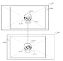
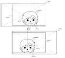
図4は左眼用画像中の被写体画像と右眼用画像中の被写体画像との間の視差と、その被写体画像の表示面に対する前方への飛び出しや後方への引き込み等の関係を説明するための概念図である。 FIG. 4 is a diagram for explaining the relationship between the parallax between the subject image in the left-eye image and the subject image in the right-eye image, and the projection of the subject image to the display surface and the pull-in to the rear. FIG.
図4において、左眼用画像データ及び右眼用画像データが表示される液晶モニタ307等の表示面をDP40、観察者の左眼をLE40、観察者の右眼をRE40、観察者の左眼LE40と右眼RE40との間隔をE、及び観察者と表示面DP40との間の距離をDとする。 In FIG. 4, the display surface of the liquid crystal monitor 307 or the like on which the left-eye image data and the right-eye image data are displayed is DP40, the left eye of the observer is LE40, the right eye of the observer is RE40, and the left eye of the observer The interval between the LE 40 and the right eye RE 40 is E, and the distance between the observer and the display surface DP 40 is D.
(前方へ飛び出しているかのように知覚される場合)
図4(a)において、表示面DP40上の左眼用画像中の被写体画像の位置をLf、右眼用画像中の被写体画像の位置をRfとすると、観察者が左眼LE40でLf、右眼RE40でRfを観察した場合、被写体画像はPfの位置で結像する。これにより観察者からは被写体画像が表示面DP40に対して前方に飛び出しているかのように知覚されることになる。
(When perceived as if jumping forward)
In FIG. 4A, when the position of the subject image in the left-eye image on the display surface DP40 is L f and the position of the subject image in the right-eye image is R f , the observer uses the left eye LE40 to display L. f , when R f is observed with the right eye RE 40, the subject image is formed at the position of P f . As a result, the viewer perceives the subject image as if it jumps forward with respect to the display surface DP40.
ここで、像LfとRfの水平方向の視差をVfとすると、表示面DP40から結像位置Pfまでの距離Zfは以下の式(1)の通りとなる。 Here, when the horizontal parallax of the image L f and R f and V f, the distance Z f from the display surface DP40 to the imaging position P f is as the following equation (1).
Zf=D・Vf/(E+Vf) ・・・(1) Z f = D · V f / (E + V f ) (1)
上記式(1)からわかる通り、像LfとRfの水平方向の視差をVfが大きくなるほど、表示面DP40から結像位置までの距離Zfは大きくなり、観察者から見て、被写体画像が表示面DP40に対して前方に飛び出しているかのように知覚される度合いも大きくなる。 As can be seen from the above equation (1), the greater the horizontal parallax of the image L f and R f is V f, a distance Z f from the display surface DP40 to the imaging position becomes larger, as viewed from the observer, the object The degree to which the image is perceived as if it is protruding forward with respect to the display surface DP40 also increases.
(表示面上にあるかのように知覚される場合)
図4(b)において、表示面DP40上の左眼用画像中の被写体の位置と、右眼用画像中の被写体の位置が同一となった場合、被写体画像は表示面D40上のPcの位置で結像する。これにより観察者からは被写体画像が表示面DP40上にあるかのように知覚されることになる。
(When perceived as if it is on the display surface)
In FIG. 4B, when the position of the subject in the left-eye image on the display surface DP40 and the position of the subject in the right-eye image are the same, the subject image is Pc on the display surface D40. The image is formed at the position. As a result, the viewer perceives the subject image as if it were on the display surface DP40.
(後方へ引き込んでいるかのように知覚される場合)
図4(c)において、表示面DP40上の左眼用画像中の被写体画像の位置をLb、右眼用画像中の被写体画像の位置をRbとすると、観察者が左眼LE40でLb、右眼RE40でRbを観察した場合、被写体はPbの位置で結像する。これにより観察者からは被写体画像が表示面DP40に対して後方に引き込んでいるかのように知覚されることになる。
(When perceived as if pulling backward)
In FIG. 4C, when the position of the subject image in the left-eye image on the display surface DP40 is L b , and the position of the subject image in the right-eye image is R b , the observer is L with the left eye LE40. b, when observing the R b in the right eye RE40, subject imaged at the position of P b. As a result, the observer perceives the subject image as if it is drawn backward with respect to the display surface DP40.
ここで、観察者の左眼LE40と右眼RE40の距離をE、像LfとRfの水平方向の視差をVbとすると、表示面DP40から結像位置Pbまでの距離Zbは以下の式(2)の通りとなる。 Here, the distance of the observer's left eye LE40 and right eye RE40 E, when the horizontal parallax of the image L f and R f and V b, the distance Z b from the display surface DP40 to the image forming position P b The following formula (2) is obtained.
Zb=D・Vb/(E−Vb) ・・・(2) Z b = D · V b / (E−V b ) (2)
上記式(2)からもわかる通り、像LbとRbの水平方向の視差をVbが大きくなるほど、表示面DP40から結像位置までの距離Zbは大きくなり、観察者から見て被写体画像が表示面DP40に対して後方に引き込んでいるかのように知覚される度合いも大きくなる。 As understood from the above equation (2), the larger the horizontal parallax of the image L b and R b is V b, the distance Z b from the display surface DP40 to the imaging position becomes larger, the object as viewed from the observer The degree to which an image is perceived as if it is pulled backward with respect to the display surface DP40 also increases.
以上のように、3D画像の表示においては、左眼用画像中の被写体画像と、それに対応する右眼用画像中の被写体画像との間の水平方向の視差の大きさに応じて、その被写体が表示面に対し飛び出しているように知覚されるのか、表示面上にあるかのように知覚されるのか、又は後方に引き込んでいるかのように知覚されるのかの別、及び飛び出しているように知覚される場合における飛び出しの度合い、又は引き込んでいるかのように知覚される場合の引き込みの度合いが決定される。 As described above, in the display of the 3D image, the subject is selected according to the size of the parallax in the horizontal direction between the subject image in the left-eye image and the corresponding subject image in the right-eye image. Whether it is perceived as popping out of the display surface, as if it is on the display surface, or as if pulling backwards The degree of popping out when perceived by the user or the degree of retraction when perceiving as if pulling in is determined.
図1の説明に戻り、中央制御部100は、撮像処理等の統括制御の他に、出力画像領域決定部101、視差算出部102、視差調整部103、撮像情報記録部104、アスペクト比判定部105、及びアスペクト比保持部106としても機能する。以下にそれぞれの機能について詳述する。
Returning to the description of FIG. 1, the
出力画像領域決定部101は、メインメモリ201に記録された左眼用撮像データ及び右眼用撮像データから、カードI/F302又は入出力I/F304への出力のために抽出される出力画像データの領域、すなわちアスペクト比、領域サイズ、及びそれぞれの撮像データ中における位置、を決定する。
The output image
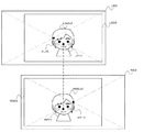
図5及び図6を参照して、この出力画像領域決定部101による出力画像データのアスペクト比、領域サイズ、及び位置の決定の処理について説明する。図5は撮像装置1による撮像の様子を示す模式図である。図6は、メインメモリ201に一時記憶された左眼用撮像データとそこから抽出される左眼用出力画像データ、及び右眼用撮像データとそこから抽出される右眼用出力画像データについて説明するための概念図である。
With reference to FIGS. 5 and 6, the process of determining the aspect ratio, region size, and position of the output image data by the output image
図5の模式図に示すように左眼用撮像部L110により被写体50を含む画角VL50内の人物や各種風景等が撮像画像として撮像され、右眼用撮像部R110により被写体50を含む画角VR50内の人物や各種風景等が撮像画像として撮像される。 As shown in the schematic diagram of FIG. 5, a person or various scenery in the angle of view VL50 including the subject 50 is captured as a captured image by the left-eye imaging unit L110, and the angle of view including the subject 50 is captured by the right-eye imaging unit R110. A person in the VR 50, various landscapes, and the like are captured as captured images.
そして図6に示すように、左眼用撮像部L110の画角VL50内の撮像画像に係る左眼用撮像データLI01、及び右眼用撮像部R110の画角VR50内の撮像画像に係る右眼用撮像データRI01が、メインメモリ201に一時記憶される。
As shown in FIG. 6, the left-eye imaging data LI01 related to the captured image within the angle of view VL50 of the left-eye imaging unit L110 and the right-eye related to the captured image within the angle of view VR50 of the right-eye imaging unit R110. Imaging data RI01 is temporarily stored in the
上述の通り、左眼用撮像部L110と右眼用撮像部R110とは水平方向に所定の間隔(例えば6cm)離れて設置されているため、左眼用撮像データLI01と右眼用撮像データRI01とは水平方向にずれる、すなわち水平方向の視差を有することになる。 As described above, since the left-eye imaging unit L110 and the right-eye imaging unit R110 are installed at a predetermined interval (for example, 6 cm) in the horizontal direction, the left-eye imaging data LI01 and the right-eye imaging data RI01 Deviates in the horizontal direction, that is, has a parallax in the horizontal direction.
例えば、図5に示すように、被写体50については、左眼用撮像部L110の光軸ALに対してはやや右側に、右眼用撮像部R110の光軸ARに対してはやや左側に位置するところで撮像されている。従って、図6に示すように左眼用撮像データLI01では被写体50の被写体画像データLOG50は中心より右側に、右眼用撮像データRI01では被写体画像データROG50は中心より左側に位置することになる。 For example, as shown in FIG. 5, the subject 50 is positioned slightly on the right side with respect to the optical axis AL of the left-eye imaging unit L110 and slightly on the left side with respect to the optical axis AR of the right-eye imaging unit R110. An image is being taken at the place. Accordingly, as shown in FIG. 6, in the left-eye imaging data LI01, the subject image data LOG50 of the subject 50 is located on the right side of the center, and in the right-eye imaging data RI01, the subject image data ROG50 is located on the left side of the center.
そして、出力画像領域決定部101は、左眼用撮像データLI01の中から抽出される左眼用出力画像データLO01のアスペクト比、領域サイズ、及び位置を決定し、右眼用撮像データRI01の中から抽出される右眼用出力画像データRO01のアスペクト比、領域サイズ、及び位置を決定する。
Then, the output image
左眼用出力画像データLO01及び右眼用出力画像データRO01のアスペクト比は、操作部306の図示しない操作ボタン等を使用してユーザが設定することができる。
The aspect ratio of the left-eye output image data LO01 and the right-eye output image data RO01 can be set by the user using an operation button (not shown) of the
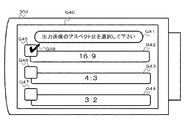
以下に、図7を参照して、左眼用出力画像データ及び右眼用出力画像データのアスペクト比の設定について説明する。図7は、ユーザが左眼用出力画像データ及び右眼用出力画像データを選択する際の、液晶モニタ304の表示を示す模式図である。 Hereinafter, setting of the aspect ratio of the output image data for the left eye and the output image data for the right eye will be described with reference to FIG. FIG. 7 is a schematic diagram showing a display on the liquid crystal monitor 304 when the user selects the output image data for the left eye and the output image data for the right eye.
画像処理部204が、ユーザに出力画像データのアスペクト比の選択を促す画像G41、出力画像のアスペクト比が16:9である旨を表示する画像G42,出力画像のアスペクト比が4:3である旨を表示する画像G43、出力画像のアスペクト比が3:2である旨の表示をする画像G44、画像G42からG44の選択を示すチェックボックス画像G45からG47が合成されたアスペクト比の設定画像G40を生成し、液晶モニタ304に表示する。
The
ユーザは設定画面G40に表示されたもの中から所望のアスペクト比を選択して、出力画像データのアスペクト比を設定する。ユーザは操作部306の図示しないタッチパネルを押圧する、又は図示しない十字キーと操作ボタンを操作する等して、チェックボックス画像G45からG47のいずれかを特定して、この選択を行う。
The user selects a desired aspect ratio from those displayed on the setting screen G40, and sets the aspect ratio of the output image data. The user specifies one of the check box images G45 to G47 by pressing a touch panel (not shown) of the
特定されたチェックボックス画像には、それが選択されたことを示すチェック画像G48を重畳され、チェックされていないチェックボックス画像との区別がなされる。図7では、ユーザが出力画像データのアスペクト比として縦と横の比が16:9のものを選択した場合の態様が表されている。ユーザが操作部307の図示しない操作ボタン等を使用して、選択内容を決定すると、アスペクト比の設定が完了する。
A check image G48 indicating that it has been selected is superimposed on the specified check box image to distinguish it from a check box image that has not been checked. FIG. 7 shows an aspect in which the user selects the aspect ratio of the output image data having a vertical / horizontal ratio of 16: 9. When the user uses the operation button (not shown) on the
なお、上述の図7及びその説明は、あくまでも一例であり、例えばユーザが操作部306の図示しない操作ボタン等を使用して、直接好みのアスペクト比を入力し、設定できるようにしてもよい。
Note that the above-described FIG. 7 and the description thereof are merely examples, and the user may directly input and set a preferred aspect ratio using an operation button (not illustrated) of the
図6の説明に戻り、上述のようにして設定されたアスペクト比及び別途ユーザが操作し設定する電子的なズーム倍率に応じて、左眼用出力画像データの領域の横辺Lh1及び縦辺Lv1、並びに右眼用出力画像データの領域の横辺Rh1及び縦辺Rv1が決定され、各出力画像データの領域サイズが決定される。 Returning to the description of FIG. 6, the horizontal side Lh1 and the vertical side Lv1 of the output image data area for the left eye according to the aspect ratio set as described above and the electronic zoom magnification separately operated and set by the user. The horizontal side Rh1 and the vertical side Rv1 of the output image data area for the right eye are determined, and the area size of each output image data is determined.
左眼用撮像データLI01内から抽出される左眼用出力画像データLO01の位置、及び右眼用撮像データRI01内から抽出される右眼用出力画像データRO01の位置として、後述する視差調整の処理を行わない場合は、中央制御部100のROMに記憶されている、例えば電子的な手ぶれ補正等を考慮した所定の位置が使用され、後述する視差調整の処理を行った場合は、その処理によって導出された位置が使用される。
Processing of parallax adjustment described later as the position of the output image data LO01 for the left eye extracted from the imaging data LI01 for the left eye and the position of the output image data RO01 for the right eye extracted from the imaging data RI01 for the right eye Is not performed, a predetermined position stored in the ROM of the
図1の中央制御部100の説明に戻り、視差算出部102は、以下のようにして左眼用撮像データと右眼用撮像データとの間の水平方向の視差を算出する。
Returning to the description of the
視差算出部102は、メインメモリ201に一時記憶された左眼用撮像データ及び右眼用撮像データから、両画像データにおける各被写体画像データ間の水平方向の視差(以下、単に「視差」ということもある。)を算出する。
The
視差算出部102による視差の算出は既知の様々な方法で行うことができるが、例えばMPEGにおける同一の被写体がフレーム間でどれだけ動いたかを特定する、いわゆる動きベクトルを算出するアルゴリズムを応用した方法により、左眼用撮像データの各被写体画像データと右眼用撮像データの各被写体画像データの差分ベクトルを算出する方法を使用する。
Although the parallax calculation by the
動画圧縮技術であるMPEGにおいては、ブロックマッチングに基づいて動きベクトルを検出するアルゴリズムが用いられる。ここで、動きベクトルとは2つのフレームデータ間における同一被写体の変位をベクトルで表したものである。現在のフレームデータと過去のフレームデータとを比較し、同一の大きさで最も類似したブロックをそれぞれから抽出し、両者の位置関係から動きベクトルを算出する。 In MPEG, which is a moving image compression technique, an algorithm for detecting a motion vector based on block matching is used. Here, the motion vector is a vector representing the displacement of the same subject between two frame data. The current frame data and past frame data are compared, the most similar blocks of the same size are extracted from each, and a motion vector is calculated from the positional relationship between them.
視差算出部102は、上記動きベクトル算出のアルゴリズムを利用して、左眼用撮像データ及び右眼用撮像データにおける同一被写体画像データを特定し、その同一被写体画像データについて、相互に対応する画素ブロックを左眼用撮像データ及び右眼用撮像データのそれぞれから抽出し、それらの差分ベクトルを左眼用撮像データ及び右眼用像データにおける被写体画像データの視差として算出する。
The
以下に図8を参照して、視差算出部102による視差の算出処理について説明する。図8は、視差算出部102による左眼用撮像データLI01と右眼用撮像データRI01との間の水平方向の視差の算出の一例として、顔検出部205が顔画像データを検出した被写体画像データの水平方向の視差の算出について説明するための概念図である。
Hereinafter, the parallax calculation processing by the
まず、顔検出部205が、上述の方法により左眼用撮像データLO01中の被写体画像データLOG50から顔画像データの領域LFA70、及び右眼用撮像データRO01中の被写体画像データROG50から顔画像データの領域RFA70を検出する。
First, the
そして、視差算出部102は、左眼用撮像データLI01中の顔画像データの領域LFA70から基準となる画素ブロック(以下、「基準画素ブロック」という。)LP70を特定し、右眼用撮像データRME6中の顔画像データの領域RFA70から基準画素ブロックLP70に対応する画素ブロック(以下、「対応画素ブロック」という。)RP70を特定する。
Then, the
そして、基準画素ブロックLP70と対応画素ブロックRP70との間の水平方向の差分ベクトルV01を算出する。以上のように、特定の被写体画像について左眼用画像データと右眼用画像データとの間の視差を算出することで、特定の被写体画像を中心とした視差調整の処理が可能となる。 Then, a horizontal difference vector V01 between the reference pixel block LP70 and the corresponding pixel block RP70 is calculated. As described above, by calculating the parallax between the left-eye image data and the right-eye image data for a specific subject image, it is possible to perform parallax adjustment processing centered on the specific subject image.
また、視差算出部102は、左眼用撮像データ及び右眼用撮像データのそれぞれを複数の領域に分け(例えば、横方向に8分割し縦方向にも8分割した、計64領域に分ける。)、左眼用撮像データの各領域から基準画素ブロックを特定し、右眼用撮像データの各領域から対応画素ブロックを特定して、各領域毎に水平方向の視差を算出することもできる。このようにすることで、特定の被写体だけでなく、左眼用撮像データ及び右眼用撮像データの全体的な視差を算出することができる。
Further, the
図1の中央制御部100の説明に戻り、視差調整部103は、以下のようにして、視差算出部102が算出した水平方向の視差に基づき、表示される左眼用画像と右眼用画像との間の水平方向の視差を調整する。
Returning to the description of the
上述のようにして視差算出部102が、左眼用撮像データと右眼用撮像データとの間の水平方向の視差を算出すると、視差調整部103が、算出された視差に基づき、左眼用撮像データから抽出される左眼用出力画像データ及び右眼用撮像データから抽出される右眼用出力画像データの位置を水平方向にシフトさせることで表示される左眼用画像と右眼用画像との間の視差を調整する。
When the
以下に、図9を参照して、視差調整部103による水平方向の視差の調整について説明する。図9は、視差調整部103による水平方向の視差の調整の例として、顔検出部205が顔画像データを検出した左眼用撮像データ中の被写体画像データLOG50と右眼用撮像データ中の被写体画像データROG50との間の水平方向の視差をゼロにする視差調整について説明するための概念図である。
Below, with reference to FIG. 9, the parallax adjustment of the horizontal direction by the
図9に示すように、視差算出部102は、左眼用撮像データLI01中の基準ブロックLP70と右眼用撮像データRI01中の対応ブロックRP70との間の差分ベクトルV01を視差として算出している。
As shown in FIG. 9, the
視差調整部103は、算出された差分ベクトルV01の向きと大きさから左眼用出力画像データ及び右眼用出力画像データをシフトさせる向きと大きさを決定する。
The
すなわち、視差調整部103は、左眼用撮像データLI01では、視差調整前の左眼用出力画像データLO01(図9中では破線で示した領域)を、差分ベクトルV01と反対の向きに、差分ベクトルV01の大きさの1/2の大きさのLS1だけ位置をシフトさせた領域を新たな出力画像領域LO02とする。
That is, the
また、視差調整部103は、右眼用撮像データRI01では、視差調整前の出力画像データRO01(図9中では破線で示した領域)を、差分ベクトルV01の向きに、差分ベクトルV01の大きさの1/2の大きさのRS1だけ位置をシフトさせた領域を新たな出力画像領域ROE62とする。
Further, the
以上のように視差調整部103は、左眼用撮像データから抽出される左眼用出力画像データ及び右眼用撮像データから抽出される右眼用出力画像データの位置を水平方向にシフトさせ、新たな出力画像データの位置を決定することで、水平方向の視差を調整する。図9では、この視差調整により、左眼用出力画像データLO02中の被写体画像データLOG50と右眼用出力画像データRO02中の被写体画像データROG50との間の視差がゼロとなる。
As described above, the
図10に、顔検出部205が顔画像データを検出した左眼用撮像データ中の被写体画像データLOG50と右眼用撮像データ中の被写体画像データROG50との間の水平方向の視差をゼロに調整した後の左眼用出力画像データLO02と右眼用出力画像データRO02とを示す。
10, the parallax in the horizontal direction between the subject image data LOG50 in the left-eye imaging data and the subject image data ROG50 in the right-eye imaging data for which the
図10に示したように、左眼用出力画像データLO02における基準画素ブロックLP70と右眼用出力画像データRO02における対応画素ブロックRP70との視差はゼロとなる。これらの出力画像データが出力され、液晶モニタ304等にこれらの画像データに係る画像が表示されると、被写体50の被写体画像は丁度モニタ上にあるかのように、観察者に知覚されることになる。 As shown in FIG. 10, the parallax between the reference pixel block LP70 in the left-eye output image data LO02 and the corresponding pixel block RP70 in the right-eye output image data RO02 is zero. When these output image data are output and an image related to these image data is displayed on the liquid crystal monitor 304 or the like, the subject image of the subject 50 is perceived by the observer as if it were just on the monitor. become.
なお、図9では、被写体画像が表示面に対して飛び出しているかのように知覚される際に、その被写体画像を丁度表示面上にあるかのように知覚されるように視差を調整する場合について示している。逆に、被写体画像が表示面に対して引き込んでいるかのように知覚される際に、その被写体画像を丁度表示面上にあるかのように知覚されるように視差を調整する場合については、左眼用出力画像データを差分ベクトルの向きに、右眼用出力画像データを差分ベクトルの向きと反対の向きにシフトさせることになる。 In FIG. 9, when the subject image is perceived as if it is popping out of the display surface, the parallax is adjusted so that the subject image is perceived as if it is exactly on the display surface. Shows about. Conversely, when the subject image is perceived as if it is drawn on the display surface, the parallax is adjusted so that the subject image is perceived as if it were exactly on the display surface. The output image data for the left eye is shifted in the direction of the difference vector, and the output image data for the right eye is shifted in the direction opposite to the direction of the difference vector.
また、撮像装置1では、ユーザが操作部307の図示しない操作ボタン等を使用して、左眼用出力画像データ及び右眼用撮像画像データをシフトさせる向きと大きさを変更して、視差を調整することができる。
Further, in the
すなわち、液晶モニタ305上に設けた図示しないタッチパネル上にプラスとマイナスのボタンをそれぞれ設け、ユーザがプラスボタンを押圧すると、抽出される左眼用出力画像データを左眼用撮像データ内の左方向に、抽出される右眼用出力画像データを右眼用撮像データ内の右方向にシフトさせ、ユーザがマイナスボタンと押圧すると、左眼用出力画像データを左眼用撮像データ内の右方向に、右眼用出力画像データを右眼用撮像データ内の左方向にシフトさせ、それぞれ押圧された回数又は時間に応じてシフトの大きさを変化させることができる。これによりユーザが、液晶モニタ305に表示された3D画像を好みの視差に調整することができる。
That is, when a plus button and a minus button are respectively provided on a touch panel (not shown) provided on the
さらに、視差調整部103は、顔検出部205が顔画像データを検出した場合に、その顔画像データを有する被写体画像の視差がゼロとなるようにする、又は左眼用撮像データ及び右眼用撮像データそれぞれについて複数の領域毎に算出された視差のうち、所定の大きさを上回る視差を有する領域を所定の大きさの視差とするようにする、等の自動調整を行うこともできる。
Furthermore, when the
図1の中央制御部100の説明に戻り、視差調整部103が視差の調整を行うと、撮像情報記録部104は調整された視差に関する情報及びその視差調整を行った際の光学ズーム倍率を撮像情報としてメインメモリ201に記録する。
Returning to the description of the
調整された視差に関する情報としては、視差調整後の左眼用撮像データから抽出される左眼用出力画像データのアスペクト比、領域サイズ、及び位置、並びに右眼用撮像データから抽出される右眼用出力画像データのアスペクト比、領域サイズ、及び位置が記録される。ズーム倍率としては、ズームレンズL112及びR112による光学ズーム倍率がメインメモリ201に記録される。
As information about the adjusted parallax, the aspect ratio, the region size, and the position of the output image data for the left eye extracted from the left-eye imaging data after the parallax adjustment, and the right eye extracted from the right-eye imaging data The aspect ratio, area size, and position of the output image data for use are recorded. As the zoom magnification, the optical zoom magnification by the zoom lenses L112 and R112 is recorded in the
視差調整部103はまた、上述の視差調整を行った後、光学ズーム倍率が変更された場合に、上記撮像情報記録部105が記録した撮像情報に基づき、その光学ズーム倍率の変更に応じた視差の調整を行う。
The
この光学ズーム倍率の変更に応じた視差の調整について説明する前に、視差調整部102が左眼用画像と右眼用画像の視差の調整を行った後、光学ズーム倍率が変更された場合の問題について図11及び図12を参照して以下に説明する。
Before describing the parallax adjustment according to the change in the optical zoom magnification, the
図11は、視差調整部103により視差調整が行われた後の左眼用出力画像データと右眼用出力画像データ、及び左眼用撮像部L110の光軸ALと右眼用撮像部R110の光軸ARとの関係を示す概念図である。図11は、視差調整部102が左眼用撮像データLO01の基準画素ブロックLP70と右眼用撮像データRO01の対応画素ブロックRP70との間の視差がゼロとなるように、抽出される左眼用出力画像データLI02及び右眼用出力画像データRI02の位置を決定したところが示されている。
FIG. 11 illustrates the output image data for the left eye and the output image for the right eye after the parallax adjustment is performed by the
左眼用出力画像データLO02と右眼用出力画像データRO02とが図11の状態にあるとき、左眼用出力画像データLO02中の基準画素ブロックLP70と、右眼用出力画像データRO02中の基準画素ブロックRP70とは液晶モニタ305等上に表示される3D画像中で一致しており、これら二つの点が重なる位置で視差がゼロとなっている。以下では、この視差がゼロになる位置を輻輳位置と呼ぶこととする。 When the left-eye output image data LO02 and the right-eye output image data RO02 are in the state shown in FIG. 11, the reference pixel block LP70 in the left-eye output image data LO02 and the reference in the right-eye output image data RO02 The pixel block RP70 matches in the 3D image displayed on the liquid crystal monitor 305 or the like, and the parallax is zero at the position where these two points overlap. Hereinafter, the position where the parallax becomes zero is referred to as a convergence position.
左眼用出力画像データLO02及び右眼用出力画像データRO02が出力され、両出力画像データに係る画像がそれぞれ液晶モニタ304等に表示されると、それらの画像を観察する観察者からは、この輻輳位置を通り、両画像の垂直方向の辺に平行な線分上に、光軸が存在するかのように擬似的に認識する。 When the output image data LO02 for the left eye and the output image data RO02 for the right eye are output and the images related to the output image data are respectively displayed on the liquid crystal monitor 304 or the like, the observer who observes these images receives this A pseudo-recognition is made as if the optical axis exists on a line segment passing through the convergence position and parallel to the vertical side of both images.
一方で、ズームアクチュエータL116及びR116を駆動して、光学ズーム倍率を変更すると、メインメモリ201に一時記憶された左眼用撮像データLI01の中心AL10及び右眼用撮像データRI01の中心AR10を中心として倍率が変更されることになる。左眼用撮像部L110の光軸AL1がAL10の位置に、右眼用撮像部R110の光軸ARがAR10の位置に結像するためである。
On the other hand, when the zoom actuators L116 and R116 are driven to change the optical zoom magnification, the center AL10 of the left-eye imaging data LI01 and the center AR10 of the right-eye imaging data RI01 stored temporarily in the
以上のように、左眼用撮像データLME6中の左眼用出力画像データの位置、及び右眼用撮像データRME6中の右眼用出力画像データの位置を水平方向に変更すると、水平方向の視差を調整した場合、各撮像部のレンズの光軸と、各出力画像に対し擬似的に認識される光軸とが不一致となる。 As described above, when the position of the left-eye output image data in the left-eye imaging data LME6 and the position of the right-eye output image data in the right-eye imaging data RME6 are changed in the horizontal direction, the horizontal parallax Is adjusted, the optical axis of the lens of each imaging unit does not match the optical axis that is pseudo-recognized for each output image.
ここで、光学ズーム倍率を変更して、撮像画像を拡大すると、撮像データ内では、撮像部の光軸と一致する位置を中心に被写体画像が拡大されることになる。 Here, when the optical zoom magnification is changed and the captured image is enlarged, the subject image is enlarged around the position corresponding to the optical axis of the imaging unit in the imaging data.
図12に視差がゼロとなるように視差調整を行った被写体画像が光学ズームにより拡大された場合の撮像データについて説明するための図を示す。図12に示すように光学ズーム倍率を変更して、撮像画像を拡大した場合は、左眼用撮像データLI02内において被写体画像データLOG50がAL10を中心に拡大された被写体画像データLOG51が、右眼用撮像データRI02内において被写体画像データROG50がAR10を中心に拡大された被写体画像データROG51が、それぞれ生成される。 FIG. 12 is a diagram for explaining imaging data when a subject image that has been subjected to parallax adjustment so that the parallax is zero is enlarged by optical zoom. When the captured image is enlarged by changing the optical zoom magnification as shown in FIG. 12, the subject image data LOG51 obtained by enlarging the subject image data LOG50 around AL10 in the left-eye imaging data LI02 becomes the right eye. The subject image data ROG51 in which the subject image data ROG50 is enlarged around the AR10 in the imaging data RI02 is generated.
そして、被写体画像データLOG50の基準画素ブロックLP70に対応する被写体画像データLOG51の基準画素ブロックLP71と、被写体画像データROG50の対応画素ブロックRP70に対応する対応画素ブロックRP71との間に、視差V02が生じてしまうことになる。 A parallax V02 is generated between the reference pixel block LP71 of the subject image data LOG51 corresponding to the reference pixel block LP70 of the subject image data LOG50 and the corresponding pixel block RP71 corresponding to the corresponding pixel block RP70 of the subject image data ROG50. Will end up.
これにより、左眼用撮像データから抽出される左眼用出力画像データ及び右眼用撮像データから抽出される右眼用出力画像データの位置を調整することで視差を調整し、任意の被写体画像の視差がゼロとなるように視差調整を行っても、光学ズーム倍率を変更することで、その被写体画像に再び視差が生じてしまい、視差がゼロとなる輻輳位置は別のところに移ってしまう問題が生じる。 Thereby, the parallax is adjusted by adjusting the positions of the output image data for the left eye extracted from the imaging data for the left eye and the output image data for the right eye extracted from the imaging data for the right eye, and an arbitrary subject image Even if the parallax adjustment is performed so that the parallax of the image becomes zero, changing the optical zoom magnification causes the parallax to occur again in the subject image, and the convergence position where the parallax becomes zero moves to another place. Problems arise.
そこで、視差調整部103は、光学ズーム倍率の変更があった場合は、そのズーム倍率の変更に応じて、抽出される左眼用出力画像データ及び右眼用出力画像データのシフト量をさらに漸増させていくことで、光学ズーム倍率の変更に追従した視差調整を行う。
Therefore, when there is a change in the optical zoom magnification, the
以下に、図13を参照して、視差調整が行われた後に光学ズーム倍率が変更された場合に、そのズーム倍率の変更に追従した視差調整について説明する。図13では、光学ズーム倍率の変更により左眼用撮像データLI02中の被写体画像データLOG52の基準画素ブロックLP71と、右眼用撮像データRI02中の被写体画像データROG51の対応画素ブロックRP71との間に差分ベクトルV02が生じてしまうところを示している。 Hereinafter, with reference to FIG. 13, when the optical zoom magnification is changed after the parallax adjustment is performed, the parallax adjustment following the change in the zoom magnification will be described. In FIG. 13, by changing the optical zoom magnification, between the reference pixel block LP71 of the subject image data LOG52 in the left eye imaging data LI02 and the corresponding pixel block RP71 of the subject image data ROG51 in the right eye imaging data RI02. A place where the difference vector V02 is generated is shown.
視差調整時の光学ズーム倍率をZD1、視差調整後の光学ズーム倍率をZD2とし、光学ズーム倍率変更前の出力画像データのシフト量をS1とすると、光学ズーム倍率変更前の輻輳位置に対応する位置を光学ズーム倍率の変更後も輻輳位置とするための総シフト量S2は、以下の式(3)により算出される。 If the optical zoom magnification at the time of parallax adjustment is ZD1, the optical zoom magnification after parallax adjustment is ZD2, and the shift amount of the output image data before the optical zoom magnification change is S1, the position corresponding to the convergence position before the optical zoom magnification change The total shift amount S2 for setting the position as the convergence position even after the optical zoom magnification is changed is calculated by the following equation (3).
S2=S1×ZD2/ZD1 ・・・(3) S2 = S1 × ZD2 / ZD1 (3)
従って、図13では、光学ズーム倍率変更前の輻輳位置に対応する位置を光学ズーム倍率の変更後も輻輳位置とするために、すなわち図11に示した光学ズーム倍率変更前の基準画素ブロックLP70に対応する光学ズーム倍率変更後の基準画素ブロックLP71と、図11に示した光学ズーム倍率変更前の対応画素ブロックRP70に対応する光学ズーム倍率変更後の対応画素ブロックRP71との間の差分ベクトルV02をゼロとするために、左眼用出力画像データLOE62(図13中では破線で示した領域)を差分ベクトルと反対の向きにLS2だけシフトさせた左眼用出力画像データLO03の位置、及び右眼用出力画像データRO02(図13中では破線で示した領域)を差分ベクトルの向きにRS2だけシフトさせた右眼用出力画像データRO03の位置が決定される。 Therefore, in FIG. 13, in order to make the position corresponding to the convergence position before the optical zoom magnification change the convergence position even after the optical zoom magnification change, the reference pixel block LP70 before the optical zoom magnification change shown in FIG. A difference vector V02 between the corresponding reference pixel block LP71 after changing the optical zoom magnification and the corresponding pixel block RP71 after changing the optical zoom magnification corresponding to the corresponding pixel block RP70 before changing the optical zoom magnification shown in FIG. The left-eye output image data L03 is shifted by LS2 in the direction opposite to the difference vector in order to make the left-eye output image data LOE62 (the region indicated by the broken line in FIG. 13), and the right-eye Output image data RO02 (region indicated by a broken line in FIG. 13) shifted by RS2 in the direction of the difference vector Position of the image data RO03 is determined.
ここで、LS2及びRS2のシフトの大きさΔSaは、以下の式(4)から導出される。 Here, the shift magnitude ΔSa of LS2 and RS2 is derived from the following equation (4).
ΔSa=S2−S1 ・・・(4) ΔSa = S2−S1 (4)
以上のように、ズームレンズL112及びR112の倍率の変更に追従して、視差調整部103が抽出される左眼用出力画像データ及び抽出される右眼用出力画像データの位置をシフトしていく。これによって、図14に示したよう被写体50の被写体画像データLOG52及びROG52の視差はゼロのまま維持され、撮像装置1は、ユーザが光学ズーム倍率を変更する前に意図した立体感を維持した3D画像を出力することができる。
As described above, following the change in the magnification of the zoom lenses L112 and R112, the position of the output image data for the left eye and the output image data for the right eye extracted by the
一方で、上述した様に左眼用撮像データから抽出される左眼用出力画像データ、及び右眼用撮像データから抽出される右眼用出力画像データを水平方向にシフトしていくことで、光学ズーム倍率の変更に応じた視差の調整を行った場合、メインメモリ201に一時記憶された撮像データに不足が生じ、出力画像データのアスペクト比を維持できない場合があるという問題が生じる。
On the other hand, by shifting the left-eye output image data extracted from the left-eye imaging data and the right-eye output image data extracted from the right-eye imaging data in the horizontal direction as described above, When the parallax adjustment is performed according to the change in the optical zoom magnification, there is a problem that the imaging data temporarily stored in the
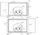
以下に図15を参照して、この光学ズーム倍率の変更に追従した視差調整において生じる撮像データの不足の問題について説明する。 Hereinafter, with reference to FIG. 15, a problem of lack of imaging data that occurs in the parallax adjustment following the change of the optical zoom magnification will be described.
図15に示すように、光学ズーム倍率が変更され被写体50の左眼用撮像データLI03中の被写体画像データLOG53の基準画素ブロックLP72と、右眼用撮像データRI03中の対応画素ブロックRP72との間に差分ベクトルV03が生じることとなった場合、上記式(4)に基づき左眼用出力画像データLO04をさらに右に、右眼用出力画像データRO04をさらに左にシフトさせなければ、基準画素ブロックLP72と対応画素ブロックRP72との間の視差をゼロに維持できない。 As shown in FIG. 15, between the reference pixel block LP72 of the subject image data LOG53 in the left-eye imaging data LI03 of the subject 50 and the corresponding pixel block RP72 in the right-eye imaging data RI03 as the optical zoom magnification is changed. When the difference vector V03 is generated in the reference pixel block, the output image data LO04 for the left eye is further shifted to the right and the output image data RO04 for the right eye is not further shifted to the left based on the above formula (4). The parallax between the LP 72 and the corresponding pixel block RP 72 cannot be maintained at zero.
しかし、図16に示すように、左眼用出力画像データLO04をLS4だけ右に、右眼用出力画像データRO04をRS4だけ右にシフトさせると、そもそも撮像データが取得されていない領域LLA01及びRLA01(図16でハッチングで示した領域)が生じることになる。 However, as shown in FIG. 16, when the left-eye output image data LO04 is shifted to the right by LS4 and the right-eye output image data RO04 is shifted to the right by RS4, regions LLA01 and RLA01 in which no imaging data has been acquired in the first place. (A region indicated by hatching in FIG. 16) occurs.
従って、図17に示すように、基準画素ブロックLP73と対応画素ブロックRP73との間の視差はゼロに維持できるものの、左眼用撮像データが取得されていない領域LLA01、及び右眼用撮像データが取得されていない領域RLA01が生じることから、左眼用出力画像データLO05(図17中で太線で囲った領域)及び右眼用出力画像データRO05(図17中で太線で囲った領域)を液晶モニタ305等に出力すると、表示される画像に不足分が生じ、出力される画像のアスペクト比はユーザが設定等したものと変わってしまうことになる。
Accordingly, as shown in FIG. 17, the parallax between the reference pixel block LP73 and the corresponding pixel block RP73 can be maintained at zero, but the area LLA01 in which the left-eye imaging data is not acquired and the right-eye imaging data are Since an unacquired region RLA01 occurs, the left-eye output image data LO05 (region surrounded by a thick line in FIG. 17) and the right-eye output image data RO05 (region surrounded by a thick line in FIG. 17) are liquid crystal. When output to the
そこで、図1の中央制御部100の説明に戻り、アスペクト比判定部106は、視差調整後に光学ズーム倍率が変更され、その光学ズーム倍率に視差調整を追従させる場合に、出力される出力画像データのアスペクト比が変更されるかどうかを判定する。
Returning to the description of the
具体的には、アスペクト比判定部106は、メインメモリ201に一時記憶されている撮像データ及びその撮像データ内の出力画像データの領域サイズと位置から、視差調整部102によるシフトを行うと、出力画像データに不足が生じるかどうかを判定することで、アスペクト比が変更されるかどうかを判定する。
Specifically, when the
そして、アスペクト比判定部106が、出力画像データのアスペクト比が変更されると判断した場合には、アスペクト比維持部107が、出力画像データの領域サイズを変更することで、光学ズーム倍率変更前のアスペクト比を維持する。
When the aspect
以下に、図18を参照して、アスペクト比維持部107が出力画像データの領域サイズを決定する処理について説明する。図18では、光学ズームの変更により、左眼用撮像データLI03中の基準画素ブロックLP72と、右眼用撮像データRI03中の対応画素ブロックRP72との間に差分ベクトルV03が生じることになる。 Hereinafter, with reference to FIG. 18, a process in which the aspect ratio maintaining unit 107 determines the area size of the output image data will be described. In FIG. 18, the difference vector V03 is generated between the reference pixel block LP72 in the left-eye imaging data LI03 and the corresponding pixel block RP72 in the right-eye imaging data RI03 due to the change in the optical zoom.
ここで、視差調整部103は、この差分ベクトルV03をゼロに維持するために必要な左眼用出力画像データのシフトの大きさLS4、及び右眼用出力画像データのシフトの大きさRS04を決定する。このLS04及びRS04の大きさΔSbは、上述の式(3)及び以下の式(5)から算出される。
Here, the
ΔSb=2(S2−S1) ・・・(5) ΔSb = 2 (S2-S1) (5)
出力画像データの領域サイズを変更する前の、左眼用出力画像データの水平方向の辺の長さをLh1とし、右眼用出力画像データの水平方向の辺の長さをRh1とすると、アスペクト比維持部107は、以下の式(6)及び式(7)から、領域サイズの変更された左眼用出力画像データLO06の水平方向の辺の長さLh2、及び領域サイズの変更された右眼用出力画像データRO06の水平方向の辺の長さRh2をそれぞれ算出する。 When the length of the horizontal side of the output image data for the left eye before changing the area size of the output image data is Lh1, and the length of the horizontal side of the output image data for the right eye is Rh1, The ratio maintaining unit 107 calculates the length Lh2 of the horizontal side of the output image data LO06 for the left eye whose region size has been changed and the right whose region size has been changed from the following equations (6) and (7). The horizontal side length Rh2 of the output image data RO06 for eyes is calculated.
Lh2=Lh1−LS4 ・・・(6) Lh2 = Lh1-LS4 (6)
Rh2=Rh1−RS4 ・・・(7) Rh2 = Rh1-RS4 (7)
Lh2及びRh2が算出されると、アスペクト比維持部107は、維持するアスペクト比となるように、領域サイズの変更された左眼用出力画像データLO06の垂直方向の辺の長さLv2、及び領域サイズの変更された右眼用出力画像データRO06の垂直方向の辺の長さRv2をそれぞれ算出する。以上のようにして、アスペクト比維持部107は、変更する出力画像データの領域サイズを決定し、光学ズーム倍率変更前のアスペクト比を維持する。 When Lh2 and Rh2 are calculated, the aspect ratio maintaining unit 107 calculates the length Lv2 of the side in the vertical direction of the output image data LO06 for the left eye whose region size has been changed so as to be the aspect ratio to be maintained, and the region The length Rv2 of the side in the vertical direction of the output image data RO06 for right eye whose size has been changed is calculated. As described above, the aspect ratio maintaining unit 107 determines the area size of the output image data to be changed, and maintains the aspect ratio before changing the optical zoom magnification.
そして、アスペクト比維持部106により領域サイズが決定された左眼用出力画像データLO06の左眼用撮像データLI03内における位置は、視差調整部103により差分ベクトルV03と反対の向きにLS4の大きさだけシフトさせた位置に決定される。また、アスペクト比維持部107により領域サイズが決定された右眼用出力画像データRO06の右眼用撮像データRI03内における位置は、視差調整部103により差分ベクトルV03の向きにRS4の大きさだけシフトさせた位置に決定される。
Then, the position in the left-eye imaging data LI03 of the left-eye output image data LO06 for which the region size has been determined by the aspect
そして、図19に示すように、基準画素ブロックLP72と対応画素ブロックRP72との間の水平方向の視差をゼロとしたまま、つまり輻輳位置を維持したままアスペクト比も維持された左眼用出力画像データLO06及び右眼用出力画像データRO06が出力される。 Then, as shown in FIG. 19, the left-eye output image in which the horizontal parallax between the reference pixel block LP72 and the corresponding pixel block RP72 is zero, that is, the aspect ratio is maintained while maintaining the convergence position. Data LO06 and right-eye output image data RO06 are output.
以上に述べたように、本発明の実施形態に係る撮像装置1によれば、左眼用画像と右眼用画像との間の視差が調整された後、光学ズーム倍率が変更された場合であっても、光学ズーム倍率が変更される前の出力される被写体画像の立体感及び出力される画像のアスペクト比を維持することができる。
As described above, according to the
次に、図20を参照して、撮像装置1による、左眼用画像と右眼用画像との間の視差が調整された後に光学ズーム倍率が変更された場合に、被写体画像の立体感及び画像のアスペクト比を維持する処理(方法)について説明する。
Next, with reference to FIG. 20, when the optical zoom magnification is changed after the parallax between the image for the left eye and the image for the right eye by the
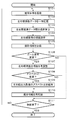
図20は、撮像装置1による、左眼用画像と右眼用画像との間の視差が調整された後に光学ズーム倍率が変更された場合の、被写体画像の立体感及び画像のアスペクト比を維持する処理を示すフローチャートである。
FIG. 20 shows the stereoscopic effect of the subject image and the aspect ratio of the image when the optical zoom magnification is changed after the parallax between the image for the left eye and the image for the right eye is adjusted by the
本処理は、ユーザが操作部306の図示しない録画ボタンを押したとき、図1に示した中央制御部100の統括制御によりプログラムに従い実行される。また、ユーザが撮像装置1の電源を入れ、操作部306の図示しないボタン等を使用して撮像モードを選択したとき、或は録画ボタンを半押しにしたときに取得されるスルー画像に対して本処理を開始するようにしてもよい。
This process is executed according to a program by the overall control of the
上述の通り、ズームアクチュエータL115及びR115が駆動され所定の光学ズーム倍率が設定された後、或は電源投入時に設定されていた光学ズーム倍率のまま、風景や被写体が左眼用撮像部L110及び右眼用撮像部R110を介して撮像される(ステップS101)。 As described above, after the zoom actuators L115 and R115 are driven and a predetermined optical zoom magnification is set, or with the optical zoom magnification set when the power is turned on, the landscape and the subject are captured by the left-eye imaging unit L110 and the right. Imaging is performed via the eye imaging unit R110 (step S101).
そして、撮像された風景や被写体は、左眼用固体撮像素子L114及び右眼用固体撮像素子R114を介して、左眼用撮像データ及び右眼用撮像データとして、メインメモリ201に一時記録される(ステップS102)。
The captured scenery and subject are temporarily recorded in the
次に視差算出部102が、ステップS102でメインメモリ201に一時記憶された左眼用撮像データと右眼用撮像データとの間の水平方向の視差を算出する(ステップS103)。
Next, the
ここで、視差算出部102は、上述の通り、動きベクトル算出のアルゴリズムを利用して、左眼用撮像データ及び右眼用撮像データにおける同一被写体画像データを特定し、その同一被写体画像データについて、相互に対応する画素ブロックを左眼用撮像データ及び右眼用撮像データのそれぞれから抽出し、それらの差分ベクトルを左眼用撮像データ及び右眼用像データにおける被写体画像データの視差として算出する。
Here, as described above, the
このとき、視差算出部102は、顔検出部205による顔画像データの検出結果を利用して、顔画像データが検出された被写体画像データについての水平方向の視差を算出する、又は左眼用撮像データ及び右眼用撮像データのそれぞれを複数の領域に分割し、左眼用画像データ及び右眼用画像データにおける各領域間の視差を算出することで、左眼用撮像データ及び右眼用撮像データの全体的な視差を算出することができる。
At this time, the
ステップS103で視差算出部102が左眼用撮像データと右眼用撮像データとの間の視差を算出すると、視差調整部103は、算出された視差に基づき、左眼用撮像データから抽出される左眼用出力画像データ、及び右眼用撮像データから抽出される右眼用出力画像データの位置を水平方向にシフトさせることで左眼用画像と右眼用画像との間の視差を調整する(ステップS104)。
When the
この視差調整部103による水平方向の視差の調整は、上述の通り、例えば顔検出部205が顔画像データを検出した場合に、その顔画像データを有する被写体画像の視差がゼロとなるようにする、又は左眼用撮像データ及び右眼用撮像データそれぞれについて複数の領域毎に算出された視差のうち、所定の大きさを上回る視差を有する領域を所定の大きさの視差とするようにする、等の自動調整により行うことができる。また、操作部306の図示しないタッチパネル等を用いることで、ユーザの手動調整により行うこともできる。
As described above, the parallax adjustment in the horizontal direction by the
ステップS104で視差調整部103が水平方向の視差を調整すると、撮像情報記録部104が、撮像情報記録部104は調整された視差に関する情報及びその視差調整を行った際の光学ズーム倍率を撮像情報として記録する(ステップS105)。
When the
調整された視差に関する情報としては、視差調整後の左眼用撮像データから抽出される左眼用出力画像データのアスペクト比、領域サイズ、及び位置、並びに右眼用撮像データから抽出される右眼用出力画像データのアスペクト比、領域サイズ、及び位置が記録される。ズーム倍率としては、ズームレンズL111及びR111による光学ズーム倍率がメインメモリ201に記録される。
As information about the adjusted parallax, the aspect ratio, the region size, and the position of the output image data for the left eye extracted from the left-eye imaging data after the parallax adjustment, and the right eye extracted from the right-eye imaging data The aspect ratio, area size, and position of the output image data for use are recorded. As the zoom magnification, the optical zoom magnification by the zoom lenses L111 and R111 is recorded in the
ステップS105で撮像情報が記録されると、視差調整部103は光学ズーム倍率が記録されたものから変更されたか否かを判定する(ステップS106)。そして光学ズーム倍率が変更された旨の判定がなされた場合は(ステップS106でYES)、視差調整部103は、そのズーム倍率の変更に応じて、左眼用出力画像データ及び右眼用出力画像データのシフト量をさらに漸増させていくことで、光学ズーム倍率の変更に追従した再度の視差調整を行う(ステップS107)。
When the imaging information is recorded in step S105, the
ステップS107における視差調整が行われると、アスペクト比判定部106は、出力される左眼用出力画像データ及び右眼用出力画像データのアスペクト比が変更されるか否かを判定する(ステップS108)。
When the parallax adjustment is performed in step S107, the aspect
具体的には、アスペクト比判定部106は、メインメモリ201に一時記憶されている撮像データ及びその撮像データから抽出される出力画像データの領域サイズと位置から、視差調整部102によるシフトを行うと、出力画像データに不足が生じるかどうかを判定することで、アスペクト比が変更されるかどうかを判定する。
Specifically, when the aspect
アスペクト比判定部105が、視差調整部102によるシフトを行うと出力画像データに不足が生じる旨の判定をし、出力画像データのアスペクト比が変更される旨の判定をすると(ステップS108でYES)、アスペクト比維持部106が、出力画像データの領域サイズを変更することで、光学ズーム倍率変更前のアスペクト比を維持する(ステップS109)。
If the aspect
アスペクト比維持部106による、維持すべきアスペクト比に基づく、左眼用出力画像データ及び右眼用出力画像データの領域サイズ及び位置の決定は、上述のようにして行われる。
The determination of the region size and position of the left-eye output image data and the right-eye output image data based on the aspect ratio to be maintained by the aspect
ステップS108でアスペクト比判定部105が、出力画像データのアスペクト比が変更されない旨の判定をした場合(ステップS108でNO)、又はステップS109でアスペクト比維持部106がアスペクト比を維持した出力画像データの領域サイズ及び位置を決定すると、撮像情報記録部104は、各ステップ完了後の、調整された視差に関する情報及びその視差調整を行った際の光学ズーム倍率を撮像情報として記録する(ステップS110)。
When the aspect
そしてステップS110における撮像情報の記録の後、又はステップS106で光学ズーム倍率が変更されなかった場合は(ステップS106でNO)、ユーザが操作部306の図示しない録画ボタンを離すと、中央制御部100の統括制御によりプログラムに従い撮影が終了される(ステップS111でYES)。又は、ユーザが撮像装置1の電源を切り、操作部306の図示しないボタン等を使用して撮影モードを解除したとき、或は半押しにした録画ボタンを離したとき、それまで取得されていたスルー画像に対する本処理を終了するようにしてもよい。
Then, after recording the imaging information in step S110 or if the optical zoom magnification has not been changed in step S106 (NO in step S106), when the user releases a recording button (not shown) of the
ユーザが撮影を終了しなかった場合は(ステップS111でNO)、再度ステップS101から同様の処理を繰り返す。 If the user has not finished shooting (NO in step S111), the same processing is repeated from step S101 again.
以上に述べたように、撮像装置1による、左眼用画像と右眼用画像との間の視差が調整された後に光学ズーム倍率が変更された場合に、被写体画像の立体感及び画像のアスペクト比を維持する処理(方法)によれば、光学ズーム倍率が変更された場合であっても、光学ズーム倍率が変更される前の出力される被写体画像の立体感及び出力される画像のアスペクト比を維持することができる。
As described above, when the optical zoom magnification is changed after the parallax between the image for the left eye and the image for the right eye by the
なお、上述の撮像装置1及び撮像装置1による処理の説明では、水平方向の視差の算出において、左眼用撮像データから基準画素ブロックを、右眼用撮像データから対応画素ブロックの特定を行い、左眼用撮像データと右眼用撮像データとの間の視差の算出を行なったが、この関係を逆としてもよい。
In the above description of the
すなわち、右眼用撮像データから基準画素ブロックを、左眼用撮像データから対応画素ブロックの特定を行い、左眼用撮像データと右眼用撮像データとの間の視差の算出を行なっても同様の効果を得られることは言うまでもない。 That is, the reference pixel block is identified from the right-eye imaging data, the corresponding pixel block is identified from the left-eye imaging data, and the parallax between the left-eye imaging data and the right-eye imaging data is calculated. It goes without saying that the effect of can be obtained.
また、説明及び理解の容易のため、撮像画像データ中における出力画像データの領域サイズ及び位置の決定において、左右の撮像部の垂直方向のずれを補正するための垂直方向のシフトや、電子的な手ぶれ補正のための出力画像データのシフトについての記載を省略したが、本発明はこれらと組み合わせることによっても実施可能であり、その効果を得ることができる。 Further, for ease of explanation and understanding, in the determination of the region size and position of the output image data in the captured image data, a vertical shift for correcting the vertical shift of the left and right imaging units, or electronic Although the description about the shift of the output image data for camera shake correction is omitted, the present invention can be implemented by combining with these, and the effect can be obtained.
100 中央制御部
101 出力画像領域決定部
102 視差算出部
103 視差調整部
104 撮像情報記録部
105 アスペクト比判定部
106 アスペクト比維持部
L110 左眼用撮像部
R110 右眼用撮像部
L111 左眼用ズームレンズ
R111 右眼用ズームレンズ
L115 左眼用ズームアクチュエータ
R115 右眼用ズームアクチュエータ
201 メインメモリ
205 顔検出部
302 カードI/F
303 カード型記録媒体
304 入出力I/F
305 液晶モニタ
306 操作部
307 入出力端子
DESCRIPTION OF
303 Card
305
Claims (4)
第二変倍レンズと、その第二変倍レンズを光軸に沿って駆動させる第二駆動部とを有し、第二撮影画像データを取得する第二撮像部と、
前記第一撮像データと前記第二撮像データとの間の視差を算出する視差算出部と、
前記視差算出部が算出した前記視差に基づき、前記第一撮像データから抽出する第一出力画像データの水平方向の位置、及び前記第二撮像データから抽出する第二出力画像データの水平方向の位置を調整することで、第一出力画像データと第二出力画像データとの間の水平方向の視差を調整する視差調整部と、
前記第一出力画像データ及び前記第二出力画像データの所定のアスペクト比を維持するアスペクト比維持部とを備え、
前記視差調整部による前記水平方向の視差の調整が行われた後に、前記第一駆動部により前記第一変倍レンズの倍率が変更され、かつ前記第二駆動部により前記第二変倍レンズの倍率が変更された場合に、
前記視差調整部は前記水平方向の視差の調整によって水平方向の視差がゼロとなっている被写体画像が前記倍率の変更後も水平方向の視差がゼロとなるように前記第一出力画像データの水平方向の位置、及び前記第二出力画像データの水平方向の位置を再度調整し、
前記アスペクト比維持部は前記第一出力画像データ及び前記第二出力画像データの領域サイズを変更することで、前記倍率の変更後もアスペクト比を維持する
ことを特徴とする3D画像撮像装置。 A first imaging unit that has a first variable magnification lens and a first drive unit that drives the first variable magnification lens along the optical axis;
A second imaging unit that has a second variable magnification lens and a second drive unit that drives the second variable magnification lens along the optical axis, and acquires second captured image data;
A parallax calculation unit that calculates parallax between the first imaging data and the second imaging data;
Based on the parallax calculated by the parallax calculation unit, the horizontal position of the first output image data extracted from the first imaging data, and the horizontal position of the second output image data extracted from the second imaging data A parallax adjustment unit that adjusts the parallax in the horizontal direction between the first output image data and the second output image data by adjusting
An aspect ratio maintaining unit that maintains a predetermined aspect ratio of the first output image data and the second output image data,
After the horizontal parallax adjustment is performed by the parallax adjustment unit, the magnification of the first zoom lens is changed by the first driving unit, and the second zooming unit of the second zoom lens is changed by the second driving unit. When the magnification is changed,
The parallax adjustment unit adjusts the horizontal direction of the first output image data so that the subject image in which the horizontal parallax is zero by adjusting the horizontal parallax is zero even after the magnification is changed. Adjust the position in the direction and the horizontal position of the second output image data again,
3. The 3D image capturing apparatus according to claim 1, wherein the aspect ratio maintaining unit maintains the aspect ratio even after the magnification is changed by changing a region size of the first output image data and the second output image data.
前記視差調整部は前記顔検出部が検出した顔画像データに基づき、前記第一撮像データから抽出する第一出力画像データの水平方向の位置、及び前記第二撮像データから抽出する第二出力画像データの水平方向の位置を調整することで、第一出力画像データと第二出力画像データとの間の水平方向の視差を調整することを特徴とする請求項1に記載の3D画像撮像装置。 A face detection unit for detecting human face image data from each of the first imaging data and the second imaging data;
The parallax adjustment unit is based on the face image data detected by the face detection unit, the horizontal position of the first output image data extracted from the first imaging data, and the second output image extracted from the second imaging data The 3D image capturing apparatus according to claim 1, wherein a horizontal parallax between the first output image data and the second output image data is adjusted by adjusting a horizontal position of the data.
前記視差調整部は前記入力された前記視差に基づき、前記第一撮像データから抽出する第一出力画像データの水平方向の位置、及び前記第二撮像データから抽出する第二出力画像データの水平方向の位置を調整することで、第一出力画像データと第二出力画像データとの間の水平方向の視差を調整することを特徴とする請求項1に記載の3D画像撮像装置。 An input unit that allows a user to input a desired parallax for the horizontal parallax between the first output image data and the second output image data,
The parallax adjustment unit, based on the input parallax, the horizontal position of the first output image data extracted from the first imaging data and the horizontal direction of the second output image data extracted from the second imaging data The 3D image capturing apparatus according to claim 1, wherein a horizontal parallax between the first output image data and the second output image data is adjusted by adjusting the position of the first output image data.
前記第一撮像データと前記第二撮像データとの間の視差を算出させ、
前記算出させた視差に基づいて、前記第一撮像データから抽出される第一出力画像データの水平方向の位置、及び前記第二撮像データから抽出される第二出力画像データの水平方向の位置を調整させる指示をコンピュータに実行させるプログラムであって、
前記第一出力画像データ及び前記第二出力画像データの水平方向の位置を調整した後に、前記第一駆動部により前記第一変倍レンズの倍率が変更され、かつ前記第二駆動部により前記第二変倍レンズの倍率が変更された場合に、
その水平方向の位置の調整により水平方向の視差がゼロとなっている被写体画像が前記倍率の変更後も水平方向の視差がゼロとなるように前記第一出力画像データの水平方向の位置、及び前記第二出力画像データの水平方向の位置を再度調整させて、
前記第一出力画像データ及び前記第二出力画像データの領域サイズを変更させて、前記倍率の変更後もアスペクト比を維持させる
ことを特徴とするプログラム。 The first imaging data having the first variable magnification lens and the first drive unit for driving the first variable magnification lens along the optical axis, the second imaging lens and the second variable magnification lens. A second imaging unit having a second driving unit that drives the lens along the optical axis, respectively, to acquire second imaging data;
Calculating the parallax between the first imaging data and the second imaging data;
Based on the calculated parallax, the horizontal position of the first output image data extracted from the first imaging data and the horizontal position of the second output image data extracted from the second imaging data are determined. A program for causing a computer to execute instructions for adjustment,
After adjusting the horizontal position of the first output image data and the second output image data, the magnification of the first variable magnification lens is changed by the first drive unit, and the second drive unit changes the first output image data and the second output image data. When the magnification of the double variable lens is changed,
The horizontal position of the first output image data so that the subject image in which the horizontal parallax is zero by adjusting the horizontal position is zero even after the magnification change, and Adjust the horizontal position of the second output image data again,
A program for changing an area size of the first output image data and the second output image data to maintain an aspect ratio even after the magnification is changed.
Priority Applications (1)
| Application Number | Priority Date | Filing Date | Title |
|---|---|---|---|
| JP2011122667A JP2012253452A (en) | 2011-05-31 | 2011-05-31 | 3d image imaging apparatus and program |
Applications Claiming Priority (1)
| Application Number | Priority Date | Filing Date | Title |
|---|---|---|---|
| JP2011122667A JP2012253452A (en) | 2011-05-31 | 2011-05-31 | 3d image imaging apparatus and program |
Publications (1)
| Publication Number | Publication Date |
|---|---|
| JP2012253452A true JP2012253452A (en) | 2012-12-20 |
Family
ID=47525886
Family Applications (1)
| Application Number | Title | Priority Date | Filing Date |
|---|---|---|---|
| JP2011122667A Withdrawn JP2012253452A (en) | 2011-05-31 | 2011-05-31 | 3d image imaging apparatus and program |
Country Status (1)
| Country | Link |
|---|---|
| JP (1) | JP2012253452A (en) |
Cited By (1)
| Publication number | Priority date | Publication date | Assignee | Title |
|---|---|---|---|---|
| WO2014147957A1 (en) * | 2013-03-21 | 2014-09-25 | パナソニック株式会社 | Image processing method and image processing device |
-
2011
- 2011-05-31 JP JP2011122667A patent/JP2012253452A/en not_active Withdrawn
Cited By (4)
| Publication number | Priority date | Publication date | Assignee | Title |
|---|---|---|---|---|
| WO2014147957A1 (en) * | 2013-03-21 | 2014-09-25 | パナソニック株式会社 | Image processing method and image processing device |
| CN105191300A (en) * | 2013-03-21 | 2015-12-23 | 松下知识产权经营株式会社 | Image processing method and image processing device |
| JP6016180B2 (en) * | 2013-03-21 | 2016-10-26 | パナソニックIpマネジメント株式会社 | Image processing method and image processing apparatus |
| US9986222B2 (en) | 2013-03-21 | 2018-05-29 | Panasonic Intellectual Property Management Co., Ltd. | Image processing method and image processing device |
Similar Documents
| Publication | Publication Date | Title |
|---|---|---|
| US10051258B2 (en) | Image processing device, image processing method and image processing computer program product | |
| CN102165785B (en) | Three-dimensional imaging device, method, and program | |
| US20120263372A1 (en) | Method And Apparatus For Processing 3D Image | |
| JP5420075B2 (en) | Stereoscopic image reproduction apparatus, parallax adjustment method thereof, parallax adjustment program, and imaging apparatus | |
| JP2011211381A (en) | Stereoscopic imaging apparatus | |
| CN103918249B (en) | Imaging device and imaging method | |
| CN102860015A (en) | Three-dimensional image capture device, image player device, and editing software | |
| WO2012023168A1 (en) | Stereoscopic image capturing device, and stereoscopic image capturing method | |
| US20140176686A1 (en) | Image processing device, image capturing apparatus, and method for adjusting disparity amount | |
| WO2011136137A1 (en) | Stereoscopic image pickup device and control method therefor | |
| WO2012105121A1 (en) | 3d video playing device, 3d video playing program and recording medium for same, 3d display device, 3d imaging device, and 3d video playing method | |
| JPWO2011162209A1 (en) | Image output apparatus, method and program | |
| US9154771B2 (en) | Apparatus for capturing stereoscopic image | |
| US8849012B2 (en) | Image processing apparatus and method and computer readable medium having a program for processing stereoscopic image | |
| WO2012105120A1 (en) | 3d video playing device, 3d video playing program, recording medium for same, 3d display device, 3d imaging device, and 3d video playing method | |
| JP5580486B2 (en) | Image output apparatus, method and program | |
| JP2012253452A (en) | 3d image imaging apparatus and program | |
| JP2012235281A (en) | Three-dimensional image photographing device and program | |
| WO2012001958A1 (en) | Image processing device, method and program | |
| JP2012227685A (en) | 3d image processing apparatus, 3d imaging apparatus, and program | |
| JP2012165207A (en) | Three-dimensional imaging apparatus | |
| JP2015029215A (en) | Stereoscopic image processing device | |
| JP5165742B2 (en) | Three-dimensional imaging apparatus, method, and program | |
| JP2012182786A (en) | Three-dimensional image pick-up device | |
| JP2013070154A (en) | Compound-eye imaging device and operation control method therefor |
Legal Events
| Date | Code | Title | Description |
|---|---|---|---|
| A300 | Withdrawal of application because of no request for examination |
Free format text: JAPANESE INTERMEDIATE CODE: A300 Effective date: 20140805 |