JP2012252046A - Cover opening/closing device and image forming apparatus - Google Patents
Cover opening/closing device and image forming apparatus Download PDFInfo
- Publication number
- JP2012252046A JP2012252046A JP2011122359A JP2011122359A JP2012252046A JP 2012252046 A JP2012252046 A JP 2012252046A JP 2011122359 A JP2011122359 A JP 2011122359A JP 2011122359 A JP2011122359 A JP 2011122359A JP 2012252046 A JP2012252046 A JP 2012252046A
- Authority
- JP
- Japan
- Prior art keywords
- cover
- rotating member
- lock member
- closing
- closing device
- Prior art date
- Legal status (The legal status is an assumption and is not a legal conclusion. Google has not performed a legal analysis and makes no representation as to the accuracy of the status listed.)
- Granted
Links
Images


Landscapes
- Electrophotography Configuration And Component (AREA)
Abstract
Description
本発明は、カバー開閉装置および画像形成装置に関し、さらに詳しくは、カバーを確実に閉じ状態に設定するための機構に関する。 The present invention relates to a cover opening / closing device and an image forming apparatus, and more particularly to a mechanism for reliably setting a cover in a closed state.
開閉可能なカバーを備えた装置の一つに画像形成装置がある。
画像形成装置は、画像形成に必要な処理を行うための装置類が筐体内に配備されており、保守時には筐体壁面の一部に設けられたカバーを開閉する場合がある。
開閉可能なカバーの支持構造には、ヒンジ軸を用いた構造が知られている(例えば、特許文献1)。
An image forming apparatus is one of apparatuses provided with an openable / closable cover.
In the image forming apparatus, devices for performing processing necessary for image formation are provided in a casing, and a cover provided on a part of the wall surface of the casing may be opened and closed during maintenance.
A structure using a hinge shaft is known as a cover support structure that can be opened and closed (for example, Patent Document 1).
この構造においては、オペレータの操作力によって開閉操作する場合の他に、開閉支点に回動習性を付与する弾性体を設けて開閉時の助力を付与する構成がある。
助力を付与する場合としては、カバーを開放する向きに付勢して開放を容易化するとともに、閉じる際には、その付勢に抗してカバーを閉じ操作することにより確実に閉じた状態を認識できるようにすることを意図することがある。
In this structure, in addition to the case of opening and closing by the operating force of the operator, there is a configuration in which an elastic body that imparts turning habits is provided at the opening and closing fulcrum to provide assistance during opening and closing.
In order to give assistance, the cover is urged in the opening direction to facilitate the opening, and when closing, the cover is closed by operating the cover against the urging. May be intended to be recognizable.
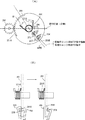
図9は、開放する向きに付勢する構成を用いた従来例を示す図であり、同図において、カバーKは、ヒンジ軸KA1を支点として揺動することにより開閉できるようになっている。
ヒンジ軸KA1には、巻き方向一端がカバー側にて係止され、巻き方向他端側がカバーを備えた装置本体側に係止されている弦巻バネなどの弾性体Bが捲装されている。
FIG. 9 is a diagram showing a conventional example using a configuration for biasing in the opening direction. In FIG. 9, the cover K can be opened and closed by swinging around the hinge axis KA1.
The hinge shaft KA1 is equipped with an elastic body B such as a string spring that has one end in the winding direction locked on the cover side and the other end in the winding direction locked on the apparatus main body side provided with the cover.
一方、カバーKの揺動端側には、装置本体側に設けられている係止ピンCLに対して揺動することにより係脱可能な係止レバーLBが設けられており、係止ピンCLに係止レバーLBが係合することによりカバーKの閉じ状態を維持することができるようになっている。 On the other hand, on the swing end side of the cover K, a lock lever LB that can be engaged and disengaged by swinging with respect to a lock pin CL provided on the apparatus main body side is provided. The closed state of the cover K can be maintained by engaging the locking lever LB.
カバーKを開放する際には、係止レバーLBと係止ピンCLとの係合を解除したうえで、開放する向きにカバーKを揺動させると、弾性体Bの付勢によりほぼ自動的にカバーKを開放することができる。 When opening the cover K, the engagement between the locking lever LB and the locking pin CL is released, and then the cover K is swung in the opening direction, so that the elastic body B is biased almost automatically. The cover K can be opened.
図9に示した構成においては、カバーKの開放に際しては、操作力の負担を軽減できる反面、図9(B)に示すように、係止レバーLBがカバーKの揺動方向と直角な方向に相当する幅方向両側に設けられている場合に幅方向片側のみしか係合状態が得られない、いわゆる、片閉まりと称される現象が発生する場合がある。つまり、幅方向片側が浮き上がってしまい係止できない状態となる。 In the configuration shown in FIG. 9, when the cover K is opened, the burden of operating force can be reduced, but the locking lever LB is perpendicular to the swinging direction of the cover K as shown in FIG. 9B. In the case where it is provided on both sides corresponding to the width direction, an engagement state can be obtained only on one side in the width direction, so-called a phenomenon called single closing may occur. That is, one side in the width direction is lifted and cannot be locked.
つまり、カバーKを閉じる際に幅方向両側に均等な閉じ力を与えた場合には、係止ピンCLと係止レバーLBとの係合が幅方向両側にて行われるものの、幅方向片側のみに閉じ力を付与した場合には、閉じ力が付与された側のみにおいて係合状態が得られてしまうことがある。 That is, when a uniform closing force is applied to both sides in the width direction when closing the cover K, the engagement between the locking pin CL and the locking lever LB is performed on both sides in the width direction, but only on one side in the width direction. In the case where a closing force is applied, the engaged state may be obtained only on the side where the closing force is applied.
例えば、画像形成装置内の搬送経路を開放するために設けられているカバーの場合には、幅方向中央側に搬送路が位置することが多く、このため、係止レバーの位置は幅方向両側となることが多い。このため、幅方向中央に閉じ力を与えた場合には幅方向両側への力が作用するものの、幅方向片側のみに閉じ力を与えると、カバーの幅方向で閉じ力が与えられない側が浮き上がったりして係止ピンと係止レバーとの係合が不完全となる虞がある。 For example, in the case of a cover provided to open the conveyance path in the image forming apparatus, the conveyance path is often located on the center side in the width direction. Often. For this reason, when a closing force is applied to the center in the width direction, a force is exerted on both sides of the width direction. However, if a closing force is applied to only one side in the width direction, the side where the closing force is not applied in the width direction of the cover will rise As a result, the engagement between the locking pin and the locking lever may be incomplete.
本発明の目的は、上記従来のカバー開閉装置における問題に鑑み、確実に閉じ状態を得られるようにして片閉まり現象の発生を確実に防止することができる構成を備えたカバー開閉装置および画像形成装置を提供することにある。 An object of the present invention is to provide a cover opening / closing apparatus and an image forming apparatus having a configuration capable of reliably preventing the occurrence of a one-side closing phenomenon by reliably obtaining a closed state in view of the problems in the conventional cover opening / closing apparatus. To provide an apparatus.
この目的を達成するため、本発明は次の構成よりなる。
(1)開閉可能なカバーと同軸支持されて回転可能な回転部材と、
前記カバーに設けられて前記回転部材に対して係脱可能な駆動用ロック部材と、
前記カバーの近傍に位置する不動部に設けられて前記回転部材に対し係脱可能な保持用ロック部材と、
前記回転部材に対して前記カバーの閉じ方向に付勢する弾性体と、
前記回転部材に付設されたダンパ部材とを備え、
前記駆動用ロック部材と前記保持用ロック部材とは、前記回転部材の回転角度が所定角度に達した時点で相互に係脱状態が切り換えられる関係を設定され、
前記カバーが閉じられる際に、前記保持用ロック部材の係合が解除されるのに応じて前記駆動用ロック部材が係合し、前記弾性体の付勢によりカバーの閉じ位置への移動が前記ダンパ部材によって緩衝されながら進行することを特徴とするカバー開閉装置。
In order to achieve this object, the present invention has the following configuration.
(1) a rotatable member that is coaxially supported and rotatable with an openable / closable cover;
A drive locking member provided on the cover and detachable from the rotating member;
A holding lock member which is provided in a stationary part located in the vicinity of the cover and is detachable with respect to the rotating member;
An elastic body biasing the rotating member in the closing direction of the cover;
A damper member attached to the rotating member,
The driving lock member and the holding lock member are set to have a relationship in which the disengagement state is switched between each other when the rotation angle of the rotation member reaches a predetermined angle,
When the cover is closed, the drive lock member is engaged in response to the engagement of the holding lock member being released, and the movement of the cover to the closed position is performed by the urging of the elastic body. A cover opening and closing device that travels while being buffered by a damper member.
(2)前記ダンパ部材には、前記回転部材との間に一方向クラッチが介在されて連動可能であることを特徴とする(1)記載のカバー開閉装置。 (2) The cover opening and closing device according to (1), wherein a one-way clutch is interposed between the damper member and the rotating member so as to be interlocked.
(3)前記回転部材に付設されたダンパ部材は、回転部材の外周面に形成された歯部に噛み合いギヤを備え、該回転部材の歯部は、前記カバーが閉じ位置に達する前に前記ダンパー部材のギヤとの噛み合いを解除できる領域に形成されていることを特徴とする(1)又は(2)記載のカバー開閉装置。 (3) The damper member attached to the rotating member includes a meshing gear in a tooth portion formed on the outer peripheral surface of the rotating member, and the tooth portion of the rotating member is disposed on the damper before the cover reaches the closed position. The cover opening / closing device according to (1) or (2), wherein the cover opening / closing device is formed in a region where the meshing of the member with the gear can be released.
(4)請求項(1)乃至(3)のうちの一つに記載のカバー開閉装置を用いることを特徴とする画像形成装置。 (4) An image forming apparatus using the cover opening / closing device according to any one of claims (1) to (3).
本発明によれば、回転部材の回転角度が所定角度に達した時点でカバー側と連動する駆動用ロック部材と不動部側に位置する保持用ロック部材との係脱関係が切り換えられる。
これにより、カバーを閉じる際に保持用ロック部材が解除された時点で駆動用ロック部材が係合する関係として相互に係脱関係が得られる状態を設定すると、駆動用ロック部材の係合により弾性体からの回転部材への付勢を介してカバーを閉じ方向にほぼ自動的に移動させることができる。
しかも、カバーが閉じ位置に近づくと、ダンパ部材による制動作用により揺動速度が低下することになり、回転数とトルクとの関係により閉じ位置に到達する際のトルクを大きくしてカバーの揺動端を効率よく押さえて幅方向片側が浮き上がるような事態を防止できる。
According to the present invention, when the rotation angle of the rotating member reaches a predetermined angle, the engagement / disengagement relationship between the driving lock member interlocked with the cover side and the holding lock member positioned on the non-moving portion side is switched.
As a result, when the state in which the engagement / disengagement relationship is obtained as the relationship in which the drive lock member is engaged when the holding lock member is released when the cover is closed is set, the engagement of the drive lock member causes elasticity. The cover can be moved almost automatically in the closing direction through the biasing of the rotating member from the body.
In addition, when the cover approaches the closed position, the swing speed decreases due to the braking action by the damper member, and the cover swings by increasing the torque when reaching the closed position due to the relationship between the rotational speed and the torque. It is possible to prevent a situation where one end in the width direction is lifted up by efficiently holding the end.
以下、図示実施例により本発明を実施するための形態について説明する。
図一は、本発明によるカバー開閉装置が適用され卯が造形性装置を示す模式図であり、同図において、符号1は、画像形成装置本体を示している。
Hereinafter, embodiments for carrying out the present invention will be described with reference to illustrated embodiments.
FIG. 1 is a schematic view showing a formability device to which a cover opening / closing device according to the present invention is applied. In FIG. 1,
画像形成装置本体1には、筐体上部に画像情報を光学的に読み取る原稿読み込み部2が配置されている。
原稿読み込み部2に装備されている走査装置10に搭載される原稿Dからの画像情報が読み込まれると、その画像情報に応じた書き込み光が露光部3において露光光Lの出射により作像部4に配置されている感光体ドラム5において静電潜像が形成される。
In the image forming apparatus
When image information is read from the document D mounted on the
静電潜像は作像部4に設けられている現像装置によって可視像処理された後、転写紙に転写され、転写を受けた転写紙は、定着装置20に装備されている加熱ローラ21および加圧路ラー31によって挟持搬送される過程で熱と圧力により定着されて排出される。
転写紙Pは、複数のトレイなどの給紙部12〜14から選択されて転写位置に向け搬送される。
The electrostatic latent image is subjected to a visible image process by a developing device provided in the image forming unit 4, and then transferred to a transfer sheet. The transferred transfer sheet is heated by a
The transfer paper P is selected from the
このような画像形成装置1においては、給紙部からの搬送路Kに対してカバー100が開閉可能に設けられており、ジャムなどの発生時にカバー100を開放して搬送路を外部に露呈させることができるようになっている。
In such an
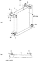
図2は、カバー100の構成を説明するための模式図であり、同図においてカバー100は、揺動支点となる回転軸101を揺動基端に有し、揺動端には装置本体内に設けられている係止ピン1Aに対して揺動することにより係脱可能な係止レバー102が備えられている。
FIG. 2 is a schematic diagram for explaining the structure of the
カバー100の揺動基端には、図3以降に示すカバー開閉装置200の主要部材が取り付けられている。
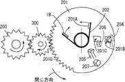
図3は、カバー開閉装置200の主要部の構成を説明するための模式図である。
同図においてカバー開閉装置200は、カバー100の回転軸101と同軸上に設けられている回転部材201と、回転部材201をカバー100の閉じ方向に付勢する弦巻バネなどの弾性体202と、回転部材201に付設されているダンパ部材203と、回転部材201の回転位置に応じて係脱可能な駆動用ロック部材204および保持用ロック部材205とを備えている。
The main member of the cover opening / closing device 200 shown in FIG. 3 and subsequent figures is attached to the swing base end of the
FIG. 3 is a schematic diagram for explaining a configuration of a main part of the cover opening / closing device 200.
In the figure, a cover opening / closing device 200 includes a rotating
以下、各部材について説明する。
回転部材201は、回転軸101と独立して回転できる状態に支持されている部材であり、表面に形成された係止部201Aに弾性体202の弦巻方向一端部が掛け止められている。
Hereinafter, each member will be described.
The rotating
弾性体202は、弦巻方向一端部が上述したように回転部材201側に掛け止められ、弦巻方向他端部が装置本体側の不動部に設けられている係止部1Bに掛け止められ、端部同士を接近させる方向の習性を持たせてある。このため、回転部材201は、図3において反時計方向に回転する習性が与えられており、この方向がカバー100を閉じる方向に相当させてある。
As described above, the
回転部材201の周面には、カバー100の閉じ位置から開放位置に亘る領域に相当する周長部分に歯部201Gが形成されており、この歯部201Aには、ダンパ部材203のギヤが噛み合っている。
ダンパ部材203は、減速ギヤを備えた緩衝部材であり、回転部材201の回転を減速する習性を備えている。
On the peripheral surface of the rotating
The
回転部材201の近傍には、駆動用ロック部材204,保持用ロック部材205を所定角度において相互に係脱関係を設定できる構成が設けられている。
各ロック部材204,205は、回転部材201側に揺動端を有する可撓性の樹脂部材であり、図3(B)を用いて後で説明するが、係合解除部材に乗り上げることで回転部材の係合部から離脱できるようになっている。なお、図3(B)では、駆動用ロック部材204が係合解除部材に乗り上げて回転部材の係合部から離脱する状態が示されている。
In the vicinity of the rotating
Each of the
つまり、回転部材210には、上記ロック部材毎に係脱できる係合孔201B,201Cが形成されており、この係合孔201B,201Cには、これらが所定角度の位置に回転した際に、ブロック部材のいずれかの係合を解除する解除部材206,207が対応させて設けられている。
That is, the rotation member 210 is formed with
駆動用ロック部材204を対象とする解除部材206は、不動部に設けられており、その設置位置は、カバーの全閉位置を初期位置(ホームポジション)として回転した場合にカバーの全開位置よりも手前側でロック部材204の係合を解除できる位置とされている。
The
一方、保持用ロック部材205を対象とする解除部材207は、カバー100側に設けられており、駆動用ロック部材294が係合孔201Bに再係合した際に保持用ロック部材205の係合を解除できる位置とされている。
On the other hand, the
これにより、カバー100が開放される際には、カバー100の全開位置の手前側にて駆動用ロック部材204が係合を解除されると、これに替わって保持用ロック部材205が係合孔201Cに係合することになる。
As a result, when the
このようなロック部材と回転部材側の係合孔との関係により、図4に示すように、カバー100が閉じ位置から開放する向きに揺動されると、カバー100の揺動に連動する駆動用ロック部材204が回転部材201をカバー100の開放方向に回転させることができ、全開位置に達する前には、図5(B)に示すように、駆動用ロック部材204が係合を解除されて保持用ロック部材205が係合する。保持用ロック部材205が係合すると、回転部材201の回転、つまり、弾性体202の付勢による閉じ方向の回転が抑止される。
Due to the relationship between the lock member and the engagement hole on the rotating member side, as shown in FIG. 4, when the
一方、カバー100が全開位置から全閉位置に向けて揺動されると、図6に示すように、駆動用ロック部材204が全開位置からある程度回転した時点で係合部201Bに再係合すると共に、図6(B)に示すように、保持用ロック部材206が係合を解除される。これにより、回転部材201に作用している弾性体202の付勢力が駆動用ロック部材204に伝達されてカバー100が閉じ方向に駆動される。
On the other hand, when the
上述したロック部材204,205は、図3(B)において駆動用ロック部材204を対象として説明すると、符号204Aで示すように、係合部201B内を貫通する傾斜部の長さ(L)が回転部材201の板厚(T)よりも大きくなる関係とされ、解除部材205により押し動かされた際に回転部材201の係合部201Bから確実に離脱できるようにされている。
When the
全開位置から、ある程度カバー100を閉じ方向に揺動させると前述したようにロック部材の係脱関係が切り替わり、特に、弾性体202の付勢を利用する状態となるので、オペレータが強制的にカバー100を閉じる際の労力負担を軽減することができる。
When the
カバー100が全閉位置に揺動する際には、ダンパ部材203による緩速作用により閉じ位置までの移動が緩やかに行われると共に、速度低下を回転数に置き換えた際のトルクとの関係から回転トルクが大きくなることで閉じ位置でのカバーの閉鎖力を強くでき、カバー100の幅方向片側が浮き上がるような事態を防止して片閉まりの発生をなくすことができる。
When the
次に本発明の要部変形例について説明する。
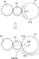
図7は、要部変形例を示す模式図であり、同図において、ダンパ部材203には回転部材201との間に一方向クラッチギヤ300が噛み合い関係を持たせるように配置されている。なお、図7に示す構成においては、各ロック部材及び係合部の構成は図3に示した場合と同様である。
Next, a modification of the main part of the present invention will be described.
FIG. 7 is a schematic diagram showing a modification of the main part. In FIG. 7, the one-way
一方向クラッチギヤ300は、回転部材201がカバー100の開放方向へ回転する際にはダンパ部材203との間に伝達関係をフリーな状態とし、回転部材201がカバー100の閉じ方向へ回転する際にはダンパ部材203の機能を発揮させるようになっている。図7では、閉じ方向に回転する際に回転部材201の回転が一方向クラッチギヤ300を介してダンパ部材203に伝達されている状態が示されている。
When the rotating
従って、カバー100を開放する際には、ダンパ部材203の機能が発揮されないので、迅速な開放が可能となり、カバー100を閉じる際には、上述した構成の場合と同様にダンパ部材203の機能を利用することができる。
Accordingly, since the function of the
このような構成においては、カバー100を開放する際に、軽い力で操作が可能となり、カバー100を閉じる際には、全開位置からある程度閉じると、弾性体の付勢を利用してほぼ自動的に閉じ位置に向け揺動させることができる。また、閉じ位置に到達する際には、緩速によるトルクの強さによって浮き上がりを防止されて片閉まりの発生が抑えられる。このように一方向クラッチギヤを用いることでカバー100の開放操作性を向上させることができる。
In such a configuration, when the
次に要部構成に関する他の例について説明する。
図8は、図7に示した一方向クラッチギヤ300を用いた場合を対象とする構成が示されている。
同図において回転部材201に形成されている歯部201Gは、カバー100が閉じ位置に到達する直前の時期に一方向クラッチギヤ300との噛み合いが解除される周長領域に形成されている。
Next, another example relating to the main configuration will be described.
FIG. 8 shows a configuration for the case where the one-way
In the drawing, the
つまり、カバー100が閉じ位置直前の位置まで揺動すると、ダンパ部材203の機能を伝達する一方向クラッチギヤ300と回転部材201側の歯との噛み合いが解除されるので(図8中、符号201GAで示す歯底円が露出している状態)、ダンパ部材203の機能が発揮できなくなる。これにより、カバー100の閉じ位置到達直前では、弾性体202の付勢を有効に用いることができるので、カバー100の閉じ力を増強することができる。これにより、閉じ位置でのカバー100の浮き上がりなどを防止して片閉まりが発生するのを防ぐことができる。
That is, when the
なお、回転部材201側の歯部201Gとの噛み合い解除に関しては、一方向クラッチギヤ300を用いないで、図3に示したように、ダンパ部材203との噛み合いを対象とすることも可能である。
In addition, regarding the release of meshing with the
1 画像形成装置
100 カバー
200 カバー開閉装置
201 回転部材
201B,201C 係合孔
202 弾性体
203 ダンパ部材
204,205 ロック部材
206,207 係合解除部材
DESCRIPTION OF
Claims (4)
前記カバーに設けられて前記回転部材に対して係脱可能な駆動用ロック部材と、
前記カバーの近傍に位置する不動部に設けられて前記回転部材に対し係脱可能な保持用ロック部材と、
前記回転部材に対して前記カバーの閉じ方向に付勢する弾性体と、
前記回転部材に付設されたダンパ部材とを備え、
前記駆動用ロック部材と前記保持用ロック部材とは、前記回転部材の回転角度が所定角度に達した時点で相互に係脱状態が切り換えられる関係を設定され、
前記カバーが閉じられる際に、前記保持用ロック部材の係合が解除されるのに応じて前記駆動用ロック部材が係合し、前記弾性体の付勢によりカバーの閉じ位置への移動が前記ダンパ部材によって緩衝されながら進行することを特徴とするカバー開閉装置。 A rotatable member that is coaxially supported and rotatable with an openable / closable cover;
A drive locking member provided on the cover and detachable from the rotating member;
A holding lock member which is provided in a stationary part located in the vicinity of the cover and is detachable with respect to the rotating member;
An elastic body biasing the rotating member in the closing direction of the cover;
A damper member attached to the rotating member,
The driving lock member and the holding lock member are set to have a relationship in which the disengagement state is switched between each other when the rotation angle of the rotation member reaches a predetermined angle,
When the cover is closed, the drive lock member is engaged in response to the engagement of the holding lock member being released, and the movement of the cover to the closed position is performed by the urging of the elastic body. A cover opening and closing device that travels while being buffered by a damper member.
Priority Applications (1)
| Application Number | Priority Date | Filing Date | Title |
|---|---|---|---|
| JP2011122359A JP5776335B2 (en) | 2011-05-31 | 2011-05-31 | Cover opening / closing device and image forming apparatus |
Applications Claiming Priority (1)
| Application Number | Priority Date | Filing Date | Title |
|---|---|---|---|
| JP2011122359A JP5776335B2 (en) | 2011-05-31 | 2011-05-31 | Cover opening / closing device and image forming apparatus |
Publications (2)
| Publication Number | Publication Date |
|---|---|
| JP2012252046A true JP2012252046A (en) | 2012-12-20 |
| JP5776335B2 JP5776335B2 (en) | 2015-09-09 |
Family
ID=47524948
Family Applications (1)
| Application Number | Title | Priority Date | Filing Date |
|---|---|---|---|
| JP2011122359A Expired - Fee Related JP5776335B2 (en) | 2011-05-31 | 2011-05-31 | Cover opening / closing device and image forming apparatus |
Country Status (1)
| Country | Link |
|---|---|
| JP (1) | JP5776335B2 (en) |
Citations (7)
| Publication number | Priority date | Publication date | Assignee | Title |
|---|---|---|---|---|
| JPS5851478U (en) * | 1981-09-30 | 1983-04-07 | パイオニア株式会社 | Door opening/closing reduction mechanism |
| JPH07320471A (en) * | 1994-05-25 | 1995-12-08 | Sony Corp | Operation range limiting buffer device |
| JPH10114352A (en) * | 1996-10-07 | 1998-05-06 | Brother Ind Ltd | Open lock mechanism of cover member |
| JP2004322429A (en) * | 2003-04-24 | 2004-11-18 | Sato Corp | Cover holder |
| JP2005059228A (en) * | 2003-08-12 | 2005-03-10 | Seiko Epson Corp | Memory protection device, electronic apparatus, and recording apparatus |
| JP2005074981A (en) * | 2003-09-04 | 2005-03-24 | Seiko Epson Corp | Lid body support device and recording device equipped with the same |
| JP2008055616A (en) * | 2006-08-29 | 2008-03-13 | Seiko Epson Corp | Cover opening and closing mechanism, covering apparatus, and electronic instrument |
-
2011
- 2011-05-31 JP JP2011122359A patent/JP5776335B2/en not_active Expired - Fee Related
Patent Citations (7)
| Publication number | Priority date | Publication date | Assignee | Title |
|---|---|---|---|---|
| JPS5851478U (en) * | 1981-09-30 | 1983-04-07 | パイオニア株式会社 | Door opening/closing reduction mechanism |
| JPH07320471A (en) * | 1994-05-25 | 1995-12-08 | Sony Corp | Operation range limiting buffer device |
| JPH10114352A (en) * | 1996-10-07 | 1998-05-06 | Brother Ind Ltd | Open lock mechanism of cover member |
| JP2004322429A (en) * | 2003-04-24 | 2004-11-18 | Sato Corp | Cover holder |
| JP2005059228A (en) * | 2003-08-12 | 2005-03-10 | Seiko Epson Corp | Memory protection device, electronic apparatus, and recording apparatus |
| JP2005074981A (en) * | 2003-09-04 | 2005-03-24 | Seiko Epson Corp | Lid body support device and recording device equipped with the same |
| JP2008055616A (en) * | 2006-08-29 | 2008-03-13 | Seiko Epson Corp | Cover opening and closing mechanism, covering apparatus, and electronic instrument |
Also Published As
| Publication number | Publication date |
|---|---|
| JP5776335B2 (en) | 2015-09-09 |
Similar Documents
| Publication | Publication Date | Title |
|---|---|---|
| JP5554981B2 (en) | Fixing apparatus and image forming apparatus | |
| JP6327219B2 (en) | Image forming apparatus | |
| JP6669037B2 (en) | Cover lock device, image forming device | |
| JP2013184754A (en) | Sheet conveyer, and image forming device | |
| JP4387345B2 (en) | Sheet conveying device, fixing device, and image forming apparatus | |
| JP2009190808A (en) | Paper feeder and image forming device | |
| JP4553028B2 (en) | Image forming apparatus | |
| JP2014191161A (en) | Image forming apparatus | |
| JP5522127B2 (en) | Image forming apparatus and power transmission mechanism | |
| JP2016098052A (en) | Recording medium conveyance device and image formation apparatus | |
| JP5776335B2 (en) | Cover opening / closing device and image forming apparatus | |
| JP2009132503A (en) | Sheet conveying apparatus | |
| JP5353796B2 (en) | Image forming apparatus | |
| JP2015189579A (en) | Image formation apparatus | |
| JP4681971B2 (en) | Image forming apparatus | |
| JP2006089165A (en) | Upper cover, sheet carrier and image forming device | |
| KR101308486B1 (en) | Image forming apparatus with coating function and Control method thereof | |
| JPH03148684A (en) | Fixing device | |
| JPH10236688A (en) | Jam disposal mechanism and image forming device | |
| JP2008145743A (en) | Transfer device, image forming apparatus using the same, and transfer device control method | |
| JP4205251B2 (en) | Image forming apparatus | |
| JP2015204545A (en) | image forming apparatus | |
| JP3883332B2 (en) | Image forming apparatus | |
| JP4824369B2 (en) | Paper transport device | |
| JP2011041034A (en) | Image reading apparatus and image forming apparatus |
Legal Events
| Date | Code | Title | Description |
|---|---|---|---|
| A621 | Written request for application examination |
Free format text: JAPANESE INTERMEDIATE CODE: A621 Effective date: 20140423 |
|
| A131 | Notification of reasons for refusal |
Free format text: JAPANESE INTERMEDIATE CODE: A131 Effective date: 20150324 |
|
| A977 | Report on retrieval |
Free format text: JAPANESE INTERMEDIATE CODE: A971007 Effective date: 20150325 |
|
| A521 | Request for written amendment filed |
Free format text: JAPANESE INTERMEDIATE CODE: A523 Effective date: 20150525 |
|
| TRDD | Decision of grant or rejection written | ||
| A01 | Written decision to grant a patent or to grant a registration (utility model) |
Free format text: JAPANESE INTERMEDIATE CODE: A01 Effective date: 20150609 |
|
| A61 | First payment of annual fees (during grant procedure) |
Free format text: JAPANESE INTERMEDIATE CODE: A61 Effective date: 20150622 |
|
| R151 | Written notification of patent or utility model registration |
Ref document number: 5776335 Country of ref document: JP Free format text: JAPANESE INTERMEDIATE CODE: R151 |
|
| LAPS | Cancellation because of no payment of annual fees |