JP2012251329A - Revolving type work machine - Google Patents
Revolving type work machine Download PDFInfo
- Publication number
- JP2012251329A JP2012251329A JP2011123307A JP2011123307A JP2012251329A JP 2012251329 A JP2012251329 A JP 2012251329A JP 2011123307 A JP2011123307 A JP 2011123307A JP 2011123307 A JP2011123307 A JP 2011123307A JP 2012251329 A JP2012251329 A JP 2012251329A
- Authority
- JP
- Japan
- Prior art keywords
- turning
- motor
- swing
- hydraulic
- pressure
- Prior art date
- Legal status (The legal status is an assumption and is not a legal conclusion. Google has not performed a legal analysis and makes no representation as to the accuracy of the status listed.)
- Granted
Links
Images
Abstract
Description
本発明はショベル等の旋回式作業機械に関するものである。 The present invention relates to a swivel work machine such as an excavator.
ショベルを例にとって背景技術を説明する。 The background art will be described using an excavator as an example.
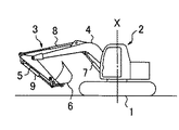
ショベルは、図5に示すようにクローラ式の下部走行体1上に上部旋回体2が地面に対して鉛直な軸Xまわりに旋回自在に搭載され、この上部旋回体2に掘削アタッチメント3が装着されて構成される。
As shown in FIG. 5, the excavator is mounted on a crawler-type lower traveling body 1 so that an upper swing body 2 can swing around an axis X perpendicular to the ground, and an
掘削アタッチメント3は、起伏自在なブーム4と、このブーム4の先端に取付けられたアーム5と、このアーム5の先端に取付けられたバケット6、それにこれらを作動させるブーム、アーム、バケット各シリンダ(油圧シリンダ)7,8,9によって構成される。
The
このショベルにおいて、上部旋回体2を旋回駆動する旋回駆動システムとして特許文献1に記載されたものが公知である。 In this excavator, a swing drive system described in Patent Document 1 is known as a swing drive system that swings the upper swing body 2.
この公知技術においては、駆動源としての旋回用油圧モータに電動機を接続するとともに、モータ両側管路とコントロールバルブとの間に、モータ両側管路を短絡可能な短絡切換弁を設け、旋回減速時に、短絡切換弁によりモータ吐出油をモータ入口側に戻すとともに、電動機に発電機作用を行わせて回生発電し、発生した回生電力を蓄電器に蓄える構成がとられている。 In this known technique, an electric motor is connected to a turning hydraulic motor as a drive source, and a short-circuit switching valve capable of short-circuiting the motor both-side pipes is provided between the motor both-side pipes and the control valve. In addition, the motor discharge oil is returned to the motor inlet side by the short-circuit switching valve, and the electric motor performs a generator action to generate regenerative power, and the generated regenerative power is stored in the capacitor.
この構成によると、短絡切換弁により旋回減速時にモータ出口側に作用する背圧を小さくして油圧モータの連れ回り負荷を低減し、これによって慣性運動エネルギーの回収(回生)効率を上げることができる。 According to this configuration, the back pressure acting on the motor outlet side when the vehicle is decelerated by the short-circuit switching valve is reduced to reduce the accompanying load of the hydraulic motor, thereby increasing the recovery (regeneration) efficiency of inertial kinetic energy. .
なお、この構成をとる場合、モータ両側管路間に設けられた一対のリリーフ弁等から成る油圧ブレーキ装置は、旋回減速時には働かず、旋回停止直後の停止保持機能のみを果たす。 When this configuration is adopted, the hydraulic brake device including a pair of relief valves provided between the motor both-side pipelines does not work at the time of turning deceleration and performs only the stop holding function immediately after the turning stop.
ところが、公知技術によると、上記のように旋回減速時の回生効率の向上には役立つが、旋回力行時、つまり起動を含む加速時及び定常運転時には回生作用は行われないため、旋回エネルギーの回生効率においてなお不十分であった。 However, according to the known technology, as described above, it helps to improve the regeneration efficiency during turning deceleration, but the regenerative action is not performed during turning power running, that is, during acceleration including start-up and steady operation. It was still insufficient in efficiency.
また、短絡切換弁は旋回力行時には開通位置にあり、回生時(減速時)に短絡位置に切換わるため、この切換わる瞬間に大きな圧力変動が生じ、この点で操作性が悪くなるという問題もあった。 In addition, the short-circuit switching valve is in the open position during turning power operation, and is switched to the short-circuit position during regeneration (during deceleration) .Therefore, a large pressure fluctuation occurs at the moment of switching, and the operability deteriorates at this point. there were.
そこで本発明は、旋回減速時だけでなく力行時にも回生作用を働かせて旋回エネルギーの回生効率を向上させることができ、しかも公知技術のような大きな圧力変動を無くして操作性を改善することができる旋回式作業機械を提供するものである。 Therefore, the present invention can improve the regenerative efficiency of the turning energy not only at the time of turning deceleration but also at the time of power running and improve the operability by eliminating the large pressure fluctuation as in the known art. Provided is a swivel type working machine.
上記課題を解決する手段として、本発明においては、下部走行体と、この下部走行体上に旋回自在に搭載された上部旋回体と、この上部旋回体の旋回駆動源としての旋回用の油圧モータと、この油圧モータにより回転駆動される旋回電動機と、蓄電器と、上記油圧モータの圧油供給源としての油圧ポンプと、旋回の加速、定常運転、減速、停止を指令する旋回操作手段と、この旋回操作手段の操作に基づいて上記油圧モータに対する圧油の給排を制御するコントロールバルブとを備えた旋回式作業機械において、上記旋回操作手段の操作を検出する旋回操作検出手段と、モータ出口側管路をタンクに連通させる連通位置とこの連通を遮断する連通遮断位置との間で作動する連通弁と、上記旋回操作検出手段からの信号に基づいて上記旋回電動機の回生作用及び上記連通弁の作動を制御する制御手段とを備え、上記制御手段は、上記上部旋回体の旋回動作時に、上記連通弁を連通位置にセットするとともに、この連通弁による背圧の低減分に相当する回生量を上記旋回電動機に指令する回生制御を行うように構成したものである。 As means for solving the above-mentioned problems, in the present invention, a lower traveling body, an upper swing body that is pivotably mounted on the lower traveling body, and a turning hydraulic motor as a swing drive source of the upper swing body A swing motor that is rotationally driven by the hydraulic motor, a capacitor, a hydraulic pump as a pressure oil supply source of the hydraulic motor, a swing operation means that commands acceleration, steady operation, deceleration, and stop of the swing, In a swing type work machine having a control valve for controlling supply and discharge of pressure oil to and from the hydraulic motor based on the operation of the swing operation means, a swing operation detection means for detecting the operation of the swing operation means, and a motor outlet side A communication valve that operates between a communication position for communicating the pipe line with the tank and a communication cutoff position for blocking the communication, and the swing electric motor based on a signal from the swing operation detecting means. Control means for controlling the regenerative action and the operation of the communication valve, and the control means sets the communication valve at the communication position during the turning operation of the upper-part turning body, and the back pressure generated by the communication valve. The regenerative control is performed so that the regenerative amount corresponding to the reduced amount is commanded to the swing electric motor.
このように、力行時、減速時を問わず、旋回動作中を通じて、連通弁により、モータ吐出油をタンクに戻すことによって背圧を低減し、この背圧低減分に相当するだけの回生電力を発生させる構成であるため、旋回力行時のポンプ動力を上げずに回生効率を向上させ、トータルでの省エネ効果を高めることができる。 In this way, the back pressure is reduced by returning the motor discharge oil to the tank by the communication valve regardless of whether it is powering or decelerating, and the regenerative power corresponding to this back pressure reduction is reduced. Since it is the structure to generate | occur | produce, regeneration efficiency can be improved without raising the pump power at the time of turning power running, and the total energy-saving effect can be heightened.
また、旋回動作中は、終始、連通弁を開いた状態とするため、特許文献1の技術のような切換弁の切換えによる圧力変動がなく、良好な操作性を確保することができる。 Further, since the communication valve is kept open throughout the turning operation, there is no pressure fluctuation due to switching of the switching valve as in the technique of Patent Document 1, and good operability can be ensured.
この場合、旋回速度を検出する旋回速度検出手段と、上記油圧モータの出口側圧力を検出する圧力検出手段とを設け、上記制御手段は、上記旋回操作手段の操作量によって決まる上記コントロールバルブのメータアウト開口面積と、旋回速度によって決まるモータ流量とから、上記連通弁が無いものとしたときのモータ出口側圧力を算出し、この算出値からモータ出口側圧力の検出値を引いて背圧の低減分を求めるように構成するのが望ましい(請求項2)。 In this case, a turning speed detecting means for detecting the turning speed and a pressure detecting means for detecting the outlet side pressure of the hydraulic motor are provided, and the control means is a meter of the control valve determined by an operation amount of the turning operation means. Calculate the motor outlet side pressure when there is no communication valve from the out opening area and the motor flow rate determined by the turning speed, and reduce the back pressure by subtracting the detected value of the motor outlet side pressure from this calculated value. It is desirable that the minutes be obtained (claim 2).
この構成によれば、背圧低減分を正確に割り出し、回生電力の過不足のない適正な回生制御を行うことができる。 According to this configuration, it is possible to accurately determine the amount of back pressure reduction and perform appropriate regenerative control without excessive or insufficient regenerative power.
ところで、旋回式作業機械においては、通常、旋回用油圧モータを含めた複数の油圧アクチュエータを一つの油圧ポンプで駆動する構成がとられる。 By the way, in a turning type work machine, the structure which drives several hydraulic actuators including the hydraulic motor for turning normally with one hydraulic pump is taken.
この構成において、旋回単独操作時には、元々、旋回力行中のポンプ圧がさほど高くならず、背圧も低い半面、この状態で回生作用を行わせるとポンプ圧が上昇するため、全旋回動作を通じたトータルでの省エネ効果が下がる可能性がある。 In this configuration, when turning alone, the pump pressure during turning power is not so high and the back pressure is low. On the other hand, if the regenerative operation is performed in this state, the pump pressure rises. The total energy saving effect may be reduced.
一方、複合操作時には、他の油圧アクチュエータの作動圧によってポンプ圧が上昇し、背圧低減のメリットも回生効率の向上効果も大きくなるため、トータルでの省エネ効果が高くなる。 On the other hand, during combined operation, the pump pressure increases due to the operating pressure of the other hydraulic actuators, and the merit of reducing the back pressure and the effect of improving the regeneration efficiency are increased, so the total energy saving effect is increased.
そこで、油圧ポンプを、旋回用の油圧モータを含む複数の油圧アクチュエータで共用する構成をとる場合に、上記制御手段は、上記旋回用の油圧モータのみが作動する旋回単独操作時には上記回生制御を行わず、上記旋回用の油圧モータと他の油圧アクチュエータとが同時に作動する複合操作時のみに上記回生制御を行うように構成するのが望ましい(請求項3)。 Therefore, when a configuration is adopted in which the hydraulic pump is shared by a plurality of hydraulic actuators including a turning hydraulic motor, the control means performs the regenerative control at the time of the turning single operation in which only the turning hydraulic motor operates. It is desirable that the regenerative control be performed only during the combined operation in which the turning hydraulic motor and the other hydraulic actuator are simultaneously operated.
このように回生制御を旋回単独操作時には行わず、複合操作時のみに行うことで省エネ効果を最大限に高めることができる。 As described above, the regenerative control is not performed at the time of the single turning operation, but is performed only at the time of the combined operation, so that the energy saving effect can be maximized.
本発明によると、旋回減速時だけでなく力行時にも回生作用を働かせて旋回エネルギーの回生効率を向上させることができ、しかも公知技術のような大きな圧力変動がなくて操作性を改善することができる。 According to the present invention, the regenerative action can be applied not only during turning deceleration but also during power running to improve the revolving efficiency of turning energy, and the operability can be improved without the large pressure fluctuation as in the known art. it can.
本発明の第1及び第2両実施形態を図1〜図4によって説明する。実施形態はショベルを適用対象としている。 First and second embodiments of the present invention will be described with reference to FIGS. The embodiment is applied to an excavator.
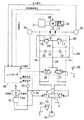
図1は両実施形態に係る旋回駆動システムの全体構成を示す。 FIG. 1 shows the overall configuration of a turning drive system according to both embodiments.
図1において、10は図示しないエンジンによって駆動される油圧源としての油圧ポンプ、11はこの油圧ポンプ10からの圧油により回転して図5の上部旋回体2を旋回駆動する旋回用の油圧モータで、油圧ポンプ10及びタンクTとこの油圧モータ11との間に、旋回操作手段としてのリモコン弁12(12aは操作用のレバーである)によって操作される油圧パイロット式の切換弁であるコントロールバルブ13が設けられている。
In FIG. 1, 10 is a hydraulic pump as a hydraulic source driven by an engine (not shown), and 11 is a turning hydraulic motor that is rotated by pressure oil from the
リモコン弁12は、中立位置と左右の旋回位置との間で操作され、このリモコン弁12からのパイロット圧によりコントロールバルブ13が図示の中立位置イと左、右両旋回位置ロ,ハとの間で切換わり動作して油圧モータ11に対する圧油の給排、すなわち、旋回の起動を含む加速、速度一定での定常運転、減速、停止の各動作、そして回転方向と回転速度が制御される。
The
一方、コントロールバルブ13と油圧モータ11とを結ぶモータ両側管路(以下、図左側を左旋回管路、右側を右旋回管路という場合がある)14,15間には、それぞれ一対のリリーフ弁16,17とチェック弁18,19を備えた油圧ブレーキ装置20が設けられている。
On the other hand, there is a pair of reliefs between the motor both-side pipes connecting the
なお、両リリーフ弁16,17同士をつなぐリリーフ弁回路21と、チェック弁18,19同士をつなぐチェック弁回路22とが通路23で接続され、この通路23が油吸い上げ用のメークアップライン24によってタンクTに接続されている。25はメークアップライン24に設けられた背圧弁である。
A
ここまでの構成は従来の油圧ショベルの旋回駆動システムと同じであり、上記構成のみによる作用は次の通りである。 The configuration up to this point is the same as that of a conventional hydraulic excavator turning drive system, and the operation of the above configuration alone is as follows.
リモコン弁12が操作されないとき(レバー12aが中立のとき)はコントロールバルブ13が図示の中立位置イにセットされ、リモコン弁操作時にコントロールバルブ13が中立位置イから図左側の位置(左旋回位置)ロまたは右側の位置(右旋回位置)ハにリモコン弁操作量に応じたストロークで作動する。
When the
コントロールバルブ13の中立位置イでは、両旋回管路14,15がポンプ10に対してブロックされるため、油圧モータ11は回転しない。
At the neutral position (a) of the
この状態から、リモコン弁12が左または右旋回側に操作されてコントロールバルブ13が左旋回位置ロまたは右旋回位置ハに切換えられると、ポンプ10から左旋回管路14または右旋回管路15に圧油が供給される。
From this state, when the
これにより、油圧モータ11が左または右に回転して旋回力行、すなわち起動を含む加速または速度一定の定常運転状態となる。
As a result, the
この場合、油圧モータ11から吐出された油はコントロールバルブ13経由でタンクTに戻る。
In this case, the oil discharged from the
また、たとえば右旋回力行中、リモコン弁12が減速操作(中立復帰、または中立側への戻し操作)されると、メータアウト側である左旋回管路14に圧力が立ち、これが一定値に達すると油圧ブレーキ装置20が働いて上部旋回体2が減速し停止する。
Further, for example, when the
左旋回からの減速/停止時もこれと同じである。 The same applies to deceleration / stop from a left turn.
また、この減速中、旋回管路14または15が負圧傾向になると、メークアップライン24、通路23、チェック弁回路22のルートで旋回管路14または15にタンク油が吸い上げられてキャビテーションが防止される。
Also, during this deceleration, if the turning
実施形態においては、上記構成に加えて、両旋回管路14,15とタンクTとの間に左側及び右側両連通弁26,27が設けられている。
In the embodiment, in addition to the above-described configuration, both the left and
連通弁26,27は、制御手段としてのコントローラ28からの信号によって開き位置aと閉じ位置bとの間で切換わる電磁切換弁として構成され、入口側が旋回管路14,15に、出口側が通路29を介して油圧ブレーキ装置20の通路23にそれぞれ接続されている。
The
ここで、通路23は、メークアップライン24を介してタンクTに接続されているため、連通弁26,27が開き位置aにセットされると、両旋回管路14,15がコントロールバルブ13を介さずに直接タンクTに連通する。
Here, since the
また、油圧モータ11によって回転駆動される旋回電動機30と、蓄電器31とが設けられ、旋回電動機30の回生作用によってに発生した回生電力が蓄電器31に蓄えられるように構成されている。
In addition, a swing
一方、検出手段として、リモコン弁12からのパイロット圧を通じてリモコン弁12の操作(中立か左または右旋回操作されたか)を検出する旋回操作検出手段としての圧力センサ32,33と、旋回電動機30の回転速度(旋回速度)を検出する旋回速度検出手段としての速度センサ34と、油圧モータ11の両側ポート圧力(旋回動作時のモータ出口側圧力)を検出する圧力検出手段としての圧力センサ35,36とが設けられ、これらからの信号(操作信号、速度信号、圧力信号)がコントローラ28に入力される。
On the other hand, as the detecting means,
コントローラ28は、各センサ32〜36からの信号に基づいて旋回動作状態か停止状態かを判断し、旋回動作時、つまり起動を含む加速時、定常運転時、減速時を通じて旋回動作中は常に、連通弁26,27のうち操作された側と反対側のもの(右旋回時には左側連通弁26を、左旋回時には右側連通弁27.以下、反対側連通弁という)を開き位置aに切換える。
The
従って、旋回動作時には、油圧モータ11から吐出された油は、コントロールバルブ13を通らずに、反対側両連通弁26または27を通るルートでタンクTに直接戻される。
Therefore, during the turning operation, the oil discharged from the
たとえば右旋回時には、油圧モータ11、左旋回管路14、左側連通弁26、通路29、通路23、メークアップライン24のルートでタンクTに戻る。このため、戻り油はコントロール13での絞り作用を受けない。
For example, when turning right, the tank returns to the tank T through the route of the
これにより、旋回動作時のメータアウト側に作用する背圧を低減してメータイン側の圧力を落とし、ポンプ圧を低下させることができるため、油圧ポンプ10の動力損失を抑えることができる。
As a result, the back pressure acting on the meter-out side during the turning operation can be reduced, the pressure on the meter-in side can be reduced, and the pump pressure can be lowered, so that the power loss of the
この旋回動作中、旋回電動機30は油圧モータ11により駆動されて所謂連れ回り回転し、この間、コントローラ28からの回生指令に基づいて発電機(回生)作用を行う。
During the turning operation, the turning
この回生作用により、旋回動作中、常に蓄電器31が充電されるとともに、減速時には回生ブレーキにより油圧モータ11が制動されて上部旋回体が減速/停止する。
Due to this regenerative action, the
そして、旋回停止後、コントローラ28からの指令によって連通弁26,27が閉じ位置bに切換わる。
Then, after the turning is stopped, the
この旋回停止状態で油圧ブレーキ装置20のブレーキ作用によって図5の上部旋回体2が停止保持される。
In this turning stop state, the upper turning body 2 of FIG. 5 is stopped and held by the braking action of the
図1中、37はメインリリーフ弁である。
In FIG. 1,
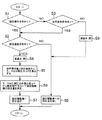
第1実施形態におけるコントローラ28の作用を図2のフローチャートによって説明する。
The operation of the
制御開始後、ステップS1で旋回操作信号があるか(旋回操作されたか)否かが判断され、YESの場合にステップS2で旋回速度信号があるか否か(旋回動作中か)が判断される。 After the start of control, it is determined in step S1 whether there is a turning operation signal (whether turning operation has been performed). If YES, it is determined in step S2 whether there is a turning speed signal (whether turning operation is being performed). .
ステップS1でNO(旋回操作されていない)のときは、ステップS3で旋回速度信号があるか否かが判断され、ここでYESのときは、旋回減速のために旋回リモコン弁12が中立復帰操作されているが上部旋回体2はなお慣性で旋回しているとしてステップS2に移行する。
If NO in step S1 (no turning operation), it is determined in step S3 whether or not there is a turning speed signal. If YES in this case, the turning
ステップS2では旋回速度信号が有るか否かが判断され、YESのときにステップS4で反対側連通弁26または27を開く。
In step S2, it is determined whether or not there is a turning speed signal. If YES, the
続くステップS5〜S7では、旋回操作量と旋回速度から、連通弁26,27が無い(従来回路と同じ)とした場合のモータ出口側圧力ΔPを算出するとともに、この出口側圧力の算出値ΔPからモータ出口側圧力の検出値P1を引いて背圧の低減分を求め、この背圧低減分に相当する回生量(回生トルク)を決定して旋回電動機30に指令する。
In subsequent steps S5 to S7, the motor outlet side pressure ΔP when the
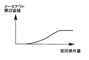
詳述すると、コントローラ28には、図3に示す、旋回操作量とコントロールバルブ13のメータアウト開口面積の関係を表す開口特性が予め記憶され、この開口特性と、検出された旋回操作量からメータアウト開口面積Aを算出する。
More specifically, the
また、検出された旋回速度から油圧モータ11に流れる流量(旋回流量)Qを算出するとともに、この旋回流量Qと、上記算出されたメータアウト開口面積Aを用いて、下記式により出口側圧力ΔPを算出する(ステップS5)。
Further, the flow rate (swing flow rate) Q flowing to the
Q=Cd・A√(2ΔPb/ρ)
Cd:流量係数
ρ :流体密度
そして、出口側圧力の算出値ΔPと検出値P1から、
ΔP−P1
により、連通弁26,27による背圧の低減分を求め、この背圧低減分に相当する回生量を決定し(ステップS6)、ステップS7でこの回生量を旋回電動機30に指令してステップS1に戻る。
Q = Cd · A√ (2ΔPb / ρ)
Cd: Flow coefficient
ρ: fluid density And from the calculated value ΔP of the outlet side pressure and the detected value P1,
ΔP-P1
Thus, a reduction amount of the back pressure by the
なお、ステップS3でNO(旋回操作されていないし旋回速度も出ていない)のときは、旋回停止状態であるとしてステップS8で連通弁26,27を閉じた後、またステップS2でNO(旋回操作されているが旋回速度は出ていない)のときは、押し付け作業等によって実際の旋回動作が行われていないとして直接、それぞれステップS9に移行し、旋回電動機30への回生指令無しとしてステップS1に戻る。
If NO in step S3 (turning operation is not performed and the turning speed is not output), it is determined that the turning is stopped, and the
このこのように、力行時、減速時を問わず、旋回動作中を通じて、連通弁26,27により、モータ吐出油をタンクTに戻すことによって背圧を低減するとともに、旋回電動機30によってこの背圧低減分に相当するだけの回生電力を発生させる構成であるため、旋回力行時のポンプ動力を上げずに回生効率を向上させ、トータルでの省エネ効果を高めることができる。
As described above, the back pressure is reduced by returning the motor discharge oil to the tank T by the
また、旋回動作中は、終始、反対側連通弁26または27を開いた状態とするため、特許文献1記載の公知技術のような切換弁の切換えによる圧力変動がなく、良好な操作性を確保することができる。
Further, since the opposite
また、旋回操作量によって決まるコントロールバルブ13のメータアウト開口面積Aと、旋回速度によって決まるモータ流量Qとから、連通弁26,27が無いものとしたときのモータ出口側圧力ΔPを算出し、この算出値ΔPからモータ出口側圧力の検出値P1を引いて背圧の低減分を求めるため、背圧低減分を正確に割り出し、回生電力の過不足のない適正な回生制御を行うことができる。
Further, from the meter-out opening area A of the
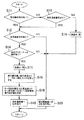
次に、図4によって第2実施形態を説明する。 Next, a second embodiment will be described with reference to FIG.
ショベルにおいては、通常、旋回用油圧モータ11を含めた複数の油圧アクチュエータを一つの油圧ポンプで駆動する構成がとられる。
In general, the excavator is configured to drive a plurality of hydraulic actuators including the turning
この構成において、旋回単独操作時には、元々、旋回力行中のポンプ圧がさほど高くならず、背圧も低い半面、この状態で旋回電動機30に回生作用を行わせるとポンプ圧が上昇するため、全旋回動作を通じたトータルでの省エネ効果が下がる可能性がある。
In this configuration, at the time of the single turning operation, the pump pressure during the turning power running is not so high and the back pressure is low, but if the regenerative action is performed on the turning
一方、複合操作時には、旋回用油圧モータ11以外の油圧アクチュエータの作動圧によってポンプ圧が上昇し、背圧低減のメリットも回生効率の向上効果も大きくなるため、トータルでの省エネ効果が高くなる。
On the other hand, during the combined operation, the pump pressure is increased by the operating pressure of the hydraulic actuator other than the turning
そこで、第2実施形態においては、油圧ポンプ10を旋回用の油圧モータ11を含む複数の油圧アクチュエータで共用する構成をとる場合に、旋回用油圧モータ11のみが作動する旋回単独操作時には上記した回生制御を行わず、旋回用油圧モータ11と他の油圧アクチュエータとが同時に作動する複合操作時のみに上記回生制御を行うように構成されている。
Therefore, in the second embodiment, when the
詳述すると、図4中のステップS11〜S13は図2中(第1実施形態)のステップS1〜S3と同じである。 More specifically, steps S11 to S13 in FIG. 4 are the same as steps S1 to S3 in FIG. 2 (first embodiment).
ステップS14で他のアクチュエータ操作が有る(複合操作)か否かが判断され、YESの場合は、ステップS15〜S18で、図2のステップS4〜S7と同様に連通弁開き、モータ出口側圧力ΔP算出、旋回電動機30の回生量決定、旋回電動機30への回生指令の各処理を行う。
In step S14, it is determined whether or not there is another actuator operation (combined operation). If YES, in steps S15 to S18, the communication valve is opened as in steps S4 to S7 in FIG. Each process of calculation, the regeneration amount determination of the turning
ステップS13でNO(旋回操作も旋回速度も無い)のときは、旋回停止状態であるとしてステップS19で連通弁26,27を閉じた後、またステップS12及びステップS14でNOの場合は直接、それぞれステップS20に移り、旋回電動機30への回生指令無しとしてステップS11に戻る。
If NO in step S13 (no turning operation or turning speed), it is assumed that the turning is stopped, and the
このように、回生制御を旋回単独操作時には行わず、複合操作時のみに行うことで省エネ効果を最大限に高めることができる。 Thus, the energy saving effect can be maximized by performing the regenerative control only during the combined operation, not during the turning single operation.
他の実施形態
(1) 上記実施形態では、連通弁26,27の出口側を通路29を介して油圧ブレーキ装置20の通路23に接続する構成、すなわち、メークアップライン24を、連通弁26,27の出口側をタンクTにつなぐラインとして共用する構成をとったが、連通弁26,27の出口側を専用のタンク接続ラインでタンクTに接続する構成をとってもよい。
Other embodiments
(1) In the embodiment described above, the outlet side of the
(2) 上記実施形態では、モータ両側管路14,15ごとに連通弁26,27を設けたが、両側管路14,15に共用される一つの連通弁を設け、この連通弁を閉じ位置(中立位置)の左右の開き位置との間で切換制御する構成をとってもよい。
(2) In the above embodiment, the
(3) 本発明はショベルに限らず、ショベルを母体として構成される解体機や破砕機等の他の旋回式作業機械にも上記同様に適用することができる。 (3) The present invention is not limited to the excavator, and can be similarly applied to other swivel work machines such as a dismantling machine and a crusher configured with the excavator as a base.
1 下部走行体
2 上部旋回体
11 旋回用油圧モータ
12 旋回操作手段としての旋回リモコン弁
13 コントロールバルブ
14,15 モータ両側管路
26,27 連通弁
28 制御手段としてのコントローラ
30 旋回電動機
31 蓄電器
32,33 旋回操作検出手段としての圧力センサ
34 旋回速度検出手段としての旋回速度センサ
35,36 モータ出口側圧力を検出する圧力センサ
DESCRIPTION OF SYMBOLS 1 Lower traveling body 2
Claims (3)
Priority Applications (5)
| Application Number | Priority Date | Filing Date | Title |
|---|---|---|---|
| JP2011123307A JP5071572B1 (en) | 2011-06-01 | 2011-06-01 | Swivel work machine |
| US14/007,978 US8826656B2 (en) | 2011-05-02 | 2012-04-19 | Slewing type working machine |
| EP12779820.5A EP2706152B1 (en) | 2011-05-02 | 2012-04-19 | Slewing type working machine |
| CN201280021510.6A CN103534419B (en) | 2011-05-02 | 2012-04-19 | Swinging engineering machinery |
| PCT/JP2012/002724 WO2012150653A1 (en) | 2011-05-02 | 2012-04-19 | Rotation-type working machine |
Applications Claiming Priority (1)
| Application Number | Priority Date | Filing Date | Title |
|---|---|---|---|
| JP2011123307A JP5071572B1 (en) | 2011-06-01 | 2011-06-01 | Swivel work machine |
Publications (2)
| Publication Number | Publication Date |
|---|---|
| JP5071572B1 JP5071572B1 (en) | 2012-11-14 |
| JP2012251329A true JP2012251329A (en) | 2012-12-20 |
Family
ID=47277837
Family Applications (1)
| Application Number | Title | Priority Date | Filing Date |
|---|---|---|---|
| JP2011123307A Active JP5071572B1 (en) | 2011-05-02 | 2011-06-01 | Swivel work machine |
Country Status (1)
| Country | Link |
|---|---|
| JP (1) | JP5071572B1 (en) |
Families Citing this family (1)
| Publication number | Priority date | Publication date | Assignee | Title |
|---|---|---|---|---|
| CN108940560B (en) * | 2018-07-16 | 2024-04-02 | 江阴双马重工装备有限公司 | Remote control system of crusher for field unmanned operation |
Citations (4)
| Publication number | Priority date | Publication date | Assignee | Title |
|---|---|---|---|---|
| JPH08200305A (en) * | 1995-01-27 | 1996-08-06 | Hitachi Constr Mach Co Ltd | Hydraulic circuit for driving inertial body |
| JP2005344431A (en) * | 2004-06-04 | 2005-12-15 | Sumitomo (Shi) Construction Machinery Manufacturing Co Ltd | Revolving electric motor equipment |
| JP2010065510A (en) * | 2008-09-12 | 2010-03-25 | Sumitomo (Shi) Construction Machinery Co Ltd | Driving device for working machine |
| JP2012127123A (en) * | 2010-12-15 | 2012-07-05 | Sumitomo Heavy Ind Ltd | Hybrid construction machine |
-
2011
- 2011-06-01 JP JP2011123307A patent/JP5071572B1/en active Active
Patent Citations (4)
| Publication number | Priority date | Publication date | Assignee | Title |
|---|---|---|---|---|
| JPH08200305A (en) * | 1995-01-27 | 1996-08-06 | Hitachi Constr Mach Co Ltd | Hydraulic circuit for driving inertial body |
| JP2005344431A (en) * | 2004-06-04 | 2005-12-15 | Sumitomo (Shi) Construction Machinery Manufacturing Co Ltd | Revolving electric motor equipment |
| JP2010065510A (en) * | 2008-09-12 | 2010-03-25 | Sumitomo (Shi) Construction Machinery Co Ltd | Driving device for working machine |
| JP2012127123A (en) * | 2010-12-15 | 2012-07-05 | Sumitomo Heavy Ind Ltd | Hybrid construction machine |
Also Published As
| Publication number | Publication date |
|---|---|
| JP5071572B1 (en) | 2012-11-14 |
Similar Documents
| Publication | Publication Date | Title |
|---|---|---|
| JP5333511B2 (en) | Swivel work machine | |
| JP5687150B2 (en) | Construction machinery | |
| JP5667830B2 (en) | Construction machine having a rotating body | |
| WO2012150653A1 (en) | Rotation-type working machine | |
| JP5858818B2 (en) | Construction machinery | |
| WO2015122213A1 (en) | Hydraulic drive device for construction machine | |
| WO2010128645A1 (en) | Control device for hybrid construction machine | |
| JP2011220390A (en) | Control device of hydraulic working machine | |
| JPWO2013099710A1 (en) | Power regeneration device for work machine and work machine | |
| US9777463B2 (en) | Construction machine | |
| JP6013503B2 (en) | Construction machinery | |
| JP5992886B2 (en) | Work machine | |
| JP5590074B2 (en) | Swivel work machine | |
| JP5071572B1 (en) | Swivel work machine | |
| JP2016038074A (en) | Control device for turning type work machine | |
| JP5071571B1 (en) | Swivel work machine | |
| JP5864309B2 (en) | Excavator | |
| JP5201239B2 (en) | Swivel work machine | |
| JP5197231B2 (en) | Energy recovery device for work machines | |
| JP5723947B2 (en) | Construction machine having a rotating body |
Legal Events
| Date | Code | Title | Description |
|---|---|---|---|
| TRDD | Decision of grant or rejection written | ||
| A01 | Written decision to grant a patent or to grant a registration (utility model) |
Free format text: JAPANESE INTERMEDIATE CODE: A01 |
|
| A61 | First payment of annual fees (during grant procedure) |
Free format text: JAPANESE INTERMEDIATE CODE: A61 Effective date: 20120806 |
|
| R150 | Certificate of patent or registration of utility model |
Ref document number: 5071572 Country of ref document: JP Free format text: JAPANESE INTERMEDIATE CODE: R150 Free format text: JAPANESE INTERMEDIATE CODE: R150 |
|
| FPAY | Renewal fee payment (event date is renewal date of database) |
Free format text: PAYMENT UNTIL: 20150831 Year of fee payment: 3 |