JP2012249451A - Power conversion apparatus - Google Patents
Power conversion apparatus Download PDFInfo
- Publication number
- JP2012249451A JP2012249451A JP2011120090A JP2011120090A JP2012249451A JP 2012249451 A JP2012249451 A JP 2012249451A JP 2011120090 A JP2011120090 A JP 2011120090A JP 2011120090 A JP2011120090 A JP 2011120090A JP 2012249451 A JP2012249451 A JP 2012249451A
- Authority
- JP
- Japan
- Prior art keywords
- power
- power supply
- inverter unit
- unit
- leakage
- Prior art date
- Legal status (The legal status is an assumption and is not a legal conclusion. Google has not performed a legal analysis and makes no representation as to the accuracy of the status listed.)
- Pending
Links
Images


Landscapes
- Emergency Protection Circuit Devices (AREA)
Abstract
Description
本発明は、発電装置で発電された電力を所望の電力に変換して負荷に供給する電力変換装置に関する。 The present invention relates to a power converter that converts power generated by a power generator into desired power and supplies the power to a load.
従来、太陽電池(発電装置)で発電された直流電力をパワーコンディショナ(電力変換装置)で交流電力に変換した後に負荷に供給する太陽光発電システム(電力供給システム)が提供されている(例えば、特許文献1参照)。 Conventionally, a photovoltaic power generation system (power supply system) that supplies DC power to a load after converting DC power generated by a solar cell (power generation device) into AC power by a power conditioner (power conversion device) is provided (for example, , See Patent Document 1).
特許文献1記載の従来例は、系統連系形の太陽光発電システムであって、そのパワーコンディショナは、系統連系運転と自立運転の2つの運転モードが切り換えられるようになっている。そして、特許文献1記載のパワーコンディショナは、太陽電池の直流出力を交流に変換するインバータを備え、自立運転時には解列開閉器により電力系統から系統分離されるとともに、自立運転用ブレーカを介して自立運転用給電装置(コンセント)に給電する。
The conventional example described in
ところで、自立運転時のパワーコンディショナのように電力系統から独立した電力変換装置においては、漏電や地絡(以下、漏電等と略す。)を検出して給電路を遮断する機能が設けられていなかった。つまり、給電路に発生する漏電等の検出には、通常、零相変流器が用いられるが、漏電等によって給電路に流れる不平衡電流を零相変流器で検出するためには、少なくともインバータの出力側で給電路が接地されていなければならない。しかしながら、上記従来例ではインバータの出力側で給電路が接地されていないために漏電等を検出することができなかった。 By the way, in a power converter independent of the power system, such as a power conditioner during self-sustained operation, a function of detecting a leakage or a ground fault (hereinafter abbreviated as a leakage) is provided. There wasn't. In other words, a zero-phase current transformer is usually used to detect a leakage generated in the power supply path, but at least in order to detect an unbalanced current flowing in the power supply path due to a leakage current or the like with the zero-phase current transformer, at least The feed line must be grounded on the output side of the inverter. However, in the above conventional example, since the power feeding path is not grounded on the output side of the inverter, it is not possible to detect a leakage or the like.
本発明は、上記課題に鑑みて為されたものであり、電力系統から切り離された状態でも漏電や地絡の検出を可能とすることを目的とする。 The present invention has been made in view of the above problems, and an object of the present invention is to make it possible to detect an electric leakage or a ground fault even when disconnected from a power system.
本発明の電力変換装置は、直流電力を交流電力に変換するインバータ部と、当該インバータ部が具備する複数の出力端のうちで電力系統から切り離されている少なくとも何れか1つの出力端を接地する接地回路とを備えることを特徴とする。 The power conversion device of the present invention grounds at least one output terminal disconnected from the power system among the plurality of output terminals provided in the inverter unit and the inverter unit that converts DC power into AC power. And a ground circuit.
この電力変換装置において、前記接地回路は、電流制限素子を介して前記出力端を接地してなることが好ましい。 In this power conversion device, it is preferable that the ground circuit is configured such that the output terminal is grounded via a current limiting element.
この電力変換装置において、前記インバータ部は一対の出力端を具備し、前記接地回路は、当該一対の出力端をそれぞれ電流制限素子を介して各別に接地してなることが好ましい。 In this power conversion device, it is preferable that the inverter unit includes a pair of output terminals, and the grounding circuit grounds the pair of output terminals individually via current limiting elements.
この電力変換装置において、前記インバータ部の出力側若しくは前記接地回路の出力側に設けられて給電路に流れる不平衡電流を検出する電流検出器と、当該電流検出器で検出される不平衡電流が所定のしきい値を超えた場合に前記インバータ部から前記給電路への電力供給を停止させる電力供給停止手段とを備えることが好ましい。 In this power conversion device, a current detector that is provided on the output side of the inverter unit or the output side of the ground circuit and detects an unbalanced current flowing in a power feeding path, and an unbalanced current detected by the current detector It is preferable to include a power supply stop unit that stops power supply from the inverter unit to the power supply path when a predetermined threshold value is exceeded.
この電力変換装置において、前記インバータ部の入力側に設けられた漏電検出部と、当該漏電検出部で漏電が検出された場合に前記インバータ部から前記給電路への電力供給を停止させる電力供給停止手段とを備えることが好ましい。 In this power conversion device, a leakage detection unit provided on the input side of the inverter unit, and a power supply stop that stops power supply from the inverter unit to the power supply path when leakage is detected by the leakage detection unit Means.
この電力変換装置において、前記インバータ部は、入力側と出力側が電気的に絶縁されていない非絶縁型であることが好ましい。 In this power converter, the inverter unit is preferably a non-insulated type in which the input side and the output side are not electrically insulated.
この電力変換装置において、前記インバータ部の出力端を電力系統に接続するための系統連系用の端子部と、前記インバータ部の出力端と前記系統連系用端子部との接続を開閉する開閉部と、前記インバータ部の出力端に対して前記接地回路を介して前記開閉部及び前記系統連系用端子部と並列に接続された自立運転用の端子部とを備えることが好ましい。 In this power conversion device, a terminal unit for grid connection for connecting the output end of the inverter unit to the power system, and an open / close for opening and closing a connection between the output end of the inverter unit and the terminal unit for grid connection And a terminal part for independent operation connected in parallel to the switching part and the grid connection terminal part via the ground circuit with respect to the output end of the inverter part.
この電力変換装置において、前記インバータ部の入力側又は出力側に直流漏電検出器が設けられ、当該直流漏電検出器で検出される漏電電流が所定のしきい値を超えた場合に前記インバータ部から前記給電路への電力供給を停止させる電力供給停止手段とを備えることが好ましい。 In this power conversion device, a DC leakage detector is provided on the input side or output side of the inverter unit, and when the leakage current detected by the DC leakage detector exceeds a predetermined threshold, the inverter unit It is preferable to include a power supply stopping unit that stops power supply to the power supply path.
本発明の電力変換装置は、電力系統から切り離された状態でも漏電や地絡の検出が可能になるという効果がある。 The power converter of the present invention has an effect that it is possible to detect a leakage or a ground fault even in a state where the power converter is disconnected from the power system.
(実施形態1)
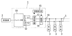
本実施形態の電力変換装置1は、図1に示すように発電装置2で発電される直流電力を交流電力に変換し、給電路5を介して負荷3に交流電力を供給するものである。なお、発電装置2は太陽電池や燃料電池などで構成される。
(Embodiment 1)
As shown in FIG. 1, the
電力変換装置1は、直流電力を交流電力に変換するインバータ部10と、インバータ部10が具備する複数(図示例では2つ)の出力端のうちで電力系統から切り離されている少なくとも何れか1つの出力端を接地する接地回路とを備えている。本実施形態における接地回路は、インバータ部10の一対の出力端をそれぞれ電流制限素子11,12を介して各別に接地している。電流制限素子11,12は、例えば抵抗素子からなり、インバータ部10の出力端間に直列接続されている。そして、電流制限素子11,12の接続点がグランドに接地されている。なお、電力変換装置1の出力端子19と給電路5との間に漏電遮断器4が接続されている。
The
而して、何れかの負荷3若しくは給電路5から負荷3への給電線50で漏電等が発生すると、給電線50と給電路5と接地回路で形成される電流ループに漏洩電流又は地絡電流(以下、漏洩電流等と略す。)が流れる。このとき、接地回路を構成する電流制限素子11(又は12)によって漏洩電流等が制限されるため、感電事故などの発生を回避することができる。さらに、電流ループに流れる漏洩電流等を検出した漏電遮断器4が動作(トリップ)することにより、電流ループが遮断されて漏洩電流等が流れなくなる。
Thus, when a leakage occurs in any of the
上述のように本実施形態の電力変換装置1では、インバータ部10の出力端が接地回路によって接地されているので、電力系統から切り離された状態でも漏電や地絡の検出が可能になる。
As described above, in the
(実施形態2)
本実施形態の電力変換装置1は、給電路5に流れる不平衡電流を検出する電流検出器13と、電流検出器13で検出される不平衡電流が所定のしきい値を超えた場合にインバータ部10から給電路5への電力供給を停止させる電力供給停止手段とを備えている。
(Embodiment 2)
The
電流検出器13は零相変流器からなり、接地回路と出力端子19との間に設けられている。また電力供給停止手段は、電流検出器13と出力端子19との間に設けられた開閉部14と、漏電検出部15とで構成される。開閉部14は、例えば、インバータ部10の出力端と出力端子19との間に挿入された常閉型の電磁リレーからなる。漏電検出部15は、電流検出器13で検出される不平衡電流のレベルを所定のしきい値と比較し、不平衡電流のレベルがしきい値を超えた場合に開閉部14の電磁リレーをオフさせてインバータ部10から給電路5への電力供給を停止させる。なお、このような漏電検出部15は論理回路又はマイクロコンピュータなどで実現可能である。
The
而して、給電線50と給電路5と接地回路で形成される電流ループに漏洩電流等が流れ、電流検出器13で検出される不平衡電流のレベルがしきい値を超えると、漏電検出部15が開閉部14を開成させるので、電流ループが遮断されて漏洩電流等が流れなくなる。
Thus, when a leakage current flows through a current loop formed by the
上述のように本実施形態の電力変換装置1では、電流検出器13と電力供給停止手段(開閉部14及び漏電検出部15)を備えたことにより、漏電遮断器4が無くても漏電や地絡の検出及び給電路5の遮断が可能になる。
As described above, the
ここで、実施形態1,2ではインバータ部10の一対の出力端が双方とも電流制限素子11,12を介して接地されているが、図3(a)に示すように一方の出力端(図示例では上側の出力端)のみが電流制限素子11を介して接地されていても構わない。さらに、図3(b)に示すようにインバータ部10の一方の出力端のみが電流制限素子11を介さずに接地されても構わない。ただし、接地回路が図3に示す構成であれば、インバータ部10の接地されていない側の出力端に接続されている方の給電路5で発生した漏電等しか検出することはできない。なお、図3とは逆にインバータ部10の他方の出力端(下側の出力端)のみが接地されても構わない。
Here, in the first and second embodiments, the pair of output terminals of the
(実施形態3)
本実施形態の電力変換装置1は、図4に示すように系統連系形の太陽光発電システムにおけるパワーコンディショナとして構成されている。ただし、本実施形態の基本構成は実施形態2と共通であるので、共通の構成要素には同一の符号を付して適宜説明を省略する。
(Embodiment 3)
The
本実施形態の電力変換装置1では、インバータ部10の出力端間に開閉部14と解列開閉器16が並列に接続され、開閉部14の出力側に接地回路と電流検出器13が設けられている。解列開閉器16は、インバータ部10の出力端と、系統連系用端子部18との間に設けられており、系統連系用端子部18に接続された電力系統100をインバータ部10から切り離す(解列する)ものである。つまり、電力変換装置1は、通常、電力系統100がインバータ部10の出力端と接続されて系統連系運転を行い、停電等の異常時に解列開閉器16が解列して自立運転を行う。ただし、このように系統連系運転と自立運転が切り換えられる太陽光発電システムについては従来周知であるから、詳細な構成及び動作の説明は省略する。
In the
漏電検出部15は、電流検出器13で検出される不平衡電流のレベルを所定のしきい値と比較することで漏電等を検出する。そして、系統連系運転中に漏電等を検出した場合、漏電検出部15は、解列開閉器16を解列させるとともに開閉部14の開成させて電力系統100並びにインバータ部10から給電路5への電力供給を停止させる。また、自立運転中に漏電等を検出した場合、漏電検出部15は、開閉部14の開成させてインバータ部10から給電路5への電力供給を停止させる。
The
上述のように本実施形態の電力変換装置1では、系統連系形の太陽光発電システムにおけるパワーコンディショナであり、電力系統から切り離された状態(自立運転中)でも漏電や地絡の検出が可能になる。
As described above, the
ここで、インバータ部10の出力端に電流検出器を設け、この電流検出器で検出される不平衡電流がしきい値を超えた場合に漏電検出部15が解列開閉器16を解列させたり、開閉部14を開成させてもよい。また、インバータ部10が入力側と出力側が絶縁されていない非絶縁型である場合、インバータ部10の入力端に電流検出器を設けても構わない。さらに、実施形態1と同様に電力変換装置1の出力端子19(自立運転用の端子部)と給電路5の間に漏電遮断器4が挿入されてもよい。
Here, a current detector is provided at the output terminal of the
あるいは、インバータ部10の入力側又は出力側の何れか一方に直流漏電検出器が設けられ、この直流漏電検出器で検出される漏電電流がしきい値を超えた場合に漏電検出部15が解列開閉器16を解列させたり、開閉部14を開成させてもよい。このようにすれば、電力変換装置1の自立運転中に漏電等が生じた場合に負荷3への電力供給を停止することができる。なお、上述のような直流漏電検出器は従来周知であるから詳細な構成の図示及び説明は省略する。
Alternatively, a DC leakage detector is provided on either the input side or the output side of the
1 電力変換装置
10 インバータ部
11,12 電流制限素子(接地回路)
1 Power converter
10 Inverter section
11, 12 Current limiting element (grounding circuit)
Claims (8)
Priority Applications (1)
| Application Number | Priority Date | Filing Date | Title |
|---|---|---|---|
| JP2011120090A JP2012249451A (en) | 2011-05-30 | 2011-05-30 | Power conversion apparatus |
Applications Claiming Priority (1)
| Application Number | Priority Date | Filing Date | Title |
|---|---|---|---|
| JP2011120090A JP2012249451A (en) | 2011-05-30 | 2011-05-30 | Power conversion apparatus |
Publications (1)
| Publication Number | Publication Date |
|---|---|
| JP2012249451A true JP2012249451A (en) | 2012-12-13 |
Family
ID=47469353
Family Applications (1)
| Application Number | Title | Priority Date | Filing Date |
|---|---|---|---|
| JP2011120090A Pending JP2012249451A (en) | 2011-05-30 | 2011-05-30 | Power conversion apparatus |
Country Status (1)
| Country | Link |
|---|---|
| JP (1) | JP2012249451A (en) |
Citations (4)
| Publication number | Priority date | Publication date | Assignee | Title |
|---|---|---|---|---|
| JP2000217397A (en) * | 1999-01-22 | 2000-08-04 | Honda Motor Co Ltd | Generator |
| JP2001169561A (en) * | 1999-12-02 | 2001-06-22 | Canon Inc | Power supply device, controller and its control method |
| JP2003087978A (en) * | 2001-09-07 | 2003-03-20 | Toshiba Corp | Generating unit, panel board and power supply system using the same |
| CA2399747A1 (en) * | 2001-09-28 | 2003-03-28 | Himamshu V. Prasad | Ballast with protection circuit for preventing inverter startup during an output ground-fault condition |
-
2011
- 2011-05-30 JP JP2011120090A patent/JP2012249451A/en active Pending
Patent Citations (4)
| Publication number | Priority date | Publication date | Assignee | Title |
|---|---|---|---|---|
| JP2000217397A (en) * | 1999-01-22 | 2000-08-04 | Honda Motor Co Ltd | Generator |
| JP2001169561A (en) * | 1999-12-02 | 2001-06-22 | Canon Inc | Power supply device, controller and its control method |
| JP2003087978A (en) * | 2001-09-07 | 2003-03-20 | Toshiba Corp | Generating unit, panel board and power supply system using the same |
| CA2399747A1 (en) * | 2001-09-28 | 2003-03-28 | Himamshu V. Prasad | Ballast with protection circuit for preventing inverter startup during an output ground-fault condition |
Similar Documents
| Publication | Publication Date | Title |
|---|---|---|
| CA2883094C (en) | Battery energy storage system with arc flash protection, energy conversion system and protection method | |
| US10734944B2 (en) | Inverter having grid disconnection point and insulation resistance measurement and method for measuring an insulation resistance | |
| JP5542942B2 (en) | Grounding device | |
| US9806516B2 (en) | Method and device for protecting several strings of a photovoltaic generator from reverse currents | |
| US20130222951A1 (en) | Fault protection circuit for photovoltaic power system | |
| WO2012046331A1 (en) | Failure detecting apparatus | |
| US9214817B2 (en) | Circuitry arrangement for a solar power plant comprising a DC voltage source for an offset voltage | |
| CN102959818A (en) | An hvdc switchyard and an hvdc switchyard system | |
| US9509231B2 (en) | Power converter system, damping system, and method of operating a power converter system | |
| JP2013501495A (en) | Reverse current sensor | |
| JP5743913B2 (en) | Power converter | |
| JP2017135889A (en) | Power conversion device, and power conversion system | |
| JP6180049B2 (en) | Standby power system and method of disconnecting the regional distribution network from the upper transmission network | |
| CN204045601U (en) | Inverter | |
| JP6231900B2 (en) | Photovoltaic power generation facility for grid connection | |
| US20220231513A1 (en) | Method for operating an energy generating system, and energy generating system comprising said method | |
| JP2012249451A (en) | Power conversion apparatus | |
| JP4750071B2 (en) | Loop power distribution system | |
| JP6229971B2 (en) | Power supply device | |
| AU2015285887B2 (en) | Residual current protection device and residual current protection system | |
| US20230291303A1 (en) | Power converter for transferring power between an ac side and a dc side, and power supply method | |
| JP2013229960A (en) | Power converter | |
| JPH0150168B2 (en) | ||
| CN201975772U (en) | Conductive alternating-current fault current limiter | |
| JP2005094897A (en) | Single operation prevention device |
Legal Events
| Date | Code | Title | Description |
|---|---|---|---|
| A621 | Written request for application examination |
Free format text: JAPANESE INTERMEDIATE CODE: A621 Effective date: 20140210 |
|
| A711 | Notification of change in applicant |
Free format text: JAPANESE INTERMEDIATE CODE: A711 Effective date: 20141008 |
|
| A977 | Report on retrieval |
Free format text: JAPANESE INTERMEDIATE CODE: A971007 Effective date: 20141010 |
|
| A131 | Notification of reasons for refusal |
Free format text: JAPANESE INTERMEDIATE CODE: A131 Effective date: 20141104 |
|
| A521 | Written amendment |
Free format text: JAPANESE INTERMEDIATE CODE: A523 Effective date: 20141224 |
|
| A131 | Notification of reasons for refusal |
Free format text: JAPANESE INTERMEDIATE CODE: A131 Effective date: 20150526 |
|
| A02 | Decision of refusal |
Free format text: JAPANESE INTERMEDIATE CODE: A02 Effective date: 20151117 |