JP2012249166A - Communication system - Google Patents
Communication system Download PDFInfo
- Publication number
- JP2012249166A JP2012249166A JP2011120598A JP2011120598A JP2012249166A JP 2012249166 A JP2012249166 A JP 2012249166A JP 2011120598 A JP2011120598 A JP 2011120598A JP 2011120598 A JP2011120598 A JP 2011120598A JP 2012249166 A JP2012249166 A JP 2012249166A
- Authority
- JP
- Japan
- Prior art keywords
- communication
- node
- communication request
- broadcast
- request
- Prior art date
- Legal status (The legal status is an assumption and is not a legal conclusion. Google has not performed a legal analysis and makes no representation as to the accuracy of the status listed.)
- Granted
Links
- 238000004891 communication Methods 0.000 title claims abstract description 551
- 230000005540 biological transmission Effects 0.000 claims abstract description 75
- 238000001514 detection method Methods 0.000 claims description 14
- 238000000034 method Methods 0.000 description 11
- 230000006870 function Effects 0.000 description 6
- 235000008694 Humulus lupulus Nutrition 0.000 description 5
- 238000010586 diagram Methods 0.000 description 3
- 238000009434 installation Methods 0.000 description 3
- 238000012986 modification Methods 0.000 description 1
- 230000004048 modification Effects 0.000 description 1
- 230000004044 response Effects 0.000 description 1
Images


Abstract
Description
本発明は、通信システムに係り、特に、データの無線受信を行う受信手段と、データの無線送信を行う送信手段と、を備えた通信ノードを複数有して無線メッシュネットワークを構成する通信システムに関するものである。 The present invention relates to a communication system, and more particularly, to a communication system having a plurality of communication nodes each including a reception unit that wirelessly receives data and a transmission unit that wirelessly transmits data to form a wireless mesh network. Is.
全ての通信ノードが中継局となれるメッシュネットワークにおいては、送信元の通信ノードから送信先の通信ノードまでの経路を選択する必要がある。通信ノードの設置位置が固定である場合、一般的には複数の通信ノードの設置位置の関係から上記経路を選択することが行われている。 In a mesh network in which all communication nodes can be relay stations, it is necessary to select a route from a transmission source communication node to a transmission destination communication node. When the installation position of the communication node is fixed, generally, the route is selected based on the relationship between the installation positions of a plurality of communication nodes.
ここで、通信ノード間に障害物が存在したり、有線の配索が困難な場所では、通信ノードとして無線端末を利用する。このように設置位置が固定されている通信ノードであっても無線端末を利用した場合、例えば以下の例1、例2ような諸々の影響により、経路の状態が変わるため通信ノードの設置位置の関係だけでは、最適な経路を選択できない、という問題点があった。 Here, a wireless terminal is used as a communication node in a place where an obstacle exists between the communication nodes or a wired connection is difficult. Even when the communication node has a fixed installation position as described above, when a wireless terminal is used, the path state changes due to various influences such as the following Example 1 and Example 2. There was a problem that the optimum route could not be selected only by the relationship.
例1:近隣で利用されている無線器の送信電波によって、通信ノード間の電波環境に影響を及ぼす。例2通信ノード間の途中に人など、移動体が入ることによって電波環境が悪化する。 Example 1: The radio wave environment between communication nodes is affected by the radio wave transmitted from a wireless device used in the vicinity. Example 2 The radio wave environment deteriorates when a moving object such as a person enters the middle between communication nodes.
そこで、このような問題点を解決するために、通信の直前に送信先の通信ノードから他の通信ノードに対して送信要求をブロードキャスト送信し、この送信要求に応じて他の通信ノードから送信され、送信先の通信ノードが受け取った電波の受信強度が閾値以上の経路の中から選択する通信システムが提案されている(例えば非特許文献1)。 Therefore, in order to solve such a problem, a transmission request is broadcast from another communication node to another communication node immediately before communication, and transmitted from another communication node in response to this transmission request. There has been proposed a communication system that selects a path from which a reception intensity of a radio wave received by a destination communication node is greater than or equal to a threshold (for example, Non-Patent Document 1).
しかしながら、上述した通信システムでは、送信先の通信ノードからの送信要求を受け取った他の通信ノードの全てが電波を送信するために経路を決定するための通信量が多くなってしまう、という問題があった。特に他の通信ノードから送信先の通信ノードへ送信される閾値以下の電波の送信は無駄である。 However, in the above-described communication system, there is a problem in that the amount of communication for determining a route for all of the other communication nodes that have received a transmission request from the destination communication node increases in order to transmit radio waves. there were. In particular, transmission of radio waves below a threshold value transmitted from another communication node to a destination communication node is useless.
そこで、本発明は、経路を決定するための通信量を抑えることができる通信システムを提供することを課題とする。 Accordingly, an object of the present invention is to provide a communication system that can suppress the amount of communication for determining a route.
上述した課題を解決するための請求項1記載の発明は、データの無線受信を行う受信手段と、データの無線送信を行う送信手段と、を備えた通信ノードを複数有して無線メッシュネットワークを構成する通信システムにおいて、前記複数の通信ノードの各々が、データの通信要求が発生すると、通信要求を前記送信手段から他の通信ノードに対してブロードキャスト送信させる通信要求手段と、前記受信手段が受信した通信要求の受信強度を検出する第1受信強度検出手段と、前記検出された通信要求の受信強度が第1通信閾値以上のときに送信元を付加した通信可能通知を前記送信手段から送信させる通信可能通知手段と、前記通信要求を送信した後に前記受信手段が受信した前記通信可能通知に付加された送信元に通信要求先がある場合、通信要求先との直接通信を行い、通信要求先がない場合、前記通信可能通知に付加された送信元の中から1つを中継局として選択し、前記通信要求先とのホッピング通信を行う通信手段と、を備えたことを特徴とする通信システムに存する。
The invention according to
請求項2記載の発明は、前記通信要求手段が、前記通信要求に通信要求先を付加して送信させ、前記複数の通信ノードの各々が、前記受信手段が受信した通信要求に付加された通信要求先が自ノードであるか否かを判定する通信要求先判定手段と、前記通信要求先判定手段により自ノードでないと判定された場合、自ノードが通信要求先に対する中継局となれるか否かを判定する中継局判定手段と、前記検出された通信要求の受信強度が第1通信閾値以上であっても、前記通信要求先判定手段により自ノードでないと判定され、かつ、前記中継局判定手段により中継局にもなれないと判定された場合は、前記通信可能通知手段による前記通信可能通知の送信を停止する通知停止手段と、をさらに備えたことを特徴とする請求項1に記載の通信システムに存する。
According to a second aspect of the present invention, the communication request unit adds a communication request destination to the communication request and transmits the communication request, and each of the plurality of communication nodes adds the communication request received by the receiving unit. A communication request destination determination unit that determines whether or not the request destination is the local node, and whether or not the local node can be a relay station for the communication request destination when the communication request destination determination unit determines that the request destination is not the local node. A relay station determining means for determining whether the detected node is not a local node by the communication request destination determining means even if the detected reception intensity of the communication request is equal to or higher than a first communication threshold, and the relay station determining means 2. The communication according to
請求項3記載の発明は、前記通信要求手段が、前記通信要求に前記第1通信閾値をさらに付加して送信し、前記通信可能通知手段が、前記検出された通信要求の受信強度と当該通信要求に付加された前記第1通信閾値とを比較することを特徴とする請求項1又は2に記載の通信システムに存する。
According to a third aspect of the present invention, the communication request unit further transmits the communication request with the first communication threshold added thereto, and the communication enable notification unit transmits the detected communication request reception strength and the communication. The communication system according to
請求項4記載の発明は、前記受信手段が受信した通信可能通知の受信強度を検出する第2受信強度検出手段をさらに備え、前記通信手段が、前記通信可能通知の送信元の中に通信要求先があっても前記第2受信強度検出手段により検出された受信強度が第2通信閾値未満の場合、通信要求先がないと判定することを特徴とする請求項1〜3何れか1項に記載の通信システムに存する。
The invention according to
以上説明したように請求項1記載の発明によれば、通信要求を受け取った全ての通信ノードから通信可能通知が送信されることなく、通信要求を受け取った通信ノードのうち通信要求の受信強度が第1通信閾値以上の通信ノードからしか通信可能通知が送信されないので、無駄な通信可能通知の送信が行われること無く、経路を決定するための通信量を抑えることができる。 As described above, according to the first aspect of the present invention, the communication request notification is not transmitted from all the communication nodes that have received the communication request, and the reception strength of the communication request among the communication nodes that have received the communication request is Since the communicable notification is transmitted only from the communication nodes that are equal to or higher than the first communication threshold, it is possible to suppress the amount of communication for determining the route without performing useless communication feasible notification transmission.
請求項2記載の発明によれば、通信要求先でも、通信要求先の中継局にもなれない通信ノードから通信可能通知が送信されることがないので、より一層、無駄な通信可能通知の送信が行われること無く、経路を決定するための通信量を抑えることができる。 According to the second aspect of the present invention, since a communication enable notification is not transmitted from a communication node that cannot be a communication request destination or a communication request destination relay station, a further useless communication enable notification is transmitted. The amount of communication for determining the route can be suppressed without being performed.
請求項3記載の発明によれば、通信要求手段が、通信要求に第1通信閾値をさらに付加して送信し、通信手段が、検出された通信要求の受信強度と当該通信要求に付加された第1通信閾値とを比較するので、各通信ノードに対する第1通信閾値を格納するメモリを必要としないため、コストダウンを図ることができる。
According to the invention described in
請求項4記載の発明によれば、通信手段が、通信可能通知の送信元の中に通信要求先があっても第2受信強度検出手段により検出された通信可能通知の受信強度が第2通信閾値未満の場合、通信要求先がないと判定するので、常に良好な通信環境での通信が行える。 According to the fourth aspect of the present invention, even if the communication means has a communication request destination in the communication possible notification transmission source, the communication strength notification received intensity detected by the second reception intensity detecting means is the second communication. If it is less than the threshold value, it is determined that there is no communication request destination, so communication can always be performed in a good communication environment.
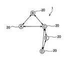
以下、本発明の通信システムを図1乃至図8を参照して説明する。本発明の通信システム1は、図1に示すように、複数の通信ノード20(ノードA、ノードB、ノードC、ノードD、ノードE)を有して構成され、これらのノードA〜Eは無線メッシュネットワークを構成している。
The communication system of the present invention will be described below with reference to FIGS. As shown in FIG. 1, the
図1に示した通信システム1は、ノードAはノードB、Cと相互に無線通信可能に配置されている。ノードBはノードA、Cと相互に無線通信可能に配置されている。ノードCはノードA、B、D、Eと相互に無線通信可能に配置されている。ノードDは、ノードC、Eと相互に無線通信可能に配置されている。ノードEは、ノードC、Dと無線通信可能に配置されている。
In the
次に、上記通信ノード20の構成について図2を参照して以下説明する。同図に示すように、通信ノード20は、アンテナATと、データの無線受信を行うための受信手段としての受信器21と、データの無線送信を行うための送信手段としての送信器22と、第1受信強度検出手段、第2受信強度検出手段としての受信強度検出回路23と、ルーティングテーブル24と、通信テーブル25と、通信ノード20全体の制御を司るCPU26と、を備えている。
Next, the configuration of the
上記受信器21は、アンテナATが受信した他の通信ノード20からのデータを復調してCPU26に対して供給する。上記送信器22は、CPU26から出力されたデータを変調してアンテナATから無線送信させる。上記受信強度検出回路23は、アンテナATが受信したデータの受信強度を検出してCPU26に対して供給する。
The
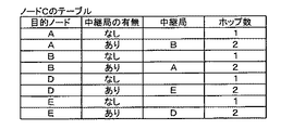
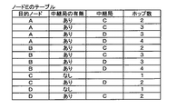
上記ルーティングテーブル24には、図3〜図7に示すように、通信システム1を構成する自身以外の通信ノード20へのホップ数や、中継局の有無、中継局がある場合は中継局名(アドレスなど中継局を示すことができる情報)が通信ノード20毎にテーブル上に予め格納されている。
In the routing table 24, as shown in FIGS. 3 to 7, the number of hops to a
CPU26は、受信データ判別部26aと、API26bと、通信要求ブロードキャスト作成部26cと、通信可否判定部26dと、通信可能通知ブロードキャスト作成部26eと、ブロードキャスト送信タイミング調整部26fと、通信テーブル作成部26gと、通信相手判定部26hと、を備えている。
The
上記受信データ判別部26aは、受信器21が受信したデータの種別が、後述する通信要求ブロードキャスト(=通信要求)か、通信可能通知ブロードキャスト(=通信可能通知)か、受信通信フレームかを判別する。
The received
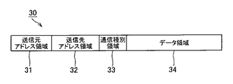
上記API26bは、アプリケーションから通信要求が発生すると、送信通信フレームを作成して後述する通信相手判定部26hに対して出力する。この送信通信フレームの構成例について図8を参照して説明する。図8は、通信ノード20間で送受信されるデータのフレーム構成例を示す図である。同図に示すように、通信ノード20間で送受信されるデータ30は、送信元アドレス領域31と、送信先アドレス領域32と、通信種別領域33と、データ領域34と、から構成されている。
When a communication request is generated from an application, the
上記API26bは、送信元アドレス領域31に自ノードのアドレスを格納し、通信種別領域33に通信フレームである旨を示す情報を格納し、データ領域34に送信要求先(以下目的ノード)のアドレスと目的ノードへ送信したい通信データを格納した送信通信フレームを作成する。なお、送信先は後述する通信相手判定部26hが決定するため、API26bは送信先アドレス領域32をブランクにした通信フレームを作成する。
The
また、API26bは、アプリケーションから通信要求が発生すると、目的ノードアドレス及び第1通信閾値を通信要求ブロードキャスト作成部26cに出力する。通信要求ブロードキャスト作成部26cは、API26bから目的ノードアドレス及び第1通信閾値が出力されると、通信要求ブロードキャストを作成して送信器22から送信させる。
Further, when a communication request is generated from the application, the
この通信要求ブロードキャストの構成例について図8を参照して説明する。上記通信要求ブロードキャスト作成部26cは、送信元アドレス領域31に自ノードのアドレスを格納し、送信先アドレス領域32に通信システム1を構成する全ての通信ノード20に送信するためのアドレスであるブロードキャストアドレスを格納し、通信種別領域33に通信要求ブロードキャストである旨を示す情報を格納する。また、通信要求ブロードキャスト作成部26cは、データ領域34にAPI26bから出力された目的ノードアドレス及び第1通信閾値を格納する。
A configuration example of this communication request broadcast will be described with reference to FIG. The communication request
上記通信可否判定部26dは、受信データ判別部26aにより通信要求ブロードキャストが受信されたと判別されたとき、受信強度検出回路23により検出された受信強度を通信要求ブロードキャストの受信強度として取り込む。次に、通信可否判別部26dは、検出された通信要求ブロードキャストの受信強度と通信ブロードキャストのデータ領域34に格納された第1通信閾値とを比較し、その結果、検出された通信要求ブロードキャストの受信強度が第1通信閾値以上のときに通信可能通知ブロードキャスト作成部26eに対して通信可能通知ブロードキャストを作成させる。
When the reception
また、通信可否判別部26dは、受信器21が受信した通信要求ブロードキャストのデータ領域34に格納された目的ノードが自ノードであるか否かを判別し、自ノードでないと判定された場合、自ノードが目的ノードに対する中継局となれるか否かをルーティングテーブル24を参照して判定する。
Further, the communication
ここで、例えば、自ノードがノードA、受信した通信要求ブロードキャストの送信元がノードC(即ち、通信要求ブロードキャストの送信元アドレス領域31にノードCのアドレスが格納されている)、目的ノードがノードD(即ち、通信要求ブロードキャストのデータ領域34にノードDのアドレスが格納されている)場合について考えてみる。まず、通信可否判別部26dは、自ノード(ノードA)のルーティングテーブル24(図3)を参照して、目的ノードDに対する中継局を検索する。
Here, for example, the own node is node A, the source of the received communication request broadcast is node C (that is, the address of node C is stored in the
ここでは、ノードB、Cが検索される。中継局として検索されたノードCは送信元であるので、通信可否判別部26dは、中継局として検索されたノードBのルーティングテーブル24(図4)を参照して、目的ノードDに対する中継局を検索する。ここでは、ノードA、Cが検索される。ここで検索されたノードAは自ノードであり、ノードCは送信元であるので、通信可否判別部26dは、自ノードAが目的ノードDに対する中継局となれないと判別する。
Here, nodes B and C are searched. Since the node C searched as the relay station is the transmission source, the communication
そして、通信可否判別部26dは、通信要求ブロードキャストの受信強度が第1通信閾値以上であっても、目的ノードが自ノードでもなく、かつ、中継局にもなれない場合は、通信可能通知ブロードキャスト作成部26eに対して通信可能通知ブロードキャストの作成を停止させる。上記通信可能通知ブロードキャスト作成部26eは、通信可否判定部26dからの指示により、通信可能通知ブロードキャストを作成する。
Then, if the communication request broadcast reception strength is equal to or higher than the first communication threshold, the communication
この通信可能通知ブロードキャストの構成例について図8を参照して説明する。通信可能通知ブロードキャスト作成部26eは、送信元アドレス領域31に自ノードのアドレスを格納し、送信先アドレス領域32に通信システム1を構成する全ての通信ノード20に送信するためのアドレスであるブロードキャストアドレスを格納し、通信種別領域33に通信可能通知ブロードキャストである旨を示す情報を格納する。また、通信可能通知ブロードキャスト作成部26eは、データ領域34に通信要求ブロードキャストに格納された目的ノードアドレスを格納する。
A configuration example of the communication enable notification broadcast will be described with reference to FIG. The communicable notification
上記ブロードキャスト送信タイミング調整部26fは、通信要求ブロードキャストを受信したタイミングを起点として、自ノードがブロードキャストで通信を行えるタイミングをカウントし、そのカウントしたタイミングで作成した通信可能通知ブロードキャストを送信器22から送信させる。
The broadcast transmission
通信テーブル作成部26gは、通信可能通知ブロードキャストを受信すると、そのとき受信強度検出回路23から検出された受信強度を通信可能通知ブロードキャストの受信強度として取り込む。そして、通信テーブル作成部26gは、受信した通信可能通知ブロードキャストの送信元と受信強度との関係を示す通信テーブル25を作成する。
When the communication
通信相手判定部26hは、通信要求ブロードキャストを送信した後に通信可能通知ブロードキャストを受信すると、その通信可能通知ブロードキャストの送信元アドレス領域31の中に目的ノードアドレスが格納されている場合、API26bから出力された送信通信フレームの送信先アドレス領域32に目的ノードアドレスを格納して送信させることにより、目的ノードとの直接通信を行う。一方、通信相手判定部26hは、通信可能通知ブロードキャストの送信元アドレス領域31の中に目的ノードアドレスがない場合、通信可能通知ブロードキャストに付加された送信元の中から1つを中継局として選択し、API26bから出力された通信フレームの送信先アドレス領域32に中継局のアドレスを格納して送信させることにより、目的ノードとのホッピング通信を行う。
When the communication
また、上記API26bは、受信通信フレームの送信先が自ノードであり、データ領域34に格納された目的ノードも自ノードである場合は、データ領域34に格納された通信データをアプリケーションに取り込む。上記API26bは、受信通信フレームの送信先が自ノードであり、データ領域34に格納された目的ノードが自ノードでない場合は、受信通信フレームの送信先をブランクにしたものを送信通信フレームとして通信相手判定部26hに対して出力すると共に受信通信フレームに格納された目的ノード及び第1通信閾値を通信要求ブロードキャスト作成部26cに出力する。
In addition, when the destination of the received communication frame is the own node and the target node stored in the
次に、上述した構成の通信システム1のより詳細な動作について図9及び図10に示すフローチャートを参照して説明する。まず、CPU26は、アプリケーションからの通信要求が発生したり、送信先が自ノードであり、目的ノードが自ノードでない受信通信フレームを受信すると、通信要求処理を開始する。
Next, a more detailed operation of the
通信要求処理において、CPU26は、通信要求手段として働き、目的ノード及び第1通信閾値を付加した通信要求ブロードキャストを作成し(ステップS1)、作成した通信要求ブロードキャストを送信する(ステップS2)。その後、CPU26は、他ノードからの通信可能通知ブロードキャストを順次受信すると共に、通信可能通知ブロードキャストの送信元とその受信強度とを対応付けて保存する(ステップS3)。
In the communication request process, the
次に、CPU26は、受信した通信可能通知ブロードキャストの送信元の中に目的ノードがあるか否かを判定する(ステップS4)。目的ノードがあると判定すると(ステップS4でY)、CPU26は、目的ノードからの通信可能通知ブロードキャストの受信強度が第2通信閾値以上であるか否かを判定する(ステップS5)。目的モードからの通信可能通知ブロードキャストの受信強度が第2通信閾値以上であり(ステップS5でY)、安定して通信を行えると判定すると、CPU26は、直接通信を行って(ステップS6)、処理を終了する。
Next, the
一方、受信した通信可能通知ブロードキャストの送信元の中に目的ノードがないと判定すると(ステップS4でN)、CPU26は、通信可能通知ブロードキャストの送信元の中から1つを中継局として選択し(ステップS7)、ホッピング通信を行って(ステップS8)、処理を終了する。中継局としては、例えば、各送信元からの通信可能通知ブロードキャストの受信強度を比較し、さらに各通信ノード20の配置やルーティングテーブル24のホップ数から最も安定して通信できるものが選択される。具体的には、通信可能通知ブロードキャストの受信強度が第2通信閾値以上の送信元であり、かつ、目的ノードまでの距離やホップ数が少ないものが中継局として選択される。以上のことから明らかなように、ステップS4〜S8においてCPU26は請求項中の通信手段として働く。
On the other hand, if it is determined that there is no target node in the transmission source of the received communication notification broadcast (N in step S4), the
一方、CPU26は、受信待ち状態のときに他通信ノード20から通信要求ブロードキャストを受信すると通信可能通知処理を開始する。図10に示すように、通信可能通知処理において、CPU26は、まず、受信した通信要求ブロードキャストの受信強度がその通信要求ブロードキャストに格納された第1通信閾値以上であるか否かを判定する(ステップS11)。
On the other hand, when the
第1通信閾値未満であると(ステップS11でN)、CPU26は、通信要求ブロードキャストを無視して受信待ち状態に戻る。これに対して、第1通信閾値以上であると判定すると(ステップS11でY)、CPU26は、通信要求先判定手段として働き、通信要求ブロードキャストに格納された目的ノードが自ノードであるか否かを判定する(ステップS12)。自ノードである場合(ステップS12でY)、CPU26は、通信可能通知ブロードキャストを作成する(ステップS13)。
If it is less than the first communication threshold (N in step S11), the
一方、CPU26は、通信要求ブロードキャストに格納された目的ノードが自ノードでないと判定すると(ステップS12でN)、CPU26は、中継局判定手段として働き、ルーティングテーブル24を確認して(ステップS14)、自ノードが目的ノードに対する中継局になれるか否かを判定する(ステップS15)。中継局になれないと判定すると(ステップS15でN)、CPU26は、通知停止手段として働き、通信要求ブロードキャストを無視して受信待ち状態に戻る。
On the other hand, when the
これに対して、中継局になれると判定すると(ステップS15でY)、CPU26は、ステップS13に進んで通信可能通知ブロードキャストを作成する。通信可能通知ブロードキャストを作成した後、CPU26は、通信可能通知手段として働き、自ノードの送信タイミングになるまで待った後(ステップS16)、作成した通信可能通知ブロードキャストを送信し(ステップS17)、再び受信待ち状態に戻る。
On the other hand, if it is determined that it can become a relay station (Y in step S15), the
次に、具体的な動作例を図11を参照して説明する。以下に示す動作例では各通信ノード20の受信能力を−65dBm、第1通信閾値を−55dBmとする。
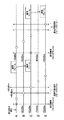
例1:ノードAからノードCへの通信要求が発生した場合(直接通信)について図12を参照して説明する。
Next, a specific operation example will be described with reference to FIG. In the operation example shown below, it is assumed that the reception capability of each
Example 1: A case where a communication request from node A to node C occurs (direct communication) will be described with reference to FIG.
まず、ノードAでノードCとの通信要求が発生する。ノードAから目的ノードアドレスとしてノードCのアドレスが格納され、第1通信閾値として−55dBmが格納された通信要求ブロードキャストが送信される。図11に示すようにノードAからの通信要求ブロードキャストは、ノードB、C、Eで受信される。ノードDは、ノードAからの通信要求ブロードキャストは受信できない。 First, a communication request with node C is generated at node A. A communication request broadcast in which the address of the node C is stored as the target node address and -55 dBm is stored as the first communication threshold is transmitted from the node A. As shown in FIG. 11, the communication request broadcast from the node A is received by the nodes B, C, and E. Node D cannot receive the communication request broadcast from node A.
ノードBでは、通信要求ブロードキャストを受信強度−40dBmで受信している。ノードBでは、通信要求ブロードキャストに含まれる第1通信閾値−55dBmを確認し、通信要求ブロードキャストの受信強度−40dBmが第1通信閾値−55dBm以上であることを確認する。その後、ノードBは、目的ノード(ノードC)が自ノードではないが、ルーティングテーブル24からノードCへの中継局になれることが分かるため、通信可能通知ブロードキャストを作成する。 Node B receives the communication request broadcast at a reception strength of −40 dBm. In the node B, the first communication threshold −55 dBm included in the communication request broadcast is confirmed, and it is confirmed that the reception intensity −40 dBm of the communication request broadcast is equal to or higher than the first communication threshold −55 dBm. After that, since the node B knows that the target node (node C) is not its own node but can become a relay station from the routing table 24 to the node C, the node B creates a communication enable notification broadcast.
ノードCでは、通信要求ブロードキャストを受信強度−50dBmで受信している。ノードCでは、通信要求ブロードキャストに含まれる第1通信閾値−55dBmを確認し、通信要求ブロードキャストの受信強度−50dBmが第1通信閾値−55dBm以上であることを確認する。その後、ノードCは、目的ノードが自ノードであるため、通信可能通知ブロードキャストを作成する。 Node C receives a communication request broadcast at a reception strength of −50 dBm. In node C, the first communication threshold value −55 dBm included in the communication request broadcast is confirmed, and it is confirmed that the reception intensity −50 dBm of the communication request broadcast is equal to or higher than the first communication threshold value −55 dBm. Thereafter, since the target node is its own node, the node C creates a communication enable notification broadcast.
ノードEでは、通信要求ブロードキャストを受信強度−60dBmで受信している。ノードEでは、通信要求ブロードキャストに含まれる第1通信閾値−55dBmを確認し、通信要求ブロードキャストの受信強度−60dBmが第1通信閾値−55dBm未満であることを確認する。その後、ノードEは、通信要求ブロードキャストを受信しなかったものとし通信可能通知ブロードキャストの作成は行わない。 The node E receives the communication request broadcast at a reception strength of −60 dBm. The node E confirms the first communication threshold value −55 dBm included in the communication request broadcast, and confirms that the communication request broadcast reception strength −60 dBm is less than the first communication threshold value −55 dBm. Thereafter, the node E does not receive the communication request broadcast, and does not create a communication enable notification broadcast.
ここで、ノードB、Cは、ノードAからの通信要求ブロードキャストの受信を起点として、通信可能通知ブロードキャストを送信するタイミングをそれぞれ独自に作成する。通信可能通知ブロードキャストの送信タイミングは予め決められた順となる。この通信システム1においては、図12に示すようにノードA、B、C、D、Eの順とする。
Here, the nodes B and C each independently create the timing for transmitting the communication enable notification broadcast from the reception of the communication request broadcast from the node A. The transmission timing of the communication enable notification broadcast is in a predetermined order. In this
図12に示すように、ノードAで通信可能通知ブロードキャストを送信するタイミングでは、ノードAは通信要求ブロードキャストの送信元であるため、何もしない。次に、ノードBのタイミングとなり、ノードBは、上記のように準備された通信可能通知ブロードキャストを送信する。このとき、ノードAでは、ノードBからの通信可能通知ブロードキャストを受信したら、受信の際の受信強度と送信元であるノードBとを対応付けた通信テーブル25を作成する。 As shown in FIG. 12, at the timing of transmitting a communication enable notification broadcast at node A, since node A is the transmission source of the communication request broadcast, nothing is done. Next, at the timing of the node B, the node B transmits the communication enable notification broadcast prepared as described above. At this time, when receiving a communication possible notification broadcast from the node B, the node A creates a communication table 25 in which the reception intensity at the time of reception is associated with the node B that is the transmission source.
次に、ノードCのタイミングとなり、ノードCは、上記のように準備された通信可能通知ブロードキャストを送信する。このとき、ノードAでは、ノードCからの通信可能通知ブロードキャストを受信したら、受信の際の受信強度と送信元であるノードCとを対応付けた通信テーブル25を作成する。 Next, at the timing of the node C, the node C transmits the communication enable notification broadcast prepared as described above. At this time, when the node A receives the communicable notification broadcast from the node C, the node A creates a communication table 25 that associates the reception intensity at the time of reception with the node C as the transmission source.
次に、ノードDのタイミングとなると、ノードDでは、通信要求ブロードキャストを受信していないため、何も起きない。次に、ノードEのタイミングとなると、ノードEでは、上述したように通信要求ブロードキャストを受信しなかったものとしているため、何も起きない。ノードAでは、通信要求ブロードキャストを送信してから、ノードEの通信可能通知ブロードキャストを受信すべきタイミングが経過した後、作成した通信テーブル25からデータ通信を行う際に転送する相手を決定する。この場合、ノードAは、ノードCと直接通信できることが分かるため、送信先をノードCとした通信フレームを送信する。これにより、通信フレームはノードCに直接送信される。 Next, at the timing of node D, nothing happens because node D has not received a communication request broadcast. Next, at the timing of the node E, nothing has happened because the node E has not received the communication request broadcast as described above. In the node A, after the communication request broadcast is transmitted and the timing at which the node E communication ready notification broadcast is to be received, the partner to be transferred when data communication is performed is determined from the created communication table 25. In this case, since it can be understood that the node A can directly communicate with the node C, the node A transmits a communication frame whose destination is the node C. As a result, the communication frame is directly transmitted to the node C.
従来の通信システムでは、通信ノード20は、通信要求ブロードキャストを受け取るとその受信強度が小さくても通信可能通知ブロードキャストを送信してしまう。このため、図14に示すように、通信要求ブロードキャストの受信強度が−60dBmと小さくてもノードEから通信可能通知ブロードキャストが送信されてしまうが、本発明の通信システム1では、図11に示すようにノードEからの余分な通信可能通知ブロードキャストの送信が削除される。
In the conventional communication system, when the
次に、例2:ノードAからノードEへの送信要求が発生した場合について図13を参照して説明する。まず、ノードAでノードEとの通信要求が発生する。ノードAから目的ノードアドレスとしてノードEのアドレスが格納され、第1通信閾値として−55dBmが格納された通信要求ブロードキャストが送信される。図11に示すようにノードAからの通信要求ブロードキャストは、ノードB、C、Eで受信される。ノードDは、ノードAからの通信要求ブロードキャストは受信できない。 Next, Example 2: A case where a transmission request from the node A to the node E occurs will be described with reference to FIG. First, the node A generates a communication request with the node E. A communication request broadcast in which the address of the node E is stored as the target node address and -55 dBm is stored as the first communication threshold is transmitted from the node A. As shown in FIG. 11, the communication request broadcast from the node A is received by the nodes B, C, and E. Node D cannot receive the communication request broadcast from node A.
ノードBでは、通信要求ブロードキャストを受信強度−40dBmで受信している。ノードBでは、通信要求ブロードキャストに含まれる第1通信閾値−55dBmを確認し、通信要求ブロードキャストの受信強度−40dBmが第1通信閾値−55dBm以上であることを確認する。その後、ノードBは、目的ノード(ノードE)が自ノードではないが、ルーティングテーブル24からノードEへの中継局になれることが分かるため、通信可能通知ブロードキャストを作成する。 Node B receives the communication request broadcast at a reception strength of −40 dBm. In the node B, the first communication threshold −55 dBm included in the communication request broadcast is confirmed, and it is confirmed that the reception intensity −40 dBm of the communication request broadcast is equal to or higher than the first communication threshold −55 dBm. After that, since the node B knows that the target node (node E) is not its own node but can become a relay station from the routing table 24 to the node E, the node B creates a communication enable notification broadcast.
ノードCでは、通信要求ブロードキャストを受信強度−50dBmで受信している。ノードCでは、通信要求ブロードキャストに含まれる第1通信閾値−55dBmを確認し、通信要求ブロードキャストの受信強度−50dBmが第1通信閾値−55dBm以上であることを確認する。その後、ノードCは、目的ノード(ノードE)が自ノードではないが、ルーティングテーブル24からノードEへの中継局になれることが分かるため、通信可能通知ブロードキャストを作成する。 Node C receives a communication request broadcast at a reception strength of −50 dBm. In node C, the first communication threshold value −55 dBm included in the communication request broadcast is confirmed, and it is confirmed that the reception intensity −50 dBm of the communication request broadcast is equal to or higher than the first communication threshold value −55 dBm. After that, the node C creates a communicable notification broadcast because it knows that the target node (node E) is not its own node, but can become a relay station from the routing table 24 to the node E.
ノードEでは、通信要求ブロードキャストを受信強度−60dBmで受信している。ノードEでは、通信要求ブロードキャストに含まれる第1通信閾値−55dBmを確認し、通信要求ブロードキャストの受信強度−60dBmが第1通信閾値−55dBm未満であることを確認する。その後、ノードEは、通信要求ブロードキャストを受信しなかったものとし通信可能通知ブロードキャストの作成は行わない。 The node E receives the communication request broadcast at a reception strength of −60 dBm. The node E confirms the first communication threshold value −55 dBm included in the communication request broadcast, and confirms that the communication request broadcast reception strength −60 dBm is less than the first communication threshold value −55 dBm. Thereafter, the node E does not receive the communication request broadcast, and does not create a communication enable notification broadcast.
ここで、ノードB、Cは、ノードAからの通信要求ブロードキャストの受信を起点として、通信可能通知ブロードキャストを送信するタイミングをそれぞれ独自に作成する。通信可能通知ブロードキャストの送信タイミングは予め決められた順となる。この通信システム1においては、図13に示すようにノードA、B、C、D、Eの順とする。
Here, the nodes B and C each independently create the timing for transmitting the communication enable notification broadcast from the reception of the communication request broadcast from the node A. The transmission timing of the communication enable notification broadcast is in a predetermined order. In this
図13に示すように、ノードAで通信可能通知ブロードキャストを送信するタイミングでは、ノードAは通信要求ブロードキャストの送信元であるため、何もしない。次に、ノードBのタイミングとなり、ノードBは、上記のように準備された通信可能通知ブロードキャストを送信する。このとき、ノードAでは、ノードBからの通信可能通知ブロードキャストを受信したら、受信の際の受信強度と送信元であるノードBとを対応付けた通信テーブル25を作成する。 As shown in FIG. 13, at the timing when the node A transmits the communication available notification broadcast, nothing is done because the node A is the transmission source of the communication request broadcast. Next, at the timing of the node B, the node B transmits the communication enable notification broadcast prepared as described above. At this time, when receiving a communication possible notification broadcast from the node B, the node A creates a communication table 25 in which the reception intensity at the time of reception is associated with the node B that is the transmission source.
次に、ノードCのタイミングとなり、ノードCは、上記のように準備された通信可能通知ブロードキャストを送信する。このとき、ノードAでは、ノードCからの通信可能通知ブロードキャストを受信したら、受信の際の受信強度と送信元であるノードCとを対応付けた通信テーブル25を作成する。 Next, at the timing of the node C, the node C transmits the communication enable notification broadcast prepared as described above. At this time, when the node A receives the communicable notification broadcast from the node C, the node A creates a communication table 25 that associates the reception intensity at the time of reception with the node C as the transmission source.
次に、ノードDのタイミングとなると、ノードDでは、通信要求ブロードキャストを受信していないため、何も起きない。次に、ノードEのタイミングとなると、ノードEでは、上述したように通信要求ブロードキャストを受信しなかったものとしているため、何も起きない。ノードAでは、通信要求ブロードキャストを送信してから、ノードEの通信可能通知ブロードキャストを受信すべきタイミングが経過した後、作成した通信テーブル25からデータ通信を行う際に転送する相手を決定する。この場合、ノードAは、ノードEと直接通信できないため、ノードBもしくはノードCを中継局として利用する必要がある。ここでは、ノードB、Cも第2通信閾値以上であるので、ノードEへの距離が近くなるノードCを中継局として選択し、送信先をノードCとした通信フレームを送信する。これにより、通信フレームはノードCに送信される。 Next, at the timing of node D, nothing happens because node D has not received a communication request broadcast. Next, at the timing of the node E, nothing has happened because the node E has not received the communication request broadcast as described above. In the node A, after the communication request broadcast is transmitted and the timing at which the node E communication ready notification broadcast is to be received, the partner to be transferred when data communication is performed is determined from the created communication table 25. In this case, since node A cannot directly communicate with node E, it is necessary to use node B or node C as a relay station. Here, since the nodes B and C are also equal to or greater than the second communication threshold value, the node C that is close to the node E is selected as a relay station, and a communication frame with the destination as the node C is transmitted. As a result, the communication frame is transmitted to the node C.
その後、ノードCは、送信先が自ノードであり、目的ノードが他ノード(ノードE)である上記通信フレームを受信すると、ノードAが行った動作と同様に、目的ノードアドレスとしてノードEのアドレスが格納され、第1通信閾値として−55dBmが格納された通信要求ブロードキャストが送信される。ノードCからの通信要求ブロードキャストは、ノードA、B、D、Eで受信される。 After that, when the node C receives the communication frame whose destination is the own node and the destination node is another node (node E), the node C address as the destination node address is the same as the operation performed by the node A. Is transmitted, and a communication request broadcast in which −55 dBm is stored as the first communication threshold is transmitted. The communication request broadcast from the node C is received by the nodes A, B, D, and E.
ノードA、Bでは、通信要求ブロードキャストを受信強度−50、−40dBmで受信している。ノードA、Bでは、通信要求ブロードキャストに含まれる第1通信閾値−55dBmを確認し、通信要求ブロードキャストの受信強度−50dBm、−40dBmが第1通信閾値−55dBm以上であることを確認する。その後、ノードA、Bは、目的ノード(ノードE)が自ノードでもなく、ルーティングテーブル24からノードEへの中継局にもなれないと判るため、通信要求ブロードキャストを受信しなかったものとし通信可能通知ブロードキャストの作成は行わない。 Nodes A and B receive communication request broadcasts at reception strengths of −50 and −40 dBm. The nodes A and B confirm the first communication threshold −55 dBm included in the communication request broadcast, and confirm that the reception strengths −50 dBm and −40 dBm of the communication request broadcast are equal to or higher than the first communication threshold −55 dBm. Thereafter, nodes A and B can communicate with each other assuming that the target node (node E) is not its own node and cannot be a relay station from the routing table 24 to the node E, so that it has not received a communication request broadcast. No notification broadcast is created.
ノードD、Eでは、通信要求ブロードキャストを受信強度−40dBm、−50dBmで受信している。ノードD、Eでは、通信要求ブロードキャストに含まれる第1通信閾値−55dBmを確認し、通信要求ブロードキャストの受信強度−40dBm、−50dBmが第1通信閾値−55dBm以上であることを確認する。その後、ノードDは、目的ノード(ノードE)が自ノードではないが、ルーティングテーブル24からノードEへの中継局になれることが分かるため、通信可能通知ブロードキャストを作成する。また、ノードEは、目的ノードが自ノードであるため、通信可能通知ブロードキャストを作成する。 Nodes D and E receive communication request broadcasts at reception strengths of -40 dBm and -50 dBm. Nodes D and E confirm the first communication threshold value −55 dBm included in the communication request broadcast, and confirm that the reception strengths −40 dBm and −50 dBm of the communication request broadcast are equal to or higher than the first communication threshold value −55 dBm. After that, since the node D knows that the target node (node E) is not its own node, but can become a relay station from the routing table 24 to the node E, the node D creates a communication enable notification broadcast. In addition, since the target node is its own node, the node E creates a communication available notification broadcast.
ここで、ノードD、Eは、ノードCからの通信要求ブロードキャストの受信を起点として、通信可能通知ブロードキャストを送信するタイミングをそれぞれ独自に作成する。そして、図12に示すように、ノードA、Bで通信可能通知ブロードキャストを送信するタイミングでは、ノードA、Bは通信要求ブロードキャストを受信しなかったものとしているため、何もしない。 Here, the nodes D and E each independently create the timing for transmitting the communication enable notification broadcast starting from reception of the communication request broadcast from the node C. Then, as shown in FIG. 12, at the timing when the communication possible notification broadcast is transmitted between the nodes A and B, the nodes A and B do not receive the communication request broadcast, so nothing is done.
次に、ノードCのタイミングでは、ノードCは通信要求ブロードキャストの送信元であるため、何もしない。次に、ノードD、Eのタイミングとなり、ノードD、Eは、上記のように準備された通信可能通知ブロードキャストを送信する。このとき、ノードCでは、ノードD、Eからの通信可能通知ブロードキャストを受信する毎に、受信の際の受信強度と送信元であるノードD、Eとを対応付けた通信テーブル25を作成する。 Next, at the timing of node C, since node C is the transmission source of the communication request broadcast, nothing is done. Next, at the timing of the nodes D and E, the nodes D and E transmit the communication enable notification broadcast prepared as described above. At this time, every time the node C receives a communication possible notification broadcast from the nodes D and E, the node C creates a communication table 25 in which the reception intensity at the time of reception is associated with the nodes D and E that are transmission sources.
ノードCでは、通信要求ブロードキャストを送信してから、ノードEの通信可能通知ブロードキャストを受信すべきタイミングが経過した後、作成した通信テーブル25からデータ通信を行う際に転送する相手を決定する。この場合、ノードCは、ノードEと直接通信できることが分かるため、送信先をノードEとした通信フレームを送信する。これにより、通信フレームはノードEに直接送信される。 In the node C, after transmitting the communication request broadcast and after the timing at which the communication ready notification broadcast of the node E should be received, the partner to be transferred when performing data communication is determined from the created communication table 25. In this case, since it can be understood that the node C can directly communicate with the node E, the node C transmits a communication frame having the transmission destination as the node E. As a result, the communication frame is directly transmitted to the node E.
従来の通信システムでは、通信ノード20は、通信要求ブロードキャストを受け取るとその受信強度が小さくても通信可能通知ブロードキャストを送信してしまう。このため、図15に示すように、通信要求ブロードキャストの受信強度が−60dBmと小さくてもノードEから通信可能通知ブロードキャストが送信されてしまい、ノードAとノードEとの直接通信を行ってしまう。しかしこの場合、通信経路は粗悪なものであり、エラー率が高く、再送を重ねることになる。しかしながら、本発明の通信システム1では、図13に示すように、良好な通信環境での適切な通信が行われることとなる。
In the conventional communication system, when the
上述した通信システム1によれば、CPU26は、通信要求ブロードキャストの受信強度が第1通信閾値以上のときに送信元を付加した通信可能通知ブロードキャストを送信させる。これにより、通信要求ブロードキャストを受け取った全ての通信ノード20から通信可能通知ブロードキャストが送信されることなく、通信要求ブロードキャストを受け取った通信ノード20のうち通信要求ブロードキャストの受信強度が第1通信閾値以上の通信ノード20からしか通信可能通知ブロードキャストが送信されないので、無駄な通信可能通知ブロードキャストの送信が行われること無く、経路を決定するための通信量を抑えることができる。
According to the
また、上述した通信システム1によれば、CPU26は、通信要求ブロードキャストの受信強度が第1通信閾値以上であっても、目的ノードが自ノードでもなく、目的ノードへの中継局にもなれないと判定された場合は、通信可能通知ブロードキャストを送信しない。これにより、目的ノードでも、目的ノードの中継局にもなれない通信ノード20から通信可能通知ブロードキャストが送信されることがないので、より一層、無駄な通信可能通知ブロードキャストの送信が行われること無く、経路を決定するための通信量を抑えることができる。
In addition, according to the
また、上述した通信システム1によれば、CPU26が、通信要求ブロードキャストに第1通信閾値をさらに付加して送信し、検出された通信要求ブロードキャストの受信強度と当該通信要求ブロードキャストに付加された第1通信閾値とを比較するので、各通信ノード20に対する第1通信閾値を格納するメモリを必要としないため、コストダウンを図ることができる。
Further, according to the
また、上述した通信システム1によれば、CPU26が、通信可能通知ブロードキャストの送信元の中に目的ノードがあっても通信可能通知ブロードキャストの受信強度が第2通信閾値未満の場合、目的ノードがないと判定するので、常に良好な通信環境での通信が行える。
Further, according to the
なお、上述した実施形態によれば、図8に示す通信フレームの構成は一例であり、各領域の配置はどのようになっていてもよい。さらに、無線LANなどで広く利用されるフォーマットであってもよい。 Note that according to the above-described embodiment, the configuration of the communication frame illustrated in FIG. 8 is an example, and the arrangement of each region may be any way. Further, it may be a format widely used in a wireless LAN or the like.
また、上述した実施形態によれば、通信可能通知ブロードキャストを送信してきた通信ノード20のうち目的ノードに最も近いものを中継局として選択していたが、中継局を選択する方法としては一例であり、例えば、目的ノードまでのホップ数が一番少ないものを中継局として選択するようにしてもよい。さらに、ホップ数が同じの場合には目的ノードまでの距離が短く、受信強度の高いものを選択するようにしてもよい。
Further, according to the above-described embodiment, the
また、上述した実施形態によれば、通信要求ブロードキャストに第1通信閾値を付加させていたが、本発明はこれに限ったものではない。第1通信閾値としては、例えば、共通の値として各ノード20にそれぞれ格納してもよい。
Further, according to the above-described embodiment, the first communication threshold is added to the communication request broadcast, but the present invention is not limited to this. For example, the first communication threshold value may be stored in each
また、上述した実施形態によれば、CPU26は、通信要求ブロードキャストに格納された目的ノードが自ノードでもなく、その目的ノードの中継局にもなれないときも通信可能通知ブロードキャストの送信を行わないようにしていたが、本発明はこれに限ったものではない。通信要求ブロードキャストに格納された目的ノードが自ノードであるか、中継局になれるかの判定を行わずに、通信要求ブロードキャストの受信強度が第1通信閾値以上であるときは通信可能通知ブロードキャストを送信するようにしてもよい。
Further, according to the above-described embodiment, the
また、前述した実施形態は本発明の代表的な形態を示したに過ぎず、本発明は、実施形態に限定されるものではない。即ち、本発明の骨子を逸脱しない範囲で種々変形して実施することができる。 Further, the above-described embodiments are merely representative forms of the present invention, and the present invention is not limited to the embodiments. That is, various modifications can be made without departing from the scope of the present invention.
1 通信システム
20 通信ノード
21 受信器(受信手段)
22 送信器(送信手段)
23 受信強度検出回路(第1受信強度検出手段、第2受信強度検出手段)
26 CPU(通信要求手段、通信可能通知手段、通信手段、通信要求先判定手段、中継局判定手段、通知停止手段)
DESCRIPTION OF
22 Transmitter (Transmission means)
23 Reception strength detection circuit (first reception strength detection means, second reception strength detection means)
26 CPU (communication request means, communication enable notification means, communication means, communication request destination determination means, relay station determination means, notification stop means)
Claims (4)
前記複数の通信ノードの各々が、
データの通信要求が発生すると、通信要求を前記送信手段から他の通信ノードに対してブロードキャスト送信させる通信要求手段と、
前記受信手段が受信した通信要求の受信強度を検出する第1受信強度検出手段と、
前記検出された通信要求の受信強度が第1通信閾値以上のときに送信元を付加した通信可能通知を前記送信手段から送信させる通信可能通知手段と、
前記通信要求を送信した後に前記受信手段が受信した前記通信可能通知に付加された送信元に通信要求先がある場合、通信要求先との直接通信を行い、通信要求先がない場合、前記通信可能通知に付加された送信元の中から1つを中継局として選択し、前記通信要求先とのホッピング通信を行う通信手段と、を備えた
ことを特徴とする通信システム。 In a communication system that forms a wireless mesh network having a plurality of communication nodes including a reception unit that wirelessly receives data and a transmission unit that wirelessly transmits data,
Each of the plurality of communication nodes is
When a data communication request occurs, a communication request unit that broadcasts the communication request from the transmission unit to another communication node;
First reception intensity detection means for detecting the reception intensity of the communication request received by the reception means;
A communication enable notification means for transmitting a communication enable notification to which a transmission source is added when the detected reception intensity of the communication request is equal to or greater than a first communication threshold;
When there is a communication request destination in the transmission source added to the communication enable notification received by the receiving means after transmitting the communication request, direct communication with the communication request destination is performed, and when there is no communication request destination, the communication A communication system comprising: communication means for selecting one of the transmission sources added to the notification of possibility as a relay station and performing hopping communication with the communication request destination.
前記複数の通信ノードの各々が、
前記受信手段が受信した通信要求に付加された通信要求先が自ノードであるか否かを判定する通信要求先判定手段と、
前記通信要求先判定手段により自ノードでないと判定された場合、自ノードが通信要求先に対する中継局となれるか否かを判定する中継局判定手段と、
前記検出された通信要求の受信強度が第1通信閾値以上であっても、前記通信要求先判定手段により自ノードでないと判定され、かつ、前記中継局判定手段により中継局にもなれないと判定された場合は、前記通信可能通知手段による前記通信可能通知の送信を停止する通知停止手段と、をさらに備えた
ことを特徴とする請求項1に記載の通信システム。 The communication request means adds a communication request destination to the communication request and transmits the request;
Each of the plurality of communication nodes is
A communication request destination determination unit that determines whether or not a communication request destination added to the communication request received by the reception unit is a local node;
When it is determined by the communication request destination determination means that it is not the own node, the relay station determination means for determining whether the own node can be a relay station for the communication request destination;
Even if the received strength of the detected communication request is greater than or equal to the first communication threshold, it is determined by the communication request destination determining means that it is not a local node, and the relay station determining means determines that it cannot become a relay station. The communication system according to claim 1, further comprising notification stop means for stopping transmission of the communication enable notification by the communication enable notification means.
前記通信可能通知手段が、前記検出された通信要求の受信強度と当該通信要求に付加された前記第1通信閾値とを比較する
ことを特徴とする請求項1又は2に記載の通信システム。 The communication request means further transmits the communication request with the first communication threshold added thereto,
The communication system according to claim 1 or 2, wherein the communication enable notification unit compares the detected reception strength of the communication request with the first communication threshold added to the communication request.
前記通信手段が、前記通信可能通知の送信元の中に通信要求先があっても前記第2受信強度検出手段により検出された受信強度が第2通信閾値未満の場合、通信要求先がないと判定する
ことを特徴とする請求項1〜3何れか1項に記載の通信システム。 A second reception intensity detecting means for detecting the reception intensity of the communication enable notification received by the receiving means;
Even if the communication means has a communication request destination in the transmission source of the communication possible notification, if the reception intensity detected by the second reception intensity detection means is less than the second communication threshold, there is no communication request destination. It determines. The communication system of any one of Claims 1-3 characterized by the above-mentioned.
Priority Applications (1)
| Application Number | Priority Date | Filing Date | Title |
|---|---|---|---|
| JP2011120598A JP5705030B2 (en) | 2011-05-30 | 2011-05-30 | Communications system |
Applications Claiming Priority (1)
| Application Number | Priority Date | Filing Date | Title |
|---|---|---|---|
| JP2011120598A JP5705030B2 (en) | 2011-05-30 | 2011-05-30 | Communications system |
Publications (2)
| Publication Number | Publication Date |
|---|---|
| JP2012249166A true JP2012249166A (en) | 2012-12-13 |
| JP5705030B2 JP5705030B2 (en) | 2015-04-22 |
Family
ID=47469169
Family Applications (1)
| Application Number | Title | Priority Date | Filing Date |
|---|---|---|---|
| JP2011120598A Active JP5705030B2 (en) | 2011-05-30 | 2011-05-30 | Communications system |
Country Status (1)
| Country | Link |
|---|---|
| JP (1) | JP5705030B2 (en) |
Cited By (6)
| Publication number | Priority date | Publication date | Assignee | Title |
|---|---|---|---|---|
| WO2014188550A1 (en) * | 2013-05-22 | 2014-11-27 | 富士通株式会社 | Communication node, system, communication method, and communication program |
| JP2015211272A (en) * | 2014-04-24 | 2015-11-24 | パナソニックIpマネジメント株式会社 | Radio communication system |
| JP2018050303A (en) * | 2013-06-25 | 2018-03-29 | グーグル エルエルシー | Effective network layer for ipv6 protocol |
| JP2018530111A (en) * | 2015-09-08 | 2018-10-11 | フィリップス ライティング ホールディング ビー ヴィ | Commissioning of lighting devices |
| JP2020195065A (en) * | 2019-05-28 | 2020-12-03 | パナソニックIpマネジメント株式会社 | Communication system, communication device, program, and communication confirmation method |
| JPWO2021005678A1 (en) * | 2019-07-08 | 2021-01-14 |
Families Citing this family (1)
| Publication number | Priority date | Publication date | Assignee | Title |
|---|---|---|---|---|
| JP5780924B2 (en) * | 2011-11-08 | 2015-09-16 | 矢崎総業株式会社 | Communications system |
Citations (2)
| Publication number | Priority date | Publication date | Assignee | Title |
|---|---|---|---|---|
| JP2009515473A (en) * | 2005-11-09 | 2009-04-09 | トムソン ライセンシング | Route selection in wireless networks |
| JP2011030049A (en) * | 2009-07-28 | 2011-02-10 | Yamatake Corp | Radio communication system, relay device, and route search destination device |
-
2011
- 2011-05-30 JP JP2011120598A patent/JP5705030B2/en active Active
Patent Citations (2)
| Publication number | Priority date | Publication date | Assignee | Title |
|---|---|---|---|---|
| JP2009515473A (en) * | 2005-11-09 | 2009-04-09 | トムソン ライセンシング | Route selection in wireless networks |
| JP2011030049A (en) * | 2009-07-28 | 2011-02-10 | Yamatake Corp | Radio communication system, relay device, and route search destination device |
Non-Patent Citations (1)
| Title |
|---|
| JPN7014003474; 間瀬憲一: '2-2-3 リアクティブ型ユニキャストルーチングプロトコル' 電子情報通信学会「知識ベース」■4 群(モバイル・無線)-5 編(モバイルIP,アドホックネットワーク)2 , 200808, 第14-18頁, 電子情報通信学会 * |
Cited By (12)
| Publication number | Priority date | Publication date | Assignee | Title |
|---|---|---|---|---|
| WO2014188550A1 (en) * | 2013-05-22 | 2014-11-27 | 富士通株式会社 | Communication node, system, communication method, and communication program |
| JPWO2014188550A1 (en) * | 2013-05-22 | 2017-02-23 | 富士通株式会社 | Communication node, system, communication method, and communication program |
| TWI596965B (en) * | 2013-05-22 | 2017-08-21 | 富士通股份有限公司 | Communication node, communication system, communication method, and communication program product |
| US10178629B2 (en) | 2013-05-22 | 2019-01-08 | Fujitsu Limited | Communications node, system, communications method, and computer product |
| JP2018050303A (en) * | 2013-06-25 | 2018-03-29 | グーグル エルエルシー | Effective network layer for ipv6 protocol |
| JP2018174575A (en) * | 2013-06-25 | 2018-11-08 | グーグル エルエルシー | Efficient network layer for IPv6 protocol |
| JP2015211272A (en) * | 2014-04-24 | 2015-11-24 | パナソニックIpマネジメント株式会社 | Radio communication system |
| JP2018530111A (en) * | 2015-09-08 | 2018-10-11 | フィリップス ライティング ホールディング ビー ヴィ | Commissioning of lighting devices |
| JP2020195065A (en) * | 2019-05-28 | 2020-12-03 | パナソニックIpマネジメント株式会社 | Communication system, communication device, program, and communication confirmation method |
| JPWO2021005678A1 (en) * | 2019-07-08 | 2021-01-14 | ||
| WO2021005678A1 (en) * | 2019-07-08 | 2021-01-14 | 日本電信電話株式会社 | Sensor system, radio coordinated-reception system, and radio coordinated-reception method |
| JP7243831B2 (en) | 2019-07-08 | 2023-03-22 | 日本電信電話株式会社 | Sensor system, wireless cooperative reception system, and wireless cooperative reception method |
Also Published As
| Publication number | Publication date |
|---|---|
| JP5705030B2 (en) | 2015-04-22 |
Similar Documents
| Publication | Publication Date | Title |
|---|---|---|
| JP5705030B2 (en) | Communications system | |
| US9794796B2 (en) | Systems and methods for simplified store and forward relays | |
| KR101904745B1 (en) | A main hub, a sub hub and a sensor node communicate in a wireless body area network including at least one sub hub and a methode thereof | |
| US20060285510A1 (en) | Method and apparatus for transferring frames in extended wireless LAN | |
| US20170207851A1 (en) | Data transmission method and apparatus | |
| US10425220B2 (en) | Method for receiving and transmitting synchronization signal and wireless communication device | |
| US9210608B2 (en) | Communication system, control device, and node device | |
| CN107534610B (en) | Information processing apparatus, information processing method, and non-transitory computer readable medium | |
| US10771373B2 (en) | Ad hoc network route construction system, node, and center node | |
| JP6100394B2 (en) | System and method for optimization of branch synchronization node determination in peer-to-peer networks | |
| US10305779B2 (en) | Ad hoc network route construction system, node, and center node | |
| JP2015535416A (en) | System, apparatus, and method for range expansion of wireless communication (RANGEEXTENSION) | |
| US20160269975A1 (en) | Information processing device and information processing method | |
| JP2005348203A (en) | Radio communication apparatus and communication path control method | |
| RU2378801C2 (en) | Method of communication in wireless local network with group consisting of repeaters and radio access stations | |
| JP2001128231A (en) | Variable area adhoc network | |
| US10034223B2 (en) | Generation and management of communication paths between information processing devices | |
| US9572081B2 (en) | Communication method and apparatus in a multi-hop communication system | |
| JP2009267911A (en) | Repeater, control method of repeater, wireless communication system, and control program for repeater | |
| US11304117B2 (en) | Method for a wireless communication system | |
| US10075898B2 (en) | Information processing device and information processing method | |
| JP5780924B2 (en) | Communications system | |
| US20170094582A1 (en) | Communication terminal | |
| US20230403637A1 (en) | Enhanced wireless transmission system | |
| JP2019075743A (en) | Control device, terminal, communication system, and communication method |
Legal Events
| Date | Code | Title | Description |
|---|---|---|---|
| A621 | Written request for application examination |
Free format text: JAPANESE INTERMEDIATE CODE: A621 Effective date: 20140417 |
|
| A977 | Report on retrieval |
Free format text: JAPANESE INTERMEDIATE CODE: A971007 Effective date: 20141128 |
|
| A131 | Notification of reasons for refusal |
Free format text: JAPANESE INTERMEDIATE CODE: A131 Effective date: 20141209 |
|
| A521 | Request for written amendment filed |
Free format text: JAPANESE INTERMEDIATE CODE: A523 Effective date: 20150127 |
|
| TRDD | Decision of grant or rejection written | ||
| A01 | Written decision to grant a patent or to grant a registration (utility model) |
Free format text: JAPANESE INTERMEDIATE CODE: A01 Effective date: 20150217 |
|
| A61 | First payment of annual fees (during grant procedure) |
Free format text: JAPANESE INTERMEDIATE CODE: A61 Effective date: 20150224 |
|
| R150 | Certificate of patent or registration of utility model |
Ref document number: 5705030 Country of ref document: JP Free format text: JAPANESE INTERMEDIATE CODE: R150 |
|
| R250 | Receipt of annual fees |
Free format text: JAPANESE INTERMEDIATE CODE: R250 |
|
| R250 | Receipt of annual fees |
Free format text: JAPANESE INTERMEDIATE CODE: R250 |
|
| R250 | Receipt of annual fees |
Free format text: JAPANESE INTERMEDIATE CODE: R250 |
|
| R250 | Receipt of annual fees |
Free format text: JAPANESE INTERMEDIATE CODE: R250 |
|
| R250 | Receipt of annual fees |
Free format text: JAPANESE INTERMEDIATE CODE: R250 |
|
| R250 | Receipt of annual fees |
Free format text: JAPANESE INTERMEDIATE CODE: R250 |
|
| S531 | Written request for registration of change of domicile |
Free format text: JAPANESE INTERMEDIATE CODE: R313531 |
|
| R350 | Written notification of registration of transfer |
Free format text: JAPANESE INTERMEDIATE CODE: R350 |
|
| R250 | Receipt of annual fees |
Free format text: JAPANESE INTERMEDIATE CODE: R250 |