JP2012249013A - Display device and display method - Google Patents
Display device and display method Download PDFInfo
- Publication number
- JP2012249013A JP2012249013A JP2011118189A JP2011118189A JP2012249013A JP 2012249013 A JP2012249013 A JP 2012249013A JP 2011118189 A JP2011118189 A JP 2011118189A JP 2011118189 A JP2011118189 A JP 2011118189A JP 2012249013 A JP2012249013 A JP 2012249013A
- Authority
- JP
- Japan
- Prior art keywords
- display
- period
- barrier
- shutter
- unit
- Prior art date
- Legal status (The legal status is an assumption and is not a legal conclusion. Google has not performed a legal analysis and makes no representation as to the accuracy of the status listed.)
- Withdrawn
Links
Images


Classifications
-
- H—ELECTRICITY
- H04—ELECTRIC COMMUNICATION TECHNIQUE
- H04N—PICTORIAL COMMUNICATION, e.g. TELEVISION
- H04N13/00—Stereoscopic video systems; Multi-view video systems; Details thereof
- H04N13/30—Image reproducers
- H04N13/332—Displays for viewing with the aid of special glasses or head-mounted displays [HMD]
- H04N13/341—Displays for viewing with the aid of special glasses or head-mounted displays [HMD] using temporal multiplexing
Abstract
Description
本開示は、映像を表示する表示装置、およびそのような表示装置に用いられる表示方法に関する。 The present disclosure relates to a display device that displays video and a display method used in such a display device.
近年、立体視表示が可能な表示システムが注目を集めている。そのような表示システムの1つにシャッタ眼鏡を用いた表示システムがある(例えば特許文献1など)。この表示システムでは、互いに視差がある左眼画像と右眼画像が、表示装置に交互に時分割的に表示されるとともに、これらの画像の切換えに同期してシャッタ眼鏡の左眼シャッタと右眼シャッタの開閉が切換え制御される。この切換え動作を繰り返すことにより、観察者はこれらの一連の画像からなる映像を奥行きのある立体的な映像として認識することができる。 In recent years, display systems capable of stereoscopic display have attracted attention. One such display system is a display system using shutter glasses (for example, Patent Document 1). In this display system, a left-eye image and a right-eye image that have parallax are displayed on the display device alternately in a time-division manner, and the left-eye shutter and right-eye of the shutter glasses are synchronized with the switching of these images. The opening / closing of the shutter is controlled to be switched. By repeating this switching operation, the observer can recognize a video composed of a series of these images as a stereoscopic video having a depth.
一般に、立体視表示が可能な表示システムでは、左眼画像と右眼画像とが混ざり合う、いわゆるクロストークが生じるおそれがあり、その場合には、画質が低下してしまう。よって、このような表示システムでは、クロストークの低減が望まれている。 In general, in a display system capable of stereoscopic display, there is a possibility that so-called crosstalk occurs in which the left eye image and the right eye image are mixed, and in this case, the image quality is degraded. Therefore, in such a display system, it is desired to reduce crosstalk.
本開示はかかる問題点に鑑みてなされたもので、その目的は、クロストークを低減することができる表示装置および表示方法を提供することにある。 The present disclosure has been made in view of such a problem, and an object thereof is to provide a display device and a display method capable of reducing crosstalk.
本開示の表示装置は、表示部と、バリア部と、シャッタ制御部とを備えている。バリア部は、開状態と閉状態とを切り換え可能な複数の光バリアを含むものである。シャッタ制御部は、光バリアの開閉タイミングに同期して1または複数のシャッタ眼鏡のそれぞれにおける左眼シャッタおよび右眼シャッタの開閉を切り換えるものである。 The display device according to the present disclosure includes a display unit, a barrier unit, and a shutter control unit. The barrier unit includes a plurality of light barriers that can be switched between an open state and a closed state. The shutter control unit switches between opening and closing of the left eye shutter and the right eye shutter in each of one or a plurality of shutter glasses in synchronization with the opening and closing timing of the light barrier.
本開示の表示方法は、映像を表示し、複数の光バリアを開状態と閉状態との間で切り換え、光バリアの開閉タイミングに同期して1または複数のシャッタ眼鏡のそれぞれにおける左眼シャッタおよび右眼シャッタの開閉を切り換えるものである。 The display method according to the present disclosure displays an image, switches a plurality of light barriers between an open state and a closed state, and synchronizes with the opening / closing timing of the light barriers, It switches the opening and closing of the right eye shutter.
本開示の表示装置および表示方法では、表示部に表示された映像が、シャッタ眼鏡の左眼シャッタおよび右眼シャッタを介して観察者に視認される。その際、その映像は、光バリアが開状態になることにより、観察者に視認される。 In the display device and the display method according to the present disclosure, an image displayed on the display unit is visually recognized by an observer via the left eye shutter and the right eye shutter of the shutter glasses. At that time, the image is visually recognized by the observer when the light barrier is opened.
本開示の表示装置および表示方法によれば、光バリアおよびシャッタ眼鏡の両方を用いるようにしたので、クロストークを低減することができる。 According to the display device and the display method of the present disclosure, since both the light barrier and the shutter glasses are used, crosstalk can be reduced.
以下、本開示の実施の形態について、図面を参照して詳細に説明する。なお、説明は以下の順序で行う。
1.第1の実施の形態
2.第2の実施の形態
3.第3の実施の形態
Hereinafter, embodiments of the present disclosure will be described in detail with reference to the drawings. The description will be given in the following order.
1.
<1.第1の実施の形態>
[構成例]
(全体構成例)
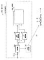
図1は、第1の実施の形態に係る表示システムの一構成例を表すものである。表示システム100は、立体視表示を行う表示システムである。なお、本開示の実施の形態に係る表示装置および表示方法は、本実施の形態により具現化されるので、併せて説明する。表示システム100は、表示装置1と、シャッタ眼鏡60とを備えている。
<1. First Embodiment>
[Configuration example]
(Overall configuration example)
FIG. 1 illustrates a configuration example of a display system according to the first embodiment. The display system 100 is a display system that performs stereoscopic display. Note that the display device and the display method according to the embodiment of the present disclosure are embodied by the present embodiment, and will be described together. The display system 100 includes the
表示装置1は、図1に示したように、制御部41と、バックライト駆動部42と、バックライト30と、表示駆動部50と、表示部20と、バリア駆動部43と、バリア部10と、シャッタ制御部44とを備えている。
As shown in FIG. 1, the
制御部41は、外部より供給される映像信号Sdispに基づいて、バックライト駆動部42、表示駆動部50、バリア駆動部43、およびシャッタ制御部44に対してそれぞれ制御信号を供給し、これらがお互いに同期して動作するように制御する回路である。具体的には、制御部41は、バックライト駆動部42に対してバックライト制御信号を供給し、表示駆動部50に対して映像信号Sdispに基づく映像信号Sを供給し、バリア駆動部43に対してバリア制御信号を供給し、シャッタ制御部44に対して制御信号を供給するようになっている。ここで、映像信号Sdispは、後述する左眼画像PLおよび右眼画像PRの画像情報を含むものである。
The
バックライト駆動部42は、制御部41から供給されるバックライト制御信号に基づいてバックライト30を駆動するものである。バックライト30は、面発光した光を表示部20に対して射出する機能を有している。バックライト30は、例えば、LED(Light Emitting Diode)や、CCFL(Cold Cathode Fluorescent Lamp)などを用いて構成されるものである。
The
表示駆動部50は、制御部41から供給される映像信号Sに基づいて表示部20を駆動するものである。表示部20は、この例では液晶表示部であり、液晶表示素子を駆動して、バックライト30から射出した光を変調することにより表示を行うようになっている。
The
バリア駆動部43は、制御部41から供給されるバリア制御信号に基づいてバリア部10を駆動するものである。バリア部10は、バックライト30から射出し表示部20を透過した光を透過(開状態)または遮断(閉状態)するものである。
The
表示装置1では、図1に示したように、バックライト30、表示部20、およびバリア部10が、この順に配置されている。つまり、バックライト30から射出した光は、表示部20およびバリア部10を介して、観察者に届くようになっている。
In the
シャッタ制御部44は、制御部41から供給される制御信号に基づいてシャッタ制御信号CTLを生成し、無線通信により、シャッタ眼鏡60に対して供給するものである。なお、この例では、シャッタ制御部44は、シャッタ制御信号CTLを無線通信により供給するものとしたが、これに限定されるものではなく、例えば、有線通信により供給してもよい。
The
シャッタ眼鏡60は、眼鏡型のシャッタ装置であり、観察者(図示せず)が用いることにより、立体視を可能とするものである。このシャッタ眼鏡60は、左眼シャッタ6Lおよび右眼シャッタ6Rを有している。左眼シャッタ6Lおよび右眼シャッタ6Rは、例えば液晶シャッタにより構成されている。これらの左眼シャッタ6Lおよび右眼シャッタ6Rの透過状態(開状態)および遮光状態(閉状態)は、シャッタ制御部44から供給されるシャッタ制御信号CTLにより制御されるようになっている。
The
(表示駆動部50および表示部20)
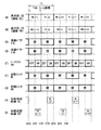
図2は、表示駆動部50の一構成例を表すものである。表示駆動部50は、タイミング制御部51と、ゲートドライバ52と、データドライバ53とを備えている。タイミング制御部51は、ゲートドライバ52およびデータドライバ53の駆動タイミングを制御するとともに、制御部41から供給された映像信号Sを映像信号S1としてデータドライバ53へ供給するものである。ゲートドライバ52は、タイミング制御部51によるタイミング制御に従って、表示部20内の画素Pix(後述)を行ごとに順次選択して、線順次走査するものである。データドライバ53は、表示部20の各画素Pixへ、映像信号S1に基づく画素信号を供給するものである。
(
FIG. 2 illustrates a configuration example of the
図3は、表示部20の一構成例を表すものであり、(A)は画素Pixの配列を示し、(B)は画素Pix内のサブ画素SPixの回路図の一例を示す。
FIG. 3 illustrates a configuration example of the
表示部20は、マトリクス状に形成された複数の画素Pixを有している。そして、各画素Pixは、赤色(R)、緑色(G)、青色(B)の3色に対応する3つのサブ画素SPixを有している。
The
また、表示部20には、図3(A)に示したように、表示画面の垂直方向Yに延伸する複数の領域DL,DRが設けられている。これらの複数の領域DL,DRは、水平方向Xに交互に配置されている。表示部20は、後述するように、領域DLに属する複数の画素Pixにより左眼画像PLを表示するとともに、領域DRに属する複数の画素Pixにより右眼画像PRを表示するようになっている。
Further, as shown in FIG. 3A, the
サブ画素SPixは、図3(B)に示したように、TFT(Thin Film Transistor)素子Trと、液晶素子LCと、保持容量素子Cとを備えている。TFT素子Trは、例えばMOS−FET(Metal Oxide Semiconductor-Field Effect Transistor)により構成されるものであり、ゲートがゲート線Gに接続され、ソースがデータ線Dに接続され、ドレインが液晶素子LCの一端と保持容量素子Cの一端に接続されている。液晶素子LCは、一端がTFT素子Trのドレインに接続され、他端は接地されている。保持容量素子Cは、一端がTFT素子Trのドレインに接続され、他端は保持容量線Csに接続されている。ゲート線Gはゲートドライバ52に接続され、データ線Dはデータドライバ53に接続されている。
As shown in FIG. 3B, the sub-pixel SPix includes a TFT (Thin Film Transistor) element Tr, a liquid crystal element LC, and a storage capacitor element C. The TFT element Tr is configured by, for example, a MOS-FET (Metal Oxide Semiconductor-Field Effect Transistor), the gate is connected to the gate line G, the source is connected to the data line D, and the drain is the liquid crystal element LC. One end and one end of the storage capacitor element C are connected. The liquid crystal element LC has one end connected to the drain of the TFT element Tr and the other end grounded. The storage capacitor element C has one end connected to the drain of the TFT element Tr and the other end connected to the storage capacitor line Cs. The gate line G is connected to the
(バリア部10およびバリア駆動部43)
図4は、バリア部10の一構成例を表すものであり、(A)はバリア部10の平面図を示し、(B)は(A)のバリア部10のIV−IV矢視方向の断面構成を示す。なお、この例では、バリア部10はノーマリーブラック動作を行うものとする。つまり、バリア部10は、駆動されていない状態では光を遮断するものとする。
(
4A and 4B show a configuration example of the
バリア部10は、光を透過または遮断する液晶バリア11L,11Rを有している。液晶バリア11L,11Rは、垂直方向Yに延在するように設けられるとともに、水平方向Xに交互に配置されている。これらの液晶バリア11L,11Rは、透過状態(開状態)と遮断状態(閉状態)との間で時分割的に切り換わるように動作(開閉動作)するものである。
The
バリア部10は、図4(B)に示したように、例えばガラス等からなる透明基板13と透明基板16との間に液晶層19を備えたものである。この例では、透明基板13が光入射側、透明基板16が光出射側に配置されている。透明基板13の液晶層19側の面、および透明基板16の液晶層19側の面には、例えばITOなどからなる透明電極層15,17がそれぞれ形成されている。これらの透明電極層15,17の液晶層19側の面には、図示しない配向膜が形成されている。液晶層19は、例えば、VA(垂直配向)モードの液晶が用いられる。透明基板13の光入射側および透明基板16の光出射側には、偏光板14,18が貼り合わせられている。
As shown in FIG. 4B, the
透明電極層15は、複数の透明電極12L,12Rを有している。そして、透明電極層17は、各透明電極12L,12Rに共通の電極として設けられている。この例では、透明電極層17には0Vが印加されている。透明電極層15の透明電極12Lと、液晶層19および透明電極層17におけるその透明電極12Lに対応する部分とは、液晶バリア11Lを構成している。同様に、透明電極層15の透明電極12Rと、液晶層19および透明電極層17におけるその透明電極12Rに対応する部分とは、液晶バリア11Rを構成している。このような構成により、バリア部10では、透明電極12L,12Rに電圧を選択的に印加し、液晶層19がその電圧に応じた液晶配向になることにより、液晶バリア11L,11R毎の開閉動作を行うことができるようになっている。
The
なお、この例では、バリア部10はノーマリーブラック動作を行うものとしたが、これに限定されるものではなく、これに代えて、例えばノーマリーホワイト動作を行うものであってもよい。
In this example, the
図5は、バリア部10の液晶バリア11L,11Rと、表示部20の画素Pixの配置との関係を表すものである。図5に示したように、液晶バリア11Lは、表示部20における領域DLと対応するように配置されており、同様に、液晶バリア11Rは、表示部20における領域DRと対応するように配置されている。すなわち、表示部20は、液晶バリア11Lに対応する領域DLにおいて左眼画像PLを表示するとともに、液晶バリア11Rに対応する領域DRにおいて右眼画像PRを表示するようになっている。
FIG. 5 illustrates the relationship between the
ここで、領域DL,DRは、本開示における「サブ領域」の一具体例に対応する。 Here, the regions DL and DR correspond to a specific example of “sub-region” in the present disclosure.
[動作および作用]
続いて、本実施の形態の表示システム100の動作および作用について説明する。
[Operation and Action]
Subsequently, the operation and action of the display system 100 of the present embodiment will be described.
(全体動作概要)
まず、図1を参照して、表示システム100の全体動作概要を説明する。制御部41は、外部より供給される映像信号Sdispに基づいて、バックライト駆動部42、表示駆動部50、バリア駆動部43、およびシャッタ制御部44に対してそれぞれ制御信号を供給し、これらがお互いに同期して動作するように制御する。バックライト駆動部42は、バックライト30を駆動する。バックライト30は、面発光した光を表示部20に対して射出する。表示駆動部50は、表示部20を駆動する。表示部20は、バックライト30から射出した光を変調することにより表示を行う。バリア駆動部43は、バリア部10を駆動する。バリア部10は、バックライト30から射出し表示部20を透過した光を透過(開状態)または遮断(閉状態)する。シャッタ制御部44は、シャッタ制御信号CTLを生成するとともに、そのシャッタ制御信号CTLをシャッタ眼鏡60に対して供給する。シャッタ眼鏡60の左眼シャッタ6Lおよび右眼シャッタ6Rは、そのシャッタ制御信号CTLに基づいて開閉動作する。
(Overview of overall operation)
First, an overall operation overview of the display system 100 will be described with reference to FIG. The
図6は、表示システム100の全体動作を模式的に表すものである。図6において、(A)は左眼画像PLを表示したときの動作を示し、(B)は右眼画像PRを表示したときの動作を示す。表示装置1が左眼画像PLを表示しているとき、シャッタ眼鏡60では、図6(A)に示したように、左眼シャッタ6Lが開状態となるとともに、右眼シャッタ6Rが閉状態となる。このとき、観察者9は左眼9Lで左眼画像PLを見る。一方、表示装置1が右眼画像PRを表示しているとき、シャッタ眼鏡60では、図6(B)に示したように、左眼シャッタ6Lが閉状態となるとともに、右眼シャッタ6Rが開状態となる。このとき、観察者9は右眼9Rで右眼画像PRを見る。これらの動作を交互に繰り返すと、左眼画像PLと右眼画像PRとの間には視差があるため、観察者9は、これらの一連の画像からなる映像を奥行きのある立体的な映像として認識することができる。
FIG. 6 schematically illustrates the overall operation of the display system 100. 6A shows the operation when the left eye image PL is displayed, and FIG. 6B shows the operation when the right eye image PR is displayed. When the
(詳細動作)
次に、表示システム100の詳細動作について説明する。
(Detailed operation)
Next, detailed operation of the display system 100 will be described.
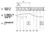
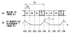
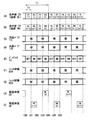
図7は、表示システム100の一動作例を表すものであり、(A),(B)は表示部20における領域DL,DRの動作をそれぞれ示し、(C),(D)はバリア部10における液晶バリア11L,11Rの動作をそれぞれ示し、(E)はバックライト30の動作を示し、(F),(G)はシャッタ眼鏡60における左眼シャッタ6Lおよび右眼シャッタ6Rの動作をそれぞれ示し、(H),(I)は観察者の左眼視認映像ULおよび右眼視認映像URをそれぞれ示す。図7(A),(B)において、“PL”は、表示部20が左眼画像PLを表示している状態を示し、“PR”は、表示部20が右眼画像PRを表示している状態を示している。なお、例えば“PL(n)”の“n”は、フレーム画像を区別するために説明の便宜上導入したインデックスである。
FIG. 7 shows an operation example of the display system 100, where (A) and (B) show the operations of the regions DL and DR in the
表示システム100では、表示装置1は、液晶バリア11L,11Rが独立して開閉動作することにより、左眼画像PLおよび右眼画像PRを時分割的に表示する。そして、シャッタ眼鏡60の左眼シャッタ6Lおよび右眼シャッタ6Rが、左眼画像PLおよび右眼画像PRの表示に同期して開閉動作することにより、観察者は、一連の左眼画像PLを左眼視認映像ULとして視認するとともに、一連の右眼画像PRを右眼視認映像URとして視認する。以下に、この動作の詳細を説明する。
In the display system 100, the
表示装置1では、まず、タイミングt0〜t4の期間において、表示部20が、4つ分のフレーム期間T0に対応する期間(繰返表示期間T1)にわたり、同じ左眼画像PL(n)を領域DLに繰り返し表示する(図7(A))。ここで、繰返表示期間T1は、例えば、16.7[msec](=1/60[Hz])であり、フレーム期間T0は、4.2[msec](=T1/4)である。すなわち、この例では、表示装置1はいわゆる4倍速の液晶表示装置である。そして、タイミングt2〜t4の期間において、液晶バリア11Lが開状態(透過状態)になる(図7(C))。なお、この例では、液晶バリア11Lの液晶分子の応答特性を考慮して、タイミングt2から液晶バリア11Lを開状態にしているが、これに限定されるものではなく、応答速度が速い場合には、例えばタイミングt3から開状態にしてもよい。そして、タイミングt3〜t4の期間において、バックライト30がオン状態になる(図7(E))。これにより、表示装置1は、タイミングt3〜t4の期間において、左眼画像PL(n)を表示する。
In the
一方、シャッタ眼鏡60では、左眼シャッタ6Lが、タイミングt2〜t4の期間において開状態(透過状態)になる(図7(F))。なお、この例では、液晶バリア11Lの場合と同様に、左眼シャッタ6Lにおける液晶分子の応答特性を考慮して、タイミングt2から左眼シャッタ6Lを開状態にしているが、これに限定されるものではなく、応答速度が速い場合には、例えばタイミングt3から開状態にしてもよい。これにより、観察者は、タイミングt3〜t4の期間において、左眼画像PL(n)を視認することができる(図7(H))。
On the other hand, in the
同様に、表示装置1では、タイミングt2〜t6の期間において、表示部20が、4つ分のフレーム期間T0に対応する期間(繰返表示期間T1)にわたり、同じ右眼画像PR(n)を領域DRに繰り返し表示する(図7(B))。そして、タイミングt4〜t6の期間において、液晶バリア11Rが開状態(透過状態)になり、タイミングt5〜t6の期間において、バックライト30がオン状態になる(図7(D),(E))。これにより、表示装置1は、タイミングt5〜t6の期間において、右眼画像PR(n)を表示する。一方、シャッタ眼鏡60では、右眼シャッタ6Rが、タイミングt4〜t6の期間において開状態(透過状態)になる(図7(G))。これにより、観察者は、タイミングt5〜t6の期間において、右眼画像PR(n)を視認することができる(図7(I))。
Similarly, in the
以上の動作を繰り返すことにより、観察者は、一連の左眼画像PLを左眼視認映像ULとして視認するとともに(図7(H))、一連の右眼画像PRを右眼視認映像URとして視認することにより(図7(I))、表示システム100に表示される映像を立体的な映像として視認することができる。 By repeating the above operation, the observer visually recognizes the series of left eye images PL as the left eye visual image UL (FIG. 7H) and visually recognizes the series of right eye images PR as the right eye visual image UR. By doing so (FIG. 7I), the video displayed on the display system 100 can be visually recognized as a stereoscopic video.
表示システム100では、同一の左眼画像PLおよび右眼画像PRを、4つ分のフレーム期間T0に対応する期間(繰返表示期間T1)にわたり繰り返して表示し、そのうちの最後のフレーム期間T0において、バックライト30を点灯して、観察者がその画像を視認するようにしている。これにより、例えば、表示部20の液晶素子LCの応答特性が遅い場合でも、液晶素子LCが十分に応答した後に、画像を観察者に視認させることができる。以下に、その詳細を説明する。
In the display system 100, the same left-eye image PL and right-eye image PR are repeatedly displayed over a period (repetitive display period T1) corresponding to four frame periods T0, and in the last frame period T0 among them. The
図8は、表示部20における液晶素子LCの応答特性を表すものであり、(A)は表示部20における領域DLの動作を示し、(B)は領域DLにおけるサブ画素SPixの光の透過率Tを示し、(C)は左眼視認映像ULを示す。なお、この例では、左眼画像PLについて説明するが、右眼画像PRについても同様である。
8A and 8B show response characteristics of the liquid crystal element LC in the
表示部20は、タイミングt0において、左眼画像PL(n)の表示を開始する(図8(A))。このとき、表示部20のサブ画素SPixでは、液晶素子LCの応答速度が遅い場合には、図8(B)に示したように、その光の透過率Tが応答するまでに、複数(この例では3つ分)のフレーム期間T0にわたるほどの応答時間τがかかってしまうおそれがある。しかしながら、この表示システム100では、繰返表示期間T1のうちの最後のフレーム期間T0(タイミングt3〜t4の期間)において、観察者が左眼画像PL(n)を視認するようにしたので、液晶素子LCが十分に応答した後に観察者がその画像を視認することができるため、画質の低下を抑えることができる。
The
(比較例)
次に、比較例と対比して、本実施の形態の作用を説明する。
(Comparative example)
Next, the operation of the present embodiment will be described in comparison with the comparative example.
図9は、本比較例に係る表示システム100Rの一構成例を表すものである。表示システム100Rは、表示装置1Rを備えている。表示装置1Rは、本実施の形態に係る表示装置1(図1)において、バリア部10を省いたものである。この表示装置1Rは、バリア部を用いずに、左眼画像PLおよび右眼画像PRを時分割的に表示するものである。すなわち、本実施の形態に係る表示装置1は、表示部20が、領域DL,DRに左眼画像PLおよび右眼画像PRをそれぞれ表示するとともに、液晶バリア11L,11Rが独立して開閉動作することにより、この左眼画像PLおよび右眼画像PRを時分割的に表示したが、本比較例に係る表示装置1Rは、表示画面全面に左眼画像PLおよび右眼画像PRを時分割的に表示するものである。
FIG. 9 illustrates a configuration example of the display system 100R according to this comparative example. The display system 100R includes a display device 1R. The display device 1R is obtained by omitting the
図10は、表示システム100Rの一動作例を表すものであり、(A)は表示部20の動作を示し、(B)はバックライト30の動作を示し、(C),(D)はシャッタ眼鏡60における左眼シャッタ6Lおよび右眼シャッタ6Rの動作をそれぞれ示し、(E),(F)は観察者の左眼視認映像ULおよび右眼視認映像URをそれぞれ示す。
FIG. 10 illustrates an operation example of the display system 100R. (A) illustrates the operation of the
表示装置1Rでは、まず、タイミングt10〜t12の期間において、表示部20が、2つ分のフレーム期間T0に対応する期間(繰返表示期間T1R)にわたり、同じ左眼画像PL(n)を表示画面全面に繰り返し表示する(図10(A))。ここで、繰返表示期間T1Rは、例えば、8.3[msec]である。そして、タイミングt11〜t12の期間において、バックライト30がオン状態になる(図10(B))。これにより、表示装置1Rは、タイミングt11〜t12の期間において、左眼画像PL(n)を表示する。一方、シャッタ眼鏡60では、左眼シャッタ6Lが、タイミングt10〜t12の期間において開状態(透過状態)になる(図10(C))。これにより、観察者は、タイミングt11〜t12の期間において、左眼画像PL(n)を視認する(図10(E))。
In the display device 1R, first, the
次に、表示装置1Rでは、タイミングt12〜t14の期間において、表示部20が、2つ分のフレーム期間T0に対応する期間(繰返表示期間T1R)にわたり、同じ右眼画像PR(n)を表示画面全面に繰り返し表示する(図10(A))。そして、タイミングt13〜t14の期間において、バックライト30がオン状態になる(図10(B))。これにより、表示装置1Rは、タイミングt13〜t14の期間において、右眼画像PR(n)を表示する。一方、シャッタ眼鏡60では、右眼シャッタ6Rが、タイミングt13〜t14の期間において開状態(透過状態)になる(図10(D))。これにより、観察者は、タイミングt13〜t14の期間において、右眼画像PR(n)を視認する(図10(F))。
Next, in the display device 1R, in the period from the timing t12 to t14, the
本比較例に係る表示システム100Rでは、同一の左眼画像PLおよび右眼画像PRを2つ分のフレーム期間T0に対応する期間(繰返表示期間T1R)にわたり繰り返して表示し、2番目のフレーム期間T0において、バックライト30を点灯して、観察者がその画像を視認するようにしている。すなわち、本比較例に係る表示装置100Rでは、本実施の形態に係る表示システム100と比べ、画像の表示を開始してから観察者が画像を視認するまでの時間が短くなっている。これにより、例えば、表示部20における液晶素子LCの応答特性が遅い場合には、液晶素子LCが十分に応答する前に、観察者が画像を視認することとなり、画像表示が安定するまでの過渡状態が表示されることになるため、画質が低下してしまう。また、表示システム100Rでは、表示部20は、左眼画像PLと右眼画像PRとを交互に表示しているため、左眼画像PLと右眼画像PRとが互いに混ざり合う、いわゆるクロストークが生じるおそれがある。具体的には、例えばタイミングt10において左眼画像PLの表示を開始した後、液晶素子LCが十分に応答する前に、タイミングt12において次の右眼画像PRの表示を開始する場合には、右眼画像PRを表示する際の液晶素子LCの状態が、直前の左眼画像PLを表示した際の液晶素子LCの状態の影響を受けるおそれがある。このようにしてクロストークが生じた場合には、さらに画質が低下してしまう。
In the display system 100R according to this comparative example, the same left-eye image PL and right-eye image PR are repeatedly displayed over a period (repetitive display period T1R) corresponding to two frame periods T0, and the second frame. In the period T0, the
一方、本実施の形態に係る表示システム100では、バリア部10を設け、左眼画像PLを、液晶バリア11Lに対応する領域DLに表示するとともに、右眼画像PRを、液晶バリア11Rに対応する領域DRに表示するようにしている。すなわち、左眼画像PLと右眼画像PRとを、互いに異なる領域DL,DRに表示するようにしたので、表示部20の液晶素子LCの応答特性に起因するクロストークを低減することができる。さらに、同一の左眼画像PLおよび右眼画像PRを繰り返し表示する期間(繰返表示期間T1)を長くすることができるため、画像の表示を開始してから観察者が画像を視認するまでの時間をかせぐことができる。これにより、液晶素子LCが十分に応答した後に観察者が画像を視認することができるため、画質の低下を抑えることができる。
On the other hand, in the display system 100 according to the present embodiment, the
なお、表示システム100では、左眼画像PLと右眼画像PRとを、表示部20における互いに異なる領域DL,DRに表示する。つまり、左眼画像PLおよび右眼画像PRの水平方向Xの画素数は、表示部20の表示画面全体における水平方向Xの画素数の半分程度であることから、表示画像の水平方向Xの解像度が低下する。よって、表示システム100は、このような解像度の低下が問題にならない用途に適用することができる。また、近年、高い解像度の表示パネルが開発されており、これを用いることにより、この解像度の低下に起因する画質の低下を抑えることができる。具体的には、近年、例えば、フルHD(High Definition)表示用の表示パネル(1920ピクセル×1080ピクセル)の4倍の解像度を有する、いわゆる4k2kの表示パネル(3840ピクセル×2160ピクセル)が開発されており、この高解像度の表示パネルを表示システム100に適用することにより、左眼画像PLおよび右眼画像PRをそれぞれHDの分解能で表示することが可能となる。
In the display system 100, the left eye image PL and the right eye image PR are displayed in different areas DL and DR on the
[効果]
以上のように本実施の形態では、左眼画像と右眼画像とを、表示部において互いに異なる領域に表示したので、クロストークを低減することができる。
[effect]
As described above, in the present embodiment, the left eye image and the right eye image are displayed in different areas on the display unit, so that crosstalk can be reduced.
また、本実施の形態では、同一の左眼画像PLおよび右眼画像PRを繰り返し表示する期間を長くしたので、画質の低下を抑えることができる。 In the present embodiment, since the period for repeatedly displaying the same left-eye image PL and right-eye image PR is lengthened, deterioration in image quality can be suppressed.
[変形例1−1]
上記実施の形態では、表示装置1は4倍速の液晶表示装置としたが、これに限定されるものではなく、例えば、図11に示したように、2倍速であってもよいし、また、例えば、図12に示したように、6倍速であってもよい。図11に示した、2倍速の表示装置を備えた表示システムでは、フレーム期間T0Aは、例えば、8.3[msec](=1/2/60[Hz])であり、繰返表示期間T1(例えば、16.7[msec]=1/60[Hz])において、左眼画像PLおよび右眼画像PRがそれぞれ2回繰り返して表示される。また、図12に示した、6倍速の表示装置を備えた表示システムでは、フレーム期間T0Bは、2.8[msec](=1/6/60[Hz])であり、繰返表示期間T1において、左眼画像PLおよび右眼画像PRがそれぞれ6回繰り返して表示される。なお、図12では、繰返表示期間T1の6つのフレーム期間T0Bのうちの最後のフレーム期間T0Bにおいてバックライト30を点灯するようにしたが、これに限定されるものではなく、例えば、図13に示したように、繰返表示期間T1の6つのフレーム期間T0Bのうちの最後の2つのフレーム期間T0Bにおいてバックライト30を点灯するようにしてもよい。これらの場合でも、上記実施の形態に係る表示システム100の場合と同様の効果を得ることができる。
[Modification 1-1]
In the above embodiment, the
<2.第2の実施の形態>
次に、第2の実施の形態に係る表示システム200について説明する。本実施の形態は、左眼画像PLおよび右眼画像PRとともに、黒画像を表示するものである。すなわち、本実施の形態に係る表示システム200は、図1において、黒画像を生成する制御部45を用いて表示装置2を構成したものである。その他の構成は、上記第1の実施の形態(図1)と同様である。なお、上記第1の実施の形態に係る表示システム100と実質的に同一の構成部分には同一の符号を付し、適宜説明を省略する。
<2. Second Embodiment>
Next, a display system 200 according to the second embodiment will be described. In the present embodiment, a black image is displayed together with the left eye image PL and the right eye image PR. That is, the display system 200 according to the present embodiment is configured by configuring the
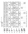
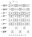
図14は、表示システム200の一動作例を表すものであり、(A),(B)は表示部20における領域DL,DRの動作をそれぞれ示し、(C),(D)はバリア部10における液晶バリア11L,11Rの動作をそれぞれ示し、(E)はバックライト30の動作を示し、(F),(G)はシャッタ眼鏡60における左眼シャッタ6Lおよび右眼シャッタ6Rの動作をそれぞれ示し、(H),(I)は観察者の左眼視認映像ULおよび右眼視認映像URをそれぞれ示す。図14(A),(B)において、“Bk”は、表示部20が黒画像を表示している状態を示している。
FIG. 14 shows an operation example of the display system 200, where (A) and (B) show the operations of the regions DL and DR in the
表示装置2では、まず、タイミングt50〜t53の期間において、表示部20が、3つ分のフレーム期間T0に対応する期間にわたり、制御部45が生成した黒画像を領域DLに繰り返し表示した後、タイミングt53〜t54の期間において、左眼画像PL(n)を領域DLに表示する(図14(A))。そして、タイミングt52〜t54の期間において、液晶バリア11Lが開状態(透過状態)になり、タイミングt53〜t54の期間において、バックライト30がオン状態になる(図14(C),(E))。これにより、表示装置2は、タイミングt53〜t54の期間において、左眼画像PL(n)を表示する。一方、シャッタ眼鏡60では、左眼シャッタ6Lが、タイミングt52〜t54の期間において開状態(透過状態)になる(図14(F))。これにより、観察者は、タイミングt53〜t54の期間において、左眼画像PL(n)を視認することができる(図14(H))。
In the
同様に、表示装置2では、タイミングt52〜t55の期間において、表示部20が、3つ分のフレーム期間T0に対応する期間にわたり、制御部45が生成した黒画像を領域DRに繰り返し表示した後、タイミングt55〜t56の期間において、右眼画像PL(n)を領域DRに表示する(図14(B))。そして、タイミングt54〜t56の期間において、液晶バリア11Rが開状態(透過状態)になり、タイミングt53〜t54の期間において、バックライト30がオン状態になる((図14(D),(E))。これにより、表示装置2は、タイミングt55〜t56の期間において、右眼画像PR(n)を表示する。一方、シャッタ眼鏡60では、右眼シャッタ6Rが、タイミングt54〜t56の期間において開状態(透過状態)になる(図14(G))。これにより、観察者は、タイミングt55〜t56の期間において、右眼画像PR(n)を視認することができる(図14(I))。
Similarly, in the
以上の動作を繰り返すことにより、観察者は、一連の左眼画像PLを左眼視認映像ULとして視認するとともに(図14(H))、一連の右眼画像PRを右眼視認映像URとして視認することにより(図14(I))、表示システム200に表示される映像を立体的な映像として視認することができる。 By repeating the above operation, the observer visually recognizes the series of left eye images PL as the left eye visual image UL (FIG. 14H) and visually recognizes the series of right eye images PR as the right eye visual image UR. By doing so (FIG. 14I), the video displayed on the display system 200 can be visually recognized as a stereoscopic video.
図15は、表示部20における液晶素子LCの応答特性を表すものであり、(A)は表示部20における領域DLの動作を示し、(B)は領域DLにおけるサブ画素SPixの光の透過率Tを示す。
15A and 15B show the response characteristics of the liquid crystal element LC in the
表示部20は、タイミングt53〜t54の期間において、左眼画像PL(n)の表示を行い、タイミングt54〜t57の期間において、黒画像の表示を行う(図15(A))。このタイミングt54〜t57の期間において、表示部20のサブ画素SPixでは、応答時間τを経て液晶素子LCが十分に応答し、光の透過率Tが十分に低くなる。そして、タイミングt57において、光の透過率Tが十分に低くなった状態から、次の左眼画像PL(n+1)の表示を行う。すなわち、画像表示を開始するタイミングでは、常に、光の透過率Tが十分に低くなっている。このように、表示システム200では、黒画像を表示するようにしたので、常に同じ状態から画像表示を開始するため、ある画像の表示が、次の画像表示に影響を与えるおそれを低減することができ、画質の低下を抑えることができる。
The
以上のように本実施の形態では、黒画像を表示するようにしたので、画質の低下を低減することができる。その他の効果は、上記第1の実施の形態の場合と同様である。 As described above, in the present embodiment, since a black image is displayed, it is possible to reduce deterioration in image quality. Other effects are the same as in the case of the first embodiment.
[変形例2−1]
上記実施の形態では、表示部20が、左眼画像PLまたは右眼画像PRの表示を1つ分のフレーム期間T0において行うようにしたが、これに限定されるものではなく、例えば、図16に示したように、2つ分のフレーム期間において繰り返し表示してもよい。
[Modification 2-1]
In the above embodiment, the
[変形例2−2]
上記実施の形態では、表示部20を液晶表示素子により構成したが、これに限定されるものではなく、これに代えて、自発光型の表示素子により構成してもよい。以下にその詳細を説明する。
[Modification 2-2]
In the said embodiment, although the
図17は、本変形例に係る表示システム200Aの一構成例を表すものである。表示システム200Aは、表示装置2Aを備えている。表示装置2Aは、表示部20Aと、制御部45Aとを備えている。
FIG. 17 illustrates a configuration example of the display system 200A according to the present modification. The display system 200A includes a display device 2A. The display device 2A includes a display unit 20A and a
表示部20Aは、自発光型の表示素子により構成したものであり、例えばプラズマ表示装置である。制御部45Aは、外部より供給される映像信号Sdispに基づいて、表示駆動部50、バリア駆動部43、およびシャッタ制御部44を制御するものである。すなわち、表示装置2Aは、表示部20Aが自発光型の表示素子であるため、上記実施の形態に係る表示装置2とは異なり、バックライトおよびバックライト駆動部を省いている。
The display unit 20A is configured by a self-luminous display element, and is, for example, a plasma display device. The
図18は、表示システム200Aの一動作例を表すものであり、(A),(B)は表示部20における領域DL,DRの動作をそれぞれ示し、(C),(D)はバリア部10における液晶バリア11L,11Rの動作をそれぞれ示し、(E),(F)はシャッタ眼鏡60における左眼シャッタ6Lおよび右眼シャッタ6Rの動作をそれぞれ示し、(G),(H)は観察者の左眼視認映像ULおよび右眼視認映像URをそれぞれ示す。
FIG. 18 shows an operation example of the display system 200A. (A) and (B) show the operations of the regions DL and DR in the
表示装置2Aでは、タイミングt70〜t73の期間において、表示部20Aが、3つ分のフレーム期間T0に対応する期間にわたり、制御部45Aが生成した黒画像を領域DLに繰り返し表示した後、タイミングt73〜t74の期間において、左眼画像PL(n)を領域DLに表示する(図18(A))。そして、タイミングt72〜t74の期間において、液晶バリア11Lおよび左眼シャッタ6Lが開状態(透過状態)になり(図18(C),(E))、観察者は、タイミングt73〜t74の期間において、左眼画像PL(n)を視認する(図18(G))。
In the display device 2A, during the period from timing t70 to t73, the display unit 20A repeatedly displays the black image generated by the
同様に、表示装置2Aでは、タイミングt72〜t75の期間において、表示部20Aが、3つ分のフレーム期間T0に対応する期間にわたり、制御部45Aが生成した黒画像を領域DRに繰り返し表示した後、タイミングt75〜t76の期間において、右眼画像PR(n)を領域DRに表示する(図18(B))。そして、タイミングt74〜t76の期間において、液晶バリア11Rおよび右眼シャッタ6Rが開状態(透過状態)になり(図18(D),(F))、観察者は、タイミングt75〜t76の期間において、右眼画像PR(n)を視認する(図18(H))。
Similarly, in the display device 2A, after the display unit 20A repeatedly displays the black image generated by the
この場合でも、上記実施の形態に係る表示システム200の場合と同様の効果を得ることができる。 Even in this case, the same effect as that of the display system 200 according to the above embodiment can be obtained.
[変形例2−3]
また、上記実施の形態では、表示装置2は4倍速の液晶表示装置としたが、これに限定されるものではなく、変形例1−1と同様に、例えば、2倍速や6倍速であってもよい。
[Modification 2-3]
In the above embodiment, the
<3.第3の実施の形態>
次に、第3の実施の形態に係る表示システム300について説明する。本実施の形態は、上記第1の実施の形態に係る表示システム100を、複数の観察者が異なる映像を同時に観察することができるマルチビューシステムに適用したものである。なお、上記第1の実施の形態に係る表示システム100と実質的に同一の構成部分には同一の符号を付し、適宜説明を省略する。以下、二人の観察者9A,9Bが映像を観察するマルチビューシステムを例に説明する。
<3. Third Embodiment>
Next, a display system 300 according to the third embodiment will be described. In the present embodiment, the display system 100 according to the first embodiment is applied to a multi-view system in which a plurality of viewers can simultaneously observe different images. In addition, the same code | symbol is attached | subjected to the component substantially the same as the display system 100 which concerns on the said 1st Embodiment, and description is abbreviate | omitted suitably. Hereinafter, a multi-view system in which two
図19は、本実施の形態に係る表示システム300の一構成例を表すものである。表示システム300は、表示装置3と、2つのシャッタ眼鏡60A,60Bとを備えている。表示装置3は、映像信号Sdisp2に基づいて、観察者9Aが見る画像PA、および観察者9Bが見る画像PBを表示するものである。ここで、映像信号Sdisp2は、画像PAおよび画像PBの画像情報を含むものである。シャッタ眼鏡60A,60Bは、観察者9A,9Bがそれぞれ身につけるものである。
FIG. 19 illustrates a configuration example of the display system 300 according to the present embodiment. The display system 300 includes the
表示装置3は、シャッタ制御部46を有している。シャッタ制御部46は、2つのシャッタ制御信号CTLA,CTLBを生成し、シャッタ眼鏡60Aに対してシャッタ制御信号CTLAを供給するとともに、シャッタ眼鏡60Bに対してシャッタ制御信号CTLBを供給するものである。シャッタ眼鏡60Aの左眼シャッタ6ALおよび右眼シャッタ6ARは、シャッタ制御信号CTLAに基づいて、開閉動作するものである。その際、左眼シャッタ6ALおよび右眼シャッタ6ARは、同時に開閉動作するようになっている。同様に、シャッタ眼鏡60Bの左眼シャッタ6BLおよび右眼シャッタ6BRは、シャッタ制御信号CTLBに基づいて、開閉動作するものである。その際、左眼シャッタ6BLおよび右眼シャッタ6BRは、同時に開閉動作するようになっている。
The
図20は、表示システム300の全体動作を模式的に表すものである。図20において、(A)は観察者9Aのための画像PAを表示したときの動作を示し、(B)は観察者9Bのための画像9Bを表示したときの動作を示す。表示装置3が画像PAを表示している場合、図20(A)に示したように、シャッタ眼鏡60Aの左眼シャッタ6ALおよび右眼シャッタ6ARが開状態となるとともに、シャッタ眼鏡60Bの左眼シャッタ6BLおよび右眼シャッタ6BRが閉状態となる。このとき、観察者9Aが画像PAを見ることとなる。一方、表示装置3が画像PBを表示している場合、図20(B)に示したように、シャッタ眼鏡60Aの左眼シャッタ6ALおよび右眼シャッタ6ARが閉状態となるとともに、シャッタ眼鏡60Bの左眼シャッタ6BLおよび右眼シャッタ6BRが開状態となる。このとき、観察者9Bが画像PBを見ることとなる。これらの動作を交互に繰り返すことにより、画像PAからなる映像を観察者9Aが見るとともに、画像PBからなる映像を観察者9Bが見ることができ、1つの表示装置に表示される複数の映像のそれぞれを複数の観察者が見ることができる、マルチビューシステムを実現することができる。
FIG. 20 schematically illustrates the overall operation of the display system 300. 20A shows the operation when the image PA for the
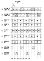
図21は、表示システム300の一動作例を表すものであり、(A),(B)は表示部20における領域DL,DRの動作をそれぞれ示し、(C),(D)はバリア部10における液晶バリア11L,11Rの動作をそれぞれ示し、(E)はバックライト30の動作を示し、(F),(G)はシャッタ眼鏡60A,60Bの動作をそれぞれ示し、(H),(I)は観察者9Aの視認映像UAおよび観察者9Bの視認映像UBをそれぞれ示す。図21(A),(B)において、“PA”は、表示部20が画像PAを表示している状態を示し、“PB”は、表示部20が画像PBを表示している状態を示している。
FIG. 21 shows an operation example of the display system 300. (A) and (B) show the operations of the regions DL and DR in the
表示装置3では、まず、タイミングt80〜t84の期間において、表示部20が、4つ分のフレーム期間T0に対応する期間(繰返表示期間T1)にわたり、同じ画像PA(n)を領域DLに繰り返し表示する(図21(A))。そして、タイミングt82〜t84の期間において、液晶バリア11Lが開状態(透過状態)になり、タイミングt83〜t84の期間において、バックライト30がオン状態になる(図21(C),(E))。これにより、表示装置3は、画像PA(n)を、タイミングt83〜t84の期間において表示する。一方、シャッタ眼鏡60Aでは、左眼シャッタ6ALおよび右眼シャッタ6ARが、タイミングt82〜t84の期間において開状態(透過状態)になる(図21(F))。これにより、観察者は、タイミングt83〜t84の期間において、画像PA(n)を視認することができる(図21(H))。
In the
同様に、表示装置3では、まず、タイミングt82〜t86の期間において、表示部20が、4つ分のフレーム期間T0に対応する期間(繰返表示期間T1)にわたり、同じ画像PB(n)を領域DRに繰り返し表示する(図21(B))。そして、タイミングt84〜t86の期間において、液晶バリア11Rが開状態(透過状態)になり、タイミングt5〜t6の期間において、バックライト30がオン状態になる(図21(D),(E))。これにより、表示装置3は、画像PB(n)を、タイミングt85〜t86の期間において表示する。一方、シャッタ眼鏡60Bでは、左眼シャッタ6BLおよび右眼シャッタ6BRが、タイミングt84〜t86の期間において開状態(透過状態)になる(図21(G))。これにより、観察者は、タイミングt85〜t86の期間において、画像PB(n)を視認することができる(図21(I))。
Similarly, in the
以上の動作を繰り返すことにより、観察者9Aは、一連の画像PAを視認映像UAとして視認し(図21(H))、同時に、観察者9Bは、一連の画像PBを視認映像UBとして視認することができる(図21(I))。
By repeating the above operation, the
以上のように本実施の形態では、複数のシャッタ眼鏡を備え、画像PA,PBを表示するとともに、各シャッタ眼鏡の左眼シャッタと右眼シャッタとを同時に開閉動作するようにしたので、マルチビューシステムを実現することができる。その他の効果は、上記第1の実施の形態の場合と同様である。 As described above, in the present embodiment, a plurality of shutter glasses are provided, the images PA and PB are displayed, and the left eye shutter and the right eye shutter of each shutter glasses are simultaneously opened and closed. A system can be realized. Other effects are the same as in the case of the first embodiment.
[変形例3−1]
上記実施の形態では、表示システム100をマルチビューシステムに適用したが、これに限定されるものではなく、これに代えて、例えば、表示システム200をマルチビューシステムに適用してもよい。
[Modification 3-1]
In the above-described embodiment, the display system 100 is applied to the multi-view system. However, the present invention is not limited to this. For example, the display system 200 may be applied to the multi-view system.
以上、いくつかの実施の形態および変形例を挙げて本技術を説明したが、本技術はこれらの実施の形態等には限定されず、種々の変形が可能である。 The present technology has been described above with some embodiments and modifications. However, the present technology is not limited to these embodiments and the like, and various modifications are possible.
例えば、上記の各実施の形態では、表示部20に領域DL,DRを設けるとともに、バリア部10のこれらに対応する位置に液晶バリア11L,11Rを設けるようにしたが、これに限定されるものではなく、領域および液晶バリアをより多く設けてもよい。以下に、上記第1の実施の形態に係る表示システム100に本変形例を適用した場合について説明する。
For example, in each of the above embodiments, the
図22は、本変形例に係るバリア部70の液晶バリアと、表示部20の画素Pixの配置との関係を表すものである。図22に示したように、バリア部70は、液晶バリア11L1,11R1,11L2,11R2を有している。これらの液晶バリア11L1,11R1,11L2,11R2は、垂直方向Yに延在するように設けられるとともに、水平方向Xにこの順で巡回するように配置されている。表示部20には、これらの液晶バリア11L1,11R1,11L2,11R2に対応する位置に、領域DL1,DR1,DL2,DR2が設けられている。表示部20は、領域DL1,DL2において左眼画像PLを表示するとともに、領域DR1,DR2おいて右眼画像PRを表示するようになっている。
FIG. 22 shows the relationship between the liquid crystal barrier of the
図23は、本変形例に係る表示システムの一動作例を表すものであり、(A)〜(D)は領域DL1,DR1,DL2,DR2の動作をそれぞれ示し、(E)〜(H)はバリア部10における液晶バリア11L1,11R1,11L2,11R2の動作をそれぞれ示し、(I)はバックライト30の動作を示し、(J),(K)は左眼シャッタ6Lおよび右眼シャッタ6Rの動作をそれぞれ示し、(L),(M)は観察者の左眼視認映像ULおよび右眼視認映像URをそれぞれ示す。
FIG. 23 shows an operation example of the display system according to the present modification. (A) to (D) show the operations of the regions DL1, DR1, DL2, and DR2, respectively, and (E) to (H). Indicates the operation of the liquid crystal barriers 11L1, 11R1, 11L2, and 11R2 in the
表示装置1では、まず、タイミングt90〜t98の期間において、表示部20が、8つ分のフレーム期間T0に対応する期間にわたり、同じ左眼画像PL(n)を領域DL1に繰り返し表示する(図23(A))。フレーム期間T0は、4.2[msec](=1/4/60[Hz])である。すなわち、この例では、表示装置1はいわゆる4倍速の液晶表示装置である。そして、タイミングt96〜t98の期間において、液晶バリア11L1が開状態(透過状態)になり、タイミングt97〜t98の期間において、バックライト30がオン状態になる(図23(E),(I))。これにより、表示装置1は、左眼画像PL(n)を、タイミングt97〜t98の期間において表示する。一方、シャッタ眼鏡60では、左眼シャッタ6Lが、タイミングt96〜t98の期間において開状態(透過状態)になる(図23(J))。これにより、観察者は、タイミングt97〜t98の期間において、左眼画像PL(n)を視認することができる(図23(L))。
In the
同様に、表示装置1では、タイミングt92〜t100の期間において、表示部20が、8つ分のフレーム期間T0に対応する期間にわたり、同じ右眼画像PR(n)を領域DR1に繰り返し表示する(図23(B))。そして、タイミングt98〜t100の期間において、液晶バリア11R1が開状態(透過状態)になり、タイミングt99〜t100の期間において、バックライト30がオン状態になる(図23(F),(I))。これにより、表示装置1は、右眼画像PL(n)を、タイミングt99〜t100の期間において表示する。一方、シャッタ眼鏡60では、右眼シャッタ6Rが、タイミングt98〜t100の期間において開状態(透過状態)になる(図23(K))。これにより、観察者は、タイミングt99〜t100の期間において、右眼画像PR(n)を視認することができる(図23(M))。
Similarly, in the
同様に、表示装置1では、タイミングt94〜t102の期間において、表示部20が、8つ分のフレーム期間T0に対応する期間にわたり、同じ左眼画像PL(n+1)を領域DL2に繰り返し表示する(図23(C))。そして、タイミングt100〜t102の期間において、液晶バリア11L2が開状態(透過状態)になり、タイミングt101〜t102の期間において、バックライト30がオン状態になる(図23(G),(I))。これにより、表示装置1は、左眼画像PL(n+1)を、タイミングt101〜t102の期間において表示する。一方、シャッタ眼鏡60では、左眼シャッタ6Lが、タイミングt100〜t102の期間において開状態(透過状態)になる(図23(J))。これにより、観察者は、タイミングt101〜t102の期間において、左眼画像PL(n+1)を視認することができる(図23(L))。
Similarly, in the
同様に、表示装置1では、タイミングt96〜t104の期間において、表示部20が、8つ分のフレーム期間T0に対応する期間にわたり、同じ右眼画像PR(n+1)を領域DR2に繰り返し表示する(図23(D))。そして、タイミングt102〜t104の期間において、液晶バリア11R2が開状態(透過状態)になり、タイミングt103〜t104の期間において、バックライト30がオン状態になる(図23(H),(I))。これにより、表示装置1は、右眼画像PL(n+1)を、タイミングt103〜t104の期間において表示する。一方、シャッタ眼鏡60では、右眼シャッタ6Rが、タイミングt102〜t104の期間において開状態(透過状態)になる(図23(K))。これにより、観察者は、タイミングt103〜t104の期間において、右眼画像PR(n+1)を視認することができる(図23(M))。
Similarly, in the
以上の動作を繰り返すことにより、観察者は、一連の左眼画像PLを左眼視認映像ULとして視認するとともに(図23(L))、一連の右眼画像PRを右眼視認映像URとして視認することにより(図23(M))、本変形例に係る表示システムに表示される映像を立体的な映像として視認することができる。 By repeating the above operation, the observer visually recognizes the series of left eye images PL as the left eye visual image UL (FIG. 23 (L)) and visually recognizes the series of right eye images PR as the right eye visual image UR. By doing so (FIG. 23 (M)), the video displayed on the display system according to the present modification can be visually recognized as a stereoscopic video.
このように、領域および液晶バリアをより多く設けることにより、同一の左眼画像PLおよび右眼画像PRを繰り返し表示する期間(繰返表示期間T1)をさらに長くすることができるため、液晶素子LCが十分に応答した後に観察者が画像を視認することができる、画質の低下を抑えることができる。 Thus, by providing more regions and liquid crystal barriers, the period for repeatedly displaying the same left-eye image PL and right-eye image PR (repeated display period T1) can be further extended, and thus the liquid crystal element LC The image quality can be prevented from being lowered after the observer has sufficiently responded.
また、例えば、上記の各実施の形態では、バックライト30、表示部20、およびバリア部10が、この順に配置したが、これに限定されるものではなく、これに代えて、例えば、図24に示したように、バックライト30、バリア部10、表示部20の順に配置してもよい。
Further, for example, in each of the above-described embodiments, the
なお、本技術は以下のような構成とすることができる。 In addition, this technique can be set as the following structures.
(1)表示部と、
開状態と閉状態とを切り換え可能な複数の光バリアを含むバリア部と、
前記光バリアの開閉タイミングに同期して1または複数のシャッタ眼鏡のそれぞれにおける左眼シャッタおよび右眼シャッタの開閉を切り換えるシャッタ制御部と
を備えた
表示装置。
(1) a display unit;
A barrier unit including a plurality of light barriers capable of switching between an open state and a closed state;
A display device comprising: a shutter control unit that switches between opening and closing of a left eye shutter and a right eye shutter in each of one or a plurality of shutter glasses in synchronization with the opening and closing timing of the light barrier.
(2)前記複数の光バリアは、互いに異なるタイミングで開閉切り換えを行う複数のバリアグループにグループ分けされ、
前記表示部は、前記複数のバリアグループに対応して、互いに異なる映像を表示する複数のサブ領域に分けられている
前記(1)に記載の表示装置。
(2) The plurality of light barriers are grouped into a plurality of barrier groups that perform opening / closing switching at different timings,
The display device according to (1), wherein the display unit is divided into a plurality of sub-regions that display different images corresponding to the plurality of barrier groups.
(3)前記バリア部を駆動するバリア駆動部をさらに備え、
前記表示部は、各サブ領域において、映像を構成する各フレーム画像を、所定数のフレーム期間からなる繰返表示期間にわたって繰り返し表示し、
前記バリア駆動部は、1のバリアグループに属する複数の光バリアを、そのバリアグループに対応する繰返表示期間のうちの第1の期間においてのみ開状態にし、他の1のバリアグループに属する複数の光バリアを、そのバリアグループに対応する繰返表示期間のうちの、前記第1の期間とは異なる第2の期間においてのみ開状態にする
前記(2)に記載の表示装置。
(3) further comprising a barrier driving unit for driving the barrier unit;
The display unit repeatedly displays each frame image constituting the video over a repeated display period composed of a predetermined number of frame periods in each sub-region,
The barrier driving unit opens a plurality of light barriers belonging to one barrier group only in a first period of a repeated display period corresponding to the barrier group, and a plurality of light barriers belonging to another barrier group. The display device according to (2), wherein the light barrier is opened only in a second period different from the first period in a repeated display period corresponding to the barrier group.
(4)前記第1の期間および前記第2の期間は、繰返表示期間のうちの先頭フレーム期間以外の期間に属している
前記(3)に記載の表示装置。
(4) The display device according to (3), wherein the first period and the second period belong to a period other than a top frame period in a repeated display period.
(5)前記バリア部を駆動するバリア駆動部をさらに備え、
前記表示部は、各サブ領域において、映像を構成する各フレーム画像と黒画像とを、サブ領域間で互いに異なる期間においてそのフレーム画像を表示するように、時分割的に表示し、
前記バリア駆動部は、各バリアグループに属する複数の光バリアを、対応するサブ領域においてフレーム画像が表示された期間に対応する第1の期間においてのみ開状態にする
前記(2)に記載の表示装置。
(5) further comprising a barrier driving unit for driving the barrier unit;
The display unit displays each frame image and black image constituting the video in each sub-region in a time-division manner so as to display the frame image in a different period between the sub-regions,
The display according to (2), wherein the barrier driving unit opens a plurality of light barriers belonging to each barrier group only in a first period corresponding to a period in which a frame image is displayed in a corresponding sub-region. apparatus.
(6)前記複数の光バリアは、第1のバリアグループおよび第2のバリアグループにグループ分けされ、
前記表示部は、前記第1のバリアグループに対応するサブ領域に左眼映像を表示するとともに、前記第2のバリアグループに対応するサブ領域に右眼映像を表示し、
前記シャッタ制御部は、
前記第1のバリアグループに属する光バリアの開状態期間に対応する期間においてのみ前記左眼シャッタを開状態にし、
前記第2のバリアグループに属する光バリアの開状態期間に対応する期間においてのみ前記右眼シャッタを開状態にする
前記(2)から(5)のいずれかに記載の表示装置。
(6) The plurality of light barriers are grouped into a first barrier group and a second barrier group,
The display unit displays a left-eye image in a sub-region corresponding to the first barrier group, and displays a right-eye image in a sub-region corresponding to the second barrier group,
The shutter control unit
The left-eye shutter is opened only during a period corresponding to an open state period of a light barrier belonging to the first barrier group,
The display device according to any one of (2) to (5), wherein the right-eye shutter is opened only during a period corresponding to an open state period of a light barrier belonging to the second barrier group.
(7)前記シャッタ制御部は、各バリアグループに属する光バリアの開状態期間に対応する期間においてのみ、1または複数のシャッタ眼鏡のうちの所定のシャッタ眼鏡の左眼シャッタおよび右眼シャッタの両方を開状態にする
前記(2)から(5)のいずれかに記載の表示装置。
(7) The shutter control unit is configured to both the left-eye shutter and the right-eye shutter of predetermined shutter glasses among one or a plurality of shutter glasses only in a period corresponding to the open state period of the light barrier belonging to each barrier group. The display device according to any one of (2) to (5).
(8)前記光バリアの開状態期間に対応する期間において発光するバックライトをさらに備え、
前記表示部は、前記バックライトからの光を変調する液晶表示素子を含む
前記(1)から(7)のいずれか記載の表示装置。
(8) further comprising a backlight that emits light in a period corresponding to an open state period of the light barrier;
The display device according to any one of (1) to (7), wherein the display unit includes a liquid crystal display element that modulates light from the backlight.
(9)前記表示部は、前記バックライトと前記バリア部との間に配置されている
前記(8)に記載の表示装置。
(9) The display unit according to (8), wherein the display unit is disposed between the backlight and the barrier unit.
(10)前記バリア部は、前記バックライトと前記表示部との間に配置されている
前記(8)に記載の表示装置。
(10) The display device according to (8), wherein the barrier unit is disposed between the backlight and the display unit.
(11)前記表示部は、自発光表示素子を含んで構成されている
前記(5)に記載の表示装置。
(11) The display unit according to (5), wherein the display unit includes a self-luminous display element.
(12)映像を表示し、
複数の光バリアを開状態と閉状態との間で切り換え、
前記光バリアの開閉タイミングに同期して1または複数のシャッタ眼鏡のそれぞれにおける左眼シャッタおよび右眼シャッタの開閉を切り換える
表示方法。
(12) Display the video,
Switch multiple light barriers between open and closed states,
A display method for switching between opening and closing of the left-eye shutter and the right-eye shutter in each of one or a plurality of shutter glasses in synchronization with the opening and closing timing of the light barrier.
1,2,3…表示装置、10…バリア部、11L,11R…液晶バリア、12L,12R…透明電極、13…透明基板、14…偏光板、15…透明電極層、16…透明基板、17…透明電極層、18…偏光板、19…液晶層、20,20A…表示部、30…バックライト、41,45…制御部、42…バックライト駆動部、43…バリア駆動部、44,46…シャッタ制御部、51…タイミング制御部、52…ゲートドライバ、53…データドライバ、6L,6AL,6BL…左眼シャッタ,6R,6AR,6BR…右眼シャッタ、60,60A,60B…シャッタ眼鏡、100,100C,200,300…表示システム、CTL,CTLA,CTLB…シャッタ制御信号、C…保持容量素子、Cs…保持容量線、D…データ線、DL,DR…領域、G…ゲート線、LC…液晶素子、Sdisp,Sdisp2,S,S1…映像信号、Pix…画素、PL…左眼画像、PR…右眼画像、SPix…サブ画素、Tr…TFT素子、T0…フレーム期間、T1…繰返表示期間。
DESCRIPTION OF
Claims (12)
開状態と閉状態とを切り換え可能な複数の光バリアを含むバリア部と、
前記光バリアの開閉タイミングに同期して1または複数のシャッタ眼鏡のそれぞれにおける左眼シャッタおよび右眼シャッタの開閉を切り換えるシャッタ制御部と
を備えた
表示装置。 A display unit;
A barrier unit including a plurality of light barriers capable of switching between an open state and a closed state;
A display device comprising: a shutter control unit that switches between opening and closing of a left eye shutter and a right eye shutter in each of one or a plurality of shutter glasses in synchronization with the opening and closing timing of the light barrier.
前記表示部は、前記複数のバリアグループに対応して、互いに異なる映像を表示する複数のサブ領域に分けられている
請求項1に記載の表示装置。 The plurality of light barriers are grouped into a plurality of barrier groups that perform opening and closing switching at different timings,
The display device according to claim 1, wherein the display unit is divided into a plurality of sub-regions that display different images corresponding to the plurality of barrier groups.
前記表示部は、各サブ領域において、映像を構成する各フレーム画像を、所定数のフレーム期間からなる繰返表示期間にわたって繰り返し表示し、
前記バリア駆動部は、1のバリアグループに属する複数の光バリアを、そのバリアグループに対応する繰返表示期間のうちの第1の期間においてのみ開状態にし、他の1のバリアグループに属する複数の光バリアを、そのバリアグループに対応する繰返表示期間のうちの、前記第1の期間とは異なる第2の期間においてのみ開状態にする
請求項2に記載の表示装置。 A barrier driving unit for driving the barrier unit;
The display unit repeatedly displays each frame image constituting the video over a repeated display period composed of a predetermined number of frame periods in each sub-region,
The barrier driving unit opens a plurality of light barriers belonging to one barrier group only in a first period of a repeated display period corresponding to the barrier group, and a plurality of light barriers belonging to another barrier group. The display device according to claim 2, wherein the light barrier is opened only in a second period different from the first period in a repeated display period corresponding to the barrier group.
請求項3に記載の表示装置。 The display device according to claim 3, wherein the first period and the second period belong to a period other than a first frame period in a repeated display period.
前記表示部は、各サブ領域において、映像を構成する各フレーム画像と黒画像とを、サブ領域間で互いに異なる期間においてそのフレーム画像を表示するように、時分割的に表示し、
前記バリア駆動部は、各バリアグループに属する複数の光バリアを、対応するサブ領域においてフレーム画像が表示された期間に対応する第1の期間においてのみ開状態にする
請求項2に記載の表示装置。 A barrier driving unit for driving the barrier unit;
The display unit displays each frame image and black image constituting the video in each sub-region in a time-division manner so as to display the frame image in a different period between the sub-regions,
The display device according to claim 2, wherein the barrier driving unit opens a plurality of light barriers belonging to each barrier group only in a first period corresponding to a period in which a frame image is displayed in a corresponding sub-region. .
前記表示部は、前記第1のバリアグループに対応するサブ領域に左眼映像を表示するとともに、前記第2のバリアグループに対応するサブ領域に右眼映像を表示し、
前記シャッタ制御部は、
前記第1のバリアグループに属する光バリアの開状態期間に対応する期間においてのみ前記左眼シャッタを開状態にし、
前記第2のバリアグループに属する光バリアの開状態期間に対応する期間においてのみ前記右眼シャッタを開状態にする
請求項2に記載の表示装置。 The plurality of light barriers are grouped into a first barrier group and a second barrier group,
The display unit displays a left-eye image in a sub-region corresponding to the first barrier group, and displays a right-eye image in a sub-region corresponding to the second barrier group,
The shutter control unit
The left-eye shutter is opened only during a period corresponding to an open state period of a light barrier belonging to the first barrier group,
The display device according to claim 2, wherein the right-eye shutter is opened only in a period corresponding to an open state period of a light barrier belonging to the second barrier group.
請求項2に記載の表示装置。 The shutter control unit opens both the left eye shutter and the right eye shutter of predetermined shutter glasses among one or a plurality of shutter glasses only in a period corresponding to an open state period of the light barriers belonging to each barrier group. The display device according to claim 2.
前記表示部は、前記バックライトからの光を変調する液晶表示素子を含む
請求項1に記載の表示装置。 A backlight that emits light in a period corresponding to the open state period of the light barrier;
The display device according to claim 1, wherein the display unit includes a liquid crystal display element that modulates light from the backlight.
請求項8に記載の表示装置。 The display device according to claim 8, wherein the display unit is disposed between the backlight and the barrier unit.
請求項8に記載の表示装置。 The display device according to claim 8, wherein the barrier unit is disposed between the backlight and the display unit.
請求項5に記載の表示装置。 The display device according to claim 5, wherein the display unit includes a self-luminous display element.
複数の光バリアを開状態と閉状態との間で切り換え、
前記光バリアの開閉タイミングに同期して1または複数のシャッタ眼鏡のそれぞれにおける左眼シャッタおよび右眼シャッタの開閉を切り換える
表示方法。 Display the video,
Switch multiple light barriers between open and closed states,
A display method for switching between opening and closing of the left-eye shutter and the right-eye shutter in each of one or a plurality of shutter glasses in synchronization with the opening and closing timing of the light barrier.
Priority Applications (3)
| Application Number | Priority Date | Filing Date | Title |
|---|---|---|---|
| JP2011118189A JP2012249013A (en) | 2011-05-26 | 2011-05-26 | Display device and display method |
| US13/465,357 US20120299984A1 (en) | 2011-05-26 | 2012-05-07 | Display device and displaying method |
| CN2012101580132A CN102802009A (en) | 2011-05-26 | 2012-05-21 | Display device and displaying method |
Applications Claiming Priority (1)
| Application Number | Priority Date | Filing Date | Title |
|---|---|---|---|
| JP2011118189A JP2012249013A (en) | 2011-05-26 | 2011-05-26 | Display device and display method |
Publications (1)
| Publication Number | Publication Date |
|---|---|
| JP2012249013A true JP2012249013A (en) | 2012-12-13 |
Family
ID=47200963
Family Applications (1)
| Application Number | Title | Priority Date | Filing Date |
|---|---|---|---|
| JP2011118189A Withdrawn JP2012249013A (en) | 2011-05-26 | 2011-05-26 | Display device and display method |
Country Status (3)
| Country | Link |
|---|---|
| US (1) | US20120299984A1 (en) |
| JP (1) | JP2012249013A (en) |
| CN (1) | CN102802009A (en) |
Families Citing this family (1)
| Publication number | Priority date | Publication date | Assignee | Title |
|---|---|---|---|---|
| CN103278969B (en) * | 2013-05-31 | 2016-03-23 | 京东方科技集团股份有限公司 | The driving method of three-dimensional liquid crystal display device and display system and 3-D view display |
-
2011
- 2011-05-26 JP JP2011118189A patent/JP2012249013A/en not_active Withdrawn
-
2012
- 2012-05-07 US US13/465,357 patent/US20120299984A1/en not_active Abandoned
- 2012-05-21 CN CN2012101580132A patent/CN102802009A/en active Pending
Also Published As
| Publication number | Publication date |
|---|---|
| CN102802009A (en) | 2012-11-28 |
| US20120299984A1 (en) | 2012-11-29 |
Similar Documents
| Publication | Publication Date | Title |
|---|---|---|
| CN100501500C (en) | Three-dimensional display device and driving method thereof | |
| JP5175977B2 (en) | 3D display device | |
| JP5662290B2 (en) | Display device | |
| KR102353522B1 (en) | Multi view display device | |
| US9049436B2 (en) | Three dimensional image display device using binocular parallax | |
| WO2012039345A1 (en) | Liquid crystal display device, and display apparatus | |
| JP5425977B2 (en) | Video display device | |
| US20120038871A1 (en) | Stereoscopic display device and liquid crystal barrier device | |
| US9019324B2 (en) | Display apparatus and electronic device | |
| US9470900B2 (en) | Display unit, display driving circuit, and display driving method | |
| US20130063431A1 (en) | Three dimensional (3d) image display apparatus and method thereof | |
| JP2014216920A (en) | Display device | |
| JP2013057824A (en) | Display device, display method, and electronic apparatus | |
| JP2012226151A (en) | Display device and barrier device | |
| KR101988521B1 (en) | Image display device | |
| KR101705902B1 (en) | 3d image display device and driving method thereof | |
| WO2012043408A1 (en) | Liquid crystal display device, drive method, and display apparatus | |
| JP2012249013A (en) | Display device and display method | |
| KR20140092055A (en) | Stereoscopic image display device and driving method thereof | |
| JP2013088775A (en) | Display device, spacer, and electronic apparatus | |
| KR101285540B1 (en) | Stereoscopic image display and driving method thereof | |
| KR102076840B1 (en) | Autostereoscopic image display and driving method thereof | |
| KR20130127764A (en) | Method of displaying three-dimensional stereoscopic image and three-dimensional stereoscopic image display apparatus for performing the same | |
| KR102633407B1 (en) | Barrier panel and stereoscopic display device comprising the barrier panel | |
| JP2019015942A (en) | Display and method for driving the same |
Legal Events
| Date | Code | Title | Description |
|---|---|---|---|
| A300 | Application deemed to be withdrawn because no request for examination was validly filed |
Free format text: JAPANESE INTERMEDIATE CODE: A300 Effective date: 20140805 |