JP2012248254A - Magnetic recording medium and magnetic recorder - Google Patents
Magnetic recording medium and magnetic recorder Download PDFInfo
- Publication number
- JP2012248254A JP2012248254A JP2011120940A JP2011120940A JP2012248254A JP 2012248254 A JP2012248254 A JP 2012248254A JP 2011120940 A JP2011120940 A JP 2011120940A JP 2011120940 A JP2011120940 A JP 2011120940A JP 2012248254 A JP2012248254 A JP 2012248254A
- Authority
- JP
- Japan
- Prior art keywords
- magnetic
- servo
- recording medium
- radius
- magnetic recording
- Prior art date
- Legal status (The legal status is an assumption and is not a legal conclusion. Google has not performed a legal analysis and makes no representation as to the accuracy of the status listed.)
- Pending
Links
Images


Classifications
-
- G—PHYSICS
- G11—INFORMATION STORAGE
- G11B—INFORMATION STORAGE BASED ON RELATIVE MOVEMENT BETWEEN RECORD CARRIER AND TRANSDUCER
- G11B5/00—Recording by magnetisation or demagnetisation of a record carrier; Reproducing by magnetic means; Record carriers therefor
- G11B5/84—Processes or apparatus specially adapted for manufacturing record carriers
- G11B5/855—Coating only part of a support with a magnetic layer
-
- B—PERFORMING OPERATIONS; TRANSPORTING
- B82—NANOTECHNOLOGY
- B82Y—SPECIFIC USES OR APPLICATIONS OF NANOSTRUCTURES; MEASUREMENT OR ANALYSIS OF NANOSTRUCTURES; MANUFACTURE OR TREATMENT OF NANOSTRUCTURES
- B82Y10/00—Nanotechnology for information processing, storage or transmission, e.g. quantum computing or single electron logic
-
- G—PHYSICS
- G11—INFORMATION STORAGE
- G11B—INFORMATION STORAGE BASED ON RELATIVE MOVEMENT BETWEEN RECORD CARRIER AND TRANSDUCER
- G11B5/00—Recording by magnetisation or demagnetisation of a record carrier; Reproducing by magnetic means; Record carriers therefor
- G11B5/48—Disposition or mounting of heads or head supports relative to record carriers ; arrangements of heads, e.g. for scanning the record carrier to increase the relative speed
- G11B5/58—Disposition or mounting of heads or head supports relative to record carriers ; arrangements of heads, e.g. for scanning the record carrier to increase the relative speed with provision for moving the head for the purpose of maintaining alignment of the head relative to the record carrier during transducing operation, e.g. to compensate for surface irregularities of the latter or for track following
- G11B5/596—Disposition or mounting of heads or head supports relative to record carriers ; arrangements of heads, e.g. for scanning the record carrier to increase the relative speed with provision for moving the head for the purpose of maintaining alignment of the head relative to the record carrier during transducing operation, e.g. to compensate for surface irregularities of the latter or for track following for track following on disks
- G11B5/59688—Servo signal format patterns or signal processing thereof, e.g. dual, tri, quad, burst signal patterns
Landscapes
- Engineering & Computer Science (AREA)
- Chemical & Material Sciences (AREA)
- Nanotechnology (AREA)
- Physics & Mathematics (AREA)
- Mathematical Physics (AREA)
- Theoretical Computer Science (AREA)
- Crystallography & Structural Chemistry (AREA)
- Moving Of The Head To Find And Align With The Track (AREA)
Abstract
Description
本発明の実施形態は、ビットパターンド媒体を用いた磁気記録媒体、磁気記録装置およびサーボ制御方法に関する。 Embodiments described herein relate generally to a magnetic recording medium using a bit patterned medium, a magnetic recording apparatus, and a servo control method.
ビットパターンド媒体においては、媒体上の磁化の多寡あるいは磁性体体積の多寡によって、ビットパターン形成と同時にサーボパターンを作りこみ、 媒体全面の一方向磁化によってサーボライトする「プリサーボ」と呼ばれる技術が、サーボパターン形成工程における有力な候補である。また、従来媒体上のサーボフレームを構成するサーボパターン、たとえばサーボプリアンブルやサーボアドレスと呼ばれるパターンは、媒体上で半径方向に外端より内端まで連続である。ここで、従来の垂直磁気記録に供される磁性膜(たとえばCoCr-SiO2系のグラニュラ膜)であればサーボライト後の磁化は安定であるが、ビットパターンド媒体に特化した磁性膜(たとえばFePtやCoPtの単磁区膜)を用いた際には、熱擾乱などの外部エネルギーによってサーボパターン上に意図しない磁壁が形成される。つまり、本来すべてのサーボフレーム内のサーボパターンは単一方向(たとえばN方向)に磁化された状態でなければならないものが、磁壁の発生により逆方向(たとえばS方向)の磁化へと自然に変化してしまうことにより、サーボ再生時のノイズやアドレスデコード誤りをまねいてしまう。この対策を行ううえで有効なのは、磁壁をつくらない程度までサーボフレーム内のパターンの面積を狭小化し、かつ分断させることであるが、サーボ制御上の観点からは、連続した半径検出を行うために、サーボフレームはどの半径位置でも正常に再生されるという条件を満たす必要がある。 In bit patterned media, a technique called “pre-servo” that creates a servo pattern at the same time as the bit pattern formation by the amount of magnetization on the medium or the volume of the magnetic material, and servo-writes by unidirectional magnetization on the entire surface of the medium. It is a promising candidate in the servo pattern formation process. In addition, servo patterns constituting a servo frame on a conventional medium, such as a pattern called a servo preamble or servo address, are continuous on the medium from the outer end to the inner end in the radial direction. Here, if the magnetic film used for conventional perpendicular magnetic recording (for example, a CoCr-SiO2 based granular film), the magnetization after servo writing is stable, but a magnetic film specialized for bit patterned media (for example, When an FePt or CoPt single domain film) is used, an unintended domain wall is formed on the servo pattern by external energy such as thermal disturbance. In other words, the servo pattern in all servo frames must originally be magnetized in a single direction (for example, N direction), but naturally changes to magnetization in the reverse direction (for example, S direction) due to the occurrence of domain walls. By doing so, noise during servo reproduction and address decoding errors are imitated. Effective in this measure is to reduce the area of the pattern in the servo frame to a level that does not create a domain wall and to divide it, but from the viewpoint of servo control, in order to perform continuous radius detection The servo frame must satisfy the condition that the servo frame is normally reproduced at any radial position.
このため半径方向に不連続でかつ周方向に異なった位置にパターンを具備する工夫がある。(例えば、特許文献1参照。)。しかしながら、サーボパターン全体の構成を用いたより良い再生を実現するための手段は知られていない。 For this reason, there is a contrivance that patterns are provided at positions that are discontinuous in the radial direction and different in the circumferential direction. (For example, refer to Patent Document 1). However, there is no known means for realizing better reproduction using the configuration of the entire servo pattern.
本発明の実施の形態は、サーボパターン全体の構成を用いたより良いサーボフレームの再生をすることができる技術を提供することを目的とする。 An object of the embodiment of the present invention is to provide a technique capable of reproducing a better servo frame using the configuration of the entire servo pattern.
上記課題を解決するために、実施形態によれば磁気記録装置は、情報を記録するために複数の第1磁性ドットを所定の位置に配置したデータ領域と、前記第1磁性ドットの位置を特定するための複数の第2磁性ドットを所定の位置に配置したサーボ領域とを表面に備え、このサーボ領域中に径方向に不連続で、周期W毎に存在・非存在を繰り返す、2Nフレーム/周のサーボフレームを具備して成る磁気記録媒体と、前記磁気記録媒体へ磁気情報を記録する又は前記磁気記録媒体の磁気情報を再生するために前記磁気記録媒体の表面に対向するように配置された素子を有する磁気ヘッドとを備えることを特徴とする。 In order to solve the above problem, according to the embodiment, a magnetic recording apparatus specifies a data area in which a plurality of first magnetic dots are arranged at predetermined positions for recording information, and a position of the first magnetic dots. A servo area having a plurality of second magnetic dots arranged at predetermined positions on the surface, discontinuous in the radial direction in the servo area, and repeats presence / absence at every period W, 2N frames / A magnetic recording medium comprising a circumferential servo frame, and arranged to face the surface of the magnetic recording medium for recording magnetic information on the magnetic recording medium or reproducing the magnetic information of the magnetic recording medium And a magnetic head having the above elements.
以下、実施形態を図1乃至図8を参照して説明する。
まず図6は、後述する磁気記録媒体を備える磁気読取装置の一実施形態である磁気記録(再生)装置を示す概略構成図である。図6に示す磁気記録装置はディスク状の磁気記録媒体(磁気ディスク媒体)1を備える。(以下、磁気ディスク媒体を備える磁気記録装置を磁気ディスク装置と呼称する。)
Hereinafter, embodiments will be described with reference to FIGS. 1 to 8.
First, FIG. 6 is a schematic configuration diagram showing a magnetic recording (reproducing) apparatus which is an embodiment of a magnetic reading apparatus having a magnetic recording medium to be described later. The magnetic recording apparatus shown in FIG. 6 includes a disk-shaped magnetic recording medium (magnetic disk medium) 1. (Hereinafter, a magnetic recording device provided with a magnetic disk medium is referred to as a magnetic disk device.)
磁気ディスク装置は、ディスクエンクロージャ101と回路基板120とを含んでなる。
ディスクエンクロージャ101は、磁気ディスク媒体1、スピンドルモータ102、磁気ヘッド103、ボイス・コイル・モータ(VCM)(図示せず)を含んでなるアクチュエータ105、ヘッドジンバル組立体108、キャリッジアーム106、シャフト110、ヘッドアンプ107等を密封して搭載する容器である。磁気ディスク媒体1はスピンドルモータ(SPM)102に装着されている。磁気ヘッド103は、磁気ディスク媒体1に磁気情報を記録する記録(ライト)素子(図示せず)、磁気ディスク媒体1に記録された磁気情報を電気信号として取り出す働きを有する再生(リード)素子(図示せず)の少なくとも一方を含む。記録素子は、例えばライトコイル、主磁極層、及び補助磁極層を含んでなる。ライトコイルは磁束を発生させる機能を有する。主磁極層は、ライトコイルにおいて発生した磁束を収容し、その磁束を磁気ディスクに向けて放出する機能を有する、補助磁極層は主磁極層から放出された磁束を磁気ディスクを経由して環流させる機能を有する。再生素子としては、例えばMR素子(磁気抵抗効果素子)などが挙げられる。ヘッドジンバル組立体108に搭載され、磁気ディスク媒体1と対向するように配置される。
The magnetic disk device includes a
The
磁気ディスク媒体1としては、後述する種々の磁気記録媒体を使用することができる。ヘッドジンバル組立体108の磁気ヘッド103が搭載されていない端部はキャリッジアーム106の先端に固定されている。キャリッジアーム106は、VCMによりシャフト110を回転軸にして揺動駆動することができる。磁気ヘッド103はこの揺動駆動により磁気ディスク1上を概ね径方向に走査することができる。磁気ヘッド103が磁気ディスク媒体1上の所望の記録トラックに位置決めされることにより、磁気ヘッド103は磁気ディスク媒体1上の記録トラックに配列された記録ビットに情報を書き込む、あるいは磁気ディスク媒体1から情報を読み取ることができる。ヘッドアンプ107は、記録信号113を元に磁気ヘッド103に搭載される記録素子に電流を流して磁気ディスク媒体1に記録を行う、あるいは、磁気ヘッド103の再生素子が検出した磁気ディスク媒体1の磁化情報を再生信号114として変換する働きを担っている。
As the
回路基板120は、リードチャンネル116、マイクロ・プロセッシング・ユニット(MPU)115、スピンドルモータ(SPM)ドライバ111、ボイス・コイル・モータ(VCM)ドライバ112、ディスクコントローラ117等を含む。リードチャネル116は、ヘッドアンプ107からの再生信号114(サーボ信号あるいはデータ信号)を解読してデジタル情報に変換する、あるいは、ディスクコントローラ117から記録指示された情報を、ヘッドアンプ107を駆動するための記録信号113に変換する働きを担う。
The
MPU115は、リードチャネル116が解読したサーボ信号のデジタル情報(サーボ情報)を元に、VCMドライバ112を駆動して磁気ヘッド103の位置決め制御をおこなう、あるいは、SPMドライバ111を駆動して磁気ディスク媒体1の回転制御を行う。
The MPU 115 controls the positioning of the
ディスクコントローラ117は、ホストコンピュータ118から記録再生命令によって、MPU115に磁気ヘッド103の位置決め指示をし、磁気ヘッド103の磁気ディスク媒体1へのアドレッシングを行う働きを担う。また、ディスクコントローラ117は、リードチャネル116に記録再生するデジタル情報の送受信を行なって、結果をホストコンピュータ118へ返す動作を行う働きを担う。
The
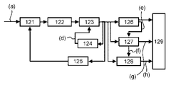
図7は、本実施形態の磁気ディスク媒体を備える磁気記録装置において、MPUが磁気ヘッドの位置決め制御を行なう際に、磁気ディスク媒体上のサーボ情報を読み取る時のリードチャネル116の動作を表わすブロック図である。図8はそのリードチャネルの動作のタイムチャートである。
FIG. 7 is a block diagram showing the operation of the read
なおサーボパターンの構成例としては、クロック同期のためのプリアンブル領域の後にサーボ信号再生の基準タイミングとなるサーボアドレスマーク(Servo Address Mark:SAM)があり、続いてセクタ番号とトラック番号を示すアドレスパターンがあり、さらにヘッドの位置を検出するためのバーストパターンがあるという構成である。 As an example of the servo pattern configuration, there is a servo address mark (Servo Address Mark: SAM) that serves as a reference timing for servo signal reproduction after the preamble area for clock synchronization, followed by an address pattern indicating the sector number and track number. In addition, there is a configuration in which there is a burst pattern for detecting the position of the head.
即ち磁気ディスク媒体1が一定角速度で回転することにより、ヘッドアンプからは一定の時間間隔でサーボパターン再生信号(a)が得られる。サーボパターン再生信号(a)はリードチャネル116内で低域通過フィルタ122によって高域ノイズ成分を遮断後、A/D変換器123によってA/D変換され、デジタル化された振幅情報を元に、ゲイン制御器125によって、最適な振幅が得られるように可変ゲイン121の調整がなされる。
That is, when the
サーボパターンの導入部は同期信号生成部21として一定周期のパターンが書かれており、位相ロックループ(PLL)回路124が収束するのに十分な波数が得られるように予めサーボゲート信号(b)がアサートされるようになっている。
The servo pattern introduction unit is written with a pattern of a fixed period as the synchronization signal generation unit 21 and the servo gate signal (b) is previously obtained so that a sufficient wave number can be obtained for the phase lock loop (PLL)
サーボゲート信号(b)がアサートされると、サーボパターン再生信号の同期信号にPLLが掛けられ、ここから、つづいてサーボパターン再生信号に現れるアドレス部および微小位置検出部をサンプリングするのに必要なADCクロック信号(d)がPLL回路124から生成される。
When the servo gate signal (b) is asserted, a PLL is applied to the synchronizing signal of the servo pattern reproduction signal, and from here, it is necessary to sample the address portion and the minute position detection portion that appear in the servo pattern reproduction signal. An ADC clock signal (d) is generated from the
サーボパターンの同期信号生成部の終端には、サーボ情報の始まりを示すサーボシンクマークパターンが、一定長のビットあるいは特定のコードパターンビットで書かれており、これを検出すると、同期パターン検出信号(c)がアサートされる。 At the end of the servo pattern synchronization signal generator, a servo sync mark pattern indicating the start of the servo information is written with a fixed length bit or a specific code pattern bit. When this is detected, the sync pattern detection signal ( c) is asserted.
同期信号検出器126が同期パターン検出信号(c)のアサートを確認して、アドレス検出ゲート信号(e)をアドレス復調器127に送ることにより、続いて再生されるアドレス部の復調が行なわれる。
The
既定長のアドレス部の復調が終了すると、アドレス復調値(g)が確定され、デジタル情報としてレジスタ129に記録される。また、つづいてバーストゲート信号(f)がアサートされ、微小位置復調器128により微小位置検出部の復調が開始される。
When the demodulation of the address portion of the predetermined length is completed, the address demodulated value (g) is determined and recorded in the
既定長の微小位置検出部の復調が終了すると、微小位置復調値(h)が確定され、デジタル情報としてレジスタ129に記録される。
以上の動作により、レジスタに格納されたアドレス復調値(g)および微小位置復調値(h)をMPU115が読み取り、磁気ヘッドの位置決め制御に必要な演算を行って、VCMドライバ112を駆動する。
When the demodulation of the predetermined position minute position detection unit is completed, the minute position demodulation value (h) is determined and recorded in the
With the above operation, the
<実施形態のポイント(1)および(2)の説明>
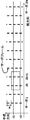
本実施形態では、半径rに接するサーボフレーム2kの内端部と、サーボフレーム2k+1の外端部を一定幅or1だけ重複させることにより、連続した半径検出を実現する。したがい、(1)ビットパターンド媒体を用いたHDD装置において、媒体上のサーボフレームを半径方向に周期Wで分断する。図1において、1周内にサーボフレームは2N箇所設置される。また(2)図1において、半径r2に存在するサーボフレーム数はN箇所であり、また、半径r1に存在するサーボフレーム数は2N箇所である。半径r1、サーボフレーム2k, 2k+1近傍を拡大した図3における、2k個目のサーボフレームと2k+1個目のサーボフレームは、半径r1において一定量or1の巾だけ重複して存在する。
<Description of Points (1) and (2) of Embodiment>
In the present embodiment, continuous radius detection is realized by overlapping the inner end portion of the
<実施形態のポイント(3)の説明>
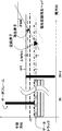
さらに、媒体上に無駄領域なくデータを記録する観点から、分断したサーボフレームの空隙部はデータ領域に供用する。すなわち、図2において、r1に接するサーボフレーム2kの内端r1-or1/2より、r1より一つ内周側の外端r1-or1/2-w+Lまでのサーボフレーム空隙部にはデータを記録する。このため、r1に接するサーボフレーム2kの内端r1-or1/2近傍にデータを記録する際においては、サーボフレーム2kの再生情報を用いることができず、サーボフレーム2k+1個の位置情報から、正確な位置決めを実施する必要がある。ここで、MR型の磁気記録再生ヘッドにおいては、再生素子と記録素子は線方向に距離をもって設置されることから、図4におけるskew角θMRのとき、半径方向に一定のMRオフセット量ΔMRr1をもつ。前述した記録時の位置決めを実現するためには、半径r1-or1/2、サーボフレーム2kの位置にデータを記録するために、サーボ2k+1は最小でも半径r1-or1/2+ΔMRr1まで存在する必要がある。これは、半径r1+or1/2まで半径方向外側へ延びているサーボフレームを読み取りつつ、隣のサーボフレームの半径方向内側のデータトラックに書き込みを行うためである。
<Description of point (3) of embodiment>
Furthermore, from the viewpoint of recording data on the medium without a waste area, the gap of the divided servo frame is used for the data area. That is, in FIG. 2, there is data in the servo frame gap from the inner end r1-or1 / 2 of the
このため本実施形態では、サーボフレーム2kおよびサーボフレーム2k+1が重複する半径r1における重複巾r1を、or1 > ΔMRr1とする。したがって、(3)図4において半径r1におけるサーボフレームの重複巾or1は半径r1におけるMRオフセット長ΔMRr1以上である。
Therefore, in the present embodiment, the overlap width r1 at the radius r1 where the
なお、半径r1の絶対量により、skew角θMRはことなることから、ΔMRr1は変化する。or1は半径に依存して変化しうる。
<実施形態のポイント(4)の説明>
図2におけるサーボフレームの半径方向の連続長Lは、サーボフレームを構成するサーボパターンに磁壁が発生しない条件から決定される。図4に、半径方向のマーク長xを意図的に変化させたサーボパターンを具備する磁気記録媒体を、磁気記録装置内で高温環境試験により加速的に磁壁を生起させ、マーク長xに対する磁壁の生起確率を測定した結果を示す。マーク長xに対する磁壁の生起確率は、磁性膜の詳細な種類あるいはサーボパターンの周方向の最大幅その他で異なるが、例えばこの媒体ではマーク長50um以下のとき、逆磁区は生起しないことが判明した。したがって、(4)ある半径のサーボフレームの半径長Lは、サーボフレームを構成するサーボパターンの磁性膜がサーボパターン内に磁壁をつくらずに単一磁区を保つことができるマーク長x_sdomain、および1.の周期W、および3.のor1と比較して、L = W/2 + or1 < x_sdomainであるよう、マーク長50umで設計した。
Note that ΔMRr1 changes because the skew angle θMR differs depending on the absolute amount of the radius r1. or1 can vary depending on the radius.
<Description of point (4) of embodiment>
The continuous length L in the radial direction of the servo frame in FIG. 2 is determined from the condition that no domain wall is generated in the servo pattern constituting the servo frame. FIG. 4 shows a magnetic recording medium having a servo pattern in which the mark length x in the radial direction is intentionally changed. A magnetic wall is accelerated in a magnetic recording apparatus by a high temperature environment test. The result of measuring the occurrence probability is shown. The occurrence probability of the domain wall with respect to the mark length x varies depending on the detailed type of the magnetic film, the maximum width in the circumferential direction of the servo pattern, and the like. . Therefore, (4) the radius length L of the servo frame having a certain radius is such that the magnetic film of the servo pattern constituting the servo frame can maintain a single magnetic domain without forming a domain wall in the servo pattern, and 1 . Cycle W, and 3. Compared with or1, the mark length is 50um so that L = W / 2 + or1 <x_sdomain.
<実施形態のポイント(5)の説明>
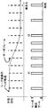
図3で示したように、サーボフレーム間の空隙に磁気記録を実現しようとしたとき、セクタサーボの処理能力あるいは再生素子への記録磁界のクロストークに起因する制約により、同一周方向位置でのデータ記録再生とサーボ信号の再生は同時に行えない。したがって、もしも周方向に2N個のサーボが現れる半径r1に位置決めを実施している際にも、記録再生時にはN個のサーボでしか位置検出ができない。対して、シーク中はサーボフレームk, およびサーボフレームk+1の空隙部をどのように通過するか事前に予測することが困難であり、サーボフレームkおよびk+1の両方がシーク中の各半径でランダムに検出されない可能性があるが、データ記録再生時のようにN個のサーボでしか位置検出ができない制約がないため、2N個のサーボすべてに対してサーボ検出を行うことでこの影響を軽減することが可能である。
<Description of point (5) of embodiment>
As shown in FIG. 3, when magnetic recording is attempted in the gap between servo frames, data at the same circumferential direction position is limited due to the processing capacity of the sector servo or restrictions caused by the crosstalk of the recording magnetic field to the reproducing element. Recording and playback and servo signal playback cannot be performed simultaneously. Therefore, even if positioning is performed at the radius r1 at which 2N servos appear in the circumferential direction, the position can be detected only by N servos during recording and reproduction. On the other hand, it is difficult to predict in advance how the servo frame k and the gap of the servo frame k + 1 pass during the seek, and both the servo frames k and k + 1 are Although it may not be detected at random by the radius, there is no restriction that only the N servos can detect the position as in the case of data recording / playback, so this effect can be obtained by performing servo detection on all 2N servos. Can be reduced.
図5において、時刻t1において記録再生を終了してシークを開始し、時刻t2においてシーク終了判定がなされたケースにおける、ヘッド軌道とサーボ検出のタイミングを図示する。時刻t1までの間、サーボは1周当たりN個の頻度で再生されている。時刻t1にシーク処理が開始されると、サーボの検出頻度は1週当たり2N個の頻度に増加し、シーク時の空隙部通過による位置検出失敗の可能性を低減する。図8のような仕組みでサーボゲート信号を発生しない場合でも、ゲートを開くタイミングを予測してこの頻度の増加は可能である。 FIG. 5 shows the head trajectory and the timing of servo detection in the case where recording / reproduction is finished at time t1 and seek is started, and seek end determination is made at time t2. Until time t1, the servo is played at a frequency of N per round. When the seek process is started at time t1, the servo detection frequency increases to a frequency of 2N per week, reducing the possibility of position detection failure due to passage of the gap during seek. Even when the servo gate signal is not generated by the mechanism as shown in FIG. 8, the frequency can be increased by predicting the opening timing of the gate.
この後に時刻t2において収束判定がなされると、サーボ検出頻度は1周当たりN個に戻り、記録再生可能な状態となる。したがって本実施形態では、(5)シーク中は、1周あたり2N箇所以上の頻度で、サーボ検出を実施する。 Thereafter, when convergence determination is made at time t2, the servo detection frequency returns to N per round, and recording and reproduction are possible. Therefore, in this embodiment, during (5) seek, servo detection is performed at a frequency of 2N or more per round.
<実施形態のポイント(1)および(2)の説明の効果>
サーボフレームを半径方向に分断することにより、サーボフレーム内の磁壁の発生およびその誤再生を未然に防止し、正常なサーボ位置検出を実現する。また、サーボフレーム分断部近傍においても、連続した半径検出を実現する。
<Effects of Explanation of Points (1) and (2) of Embodiment>
By dividing the servo frame in the radial direction, the occurrence of domain walls in the servo frame and the erroneous reproduction thereof are prevented in advance, and normal servo position detection is realized. Also, continuous radius detection is realized in the vicinity of the servo frame dividing portion.
<実施形態のポイント(3)の説明の効果>
サーボフレーム分断部の重複巾を、MRオフセット量以上とることにより、サーボフレーム空隙部へのデータ記録再生を可能とすることで、フォーマット効率を向上させ、無駄なくデータが記録できる。
<Effect of description of point (3) of embodiment>
By making the overlap width of the servo frame dividing portion equal to or greater than the MR offset amount, data recording / reproduction in the servo frame gap can be performed, thereby improving the format efficiency and recording data without waste.
<実施形態のポイント(4)の説明の効果>
磁壁の生起確率とマーク長の関係から、具体的な分断時のサーボフレームの半径長を設計し、サーボフレーム内の磁壁の発生を抑圧した。
<実施形態のポイント(5)の説明の効果>
シーク時にサーボの検出頻度を2N箇所/周とすることで、シーク時にヘッドがサーボフレーム空隙をランダムに通過することによる位置検出失敗を抑圧し、正常なシークを可能とした。
<Effect of description of point (4) of embodiment>
Based on the relationship between the occurrence probability of the domain wall and the mark length, the radius length of the servo frame at the time of the specific division was designed to suppress the occurrence of the domain wall in the servo frame.
<Effect of description of point (5) of embodiment>
By setting the servo detection frequency to 2N locations / circumference during seek, the position detection failure due to the head randomly passing through the servo frame gap during seek is suppressed, and normal seek is possible.
先行技術では、ある半径でサーボフレームが重なる(2N箇所になる)構成について開示されていない。また、サーボフレームを構成するサーボパターン内に磁壁を作らないためのサーボフレームの半径長Lの決定要件と、シーク時の制御についても開示されていない。 The prior art does not disclose a configuration in which servo frames overlap with a certain radius (2N locations). Also, there is no disclosure regarding the requirement for determining the radius length L of the servo frame so as not to create a domain wall in the servo pattern constituting the servo frame, and control during seek.
先行技術と比較し、サーボフレームを構成するサーボパターン内に磁壁が発生することによるサーボ誤読の可能性を払拭できる。本技術を用いることにより、半径方向の不連続部における非データ部の半径巾を最小でMRオフセット長の1倍にとどめることができる。 Compared with the prior art, the possibility of servo misreading due to the occurrence of domain walls in the servo pattern constituting the servo frame can be eliminated. By using this technology, the radius width of the non-data portion in the discontinuous portion in the radial direction can be kept to a minimum of one MR offset length.
ビットパターンド媒体では逆磁区の発生によりサーボ情報が劣化する。この劣化を抑圧し、かつフォーマット効率を最大限確保するための、媒体上のサーボ分断配置およびサーボ制御方法を示した。 In bit patterned media, servo information deteriorates due to the occurrence of reverse magnetic domains. In order to suppress this deterioration and to ensure the maximum format efficiency, the servo division arrangement on the medium and the servo control method were shown.
即ちビットパターンド媒体を用いた磁気記録において、実施形態は以下の特徴を有する。
(1)半径方向に不連続で、周期W毎に存在・非存在を繰り返す、2Nフレーム/周のサーボフレームを具備する。
(2)ある半径rに存在するサーボフレーム数は、Nフレーム/周ないしは2Nフレーム/周である。
(3)ある半径r1においてサーボフレームが2Nフレーム/周であったとき、半径r1における(2)の2Nフレーム/周である半径巾or1は、その半径ヘッドのリード・ライトオフセット巾ΔMRr1以上である。
That is, the embodiment has the following characteristics in magnetic recording using a bit patterned medium.
(1) Provided with 2N frames / circular servo frame that is discontinuous in the radial direction and repeats existence / non-existence every period W.
(2) The number of servo frames existing at a certain radius r is N frames / circumference or 2N frames / circumference.
(3) When the servo frame is 2N frames / periphery at a certain radius r1, the radius width or1 which is 2N frames / periphery of (2) at the radius r1 is equal to or larger than the read / write offset width ΔMRr1 of the radius head. .
(4)ある半径のサーボフレームの半径長Lは、サーボフレームを構成するサーボパターンの磁性膜がサーボパターン内に磁壁をつくらずに単一磁区を保つことができるマーク長x_sdomain、および(1)の周期W、および(3)のor1と比較して、L = W/2 + or1 < x_sdomainである。 (4) The radius length L of the servo frame having a certain radius is a mark length x_sdomain that allows the magnetic film of the servo pattern constituting the servo frame to maintain a single magnetic domain without forming a domain wall in the servo pattern, and (1) L = W / 2 + or1 <x_sdomain compared to the period W of (3) and or1 of (3).
(5)シーク中は、1周あたり2N箇所以上の頻度で、サーボ検出を実施する。
なお、この発明は上記実施形態に限定されるものではなく、この外その要旨を逸脱しない範囲で種々変形して実施することができる。
また、上記した実施の形態に開示されている複数の構成要素を適宜に組み合わせることにより、種々の発明を形成することができる。例えば、実施の形態に示される全構成要素から幾つかの構成要素を削除しても良いものである。さらに、異なる実施の形態に係わる構成要素を適宜組み合わせても良いものである。
(5) During seek, servo detection is performed at a frequency of 2N or more per lap.
In addition, this invention is not limited to the said embodiment, In the range which does not deviate from the summary, it can implement in various modifications.
Various inventions can be formed by appropriately combining a plurality of constituent elements disclosed in the above-described embodiments. For example, some components may be deleted from all the components shown in the embodiment. Furthermore, constituent elements according to different embodiments may be appropriately combined.
1 磁気ディスク媒体
101 ディスクエンクロージャ
102 スピンドルモータ
103 磁気ヘッド
105 ボイス・コイル・モータ
106 キャリッジアーム
107 ヘッドアンプ
108 ヘッドジンバル組立体
110 シャフト
111 スピンドルモータドライバ
112 ボイス・コイル・モータドライバ
113 記録信号
114 再生信号
115 マイクロ・プロセッシング・ユニット
116 リードチャネル
117 ディスクコントローラ
118 ホストコンピュータ
DESCRIPTION OF
Claims (5)
前記第1磁性ドットの位置を特定するための複数の第2磁性ドットを所定の位置に配置したサーボ領域とを表面に備え、
このサーボ領域中に径方向に不連続で、周期W毎に存在・非存在を繰り返す、2Nフレーム/周のサーボフレームを具備して成る磁気記録媒体。 A data area in which a plurality of first magnetic dots are arranged at predetermined positions to record information;
A servo area in which a plurality of second magnetic dots for specifying the positions of the first magnetic dots are arranged at predetermined positions on the surface;
A magnetic recording medium comprising a servo frame of 2N frames / circumference that is discontinuous in the radial direction in this servo area and repeats existence / non-existence every period W.
前記第1磁性ドットの位置を特定するための複数の第2磁性ドットを所定の位置に配置したサーボ領域とを表面に備え、
このサーボ領域中に径方向に不連続で、周期W毎に存在・非存在を繰り返す、2Nフレーム/周のサーボフレームを具備して成る磁気記録媒体と、
前記磁気記録媒体へ磁気情報を記録する又は前記磁気記録媒体の磁気情報を再生するために前記磁気記録媒体の表面に対向するように配置された素子を有する磁気ヘッドと
を備える磁気記録装置。 A data area in which a plurality of first magnetic dots are arranged at predetermined positions to record information;
A servo area in which a plurality of second magnetic dots for specifying the positions of the first magnetic dots are arranged at predetermined positions on the surface;
A magnetic recording medium comprising a servo frame of 2N frames / circumference that is discontinuous in the radial direction in this servo area and repeats existence / non-existence every period W;
A magnetic recording apparatus comprising: a magnetic head having an element disposed so as to face the surface of the magnetic recording medium for recording magnetic information on the magnetic recording medium or reproducing magnetic information of the magnetic recording medium.
Priority Applications (2)
| Application Number | Priority Date | Filing Date | Title |
|---|---|---|---|
| JP2011120940A JP2012248254A (en) | 2011-05-30 | 2011-05-30 | Magnetic recording medium and magnetic recorder |
| US13/372,367 US8842392B2 (en) | 2011-05-30 | 2012-02-13 | Magnetic recording medium and magnetic recording apparatus |
Applications Claiming Priority (1)
| Application Number | Priority Date | Filing Date | Title |
|---|---|---|---|
| JP2011120940A JP2012248254A (en) | 2011-05-30 | 2011-05-30 | Magnetic recording medium and magnetic recorder |
Publications (1)
| Publication Number | Publication Date |
|---|---|
| JP2012248254A true JP2012248254A (en) | 2012-12-13 |
Family
ID=47261527
Family Applications (1)
| Application Number | Title | Priority Date | Filing Date |
|---|---|---|---|
| JP2011120940A Pending JP2012248254A (en) | 2011-05-30 | 2011-05-30 | Magnetic recording medium and magnetic recorder |
Country Status (2)
| Country | Link |
|---|---|
| US (1) | US8842392B2 (en) |
| JP (1) | JP2012248254A (en) |
Citations (4)
| Publication number | Priority date | Publication date | Assignee | Title |
|---|---|---|---|---|
| JP2000195200A (en) * | 1998-12-24 | 2000-07-14 | Toshiba Corp | Magnetic disk device |
| JP2001028111A (en) * | 1999-07-13 | 2001-01-30 | Hitachi Ltd | Magnetic disk device |
| JP2006260741A (en) * | 2005-02-16 | 2006-09-28 | Tdk Corp | Magnetic recording medium, recording and reproducing apparatus, and stamper |
| JP2007257733A (en) * | 2006-03-23 | 2007-10-04 | Fujitsu Ltd | Eccentricity correction method, signal processing circuit, magnetic storage device, and perpendicular magnetic recording medium |
Family Cites Families (9)
| Publication number | Priority date | Publication date | Assignee | Title |
|---|---|---|---|---|
| US5073833A (en) | 1989-11-13 | 1991-12-17 | International Business Machines Corporation | Dual sector servo system for disk file with separate read and write heads |
| JP2936770B2 (en) | 1991-03-28 | 1999-08-23 | 日本電気株式会社 | Semiconductor light receiving element |
| JPH06111502A (en) * | 1992-09-30 | 1994-04-22 | Sony Corp | Magnetic disk device |
| JP3787491B2 (en) * | 2000-11-20 | 2006-06-21 | 株式会社日立グローバルストレージテクノロジーズ | Magnetic disk unit |
| JP4209231B2 (en) * | 2003-03-26 | 2009-01-14 | Tdk株式会社 | Magnetic recording medium and method for manufacturing magnetic recording medium |
| JP4015123B2 (en) | 2004-02-25 | 2007-11-28 | 株式会社東芝 | Disk device, servo pattern writing method |
| JP2005276352A (en) * | 2004-03-25 | 2005-10-06 | Fuji Photo Film Co Ltd | Magnetic recording medium, its manufacturing method, magnetic transfer patterned master carrier used for the manufacturing method, and magnetic recording/reproducing device |
| JP4585268B2 (en) * | 2004-10-15 | 2010-11-24 | 東芝ストレージデバイス株式会社 | Information storage device, control method, and program |
| CN100416653C (en) | 2005-02-16 | 2008-09-03 | Tdk股份有限公司 | Magnetic recording medium, recording/reproducing apparatus, and stamper |
-
2011
- 2011-05-30 JP JP2011120940A patent/JP2012248254A/en active Pending
-
2012
- 2012-02-13 US US13/372,367 patent/US8842392B2/en not_active Expired - Fee Related
Patent Citations (4)
| Publication number | Priority date | Publication date | Assignee | Title |
|---|---|---|---|---|
| JP2000195200A (en) * | 1998-12-24 | 2000-07-14 | Toshiba Corp | Magnetic disk device |
| JP2001028111A (en) * | 1999-07-13 | 2001-01-30 | Hitachi Ltd | Magnetic disk device |
| JP2006260741A (en) * | 2005-02-16 | 2006-09-28 | Tdk Corp | Magnetic recording medium, recording and reproducing apparatus, and stamper |
| JP2007257733A (en) * | 2006-03-23 | 2007-10-04 | Fujitsu Ltd | Eccentricity correction method, signal processing circuit, magnetic storage device, and perpendicular magnetic recording medium |
Also Published As
| Publication number | Publication date |
|---|---|
| US8842392B2 (en) | 2014-09-23 |
| US20120307403A1 (en) | 2012-12-06 |
Similar Documents
| Publication | Publication Date | Title |
|---|---|---|
| US7075746B1 (en) | Disk drives and disk drive containing devices that include a servo frequency generator and spindle control timer that compensate for disk eccentricity | |
| US7474493B2 (en) | Alternative DC-burst servo pattern for perpendicular recording | |
| JP2008243266A (en) | Magnetic recording medium, servo recording method to magnetic recording medium and magnetic recording device | |
| US8107180B2 (en) | Hard-disk drive and control method for magnetic recording on a patterned medium of the hard-disk drive | |
| JP2010140565A (en) | Magnetic recording/reproducing apparatus | |
| JP5049910B2 (en) | Magnetic storage medium and magnetic recording apparatus | |
| US7365933B2 (en) | Servo information recording method, magnetic recording media, and magnetic disk apparatus | |
| US8488264B2 (en) | Magnetic disk device, signal processing circuit, and signal processing method | |
| US20030099050A1 (en) | Apparatus and method for writing head positioning information to disk medium | |
| JP2003228927A (en) | Magnetic disk device magnetic recording medium, and servo write system | |
| JP4331236B2 (en) | Disk storage | |
| JP2012248254A (en) | Magnetic recording medium and magnetic recorder | |
| US7729078B2 (en) | Information storage device | |
| JP2006164448A (en) | Disk device and its control method | |
| JP2007293930A (en) | Method for writing servo pattern on recording surface and data storage device | |
| US6999259B2 (en) | Master disc and method of manufacturing the same | |
| KR100723499B1 (en) | Method for generating servo write clock of hard disc drive and recording medium for the same | |
| JP2006048920A (en) | Magnetic recording medium | |
| JP2008065935A (en) | Disk recording medium and information recording device | |
| JP2009181657A (en) | Magnetic recording device and clock signal generating method | |
| JP2006277875A (en) | Head position computing method in magnetic disk device | |
| JP2012128896A (en) | Magnetic recording medium and magnetic recorder | |
| US20120229929A1 (en) | Magnetic recording medium and magnetic reading apparatus | |
| JP2004288342A (en) | Magnetic disk device and servo signal writing method | |
| JP2006228348A (en) | Information writing device and method, magnetic disk manufacturing device and method, and magnetic disk |
Legal Events
| Date | Code | Title | Description |
|---|---|---|---|
| A621 | Written request for application examination |
Free format text: JAPANESE INTERMEDIATE CODE: A621 Effective date: 20130830 |
|
| A131 | Notification of reasons for refusal |
Free format text: JAPANESE INTERMEDIATE CODE: A131 Effective date: 20140627 |
|
| A02 | Decision of refusal |
Free format text: JAPANESE INTERMEDIATE CODE: A02 Effective date: 20141024 |