JP2012247936A - Information processor, display control method and program - Google Patents
Information processor, display control method and program Download PDFInfo
- Publication number
- JP2012247936A JP2012247936A JP2011118319A JP2011118319A JP2012247936A JP 2012247936 A JP2012247936 A JP 2012247936A JP 2011118319 A JP2011118319 A JP 2011118319A JP 2011118319 A JP2011118319 A JP 2011118319A JP 2012247936 A JP2012247936 A JP 2012247936A
- Authority
- JP
- Japan
- Prior art keywords
- hover
- inclination
- offset value
- device body
- display control
- Prior art date
- Legal status (The legal status is an assumption and is not a legal conclusion. Google has not performed a legal analysis and makes no representation as to the accuracy of the status listed.)
- Withdrawn
Links
Images


Classifications
-
- G—PHYSICS
- G06—COMPUTING; CALCULATING OR COUNTING
- G06F—ELECTRIC DIGITAL DATA PROCESSING
- G06F3/00—Input arrangements for transferring data to be processed into a form capable of being handled by the computer; Output arrangements for transferring data from processing unit to output unit, e.g. interface arrangements
- G06F3/01—Input arrangements or combined input and output arrangements for interaction between user and computer
- G06F3/048—Interaction techniques based on graphical user interfaces [GUI]
- G06F3/0487—Interaction techniques based on graphical user interfaces [GUI] using specific features provided by the input device, e.g. functions controlled by the rotation of a mouse with dual sensing arrangements, or of the nature of the input device, e.g. tap gestures based on pressure sensed by a digitiser
- G06F3/0488—Interaction techniques based on graphical user interfaces [GUI] using specific features provided by the input device, e.g. functions controlled by the rotation of a mouse with dual sensing arrangements, or of the nature of the input device, e.g. tap gestures based on pressure sensed by a digitiser using a touch-screen or digitiser, e.g. input of commands through traced gestures
-
- G—PHYSICS
- G06—COMPUTING; CALCULATING OR COUNTING
- G06F—ELECTRIC DIGITAL DATA PROCESSING
- G06F2200/00—Indexing scheme relating to G06F1/04 - G06F1/32
- G06F2200/16—Indexing scheme relating to G06F1/16 - G06F1/18
- G06F2200/163—Indexing scheme relating to constructional details of the computer
- G06F2200/1637—Sensing arrangement for detection of housing movement or orientation, e.g. for controlling scrolling or cursor movement on the display of an handheld computer
-
- G—PHYSICS
- G06—COMPUTING; CALCULATING OR COUNTING
- G06F—ELECTRIC DIGITAL DATA PROCESSING
- G06F2203/00—Indexing scheme relating to G06F3/00 - G06F3/048
- G06F2203/041—Indexing scheme relating to G06F3/041 - G06F3/045
- G06F2203/04101—2.5D-digitiser, i.e. digitiser detecting the X/Y position of the input means, finger or stylus, also when it does not touch, but is proximate to the digitiser's interaction surface and also measures the distance of the input means within a short range in the Z direction, possibly with a separate measurement setup
Abstract
Description
本開示は、情報処理装置、表示制御方法及びプログラムに関する。 The present disclosure relates to an information processing apparatus, a display control method, and a program.
指やスタイラス等を使ってタッチパネルの操作を行う場合、機器本体に付設された特定の操作キー又はタッチパネル上に設けられた特定の操作領域を使って入力操作のモード変更を行うことができる。通常の入力操作モードでは、タッチ直後にリリースを行う操作が、マウス操作時における通常のクリックに相当する。マウス操作には、前記クリック以外にマウスポインタのみの移動操作が挙げられ、ユーザは状況に応じてこれらの操作を使い分けることが必要とされる。マウスポインタの移動操作に相当するモードをホバーモード、マウスポインタの移動操作のための表示をホバー表示という。 When the operation of the touch panel is performed using a finger, a stylus, or the like, the mode of the input operation can be changed using a specific operation key attached to the device main body or a specific operation area provided on the touch panel. In the normal input operation mode, an operation of releasing immediately after touching corresponds to a normal click during mouse operation. The mouse operation includes a movement operation using only the mouse pointer in addition to the click, and the user is required to use these operations properly depending on the situation. A mode corresponding to a mouse pointer movement operation is called a hover mode, and a display for moving the mouse pointer is called a hover display.
指などがタッチ面に触れないまでも、ある程度までタッチ面に近づいた場合、タッチ面から指までの対向距離に応じた表示状態の変化が起これば、今までにない情報表示状態を実現できる。例えば、指がタッチ面に接触した場合には入力操作モード、指が所定距離だけタッチ面に近接した場合にはホバーモードというように遷移して、表示状態のモードの変更が行われる構成形態では、占有面積を最小限に抑えて多種の操作を行うことができる。 Even if a finger or the like does not touch the touch surface, if the display state changes according to the facing distance from the touch surface to the finger when it approaches the touch surface to some extent, an unprecedented information display state can be realized . For example, when the finger touches the touch surface, the input operation mode is changed, and when the finger comes close to the touch surface by a predetermined distance, the transition is made to the hover mode, and the display mode is changed. Various operations can be performed while minimizing the occupied area.
例えば、特許文献1では、静電容量型の表示パネルを用いて、表示パネルのタッチ面に指先が接触したときに接触した指先の位置を検出するとともに、タッチ面に指先が近づいたときに近接した指先の位置を検出する技術が提案されている。
For example, in
しかしながら、ホバー表示されている対象(ホバー対象)に指を近付けていくと、ホバー対象に向けられている視線が操作する指で遮られ、ホバー対象の文字等が指で隠れて指の操作が正しくホバー対象に反応しているか見分けることが難しくなる。 However, as you move your finger closer to the hover target (hover target), the line of sight directed at the hover target is blocked by the finger you are operating, and the hover target character is hidden by your finger so that you can operate your finger. It becomes difficult to tell if it is responding correctly to the hover target.
そこで、ホバー対象が指で隠れないようにホバー座標のオフセットを最適化することが求められていた。 Therefore, it has been required to optimize the offset of the hover coordinates so that the hover target is not hidden by the finger.
本開示によれば、タッチパネルのタッチ面に表示されたホバー座標とデバイス本体の傾きとを特定し、前記特定されたデバイス本体の傾きに応じて前記特定されたホバー座標のオフセット値を決定する表示制御部を備える、情報処理装置が提供される。 According to the present disclosure, the hover coordinates displayed on the touch surface of the touch panel and the inclination of the device main body are specified, and the offset value of the specified hover coordinates is determined according to the specified inclination of the device main body. An information processing apparatus including a control unit is provided.
また、本開示によれば、タッチパネルのタッチ面に表示されたホバー座標を特定することと、デバイス本体の傾きを特定することと、前記特定されたデバイス本体の傾きに応じて前記特定されたホバー座標のオフセット値を決定することを含む、表示制御方法が提供される。 Further, according to the present disclosure, the hover coordinates displayed on the touch surface of the touch panel are specified, the inclination of the device body is specified, and the specified hover is determined according to the specified inclination of the device body. A display control method is provided that includes determining a coordinate offset value.
また、本開示によれば、タッチパネルのタッチ面に表示されたホバー座標を特定する処理と、デバイス本体の傾きを特定する処理と、前記特定されたデバイス本体の傾きに応じて前記特定されたホバー座標のオフセット値を決定する処理と、をコンピュータに実行させるためのプログラムが提供される。 In addition, according to the present disclosure, the process for identifying the hover coordinates displayed on the touch surface of the touch panel, the process for identifying the tilt of the device body, and the identified hover according to the tilt of the identified device body A program for causing a computer to execute a process for determining an offset value of coordinates is provided.
以上説明したように本開示によれば、ホバー対象が指で隠れないようにホバー座標のオフセットを最適化することができる。 As described above, according to the present disclosure, the offset of the hover coordinates can be optimized so that the hover target is not hidden by the finger.
以下に添付図面を参照しながら、本開示の好適な実施の形態について詳細に説明する。なお、本明細書及び図面において、実質的に同一の機能構成を有する構成要素については、同一の符号を付することにより重複説明を省略する。 Hereinafter, preferred embodiments of the present disclosure will be described in detail with reference to the accompanying drawings. In addition, in this specification and drawing, about the component which has the substantially same function structure, duplication description is abbreviate | omitted by attaching | subjecting the same code | symbol.
なお、説明は以下の順序で行うものとする。
1.ファットフィンガ
2.第1実施形態(デバイス本体の傾きとオフセット)
3.第2実施形態(デバイス本体の傾き及び視線の傾きの差分とオフセット)
4.第3実施形態(オフセット値の正負判定)
The description will be made in the following order.
1. Fat finger First Embodiment (Inclination and Offset of Device Body)
3. Second embodiment (difference and offset of device body tilt and line-of-sight tilt)
4). Third embodiment (offset value positive / negative determination)
<1.ファットフィンガ>
まず、ファットフィンガについて説明する。ここでは、ホバー表示の一例としてホバーカーソルを例に挙げて説明するが、ホバー表示の方法はどんな図形や画像を用いてもよい。
<1. Fat Finger>
First, the fat finger will be described. Here, a hover cursor will be described as an example of hover display, but any figure or image may be used as the hover display method.
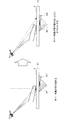
図3の左方に示したように、指が情報処理装置の筐体であるデバイス本体11上のタッチ面Tに対して所定時間以上近接状態にあるときホバーモードに遷移し、ホバーカーソルH1がホバー表示される。ホバーカーソルH1は、入力操作対象の位置を指し示す図形である。指が近接状態のままタッチ面Tの上方を移動すると、ホバーカーソルH1が移動し、指がホバーカーソルH1をタッチすると、ホバーカーソルH1内の文字等が入力操作される。
As shown on the left side of FIG. 3, when the finger is in a proximity state for a predetermined time or more with respect to the touch surface T on the device
しかし、ホバーカーソルH1に指を近付けていく際、ホバー対象に向けられている視線が操作する指で遮られ、ホバー対象の文字等が指で隠れて指の操作がホバー対象に正しく反応しているか見分けることが難しくなる。これをファットフィンガ(Fat Finger)という。 However, when the finger is brought close to the hover cursor H1, the line of sight directed toward the hover target is blocked by the operated finger, the hover target character is hidden by the finger, and the finger operation reacts correctly to the hover target. It becomes difficult to tell if it is. This is called a fat finger.
そこで、ホバー対象に向けられている視線が操作する指で隠れないように、ホバーカーソルH1の位置を示すホバー座標をわずかにオフセットし、オフセット後のホバー座標にホバーカーソルH1’を表示する。図3の右方では、ホバー対象に向けられている視線が操作する指で遮られない位置までホバーカーソルH1’が移動している。これにより、指がホバー対象に正しく反応しているかを見分けることが容易になる。 Therefore, the hover coordinates indicating the position of the hover cursor H1 are slightly offset so that the line of sight directed toward the hover target is not hidden by the operated finger, and the hover cursor H1 'is displayed at the hover coordinates after the offset. On the right side of FIG. 3, the hover cursor H <b> 1 ′ has moved to a position where the line of sight directed toward the hover target is not blocked by the operated finger. This makes it easy to tell if the finger is responding correctly to the hover target.
ところが、図4の左方に示したように、デバイス本体11の傾きが0度の場合のホバー座標のオフセット値と、図4の右方に示したように、デバイス本体11の傾きが45度の場合のホバー座標のオフセット値とを同値に設定すると、デバイス本体11の傾きが45度の場合には、オフセット後のホバー座標に表示したホバーカーソルH1’が、逆に指から離れすぎて「ズレ」としてユーザに認識されてしまう場合がある。
However, as shown on the left side of FIG. 4, the offset value of the hover coordinates when the inclination of the
<2.第1実施形態>
そこで、第1実施形態に係る情報処理装置10では、デバイス本体11の傾きに応じてホバー座標のオフセット値を可変に制御し、これにより、適切な位置にホバーカーソルを表示する。情報処理装置10は、ユーザの指の接触位置、近接位置及びデバイス本体の傾きを検出できるセンサを搭載したデバイスである。情報処理装置10は、近接式タッチパネル付きの機器であればよい。
<2. First Embodiment>
Therefore, in the
(ハードウエア構成)
図1は、第1実施形態に係る情報処理装置10のハードウエア構成を示す。第1実施形態に係る情報処理装置10は、近接検出式タッチパネル12、傾き検出センサ14、視線検出センサ16、CPU18、RAM20、不揮発メモリ22及び表示装置24を有する。
(Hardware configuration)
FIG. 1 shows a hardware configuration of an
近接検出式タッチパネル12は、近接を検出可能な表示パネルである。近接検出式タッチパネル12には静電容量式の表示パネルが用いられる。たとえば、図2に示したように、指から近接検出式タッチパネル12のタッチ面までの距離が予め定められた閾値Lpより大きい場合、近接検出式タッチパネル12は何も検知しない(図2(a):非近接状態 不感帯)。指からタッチ面までの距離が閾値Lpより小さくなり指が中間検出領域に入り所定時間が経過すると、近接検出式タッチパネル12は指の近接位置を検出する(図2(b):近接状態 感帯)。指がタッチ面に接触した場合、近接検出式タッチパネル12は指の接触位置を検出する(図2(c):接触状態)。
The proximity
このように、近接検出式タッチパネル12は、近接検出式タッチパネル12のタッチ面からの奥行き方向(z方向の座標)の指の近接位置を検出するとともに、タッチ面での指の接触位置(x方向及びy方向の座標)を検出することが可能である。
As described above, the proximity detection
再び図1に戻って、傾き検出センサ14は、情報処理装置10のデバイス本体11に取り付けられていて、デバイス本体11の基本姿勢(デバイス本体11の傾き0度)の基準面に対するx軸方向及びy軸方向の傾斜角を算出する。傾き検出センサ14は、加速度センサの一例としてのジャイロセンサで実現することができる。
Returning to FIG. 1 again, the
視線検出センサ16は、近接検出式タッチパネル12を操作するユーザの視線を検出する。例えば、視線検出センサ16は、視線検出方法を用いて瞳孔の動きをカメラで追跡し、撮像した画像を解析することにより視線の傾き(視線の方向)を検出する。光学式センサを用いて画像から虹彩、瞳孔、ブルキニエ像(反射像)を検出することにより視線の傾きを検出してもよい。
The line-of-
近接検出式タッチパネル12、傾き検出センサ14、視線検出センサ16によりそれぞれ検出されたセンサ値は、RAM20又は不揮発性メモリ22に送られ、記憶される。CPU18は各部と接続されていて、RAM20又は不揮発性メモリ22に記憶された各種センサ値を取得し、各種センサ値に基づき、指の接触位置、指の近接位置、デバイス本体の傾き、視線の傾きを算出する。
The sensor values detected by the proximity
また、RAM20や不揮発メモリ22には、ホバー座標のオフセット処理を実行するためのプログラムやオフセット値を決定するためのテーブル、閾値等の各種データが記憶されている。CPU18は、上記プログラムを読み出して実行することにより、ホバー座標のオフセット処理を実行する。表示装置24は、オフセット処理後のホバー座標の位置にホバーカーソル等を表示する。CPU18は、表示装置24と接続され、表示装置24から送信される情報を処理する。
The
(機能構成)
以上、図1を参照して、第1実施形態に係る情報処理装置10のハードウエア構成を説明した。次に、図5を参照しながら、第1実施形態に係る情報処理装置10の機能構成について説明する。第1実施形態に係る情報処理装置10は、表示制御部30と記憶部32とを有している。
(Functional configuration)
The hardware configuration of the
表示制御部30は、近接検出式タッチパネル12によるホバー座標の検出結果から近接検出式タッチパネル12のタッチ面に表示されたホバー座標(x方向、y方向の座標)を特定する。表示制御部30は、近接検出式タッチパネル12による奥行き検出結果から指の近接位置(z方向の座標)を特定する。表示制御部30は、傾き検出センサ14によるデバイス本体11の傾き検出結果からデバイス本体11の傾きを特定する。表示制御部30は、特定されたデバイス本体11の傾きに応じて、ホバー座標のオフセット値を決定してもよい。また、表示制御部30は、視線検出センサ16による視線検出結果からタッチ面への視線の傾きを特定する。表示制御部30は、デバイス本体の傾き及び視線の傾きの差分に応じてオフセット値を決定してもよい。表示制御部30は、オフセット値をホバー座標に加算することによりホバー座標を補正し、これによりタッチ面のホバー表示をずらす。
The
記憶部32は、近接又は非近接を判定するための閾値Lpや、オフセット値を決定するためのテーブル(図7、図13)を記憶する。表示制御部30は、各テーブルに基づき、オフセット値を決定することができる。
The
(動作)
以上、図5を参照して、第1実施形態に係る情報処理装置10の機能構成を説明した。続いて、図6〜図9を参照し、第1実施形態に係る情報処理装置10の動作を説明する。
(Operation)
The functional configuration of the
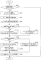
図6は、第1実施形態に係る情報処理装置10の動作を示すフローチャートである。図6に示したように、まず、指が中空検出領域内で一定時間待機していることが検出された場合(S605)、表示制御部30は、ホバーモードに遷移し、表示装置24にホバーカーソルを表示させる(S610)。
FIG. 6 is a flowchart showing the operation of the
また、表示制御部30は、近接検出式タッチパネル12からホバー座標の検出結果を取得し(S615)、傾き検出センサ14からデバイス本体11の傾き検出結果を取得する(S620)。続いて、表示制御部30は、デバイス本体11の傾きに応じて、ホバーカーソルのオフセット値を決定する(S625)。ここで、図7を参照し、デバイス本体の傾きとオフセット値との関係について具体的に説明する。
Further, the
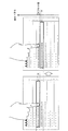
図7は、デバイス本体の傾きとオフセット値との関係を示したテーブルである。図7に示したように、例えばデバイス本体11の傾きが0〜90度の範囲内では傾きが大きいほどオフセット値は減少する。また、デバイス本体11の傾きが90〜180度の範囲内ではオフセット値は0となる。
FIG. 7 is a table showing the relationship between the tilt of the device body and the offset value. As shown in FIG. 7, for example, when the inclination of the
デバイス本体11の傾きが180〜270度の範囲内では傾きが大きいほどオフセット値は増加する。さらに、表示制御部30は、デバイス本体11の傾きが270〜360度の範囲内ではオフセット値は一定になり、デバイス本体11の傾きが0度の場合と同値になる。このテーブルでは、いずれの範囲内でもオフセット値は正の値をもつ。
When the inclination of the
ここで、図6に戻ると、表示制御部30は、S625において決定したオフセット値を、S615において取得したホバー座標に加算する(S630)。そして、表示制御部30は、S630で算出したホバー座標にホバーカーソルを表示するように制御する(S635)。以上、情報処理装置10の動作について説明した。以下、図8および図9を参照し、ホバーカーソルの表示制御についてより具体的に説明する。
Here, returning to FIG. 6, the
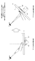
図8は、デバイス本体11の代表的な傾きにおいてホバー座標に加算されるオフセット値を説明するための図である。図8に示したように、ホバー座標に加算されるオフセット値は、デバイス本体11の傾きが0度の場合に最も大きく、デバイス本体11の傾きが90度の場合に最も小さくなる。デバイス本体11の傾きが45度の場合のオフセット値は、傾きが0度の場合のオフセット値と90度の場合のオフセット値の中間値をとる。これにより、デバイス本体11の傾きに応じて、ホバーカーソルHで示された文字等が指で隠れてしまうことを防止しつつ、適切な位置にホバーカーソルHを表示することが可能となる。
FIG. 8 is a diagram for explaining an offset value to be added to the hover coordinates in a typical inclination of the
図9は、ホバー表示例である。ホバー座標にオフセット値を加算しないと、図9の左方に示したように、ホバーカーソルHで示されるホバー対象の文字等が指で隠れてしまう。一方、本実施形態では、デバイス本体の傾きに応じて、オフセット値を可変に制御することにより、図9の右方に示したようにホバーカーソルHで示されるホバー対象の文字等が指で隠れず、かつホバーカーソルHが指から離れすぎないようにホバー表示を制御することができる。これにより、デバイス本体11の傾きによってユーザの操作コンテキストを推定し、ホバー表示時のオフセット値を最適値に調整することによって、指の操作がホバー対象に正しく反応しているかを見分けることが容易になる。
FIG. 9 is an example of hover display. If the offset value is not added to the hover coordinates, the hover target character or the like indicated by the hover cursor H is hidden with a finger as shown on the left side of FIG. On the other hand, in this embodiment, by controlling the offset value variably according to the tilt of the device body, the character or the like to be hovered indicated by the hover cursor H is hidden with a finger as shown on the right side of FIG. And hover display can be controlled so that the hover cursor H is not too far from the finger. Thereby, it is easy to identify whether the finger operation is correctly responding to the hover target by estimating the operation context of the user based on the inclination of the
(変形例)
以上、第1実施形態に係る情報処理装置10では、デバイス本体11の傾きに応じてオフセット値を可変に制御した。これに対して、変形例では視線の傾きに応じてオフセット値を可変に制御する。図10を参照しながら変形例について説明する。
(Modification)
As described above, in the
図10は、視線の代表的な傾きにおいてホバー座標に加算されるオフセット値を示す。図10に示したように、ホバー座標に加算されるオフセット値は、視線の傾きが135度及び45度の場合、正負が反対で大きさが同じ値を有し、視線の傾きが90度の場合は視線方向の傾きが135度と45度の場合より小さい値をとってもよい。これにより、視線の傾きに応じて、ホバーカーソルH内の文字等が指で隠れてしまうことを防止しつつ、適切な位置にホバーカーソルHを表示することが可能となる。 FIG. 10 shows an offset value added to the hover coordinates at a representative inclination of the line of sight. As shown in FIG. 10, the offset value added to the hover coordinates has the same value with the opposite magnitude when the line-of-sight inclination is 135 degrees and 45 degrees, and the line-of-sight inclination is 90 degrees. In such a case, a smaller value may be taken when the inclination in the line-of-sight direction is 135 degrees and 45 degrees. Accordingly, it is possible to display the hover cursor H at an appropriate position while preventing the characters in the hover cursor H from being hidden by a finger according to the inclination of the line of sight.
<3.第2実施形態>
次に、第2実施形態に係る情報処理装置10について説明する。第2実施形態に係る情報処理装置10のハードウエア構成及び機能構成は第1実施形態と同じであるため、ここでは省略する。以下では、図11〜図13を参照し、第2実施形態に係る情報処理装置10の動作について説明する。
<3. Second Embodiment>
Next, the
(動作)
図11は、第2実施形態に係る情報処理装置10の動作を示すフローチャートである。S605〜S620は第1実施形態と同様であり、指が中空検出領域内で一定時間待機していることが検出された場合(S605)、表示制御部30は、ホバーモードに遷移し、表示装置24にホバーカーソルを表示させる(S610)。また、表示制御部30は、近接検出式タッチパネル12からホバー座標の検出結果を取得し(S615)、傾き検出センサ14からデバイス本体11の傾き検出結果を取得する(S620)。
(Operation)
FIG. 11 is a flowchart showing the operation of the
次に、表示制御部30は、視線検出センサ16から視線の傾きの検出結果を取得したかを判定する(S1105)。取得したと判定した場合、表示制御部30は、デバイス本体11の傾きと視線の傾きの差分に基づき、オフセット値を決定する(S1110)。ここで、図12を参照し、デバイス本体11の傾きと視線の傾きの差分(以下、単に差分ともいう)とオフセット値との関係について具体的に説明する。
Next, the
図12の中央に示すグラフは、デバイス本体11の傾きと視線の傾きの差分とオフセット値との関係を示したテーブルである。図12に示したように、例えばデバイス本体11の傾きと視線の傾きの差分が0〜90度の範囲内では、前記差分が大きいほどオフセット値は増加する。また、この範囲でのオフセット値は負の値を取る。デバイス本体11の傾きと視線の傾きの差分が90〜180度の範囲内でも、前記差分が大きいほどオフセット値は増加する。また、この範囲でのオフセット値は正の値を取る。
The graph shown in the center of FIG. 12 is a table showing the relationship between the difference between the inclination of the device
デバイス本体11の傾きと視線の傾きの差分が180〜360度の範囲内ではその差分の値によらずオフセット値は0となる。180〜360度の範囲内では、タッチ面の裏側から覗く形になるためオフセット処理は不要だからである。
When the difference between the inclination of the device
ここで、図11の説明に戻り、S1105において視線検出センサ16から視線の傾きの検出結果を取得していないと判定した場合、表示制御部30は、デバイス本体11の傾きに応じてオフセット値を決定する(S625)。
Here, returning to the description of FIG. 11, if it is determined in S <b> 1105 that the detection result of the visual line inclination is not acquired from the visual
次に、表示制御部30は、S1110又はS625において決定したオフセット値を、S615において検出したホバー座標に加算する(S630)。そして、表示制御部30は、S630で算出したオフセット後のホバー座標にホバーカーソルを表示するように制御する(S635)。以下、図12および図13を参照し、ホバーカーソルの表示制御についてより具体的に説明する。
Next, the
図12の右方及び左方は、デバイス本体11の傾きと視線の傾きとの差分が45度と135度の場合のオフセット値を示す。前記差分が45度の場合にホバー座標に加算されるオフセット値は、差分が135度の場合にホバー座標に加算されるオフセット値と正負が逆で絶対値が同じ値となる。これにより、デバイス本体11の傾きと視線の傾きとの差分に応じて、ホバーカーソルHで示されたホバー対象の文字等が指で隠れてしまうことを防止しつつ、適切な位置にホバーカーソルHを表示することが可能となる。
The right side and the left side of FIG. 12 show offset values when the difference between the inclination of the
図9及び図13は、ホバー表示例である。前述したように、ホバー座標にオフセット値を加算しないと、図9及び図13の左方で示したように、ホバーカーソルHで示されるホバー対象の文字等が指で隠れてしまう。S1105本実施形態では、デバイス本体11の傾きと視線の傾きの差分に応じてオフセット値を可変に制御することにより、図9及び図13の右方に示したようにホバーカーソルHで示されるホバー対象の文字等が指で隠れず、かつホバーカーソルHが指から離れすぎないようにホバー表示を制御することができる。この結果、指の操作がホバーに正しく反応しているか見分けることが容易になる。
9 and 13 are examples of hover display. As described above, if the offset value is not added to the hover coordinates, the hover target character or the like indicated by the hover cursor H is hidden with a finger as shown on the left side of FIGS. S1105 In the present embodiment, the offset value is variably controlled according to the difference between the tilt of the
また、オフセット値が負の値となる場合には、図13の右方に示したようにホバーカーソルHの位置は、オフセット値が正の値となる場合と反対側にずれる。デバイス本体11の傾きと視線の傾きの差分が0〜90度の範囲内においては、オフセット値が負の値をとるため、図13の右方に示したようにホバーカーソルHが紙面上で下方に移動する。前記差分が90〜180度の範囲内においては、オフセット値が正の値をとるため、図9に示したようにホバーカーソルHが紙面上で上方に移動する。これによれば、対面操作等、画面上の通常操作方向と逆の方向から覗く操作の場合にも指の操作がホバーに正しく反応しているか見分けることが容易になる。なお、図9及び図13では、タッチ面のy方向にオフセット処理されている。
When the offset value is a negative value, the position of the hover cursor H is shifted to the opposite side to the case where the offset value is a positive value, as shown on the right side of FIG. When the difference between the tilt of the device
<4.第3実施形態>
最後に、第3実施形態に係る情報処理装置10について説明する。第3実施形態に係る情報処理装置10のハードウエア構成及び機能構成は第1実施形態と同じであるため、ここでは省略する。以下では、図14を参照し、第3実施形態に係る情報処理装置10の動作について説明する。
<4. Third Embodiment>
Finally, the
(動作)
図14は、第3実施形態に係る情報処理装置10の動作を示すフローチャートである。S605〜S625、S1105、S1110は第2実施形態と同様であるためここでは説明を省略するが、これら一連の処理によりオフセット値が決定される。
(Operation)
FIG. 14 is a flowchart showing the operation of the
次に、表示制御部30は、手の向きの検出結果を取得したかを判定する(S1405)。静電容量型の近接検出式タッチパネル12を用いて手の根元方向を検出することにより、手の向き(手の先の向き)は検出される。S1405において手の向きの検出結果を取得したと判定した場合、表示制御部30は、S1110又はS625で決定したオフセット値の正負を判定する(S1410)。例えば、手の向きに基づき手の根元方向に顔があると想定できるため、手の根元方向から視線がタッチ面上に注がれることになる。よって、表示制御部30は、S1410において手の向きと反対側にホバー座標をオフセットするように、S1110又はS625にて決定したオフセット値の正負を判定する。手の向きの替わりに指の向きを検出することにより視線の方法を推測するようにしてもよい。
Next, the
次に、表示制御部30は、決定した正負を持つオフセット値を、S615において検出したホバー座標に加算する(S1415)。表示制御部30は、S1415で算出したオフセット後のホバー座標にホバーカーソルを表示するように制御する(S635)。
Next, the
本実施形態によれば、オフセット値の正負を判定することによりオフセット値を正しい値に制御することができる。これにより、ホバーカーソル内のホバー対象である文字が指で隠れず、かつホバーカーソルが指から離れすぎないようにすることができる。この結果、指の操作が正しくホバー対象に反応しているか見分けることが容易になる。特に、本実施形態では、オフセット値の正負を判定するため、ホバーカーソルHが適正な位置の逆側にオフセットされることを回避することができる。 According to the present embodiment, the offset value can be controlled to a correct value by determining whether the offset value is positive or negative. Thereby, it is possible to prevent the character that is the hover target in the hover cursor from being hidden by the finger and the hover cursor from being too far from the finger. As a result, it becomes easy to distinguish whether the finger operation is correctly responding to the hover target. In particular, in this embodiment, since the positive / negative of the offset value is determined, it is possible to avoid the hover cursor H being offset to the opposite side of the appropriate position.
以上、添付図面を参照しながら本開示の好適な実施形態について詳細に説明したが、本開示はかかる例に限定されない。本開示の属する技術の分野における通常の知識を有する者であれば、特許請求の範囲に記載された技術的思想の範疇において、各種の変更例または修正例に想到し得ることは明らかであり、これらについても、当然に本開示の技術的範囲に属するものと了解される。 The preferred embodiments of the present disclosure have been described in detail above with reference to the accompanying drawings, but the present disclosure is not limited to such examples. It is obvious that a person having ordinary knowledge in the technical field to which the present disclosure belongs can come up with various changes or modifications within the scope of the technical idea described in the claims. Of course, it is understood that these also belong to the technical scope of the present disclosure.
例えば、デバイス本体の傾きの替わりに視線の傾きのみに応じてホバー座標のオフセット値を決定してもよい。また、各実施形態を適宜組み合わせることができる。 For example, the offset value of the hover coordinates may be determined according to only the inclination of the line of sight instead of the inclination of the device body. Moreover, each embodiment can be combined suitably.
なお、以下のような構成も本開示の技術的範囲に属する。
(1)タッチパネルのタッチ面に表示されたホバー座標とデバイス本体の傾きとを特定し、前記特定されたデバイス本体の傾きに応じて、前記特定されたホバー座標のオフセット値を決定する表示制御部を備える、情報処理装置。
(2)前記表示制御部は、更に前記タッチ面への視線の傾きを特定し、前記特定された視線の傾き及び前記デバイス本体の傾きに応じてオフセット値を決定する前記(1)に記載の情報処理装置。
(3)前記表示制御部は、前記デバイス本体の傾きと前記視線の傾きとの差分に応じてオフセット値を決定する前記(2)に記載の情報処理装置。
(4)前記表示制御部は、デバイス本体の傾きとオフセット値とを関連付けて記憶したテーブルに基づき、前記デバイス本体の傾きに応じてオフセット値を決定する前記(1)に記載の情報処理装置。
(5)前記表示制御部は、デバイス本体の傾きと視線の傾きとの差分と、オフセット値とを関連付けて記憶したテーブルに基づき、前記デバイス本体の傾きと視線の傾きとの差分に応じてオフセット値を決定する前記(3)に記載の情報処理装置。
(6)前記表示制御部は、前記オフセット値を用いて前記ホバー座標を補正することにより前記タッチ面のホバー表示をずらす前記(1)から(5)のいずれか一項に記載の情報処理装置。
(7)前記表示制御部は、更に前記タッチ面を操作する操作手の向きを特定し、前記操作手の向きに応じて前記決定されたオフセット値の正負を判定する前記(1)に記載の情報処理装置。
(8)タッチパネルのタッチ面に表示されたホバー座標を特定することと、デバイス本体の傾きを特定することと、前記特定されたデバイス本体の傾きに応じて、前記特定されたホバー座標のオフセット値を決定することを含む、表示制御方法。
(9)タッチパネルのタッチ面に表示されたホバー座標を特定する処理と、デバイス本体の傾きを特定する処理と、前記特定されたデバイス本体の傾きに応じて、前記特定されたホバー座標のオフセット値を決定する処理と、をコンピュータに実行させるためのプログラム。
The following configurations also belong to the technical scope of the present disclosure.
(1) A display control unit that identifies a hover coordinate displayed on the touch surface of the touch panel and a tilt of the device body, and determines an offset value of the identified hover coordinate according to the tilt of the identified device body An information processing apparatus comprising:
(2) The display control unit further specifies an inclination of the line of sight to the touch surface, and determines an offset value according to the specified inclination of the line of sight and the inclination of the device body. Information processing device.
(3) The information processing apparatus according to (2), wherein the display control unit determines an offset value according to a difference between an inclination of the device body and an inclination of the line of sight.
(4) The information processing apparatus according to (1), wherein the display control unit determines an offset value according to a tilt of the device body based on a table that stores the tilt of the device body and an offset value in association with each other.
(5) The display control unit performs an offset according to a difference between the tilt of the device body and the tilt of the line of sight based on a table in which the difference between the tilt of the device body and the tilt of the line of sight is stored in association with the offset value. The information processing apparatus according to (3), wherein a value is determined.
(6) The information processing apparatus according to any one of (1) to (5), wherein the display control unit shifts a hover display of the touch surface by correcting the hover coordinates using the offset value. .
(7) The display control unit further specifies a direction of an operator who operates the touch surface, and determines whether the determined offset value is positive or negative according to the direction of the operator. Information processing device.
(8) Specifying the hover coordinates displayed on the touch surface of the touch panel, specifying the inclination of the device body, and the offset value of the specified hover coordinates according to the inclination of the specified device body A display control method, including determining.
(9) A process for specifying the hover coordinates displayed on the touch surface of the touch panel, a process for specifying the tilt of the device body, and an offset value of the specified hover coordinates according to the tilt of the specified device body A program for causing a computer to execute a process for determining
10 情報処理装置
11 デバイス本体
12 近接検出式タッチパネル
14 傾き検出センサ
16 視線検出センサ
24 表示装置
30 表示制御部
32 記憶部
T タッチ面
H、H1,H1’ ホバーカーソル
DESCRIPTION OF
Claims (9)
前記操作手の向きに応じて前記決定されたオフセット値の正負を判定する請求項1に記載の情報処理装置。 The display control unit further specifies the direction of the operator operating the touch surface,
The information processing apparatus according to claim 1, wherein positive / negative of the determined offset value is determined according to a direction of the operator.
デバイス本体の傾きを特定することと、
前記特定されたデバイス本体の傾きに応じて、前記特定されたホバー座標のオフセット値を決定することを含む、表示制御方法。 Identifying the hover coordinates displayed on the touch surface of the touch panel;
Identifying the tilt of the device body,
A display control method, comprising: determining an offset value of the specified hover coordinates in accordance with an inclination of the specified device body.
デバイス本体の傾きを特定する処理と、
前記特定されたデバイス本体の傾きに応じて、前記特定されたホバー座標のオフセット値を決定する処理と、をコンピュータに実行させるためのプログラム。 A process for identifying the hover coordinates displayed on the touch surface of the touch panel;
Processing to identify the tilt of the device body,
A program for causing a computer to execute a process of determining an offset value of the specified hover coordinate in accordance with the inclination of the specified device body.
Priority Applications (3)
| Application Number | Priority Date | Filing Date | Title |
|---|---|---|---|
| JP2011118319A JP2012247936A (en) | 2011-05-26 | 2011-05-26 | Information processor, display control method and program |
| US13/469,793 US20120299848A1 (en) | 2011-05-26 | 2012-05-11 | Information processing device, display control method, and program |
| CN2012101555319A CN102841702A (en) | 2011-05-26 | 2012-05-18 | Information processing device, display control method, and program |
Applications Claiming Priority (1)
| Application Number | Priority Date | Filing Date | Title |
|---|---|---|---|
| JP2011118319A JP2012247936A (en) | 2011-05-26 | 2011-05-26 | Information processor, display control method and program |
Publications (1)
| Publication Number | Publication Date |
|---|---|
| JP2012247936A true JP2012247936A (en) | 2012-12-13 |
Family
ID=47218894
Family Applications (1)
| Application Number | Title | Priority Date | Filing Date |
|---|---|---|---|
| JP2011118319A Withdrawn JP2012247936A (en) | 2011-05-26 | 2011-05-26 | Information processor, display control method and program |
Country Status (3)
| Country | Link |
|---|---|
| US (1) | US20120299848A1 (en) |
| JP (1) | JP2012247936A (en) |
| CN (1) | CN102841702A (en) |
Cited By (3)
| Publication number | Priority date | Publication date | Assignee | Title |
|---|---|---|---|---|
| JP2014229302A (en) * | 2013-05-21 | 2014-12-08 | 三星電子株式会社Samsung Electronics Co.,Ltd. | Method of performing function of electronic device, and electronic device therefor |
| JP2015230693A (en) * | 2014-06-06 | 2015-12-21 | キヤノン株式会社 | Information processing device, input method, computer program, and recording medium |
| US9501166B2 (en) | 2015-03-30 | 2016-11-22 | Sony Corporation | Display method and program of a terminal device |
Families Citing this family (12)
| Publication number | Priority date | Publication date | Assignee | Title |
|---|---|---|---|---|
| US9740341B1 (en) | 2009-02-26 | 2017-08-22 | Amazon Technologies, Inc. | Capacitive sensing with interpolating force-sensitive resistor array |
| US9244562B1 (en) | 2009-07-31 | 2016-01-26 | Amazon Technologies, Inc. | Gestures and touches on force-sensitive input devices |
| US9785272B1 (en) | 2009-07-31 | 2017-10-10 | Amazon Technologies, Inc. | Touch distinction |
| US9594405B2 (en) * | 2011-10-19 | 2017-03-14 | Facebook, Inc. | Composite touch gesture control with touch screen input device and secondary touch input device |
| US20130104039A1 (en) * | 2011-10-21 | 2013-04-25 | Sony Ericsson Mobile Communications Ab | System and Method for Operating a User Interface on an Electronic Device |
| KR101956073B1 (en) * | 2012-12-20 | 2019-03-08 | 삼성전자주식회사 | 3d volumetric display device for providing user interface using visual indicator and method thereof |
| EP2749996B1 (en) * | 2012-12-28 | 2018-05-30 | Sony Mobile Communications Inc. | Electronic device and method for improving accuracy of location determination of a user input on a touch panel |
| KR102080896B1 (en) * | 2013-01-29 | 2020-02-25 | 삼성디스플레이 주식회사 | Mobile device and method for operating the same |
| US20140368442A1 (en) * | 2013-06-13 | 2014-12-18 | Nokia Corporation | Apparatus and associated methods for touch user input |
| US20170278483A1 (en) * | 2014-08-25 | 2017-09-28 | Sharp Kabushiki Kaisha | Image display device |
| CN108845713B (en) * | 2018-07-31 | 2021-08-31 | 广东美的制冷设备有限公司 | Display device, touch control method thereof, and computer-readable storage medium |
| US11209937B2 (en) * | 2019-07-08 | 2021-12-28 | Samsung Electronics Co., Ltd. | Error correction for seamless transition between hover and touch sensing |
Family Cites Families (12)
| Publication number | Priority date | Publication date | Assignee | Title |
|---|---|---|---|---|
| US20020036617A1 (en) * | 1998-08-21 | 2002-03-28 | Timothy R. Pryor | Novel man machine interfaces and applications |
| US7605804B2 (en) * | 2005-04-29 | 2009-10-20 | Microsoft Corporation | System and method for fine cursor positioning using a low resolution imaging touch screen |
| US8284165B2 (en) * | 2006-10-13 | 2012-10-09 | Sony Corporation | Information display apparatus with proximity detection performance and information display method using the same |
| CN101663637B (en) * | 2007-04-11 | 2012-08-22 | 奈克斯特控股有限公司 | Touch screen system with hover and click input methods |
| KR101481556B1 (en) * | 2008-09-10 | 2015-01-13 | 엘지전자 주식회사 | A mobile telecommunication terminal and a method of displying an object using the same |
| US8253713B2 (en) * | 2008-10-23 | 2012-08-28 | At&T Intellectual Property I, L.P. | Tracking approaching or hovering objects for user-interfaces |
| CN102257457A (en) * | 2008-12-25 | 2011-11-23 | 富士通株式会社 | Computer program, input device, and input method |
| JP2010218422A (en) * | 2009-03-18 | 2010-09-30 | Toshiba Corp | Information processing apparatus and method for controlling the same |
| US8982060B2 (en) * | 2010-08-27 | 2015-03-17 | Apple Inc. | Touch and hover sensor compensation |
| US9354718B2 (en) * | 2010-12-22 | 2016-05-31 | Zspace, Inc. | Tightly coupled interactive stereo display |
| US20120257035A1 (en) * | 2011-04-08 | 2012-10-11 | Sony Computer Entertainment Inc. | Systems and methods for providing feedback by tracking user gaze and gestures |
| US20120274589A1 (en) * | 2011-04-28 | 2012-11-01 | De Angelo Michael J | Apparatus, system, and method for remote interaction with a computer display or computer visualization or object |
-
2011
- 2011-05-26 JP JP2011118319A patent/JP2012247936A/en not_active Withdrawn
-
2012
- 2012-05-11 US US13/469,793 patent/US20120299848A1/en not_active Abandoned
- 2012-05-18 CN CN2012101555319A patent/CN102841702A/en active Pending
Cited By (3)
| Publication number | Priority date | Publication date | Assignee | Title |
|---|---|---|---|---|
| JP2014229302A (en) * | 2013-05-21 | 2014-12-08 | 三星電子株式会社Samsung Electronics Co.,Ltd. | Method of performing function of electronic device, and electronic device therefor |
| JP2015230693A (en) * | 2014-06-06 | 2015-12-21 | キヤノン株式会社 | Information processing device, input method, computer program, and recording medium |
| US9501166B2 (en) | 2015-03-30 | 2016-11-22 | Sony Corporation | Display method and program of a terminal device |
Also Published As
| Publication number | Publication date |
|---|---|
| US20120299848A1 (en) | 2012-11-29 |
| CN102841702A (en) | 2012-12-26 |
Similar Documents
| Publication | Publication Date | Title |
|---|---|---|
| JP2012247936A (en) | Information processor, display control method and program | |
| US8976131B2 (en) | Information processing device, display control method, and program | |
| JP4795343B2 (en) | Automatic switching of dual mode digitizer | |
| JP5730667B2 (en) | Method for dual-screen user gesture and dual-screen device | |
| JP6004716B2 (en) | Information processing apparatus, control method therefor, and computer program | |
| US20120032903A1 (en) | Information processing apparatus, information processing method, and computer program | |
| WO2015025458A1 (en) | Information processing apparatus and information processing method | |
| JP2012221072A (en) | Information processing apparatus, information processing method, and computer program | |
| JP2010224764A (en) | Portable game machine with touch panel display | |
| EP3100151B1 (en) | Virtual mouse for a touch screen device | |
| JP2013178636A (en) | Information processor and control method of the same | |
| US9880684B2 (en) | Information processing apparatus, method for controlling information processing apparatus, and storage medium | |
| JP6308769B2 (en) | Information processing apparatus, control method therefor, program, and storage medium | |
| US20140068524A1 (en) | Input control device, input control method and input control program in a touch sensing display | |
| US10126856B2 (en) | Information processing apparatus, control method for information processing apparatus, and storage medium | |
| US20150277649A1 (en) | Method, circuit, and system for hover and gesture detection with a touch screen | |
| US20150309597A1 (en) | Electronic apparatus, correction method, and storage medium | |
| JP2015230693A (en) | Information processing device, input method, computer program, and recording medium | |
| TW201504929A (en) | Electronic apparatus and gesture control method thereof | |
| JP2017033089A (en) | Information processing apparatus, input control method, computer program, and storage medium | |
| JP5769841B2 (en) | Portable game device with touch panel display | |
| JP6559045B2 (en) | Information processing apparatus, method, computer program, and storage medium | |
| JP2013037481A (en) | Input device, information processing device, input control method, and program | |
| JP2019192142A (en) | Information processing device, input control method, and input control program | |
| JP2017207868A (en) | Information processing device, method for discriminating input operation, and computer program |
Legal Events
| Date | Code | Title | Description |
|---|---|---|---|
| A300 | Application deemed to be withdrawn because no request for examination was validly filed |
Free format text: JAPANESE INTERMEDIATE CODE: A300 Effective date: 20140805 |