JP2012244635A - Two-way non-contact power supply system - Google Patents
Two-way non-contact power supply system Download PDFInfo
- Publication number
- JP2012244635A JP2012244635A JP2011108680A JP2011108680A JP2012244635A JP 2012244635 A JP2012244635 A JP 2012244635A JP 2011108680 A JP2011108680 A JP 2011108680A JP 2011108680 A JP2011108680 A JP 2011108680A JP 2012244635 A JP2012244635 A JP 2012244635A
- Authority
- JP
- Japan
- Prior art keywords
- power
- bidirectional
- converter
- contact
- coil
- Prior art date
- Legal status (The legal status is an assumption and is not a legal conclusion. Google has not performed a legal analysis and makes no representation as to the accuracy of the status listed.)
- Granted
Links
- 239000003990 capacitor Substances 0.000 claims abstract description 36
- 230000002457 bidirectional effect Effects 0.000 claims description 55
- 230000005540 biological transmission Effects 0.000 abstract description 27
- 238000006243 chemical reaction Methods 0.000 abstract description 7
- 238000010586 diagram Methods 0.000 description 7
- 230000007423 decrease Effects 0.000 description 2
- 230000004907 flux Effects 0.000 description 2
- 230000008878 coupling Effects 0.000 description 1
- 238000010168 coupling process Methods 0.000 description 1
- 238000005859 coupling reaction Methods 0.000 description 1
- 230000000694 effects Effects 0.000 description 1
- 238000005516 engineering process Methods 0.000 description 1
- 230000007613 environmental effect Effects 0.000 description 1
- 230000014509 gene expression Effects 0.000 description 1
- 238000009499 grossing Methods 0.000 description 1
- 238000000034 method Methods 0.000 description 1
Images
Landscapes
- Electric Propulsion And Braking For Vehicles (AREA)
- Dc-Dc Converters (AREA)
Abstract
Description
本発明は双方向非接触給電システムに関し、特に高電圧バッテリーを電源とする場合に適用して有用なものである。 The present invention relates to a bidirectional non-contact power feeding system, and is particularly useful when applied to a high voltage battery as a power source.
近年環境負荷の観点からハイブリッド電気自動車等を含む電気自動車が注目されている。この種の電気自動車は、基本構成として巨大なバッテリーとインバータとを搭載し、加えて家庭用コンセントからの普通充電機能を備えている。 In recent years, electric vehicles including hybrid electric vehicles have attracted attention from the viewpoint of environmental impact. This type of electric vehicle is equipped with a huge battery and an inverter as a basic configuration, and additionally has a normal charging function from a household outlet.
一方、電気自動車への充電技術の一つである非接触給電は屋外でも安全、簡便にエネルギーを伝達できることから、近年特に注目されている。 On the other hand, non-contact power feeding, which is one of charging technologies for electric vehicles, has attracted particular attention in recent years because it can transmit energy safely and easily even outdoors.
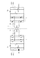
そこで、非接触給電および非接触充電の一例として図4に示すような双方向非接触給電システムが提案されている(非特許文献1参照)。同図に示すように、当該双方向非接触給電システムは、インバータまたはコンバータとして機能する電力変換装置1,2、スイッチ手段SW1,SW2で交互に選択される直流電源DC1,DC2、スイッチ手段SW4,SW3で交互に選択される負荷R2,R1ならびにノイズカット用のリアクトルL1,L2および平滑用のコンデンサC3,C4を有している。一方側の電力変換装置1と他方側の電力変換装置2とは非接触トランス3を介して電磁結合され、双方向の電力授受を行うようになっている。すなわち、電力変換装置1をインバータとして機能させる場合にはスイッチ手段SW1を投入するとともに、スイッチ手段SW4を投入して電力変換装置2をコンバータとして機能させる。逆の場合には、スイッチ手段SW2を投入するとともに、スイッチ手段SW3を投入して電力変換装置2をインバータとして機能させるとともに、電力変換装置1をコンバータとして機能させる。ここで、非接触トランス3とは、一方側のコイル3Aと他方側のコイル3Bとを分割し、故意にギャップを介して相対向させたトランスをいう。
Then, the bidirectional non-contact electric power feeding system as shown in FIG. 4 is proposed as an example of non-contact electric power feeding and non-contact charging (refer nonpatent literature 1). As shown in the figure, the bidirectional non-contact power feeding system includes
このように非接触トランス3を介して電力の授受を行わせる場合、漏れ磁束の増大に伴い一方側のコイル3Aと他方側のコイル3Bとの双方と鎖交する磁束が減少し、相互インダクタンスMが小さくなる。このため、非接触トランス3を用いる非接触給電方式では、10kHz以上の高い周波数ωでコイル電流をスイッチングしたり、コンデンサC1,C2をコイル3A,3Bの近傍へ挿入して良好な電力伝送を担保している。加えて、双方向性を保証するためには一方側と他方側の回路を同様に構成する必要があり、図4では最もシンプルな構成である直列−直列型のコンデンサ配置としている。
When power is exchanged through the non-contact transformer 3 in this way, the magnetic flux interlinking with both the one
かかる双方向非接触給電システムにおいて、高い電力伝送効率を維持するため、原則負荷R1,R2の抵抗値は相互リアクタンスωMよりも小さくする必要がある。負荷R1,R2の抵抗値が小さい場合、必然的に直流電源DC1,DC2の電圧が12V程度の低電圧となる。 In such a bidirectional non-contact power supply system, in order to maintain high power transmission efficiency, in principle, the resistance values of the loads R1 and R2 need to be smaller than the mutual reactance ωM. When the resistance values of the loads R1 and R2 are small, the voltage of the DC power sources DC1 and DC2 is inevitably a low voltage of about 12V.
ところで、実際の電気自動車に搭載されるバッテリーは300V程度と高電圧である。すなわち、駆動電圧が300V程度の電気自動車のバッテリーを利用した双方向非接触給電システムでは、ジュール熱の低減の観点から負荷電流Iを小さくする必要がある。このためには、負荷R1,R2の抵抗値を大きくする必要がある。 By the way, a battery mounted on an actual electric vehicle has a high voltage of about 300V. That is, in the bidirectional non-contact power feeding system using the battery of an electric vehicle having a driving voltage of about 300V, it is necessary to reduce the load current I from the viewpoint of reducing Joule heat. For this purpose, it is necessary to increase the resistance values of the loads R1, R2.
ところが、図4に示すシステム構成において負荷R1,R2の抵抗値を大きくすれば、
高い電力伝送効率を維持させることが困難になる。
However, if the resistance values of the loads R1 and R2 are increased in the system configuration shown in FIG.
It becomes difficult to maintain high power transmission efficiency.
本発明は、上記従来技術に鑑み、電源が高電圧であっても良好な伝送効率を維持しつつ対称性も保持して非接触の双方向給電を実現し得る双方向非接触給電システムを提供することを目的とする。 The present invention provides a bidirectional non-contact power feeding system capable of realizing non-contact bidirectional power feeding while maintaining good transmission efficiency and maintaining symmetry even when the power source is at a high voltage in view of the above-described prior art. The purpose is to do.
上記目的を達成する本発明の構成は次の知見を基礎とするものである。いま、図4に示す非接触トランス3における電力の伝送側のコイル3Aに直列にコンデンサを接続するとともに受電側のコイル3Bに並列に他のコンデンサを接続した場合、すなわち非接触トランス3のコイル3A,3Bの両端にコンデンサの直列−並列接続を行った場合を考える。この場合の等価回路において、式(1)が成立するように容量C(並列に接続した他のコンデンサの容量)と高周波電源の周波数ωを決める。
The configuration of the present invention that achieves the above object is based on the following knowledge. Now, when a capacitor is connected in series to the
(1/jωC)+jωL=0 ・・・・(1)
なお、上式(1)中、Lは非接触トランス3の自己インダクタンスである。
(1 / jωC) + jωL = 0 (1)
In the above formula (1), L is the self-inductance of the non-contact transformer 3.
上式(1)が成立している場合には、高周波電源から見たインピーダンスZは式(2)で表される。
Z=(1/jωCp)+jω(1−k2)L+k2R ・・・・(2)
なお、上式(2)中、容量Cpは直列に接続したコンデンサの容量、Rは受電側の抵抗、kは非接触トランス3における結合係数である。
When the above equation (1) holds, the impedance Z viewed from the high-frequency power source is represented by equation (2).
Z = (1 / jωC p ) + jω (1-k 2 ) L + k 2 R (2)
In the above equation (2), the capacitance C p is the capacitance of the capacitors connected in series, R is the resistance on the power receiving side, and k is the coupling coefficient in the non-contact transformer 3.
一方、伝送側の電圧をV1、電流をI1、受電側の電圧をV2、電流をI2とするとき式(3)および式(4)の関係が成立している。
V2/V1=1/k ・・・・(3)
I2/I1=k ・・・・(4)
On the other hand, when the transmission-side voltage is V 1 , the current is I 1 , the power-receiving-side voltage is V 2 , and the current is I 2 , the relationships of Expressions (3) and (4) are established.
V 2 / V 1 = 1 / k ···· (3)
I 2 / I 1 = k (4)
したがって、この場合の電力伝送効率は式(5)となる。
P2/P1=1 ・・・・(5)
Therefore, the power transmission efficiency in this case is expressed by Equation (5).
P 2 / P 1 = 1 (5)
これらの解析結果を参酌すると、式(5)の通り高い伝送効率を維持しつつ、式(2)の通り負荷R1,R2の抵抗値Rが大きくても電力伝送が成立するため、直列−並列のコンデンサ配置は高電圧系に適した回路構成であることが分かる。 Considering these analysis results, while maintaining high transmission efficiency as in equation (5), power transmission is established even if resistance values R of loads R1 and R2 are large as in equation (2). It can be seen that this capacitor arrangement is a circuit configuration suitable for a high voltage system.
ただ、この場合には、伝送側と受電側とを逆転させると双方向性を担保することはできない。そこで、高電圧駆動であっても良好な伝送効率を維持しつつ対称性も保持して非接触の双方向給電を実現するためには、さらなる工夫が必要になる。 However, in this case, the bidirectionality cannot be secured if the transmission side and the power receiving side are reversed. Therefore, in order to realize non-contact bidirectional power feeding while maintaining symmetry while maintaining good transmission efficiency even with high voltage driving, further ingenuity is required.
本発明は上記知見に基づき、上述の如き目的を達成するもので、その第1の態様は、
一方側と他方側とで非接触で双方向の電気エネルギーの授受を行うよう相互に離隔して配設されている前記一方側および他方側のコイルを有する非接触トランスと、
第1および第2のスイッチ手段を介して前記コイルに直列および並列に接続されるコンデンサを有して前記コイルとの間で共振回路を形成する一方側および他方側の双方向共振回路と、
前記双方向共振回路にそれぞれ接続されるとともにインバータおよびコンバータとして動作される一方側および他方側の電力変換装置と、
一方側および他方側で前記各電力変換装置にそれぞれ第3および第4のスイッチ手段を介して並列に接続された直流電源および負荷と、
一方側から他方側に電力を供給する際には、一方側において前記第3のスイッチ手段を制御することにより前記電力変換装置を前記直流電源を電源とするインバータとして動作させるとともに前記双方向共振回路においては前記コンデンサが前記コイルに直列に接続されるように前記第1のスイッチ手段を制御する一方、他方側において前記双方向共振回路の前記コンデンサが前記コイルに並列に接続されるように前記第2のスイッチ手段を制御するとともに前記第4のスイッチ手段を制御して前記電力変換装置を前記負荷に電力を供給するコンバータとして動作させるように制御し、他方側から一方側に電力を供給する際には逆の動作になるように制御する制御手段とを有することを特徴とする双方向非接触給電システムにある。
The present invention achieves the above-described object based on the above findings, and the first aspect thereof is
A non-contact transformer having coils on the one side and the other side that are spaced apart from each other so as to transfer and receive bidirectional electrical energy in a non-contact manner on one side and the other side;
A bidirectional resonant circuit on one side and the other side having a capacitor connected in series and parallel to the coil via first and second switch means and forming a resonant circuit with the coil;
Power converters on one side and the other side connected to the bidirectional resonant circuit and operated as an inverter and a converter,
A DC power source and a load connected in parallel to the respective power converters on the one side and the other side via third and fourth switch means, respectively;
When power is supplied from one side to the other side, the third switch means is controlled on one side to operate the power converter as an inverter using the DC power supply as a power source, and the bidirectional resonant circuit The first switch means is controlled so that the capacitor is connected in series to the coil, while the capacitor of the bidirectional resonant circuit is connected in parallel to the coil on the other side. When controlling the second switch means and controlling the fourth switch means to operate the power converter as a converter for supplying power to the load, and supplying power from the other side to one side The bidirectional non-contact power feeding system has control means for controlling so as to perform the reverse operation.
本態様によれば、非接触トランスを介して双方向の電力伝送を行う双方向非接触給電システムにおいて、一方側から他方側に電力を供給する場合には、一方側のコンデンサが非接触トランスの一方側のコイルに直列に接続され、他方側のコンデンサが他方側のコイルに並列に接続されるようにしているので、電源が高電圧であっても高い電力伝送効率を維持しつつ所定の電力伝送が可能になる。同時に、他方側から一方側に電力を供給する場合には、他方側のコンデンサが非接触トランスの他方側のコイルに直列に接続され、一方側のコンデンサが一方側のコイルに並列に接続されるようにしているので、双方向性が犠牲にされることはない。このように、電源が高電圧である場合の電力伝送効率を高く維持しつつ非接触トランスを介した双方向電力伝送を良好に行うことができる。 According to this aspect, in a bidirectional contactless power feeding system that performs bidirectional power transmission via a contactless transformer, when power is supplied from one side to the other side, the capacitor on one side is connected to the contactless transformer. Since it is connected in series to the coil on one side and the capacitor on the other side is connected in parallel to the coil on the other side, even if the power supply is at a high voltage, a predetermined power is maintained while maintaining high power transmission efficiency. Transmission is possible. At the same time, when power is supplied from the other side to one side, the capacitor on the other side is connected in series to the coil on the other side of the non-contact transformer, and the capacitor on one side is connected in parallel to the coil on one side. As a result, the interactivity is not sacrificed. In this way, bidirectional power transmission through the non-contact transformer can be performed satisfactorily while maintaining high power transmission efficiency when the power source is at a high voltage.
本発明の第2の態様は、
第1の態様に記載する双方向非接触給電システムにおいて、
一方側と他方側の前記電力変換装置と前記負荷および直流電源との間に昇降圧コンバータを配設するとともに、
一方側から他方側に電力を供給する際には、前記制御手段が一方側の昇降圧コンバータを必要に応じて昇圧コンバータとして動作させるとともに他方側の昇降圧コンバータを降圧コンバータとして動作させるように制御する一方、他方側から一方側に電力を供給する際には逆の動作になるように制御するものであることを特徴とする双方向非接触給電システムにある。
The second aspect of the present invention is:
In the bidirectional contactless power feeding system described in the first aspect,
While arranging a buck-boost converter between the power converter on one side and the other side and the load and DC power supply,
When supplying power from one side to the other side, the control means controls the one side buck-boost converter to operate as a step-up converter as needed and the other side buck-boost converter to operate as a step-down converter. On the other hand, when the electric power is supplied from the other side to the one side, the bidirectional non-contact power feeding system is controlled to perform the reverse operation.
本態様によれば、電力変換装置の入力電圧または出力電圧を任意に調整することができる。この結果、式(3)より0<k<1であることから、受電側の電圧V2は伝送側の電圧V1よりも高い電圧となるが、受電側の昇降圧コンバータを降圧コンバータとして動作させることにより、定格通りの性能を発揮させることが可能になる。 According to this aspect, the input voltage or the output voltage of the power converter can be arbitrarily adjusted. As a result, since 0 <k <1 from Equation (3), the power receiving side voltage V 2 is higher than the transmission side voltage V 1 , but the power receiving side buck-boost converter operates as a step-down converter. By doing so, it becomes possible to exhibit the performance as rated.
さらに、特に複数のバッテリーをユニット化したモジュールで直流電源を形成した場合等には、その冗長性を確保し得る。 Further, the redundancy can be ensured particularly when a DC power source is formed by a module in which a plurality of batteries are unitized.
本発明の第3の態様は、
第1の態様または第2の態様に記載する双方向非接触給電システムにおいて、
前記非接触トランスの一方側の前記コイルは家側に、他方側の前記コイルは移動により前記一方側のコイルに相対向し得るように車両側にそれぞれ配設されるとともに、前記一方側の前記双方向共振回路、電力変換装置、直流電源および負荷は前記家側に配設され、前記他方側の前記双方向共振回路、電力変換装置、直流電源および負荷は前記車両に搭載されていることを特徴とする双方向非接触給電システムにある。
The third aspect of the present invention is:
In the bidirectional contactless power feeding system described in the first aspect or the second aspect,
The coil on one side of the non-contact transformer is disposed on the house side, and the coil on the other side is disposed on the vehicle side so as to be opposed to the coil on the one side by movement. A bidirectional resonant circuit, a power converter, a DC power source and a load are disposed on the house side, and the bidirectional resonant circuit, power converter, DC power source and a load on the other side are mounted on the vehicle. It is in the bidirectional non-contact power feeding system characterized.
車両には、補機類に12V等を供給する鉛蓄電池と、モーターを駆動させるため300V相当の電圧を供給するバッテリーが搭載されている。本態様における直流電源および負荷は後者を対象とする。 The vehicle is equipped with a lead storage battery for supplying 12V or the like to auxiliary machinery and a battery for supplying a voltage equivalent to 300V for driving the motor. The DC power supply and load in this embodiment are for the latter.
本態様によれば、上述の如き理由により、特に高電圧系統となる家と車両間の双方向非接触給電システムとして有用なものとなる。また、車載バッテリーは、通常多数のバッテリーをユニット化したモジュールで形成されているので、この場合の冗長性も確保し得る。 According to this aspect, for the reasons as described above, it is particularly useful as a bidirectional non-contact power feeding system between a house and a vehicle that become a high voltage system. Further, since the vehicle-mounted battery is usually formed by a module in which a large number of batteries are unitized, redundancy in this case can be ensured.
本発明によれば、非接触トランスを用いた双方向非接触給電システムにおいて使用する電源が高電圧であっても双方向性を犠牲にすることなく、高い電力伝送効率を維持しつつ双方向の非接触給電が可能になる。 According to the present invention, even if the power source used in the bidirectional contactless power feeding system using a contactless transformer is a high voltage, the bidirectional power supply is maintained without sacrificing the bidirectionality, while maintaining the high power transmission efficiency. Non-contact power supply becomes possible.
以下、本発明の実施の形態を図面に基づき詳細に説明する。
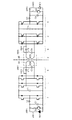
図1は本発明の実施の形態に係る双方向非接触給電システムを示すブロック線図である。同図に示すように、本形態に係る双方向非接触給電システムは、図4に示す双方向非接触給電システムと同様に、非接触トランス3により分離されて対称に構成されている一方側(図中の左側;以下同じ)と他方側(図中の右側;以下同じ)とからなり、図4に示すシステムに双方向共振回路5,6および昇降圧コンバータ7,8を追加したものである。その他の構成は図4に示す双方向非接触給電システムと同様であるので、図4と同一部分には同一番号を付し、重複する説明は省略する。
Hereinafter, embodiments of the present invention will be described in detail with reference to the drawings.
FIG. 1 is a block diagram showing a bidirectional non-contact power feeding system according to an embodiment of the present invention. As shown in the figure, the bidirectional non-contact power feeding system according to the present embodiment is separated by the non-contact transformer 3 and symmetrically configured like the bidirectional non-contact power feeding system shown in FIG. The left side in the figure; the same applies to the following, and the other side (the right in the figure; the same applies to the following). The system shown in FIG. . Since the other configuration is the same as that of the bidirectional non-contact power feeding system shown in FIG. 4, the same parts as those in FIG.
図1に示すように、双方向共振回路5,6はコイル3A,3Bに直列に接続されたコンデンサC1,C2と、コイル3A,3Bに並列に接続されたコンデンサC5,C6とからなり、コンデンサC1,C2の両端はスイッチ手段SW5、SW6で短絡可能に構成されるとともに、コンデンサC5,C6はスイッチ手段SW7,SW8によりコイル3A,3Bの両端間に選択的に接続可能に構成されている。ここで、一方側から他方側へ電力伝送を行う場合には、スイッチ手段SW5およびスイッチ手段SW7がOFF状態、スイッチ手段SW6およびスイッチ手段SW8がON状態になるように制御される。また、他方側から一方側へ電力伝送を行う場合には、スイッチ手段SW6およびスイッチ手段SW8がOFF状態、スイッチ手段SW5およびスイッチ手段SW7がON状態になるように制御される。かくして、前者の場合には一方側から他方側に向けて非接触トランス3を挟んでコンデンサC1およびコンデンサC6が直列−並列接続され、後者の場合には他方側から一方側に向けて非接触トランス3を挟んでコンデンサC2およびコンデンサC5が直列−並列接続される。
As shown in FIG. 1, the bidirectional
かくして一方側と他方側との間での双方向性が担保されると同時に電源が高電圧であっても電力伝送効率を高く維持しつつ非接触トランスを介した非接触給電を行うことができる。 Thus, bidirectionality between the one side and the other side is ensured, and at the same time, even when the power source is at a high voltage, non-contact power feeding can be performed via a non-contact transformer while maintaining high power transmission efficiency. .
昇降圧コンバータ7は、リアクトルL3およびコンデンサC7とともに一方側で直流電源DC1および負荷R1と電力変換装置1との間に接続され、昇降圧コンバータ8は、リアクトルL4およびコンデンサC8とともに他方側で直流電源DC2および負荷R2と電力変換装置2との間に接続されている。かくして、一方側から他方側に電力を伝送する場合には、スイッチ手段SW1がON状態となって直流電源DC1を昇降圧コンバータ7の入力側に接続するとともにスイッチ手段SW4がON状態となって負荷R2を昇降圧コンバータ8の出力側に接続する。反対に、他方側から一方側に電力を伝送する場合には、スイッチ手段SW2がON状態となって直流電源DC2を昇降圧コンバータ8の入力側に接続するとともにスイッチ手段SW3がON状態となって負荷R1を昇降圧コンバータ7の出力側に接続するように制御される。
The buck-
かかる昇降圧コンバータ7,8はそのスイッチング制御により、電力変換装置1,2に印加する入力電圧を所定の値に調整するとともに、負荷R2,R1に印加する入力電圧を所定の値に調整する。
The buck-
上述の電力変換装置1,2の所定周波数(例えば10kHz)でのスイッチング、昇降圧コンバータ7,8の電圧調整のためのスイッチングおよびスイッチ手段SW1〜SW8の開閉制御は図示しない制御手段により行われる。
The above-described switching of the
上述の如き本形態によれば、一方側から他方側へ電力伝送を行う場合には、インバータとして機能させる一方側の電力変換装置1に、スイッチ手段SW1を介して一方側の直流電源DC1を接続し、コンバータとして機能させる他方側の電力変換装置2に、スイッチ手段SW4を介して他方側の負荷R2を接続するとともに、他方側から一方側に電力を供給する場合には、他方側の機器と一方側の機器の機能が逆転されるように接続することができるので、双方向の電力伝送を良好に行うことができる。
According to the present embodiment as described above, when power is transmitted from one side to the other side, the DC power source DC1 on one side is connected to the
ここで、本形態における非接触トランス3のコイル3A,3Bには、電力伝送の方向に沿いコンデンサC1,C6またはコンデンサC2,C5が直列−並列接続されるので、高い電力伝送効率を保持して高い電圧での電力伝送を実現することが可能になる。
Here, since the capacitors C1 and C6 or the capacitors C2 and C5 are connected in series-parallel along the direction of power transmission to the
さらに、上述の如きコンデンサC1,C2,C5,C6の直列−並列に関する接続関係はスイッチ手段SW5〜SW8の切換えにより一方側と他方側とで対称な構成とすることができるので、双方向性が犠牲にされることもない。 Furthermore, the connection relationship regarding the series-parallel connection of the capacitors C1, C2, C5 and C6 as described above can be made symmetrical on one side and the other side by switching the switch means SW5 to SW8. There is no sacrifice.
また、本形態では昇降圧コンバータ7,8を具備するので、電力変換装置1,2の入力電圧または出力電圧を任意に調整することができる。この結果、直流電源DC1,DC2や負荷R1,R2の性能にかかわらず電力変換装置1,2に対する所望の入出力電圧に対処し得る。特に複数のバッテリーをユニット化したモジュールで直流電源を形成した場合等には、その冗長性を確保し得る。すなわち、例えばバッテリーの放電に伴い出力電圧が単調減少した場合でもその出力電圧の昇圧により定格通りの性能を発揮させることが可能になる。
Moreover, since the step-up / step-down
また、一方側および他方側の具体的な構成は、上述の如き構成を備えていれば、それ以上特別な制限はないが、例えば一方側を家等の固定部とし、他方側を車両とした場合の双方向非接触給電システムとして有用なものとなる。この場合、非接触トランス3のコイル3Aを家側に、コイル3Bを車両の移動によりコイル3Aに相対向し得るように車両側に配設すれば良い。そして、電力変換装置1、双方向共振回路5、昇降圧コンバータ7、直流電源DC1および負荷R1を家側の固定機器として配設する。一方、電力変換装置2、双方向共振回路6、昇降圧コンバータ8、直流電源DC2および負荷R2は車両側の機器として車両に搭載されている。ここで、車載側の機器はハイブリッド電気自動車や電気自動車に装備されている機器をそのまま流用できる。
Further, the specific configuration on one side and the other side is not particularly limited as long as it has the above-described configuration. For example, one side is a fixed part such as a house and the other side is a vehicle. This is useful as a bidirectional non-contact power feeding system. In this case, the
したがって、一方側を家側とし、他方側を車両として通常は家側から車載バッテリーに充電を行い、非常時に車載バッテリーを電源として家側の負荷の電力を賄う等の使用態様に適用して有用なシステムを構築することができる。また、この場合、車載バッテリーは、通常多数のバッテリーをユニット化したモジュールで形成されているので、その冗長性も確保し得る。 Therefore, it is useful to apply to usage modes where one side is the house side, the other side is the vehicle, and the in-vehicle battery is normally charged from the house side, and the in-vehicle battery is used as a power source to cover the load on the house side in an emergency. System can be constructed. Further, in this case, since the vehicle-mounted battery is usually formed by a module in which a large number of batteries are unitized, the redundancy can be ensured.
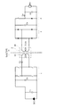
図2は、図1に示す双方向非接触給電システムにより一方側から他方側へ電力伝送を行う場合の態様の一例を示すブロック線図である。同図に示す例では直流電源DC1の出力電圧をそのまま(必要に応じ昇降圧コンバータ7により電圧調整を行っても良い)電力変換装置1に印加するとともにコンデンサC1,C6が直列−並列に接続された非接触トランス3を介して他方側に伝送された電力を昇降圧コンバータ8で適切な負荷電圧に降圧して負荷R2に供給している。
FIG. 2 is a block diagram showing an example of a mode in which power is transmitted from one side to the other side by the bidirectional contactless power feeding system shown in FIG. In the example shown in the figure, the output voltage of the DC power source DC1 is applied to the
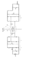
一方、図3は、図1に示す双方向非接触給電システムにより逆に(他方側から一方側へ)電力伝送を行う場合の態様の一例を示すブロック線図である。同図に示す例では直流電源DC2の出力電圧をそのまま(必要に応じ昇降圧コンバータ8により電圧調整を行っても良い)電力変換装置2に印加するとともにコンデンサC2,C5が直列−並列に接続された非接触トランス3を介して一方側に伝送された電力を昇降圧コンバータ7で適切な負荷電圧に降圧して負荷R1に供給している。
On the other hand, FIG. 3 is a block diagram illustrating an example of a mode in which power transmission is performed reversely (from the other side to one side) by the bidirectional contactless power feeding system illustrated in FIG. 1. In the example shown in the figure, the output voltage of the DC power source DC2 is applied to the
このように昇降圧コンバータ7,8を有する場合には、各部の電圧を任意に調節することができ、種々の定格の直流電源DC1,DC2や負荷R1,R2に柔軟に対応することができるという固有の効果は発揮される。これら昇降圧コンバータ7,8は受電側の電圧値を問わなければ必ずしも必要ではない。
As described above, when the step-up / step-down
本発明は電気自動車と家等の固定設備との間で双方向に電力伝送を行うシステムを構築する産業分野において利用することができる。 INDUSTRIAL APPLICABILITY The present invention can be used in the industrial field of constructing a system for bidirectional power transmission between an electric vehicle and a fixed facility such as a house.
1、2 電力変換装置
3 非接触トランス
3A,3B コイル
5,6 双方向共振回路
7,8 昇降圧コンバータ
1, 2 Power converter
3
Claims (3)
第1および第2のスイッチ手段を介して前記コイルに直列および並列に接続されるコンデンサを有して前記コイルとの間で共振回路を形成する一方側および他方側の双方向共振回路と、
前記双方向共振回路にそれぞれ接続されるとともにインバータおよびコンバータとして動作される一方側および他方側の電力変換装置と、
一方側および他方側で前記各電力変換装置にそれぞれ第3および第4のスイッチ手段を介して並列に接続された直流電源および負荷と、
一方側から他方側に電力を供給する際には、一方側において前記第3のスイッチ手段を制御することにより前記電力変換装置を前記直流電源を電源とするインバータとして動作させるとともに前記双方向共振回路においては前記コンデンサが前記コイルに直列に接続されるように前記第1のスイッチ手段を制御する一方、他方側において前記双方向共振回路の前記コンデンサが前記コイルに並列に接続されるように前記第2のスイッチ手段を制御するとともに前記第4のスイッチ手段を制御して前記電力変換装置を前記負荷に電力を供給するコンバータとして動作させるように制御し、他方側から一方側に電力を供給する際には逆の動作になるように制御する制御手段とを有することを特徴とする双方向非接触給電システム。 A non-contact transformer having coils on the one side and the other side that are spaced apart from each other so as to transfer and receive bidirectional electrical energy in a non-contact manner on one side and the other side;
A bidirectional resonant circuit on one side and the other side having a capacitor connected in series and parallel to the coil via first and second switch means and forming a resonant circuit with the coil;
Power converters on one side and the other side connected to the bidirectional resonant circuit and operated as an inverter and a converter,
A DC power source and a load connected in parallel to the respective power converters on the one side and the other side via third and fourth switch means, respectively;
When power is supplied from one side to the other side, the third switch means is controlled on one side to operate the power converter as an inverter using the DC power supply as a power source, and the bidirectional resonant circuit The first switch means is controlled so that the capacitor is connected in series to the coil, while the capacitor of the bidirectional resonant circuit is connected in parallel to the coil on the other side. When controlling the second switch means and controlling the fourth switch means to operate the power converter as a converter for supplying power to the load, and supplying power from the other side to one side And a control means for controlling the operation to be reversed.
一方側と他方側の前記電力変換装置と前記負荷および直流電源との間に昇降圧コンバータを配設するとともに、
一方側から他方側に電力を供給する際には、前記制御手段が一方側の昇降圧コンバータを必要に応じて昇圧コンバータとして動作させるとともに他方側の昇降圧コンバータを降圧コンバータとして動作させるように制御する一方、他方側から一方側に電力を供給する際には逆の動作になるように制御するものであることを特徴とする双方向非接触給電システム。 In the bidirectional non-contact power feeding system according to claim 1,
While arranging a buck-boost converter between the power converter on one side and the other side and the load and DC power supply,
When supplying power from one side to the other side, the control means controls the one side buck-boost converter to operate as a step-up converter as needed and the other side buck-boost converter to operate as a step-down converter. On the other hand, when the electric power is supplied from the other side to the one side, the bidirectional non-contact power feeding system is controlled so as to perform the reverse operation.
前記非接触トランスの一方側の前記コイルは家側に、他方側の前記コイルは移動により前記一方側のコイルに相対向し得るように車両側にそれぞれ配設されるとともに、前記一方側の前記双方向共振回路、電力変換装置、直流電源および負荷は前記家側に配設され、前記他方側の前記双方向共振回路、電力変換装置、直流電源および負荷は前記車両に搭載されていることを特徴とする双方向非接触給電システム。 In the bidirectional contactless power feeding system according to claim 1 or 2,
The coil on one side of the non-contact transformer is disposed on the house side, and the coil on the other side is disposed on the vehicle side so as to be opposed to the coil on the one side by movement. A bidirectional resonant circuit, a power converter, a DC power source and a load are disposed on the house side, and the bidirectional resonant circuit, power converter, DC power source and a load on the other side are mounted on the vehicle. Characteristic bidirectional non-contact power feeding system.
Priority Applications (1)
| Application Number | Priority Date | Filing Date | Title |
|---|---|---|---|
| JP2011108680A JP5641540B2 (en) | 2011-05-13 | 2011-05-13 | Bi-directional contactless power supply system |
Applications Claiming Priority (1)
| Application Number | Priority Date | Filing Date | Title |
|---|---|---|---|
| JP2011108680A JP5641540B2 (en) | 2011-05-13 | 2011-05-13 | Bi-directional contactless power supply system |
Publications (2)
| Publication Number | Publication Date |
|---|---|
| JP2012244635A true JP2012244635A (en) | 2012-12-10 |
| JP5641540B2 JP5641540B2 (en) | 2014-12-17 |
Family
ID=47465795
Family Applications (1)
| Application Number | Title | Priority Date | Filing Date |
|---|---|---|---|
| JP2011108680A Expired - Fee Related JP5641540B2 (en) | 2011-05-13 | 2011-05-13 | Bi-directional contactless power supply system |
Country Status (1)
| Country | Link |
|---|---|
| JP (1) | JP5641540B2 (en) |
Cited By (10)
| Publication number | Priority date | Publication date | Assignee | Title |
|---|---|---|---|---|
| WO2014125698A1 (en) * | 2013-02-12 | 2014-08-21 | 三菱電機株式会社 | Power receiving apparatus and non-contact power supply apparatus |
| WO2014189095A1 (en) | 2013-05-21 | 2014-11-27 | 株式会社 テクノバ | Bidirectional contactless power supply device |
| JP2017220990A (en) * | 2016-06-03 | 2017-12-14 | 国立大学法人神戸大学 | Ultrasonic contactless power supply system |
| US10090709B2 (en) | 2015-03-23 | 2018-10-02 | Mitsubishi Electric Corporation | Bidirectional non-contact power supply device and bidirectional non-contact power supply system |
| WO2018189953A1 (en) | 2017-04-12 | 2018-10-18 | 三菱電機株式会社 | Power conversion device and contactless power supply system |
| JP2020150673A (en) * | 2019-03-13 | 2020-09-17 | マクセルホールディングス株式会社 | Non-contact power transmission device, power transmission device, and power receiving device |
| US11114950B2 (en) | 2017-06-22 | 2021-09-07 | Murata Manufacturing Co., Ltd. | High frequency power supply device |
| US11322985B2 (en) | 2017-09-14 | 2022-05-03 | Maxell, Ltd. | Wireless power transfer system, power transmission apparatus, and power reception apparatus |
| US12500452B2 (en) | 2020-07-07 | 2025-12-16 | Samsung Electronics Co., Ltd. | Electronic device wirelessly receiving power, and operating method therefor |
| US12522088B2 (en) | 2020-02-13 | 2026-01-13 | Ihi Corporation | Power supply device and power supply system |
Citations (6)
| Publication number | Priority date | Publication date | Assignee | Title |
|---|---|---|---|---|
| JPH0696300A (en) * | 1992-09-14 | 1994-04-08 | Masuo Ikeuchi | Non-contact type ic card by electromagnetic induction coupling and reader/writer |
| WO2010028092A1 (en) * | 2008-09-02 | 2010-03-11 | Qualcomm Incorporated | Bidirectional wireless power transmission |
| WO2010125864A1 (en) * | 2009-04-27 | 2010-11-04 | 株式会社村田製作所 | Wireless power transmission terminal |
| JP2011045195A (en) * | 2009-08-21 | 2011-03-03 | Saitama Univ | Non-contact power feeding device and non-contact power feeding method |
| WO2011127449A2 (en) * | 2010-04-08 | 2011-10-13 | Qualcomm Incorporated | Wireless power transmission in electric vehicles |
| WO2012101907A1 (en) * | 2011-01-26 | 2012-08-02 | 株式会社村田製作所 | Power transmission system |
-
2011
- 2011-05-13 JP JP2011108680A patent/JP5641540B2/en not_active Expired - Fee Related
Patent Citations (6)
| Publication number | Priority date | Publication date | Assignee | Title |
|---|---|---|---|---|
| JPH0696300A (en) * | 1992-09-14 | 1994-04-08 | Masuo Ikeuchi | Non-contact type ic card by electromagnetic induction coupling and reader/writer |
| WO2010028092A1 (en) * | 2008-09-02 | 2010-03-11 | Qualcomm Incorporated | Bidirectional wireless power transmission |
| WO2010125864A1 (en) * | 2009-04-27 | 2010-11-04 | 株式会社村田製作所 | Wireless power transmission terminal |
| JP2011045195A (en) * | 2009-08-21 | 2011-03-03 | Saitama Univ | Non-contact power feeding device and non-contact power feeding method |
| WO2011127449A2 (en) * | 2010-04-08 | 2011-10-13 | Qualcomm Incorporated | Wireless power transmission in electric vehicles |
| WO2012101907A1 (en) * | 2011-01-26 | 2012-08-02 | 株式会社村田製作所 | Power transmission system |
Cited By (15)
| Publication number | Priority date | Publication date | Assignee | Title |
|---|---|---|---|---|
| WO2014125698A1 (en) * | 2013-02-12 | 2014-08-21 | 三菱電機株式会社 | Power receiving apparatus and non-contact power supply apparatus |
| JPWO2014125698A1 (en) * | 2013-02-12 | 2017-02-02 | 三菱電機株式会社 | Power receiving device and non-contact power feeding device |
| WO2014189095A1 (en) | 2013-05-21 | 2014-11-27 | 株式会社 テクノバ | Bidirectional contactless power supply device |
| US10090709B2 (en) | 2015-03-23 | 2018-10-02 | Mitsubishi Electric Corporation | Bidirectional non-contact power supply device and bidirectional non-contact power supply system |
| JP2017220990A (en) * | 2016-06-03 | 2017-12-14 | 国立大学法人神戸大学 | Ultrasonic contactless power supply system |
| CN110463010A (en) * | 2017-04-12 | 2019-11-15 | 三菱电机株式会社 | Power conversion device and non-contact power supply system |
| WO2018189953A1 (en) | 2017-04-12 | 2018-10-18 | 三菱電機株式会社 | Power conversion device and contactless power supply system |
| CN110463010B (en) * | 2017-04-12 | 2021-04-20 | 三菱电机株式会社 | Power conversion device and non-contact power supply system |
| US11095156B2 (en) | 2017-04-12 | 2021-08-17 | Mitsubishi Electric Corporation | Power conversion device and non-contact power supplying system |
| US11114950B2 (en) | 2017-06-22 | 2021-09-07 | Murata Manufacturing Co., Ltd. | High frequency power supply device |
| US11322985B2 (en) | 2017-09-14 | 2022-05-03 | Maxell, Ltd. | Wireless power transfer system, power transmission apparatus, and power reception apparatus |
| JP2020150673A (en) * | 2019-03-13 | 2020-09-17 | マクセルホールディングス株式会社 | Non-contact power transmission device, power transmission device, and power receiving device |
| JP7246977B2 (en) | 2019-03-13 | 2023-03-28 | マクセル株式会社 | Contactless power transmission device, power transmission device, and power receiving device |
| US12522088B2 (en) | 2020-02-13 | 2026-01-13 | Ihi Corporation | Power supply device and power supply system |
| US12500452B2 (en) | 2020-07-07 | 2025-12-16 | Samsung Electronics Co., Ltd. | Electronic device wirelessly receiving power, and operating method therefor |
Also Published As
| Publication number | Publication date |
|---|---|
| JP5641540B2 (en) | 2014-12-17 |
Similar Documents
| Publication | Publication Date | Title |
|---|---|---|
| JP5641540B2 (en) | Bi-directional contactless power supply system | |
| US20240116375A1 (en) | Wireless power system | |
| CN109808522B (en) | Composite bidirectional integrated charger for vehicles | |
| CN110588380B (en) | Chargeable and dischargeable energy storage device, wireless charging system and electric automobile | |
| JP6093497B2 (en) | Apparatus for energy transfer using on-board power electronic circuit with high frequency transformer isolation and method of manufacturing the same | |
| KR101733931B1 (en) | Apparatus for energy transfer using converter and method of manufacturing same | |
| CN106464031B (en) | Wireless Power Transfer System Using Load Feedback | |
| EP2814136B1 (en) | Bidirectional contactless power supply system | |
| CN108688485B (en) | Induction and conduction type vehicle-mounted charging system | |
| JP5794563B2 (en) | Contactless power supply system | |
| CN112224057B (en) | Vehicle and energy conversion device and power system thereof | |
| CN103733471B (en) | Charge and discharge device | |
| CN102835002A (en) | power supply | |
| CN112389177B (en) | Integrated electric drive system and electric vehicle comprising same | |
| US20250211017A1 (en) | Dc fast charge booster circuit integration with the battery current control module | |
| CN119652126A (en) | Isolated high voltage DC/DC converter with battery current control module components | |
| JP2014217117A (en) | Non-contact power feeding system | |
| CN112224051A (en) | A vehicle and its energy conversion device and power system | |
| KR102824140B1 (en) | Automotive battery charger, related vehicles and implementation method | |
| Benomar et al. | Design and modeling of V2G inductive charging system for light-duty Electric Vehicles | |
| US12136888B2 (en) | Composite DC-DC converter | |
| JP6953634B2 (en) | Vehicle charger with DC / DC converter | |
| Khalilian et al. | A hybrid topology wireless power transfer system with constant current or constant voltage output for battery charging application | |
| KR102202495B1 (en) | Controller for charging battery in vehicle and operating method thereof | |
| CN219643663U (en) | Charging devices, electronic equipment and vehicles |
Legal Events
| Date | Code | Title | Description |
|---|---|---|---|
| A621 | Written request for application examination |
Free format text: JAPANESE INTERMEDIATE CODE: A621 Effective date: 20140210 |
|
| A977 | Report on retrieval |
Free format text: JAPANESE INTERMEDIATE CODE: A971007 Effective date: 20141014 |
|
| TRDD | Decision of grant or rejection written | ||
| A01 | Written decision to grant a patent or to grant a registration (utility model) |
Free format text: JAPANESE INTERMEDIATE CODE: A01 Effective date: 20141022 |
|
| A61 | First payment of annual fees (during grant procedure) |
Free format text: JAPANESE INTERMEDIATE CODE: A61 Effective date: 20141022 |
|
| R150 | Certificate of patent or registration of utility model |
Ref document number: 5641540 Country of ref document: JP Free format text: JAPANESE INTERMEDIATE CODE: R150 |
|
| R250 | Receipt of annual fees |
Free format text: JAPANESE INTERMEDIATE CODE: R250 |
|
| R250 | Receipt of annual fees |
Free format text: JAPANESE INTERMEDIATE CODE: R250 |
|
| LAPS | Cancellation because of no payment of annual fees |