JP2012244233A - Onu, time synchronization method and time synchronization program - Google Patents
Onu, time synchronization method and time synchronization program Download PDFInfo
- Publication number
- JP2012244233A JP2012244233A JP2011109518A JP2011109518A JP2012244233A JP 2012244233 A JP2012244233 A JP 2012244233A JP 2011109518 A JP2011109518 A JP 2011109518A JP 2011109518 A JP2011109518 A JP 2011109518A JP 2012244233 A JP2012244233 A JP 2012244233A
- Authority
- JP
- Japan
- Prior art keywords
- control unit
- onu
- time
- olt
- local timer
- Prior art date
- Legal status (The legal status is an assumption and is not a legal conclusion. Google has not performed a legal analysis and makes no representation as to the accuracy of the status listed.)
- Withdrawn
Links
Images


Landscapes
- Small-Scale Networks (AREA)
- Synchronisation In Digital Transmission Systems (AREA)
Abstract
Description
この発明は、冗長構成を有するOLTとの間で通信を行うONU、このONUによる時刻同期方法および時刻同期プログラムに関するものである。 The present invention relates to an ONU that performs communication with an OLT having a redundant configuration, a time synchronization method using the ONU, and a time synchronization program.
従来のアクセス系ネットワークとして、GE−PON(Giga bit Ethernet(登録商標/以下、記載を省略する)−Passive Optical Network)システムが知られている(例えば非特許文献1参照)。このGE−PONシステムは、複数の加入者側通信装置(ONU:Optical Network Unit)がスターカプラを介して光ファイバケーブルで局側通信装置(OLT:Optical Line Terminal)に接続されるものであり、複数のONUが単一のOLTを共有するため経済的なネットワークの構築が可能である。 As a conventional access network, a GE-PON (Gigabit Ethernet (registered trademark / hereinafter, omitted) -Passive Optical Network) system is known (see, for example, Non-Patent Document 1). In this GE-PON system, a plurality of subscriber side communication devices (ONU: Optical Network Unit) are connected to a station side communication device (OLT: Optical Line Terminal) via an optical fiber cable via a star coupler. Since a plurality of ONUs share a single OLT, an economical network can be constructed.
このONUとOLT内の加入者線終端機能部(OSU:Optical Subscriber Unit)との間での通信は、MPCP(Multi−Point Control Protocol)メッセージを用いて行われる。このMPCPメッセージには、ONUに対してデータ信号の送信許可を通知するためのGATEメッセージや、OLTに対して送信要求するデータ信号の蓄積量を通知するためのREPORTメッセージなどが挙げられ、これらはOLT内のローカルタイマ(Local timer)を基準に生成される。 Communication between the ONU and a subscriber line termination function unit (OSU: Optical Subscriber Unit) in the OLT is performed using an MPCP (Multi-Point Control Protocol) message. Examples of the MPCP message include a GATE message for notifying the ONU of transmission permission of the data signal, and a REPORT message for notifying the accumulated amount of the data signal requested to be transmitted to the OLT. Generated based on a local timer in the OLT.
このPONシステムによる通信は、OLTとONUとの間でMPCP Discoveryシーケンスを実行することによって行う。このシーケンスでは、まず、OLTが、OLT内のローカルタイマに基づいて設定したデータ信号の送信開始時刻と送信量情報を含むGATEメッセージをONUに送信する。そして、ONUが、このGATEメッセージを受信した後、送信要求するデータ信号の蓄積量情報を含むREPORTメッセージをOLTに送信する。そして、ONUは、ONU内のローカルタイマがGATEメッセージに含まれる送信開始時刻を示した際に、GATEメッセージに含まれる送信量を上限として、蓄積しているデータ信号をOLTに送信する。
ここで、各ONUが、OLTにより設定された個々に異なる送信開始時刻に、設定された送信量のデータ信号を送信することで、スターカプラで各データ信号の多重化を行った際にデータ信号同士が衝突することを防止できる。この際、各ONUが正しく送信開始時刻にデータ送信を行うためには、各ONU内のローカルタイマがOLT内のローカルタイマと同期されている必要がある。
Communication by the PON system is performed by executing an MPCP Discovery sequence between the OLT and the ONU. In this sequence, first, the OLT transmits a GATE message including a data signal transmission start time and transmission amount information set based on a local timer in the OLT to the ONU. Then, after receiving the GATE message, the ONU transmits a REPORT message including the accumulated amount information of the data signal requested to be transmitted to the OLT. Then, when the local timer in the ONU indicates the transmission start time included in the GATE message, the ONU transmits the accumulated data signal to the OLT with the transmission amount included in the GATE message as an upper limit.
Here, each ONU transmits a data signal of a set transmission amount at an individually different transmission start time set by the OLT, so that the data signal is multiplexed when each data signal is multiplexed by the star coupler. It can prevent that each other collides. At this time, in order for each ONU to transmit data correctly at the transmission start time, the local timer in each ONU needs to be synchronized with the local timer in the OLT.
そこでPONシステムでは、OLTとONUとの間でMPCP Discoveryシーケンスを実行する際に、MPCP Local timer syncronizationシーケンスを実行し、時刻同期を行っている(例えば非特許文献2参照)。すなわち、OLTが、GATEメッセージをONUに送信する際に、OLT内のローカルタイマの現在値(タイムスタンプ値)をタイムシンク(Time Sync)情報としてGATEメッセージに埋め込んでいる。そしてONUは、受信したGATEメッセージに含まれるタイムシンク情報が示すタイムスタンプ値に合わせて、ONU内のローカルタイマの現在値(タイムスタンプ値)を更新することで時刻同期を行っている。 Therefore, in the PON system, when the MPCP Discovery sequence is executed between the OLT and the ONU, the MPCP Local timer synchronization sequence is executed to perform time synchronization (for example, refer to Non-Patent Document 2). That is, when the OLT transmits a GATE message to the ONU, the current value (time stamp value) of the local timer in the OLT is embedded in the GATE message as time sync information. The ONU performs time synchronization by updating the current value (time stamp value) of the local timer in the ONU in accordance with the time stamp value indicated by the time sync information included in the received GATE message.
その後、ONUとOLTとの間で、GATEメッセージおよびREPORTメッセージを繰り返すことで通信を行う。またこの際、OLTは、ONUに時刻管理させるためのローカルタイマ情報(OLT内のローカルタイマの現在値)をGATEメッセージに埋め込んでONUに送信し、ONUはGATEメッセージに含まれるローカルタイマ情報に基づいてONU内のローカルタイマの時刻管理を行っている。また、ONUは、時刻管理を行う際に、ローカルタイマ情報が示すタイムスタンプ値に対するONU内のローカルタイマのタイムスタンプ値のドリフト量が規定値内であるかを判断し、規定値以上の場合にはタイムスタンプドリフトエラーとして検出する。 Thereafter, communication is performed between the ONU and the OLT by repeating a GATE message and a REPORT message. At this time, the OLT embeds local timer information (current value of the local timer in the OLT) for causing the ONU to perform time management in the GATE message and transmits it to the ONU. The ONU is based on the local timer information included in the GATE message. To manage the time of the local timer in the ONU. Further, when performing time management, the ONU determines whether the drift amount of the time stamp value of the local timer in the ONU with respect to the time stamp value indicated by the local timer information is within the specified value. Is detected as a time stamp drift error.
一方、OLTを冗長化させたシステムを用いた場合において、現用系のOLTからの信号が入力断状態となった場合には、この現用系のOLTに代えて予備系のOLTが新たな現用系となってONUとの通信を継続する。そして、このようなOLTの系切り替えが発生した場合、新現用系のOLTから、この新現用系のOLT内のローカルタイマ情報を含むGATEメッセージがONUに送信される。そして、ONUは、このGATEメッセージに含まれる新現用系のONU内のローカルタイマ情報に基づいて、ONU内のローカルタイマの時刻管理を行う。 On the other hand, in the case where a system with redundant OLTs is used, when a signal from the active OLT is in an input-disconnected state, the standby OLT is replaced with a new active system in place of the active OLT. The communication with the ONU is continued. When such OLT system switching occurs, a GATE message including local timer information in the new active OLT is transmitted from the new active OLT to the ONU. Then, the ONU performs time management of the local timer in the ONU based on the local timer information in the new active ONU included in the GATE message.
しかしながら、現用系のOLT内のローカルタイマと新現用系のOLT内のローカルタイマとでは時刻同期ができていないため、ONUが新現用系のOLT内のローカルタイマ情報を基にONU内のローカルタイマの時刻管理に行った際、ドリフト量が規定値以上となる場合があり、ONUがタイムスタンプドリフトエラーを検出し、PON区間のリンクダウンが発生してしまうという課題があった。 However, since the local timer in the active OLT and the local timer in the new active OLT are not synchronized in time, the local timer in the ONU is based on the local timer information in the new active OLT. When the time management is performed, there is a case where the drift amount becomes a predetermined value or more, and the ONU detects a time stamp drift error, which causes a link down in the PON section.
この発明は、上記のような課題を解決するためになされたもので、OLTを冗長化させたシステムを用いた場合において、OLTの系切り替えが発生した場合に、ONUがタイムスタンプドリフトエラーを検出することがなく、PON区間のリンクの維持が可能となるONU、このONUによる時刻同期方法および時刻同期プログラムを提供することを目的としている。 The present invention has been made to solve the above-described problems. When a system with redundant OLT is used, ONU detects a time stamp drift error when OLT system switching occurs. It is an object of the present invention to provide an ONU that can maintain a link in a PON section, a time synchronization method using this ONU, and a time synchronization program.
この発明に係るONUは、現用系のOLTからの信号の入力断を検出する第1の受信データ処理部と、現用系のOLTからの信号から、当該OLT内のローカルタイマの現在値を示すタイムシンク情報を検出する第2の受信データ処理部と、第2の受信データ処理部により検出されたタイムシンク情報が示すローカルタイマの現在値に合わせて、自機内のローカルタイマの現在値を更新するMPCP制御部と、第1の受信データ処理部により入力断が検出された場合に、MPCP制御部に対して、検出済みのタイムシンク情報を保持し、当該タイムシンク情報に基づいて自機内のローカルタイマの時刻管理を行うホールドオーバー処理の開始を指示する監視制御部とを備え、MPCP制御部は、監視制御部からの指示に従いホールドオーバー処理を行うものである。 The ONU according to the present invention includes a first reception data processing unit that detects a signal input interruption from the active OLT and a time indicating the current value of the local timer in the OLT from the signal from the active OLT. The current value of the local timer in the own device is updated in accordance with the current value of the local timer indicated by the second received data processing unit for detecting the sync information and the time sync information detected by the second received data processing unit. When an input interruption is detected by the MPCP control unit and the first received data processing unit, the MPCP control unit holds the detected time sync information, and based on the time sync information, A monitoring control unit for instructing start of a holdover process for managing the time of the timer. And performs management.
この発明によれば、上記のように構成したので、OLTの系切り替えが発生した場合に、ONUがタイムスタンプドリフトエラーを検出することがなく、PON区間のリンクの維持が可能となる。 According to the present invention, since it is configured as described above, when an OLT system switchover occurs, the ONU does not detect a time stamp drift error, and the link in the PON section can be maintained.
以下、この発明の実施の形態について図面を参照しながら詳細に説明する。
実施の形態1.
PONシステムは、図1に示すように、冗長構成を有する現用系および予備系のOLT(♯1,2)1a,1bと、複数のONU(♯11〜1z,21〜2z)2と、複数のスターカプラ3とから構成されている。また、各OLT1a,1bとスターカプラ3との間、および、各ONU2とスターカプラ3との間は、光ファイバケーブルで接続されている。また、現用系のOLT1aと予備系のOLT1bとの間では時刻同期は行われていない。
このPONシステムは、通常状態では、現用系のOLT1aと各ONU2との間で通信を行っている。一方、OLT1aからの信号が入力断(LOS:Loss of Signal)状態となった場合、現用系のOLT1aに代えて予備系のOLT1bが新たな現用系となり、各ONU2との間での通信を継続する。
Hereinafter, embodiments of the present invention will be described in detail with reference to the drawings.
As shown in FIG. 1, the PON system includes active and standby OLTs (# 1, 2) 1a, 1b having a redundant configuration, a plurality of ONUs (# 11-1z, 21-2z) 2, a plurality of And the
In a normal state, this PON system communicates between the active OLT 1a and each ONU 2. On the other hand, when the signal from the OLT 1a is in an input-disconnected (LOS: Loss of Signal) state, the
次に、PONシステムの各部の構成について説明する。
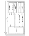
OLT1aは、図2に示すように、L2SW(レイヤ2スイッチ)11、同期クロック生成部12、監視制御部13、MPCP制御部14および複数のOSU(♯1〜y)15から構成されている。なお、予備系のOLT1bの構成は、現用系のOLT1aの構成と同様であり、その説明を省略する。また図2では、同期クロック生成部12、監視制御部13およびMPCP制御部14と、OSU♯1とを接続する信号線のみを図示しているが、その他のOSU♯2〜♯yに対しても同様に信号線が接続されている。
Next, the configuration of each part of the PON system will be described.
As shown in FIG. 2, the OLT 1a includes an L2SW (
L2SW11は、上位装置(不図示)からのデータ信号をMPCP制御部14に出力し、また、MPCP制御部14からのデータ信号を上位装置に送信するものである。
同期クロック生成部12は、OLT1a内の基準クロックを生成するものである。同期クロック生成部12により生成された基準クロックを示す信号は各機能部(監視制御部13および各OSU15)に出力される。
The
The synchronous
監視制御部13は、ローカルタイマ131を具備し、このローカルタイマ131の現在値(タイムスタンプ値)を示すローカルタイマ情報を生成するものである。なお、ローカルタイマ131は、同期クロック生成部12からの基準クロックを示す信号に応じて動作する。この監視制御部13により生成されたローカルタイマ情報は各OSU15に出力される。
The
MPCP制御部14は、各OSU15との間でデータ信号やMPCPメッセージの送受信を行い、MPCP処理を行うものである。このMPCP制御部14は、L2SW11からのデータ信号を各OSU15に出力し、各OSU15からのデータ信号をL2SW11に出力する。また、MPCP制御部14が処理するMPCPメッセージには、OLT1aからONU2に対してデータ信号の送信許可を通知するためのGATEメッセージや、ONU2からOLT1aに対して送信要求するデータ信号の蓄積量を通知するためのREPORTメッセージ(レポートフレーム情報)などがある。
The
OSU15は、スターカプラ3を介して各ONU2と接続されるものである。このOSU15は、第1の受信データ処理部151、第2の受信データ処理部152、PON−MAC部153および送信データ処理部154から構成されている。
The
第1の受信データ処理部151は、MPCP制御部14からのデータ信号を送信データ信号として送信データ処理部154に出力するものである。
第2の受信データ処理部152は、送信データ処理部154からの受信データ信号(データ信号やMPCPメッセージ)をMPCP制御部14に出力するものである。
The first reception
The second reception
PON−MAC部153は、MPCP機能を有し、また、ローカルタイマ155およびレポートメッセージ情報監視部156を具備し、ローカルタイマ155に基づいて、ONU2に対するデータ信号の送信開始時刻を設定するものである。なお、ローカルタイマ155は、同期クロック生成部12からの基準クロックを示す信号および監視制御部13からのローカルタイマ情報に応じて動作する。また、レポートメッセージ情報監視部156は、送信データ処理部154を介して各ONU2から取得したREPORTメッセージを監視する。
The PON-
送信データ処理部154は、第1の受信データ処理部151からの送信データ信号をスターカプラ3を介して各ONU2に送信し、ONU2からスターカプラ3を介して取得したデータ信号やMPCPメッセージを受信データ信号として第2の受信データ処理部152に送信するものである。また、ONU2からのREPORTメッセージはPON−MACのレポートメッセージ情報監視部156にも送信する。
また、送信データ処理部154では、MPCP制御部14から第1の受信データ処理部151を介して取得したGATEメッセージに、送信先のONU2に対応したLLID(Logical Link.ID)や、このONU2に対して設定したデータ信号の送信開始時刻および送信量情報を埋め込む。なお送信開始時刻はPON−MAC部153により設定されたものである。さらに、MPCP Local timer syncronizationシーケンス実行時には、ONU2に時刻同期を行わせるため、監視制御部13からのローカルタイマ情報をタイムシンク情報としてGATEメッセージに埋め込む。また、このシーケンス以降には、ONU2に時刻管理を行わせるため、監視制御部13からのローカルタイマ情報をGATEメッセージに埋め込む。
The transmission
In addition, the transmission
一方、ONU2は、PON−MAC部21から構成されている。このPON−MAC部21は、第1の受信データ処理部211、第2の受信データ処理部212、監視制御部213およびMPCP制御部214から構成されている。
On the other hand, the
第1の受信データ処理部211は、MPCPプロトコルに従って動作するものであり、OLT1aからのデータ信号を解析して、OLT1aからの信号の入力断(LOS)の検出を行うものである。ここで、第1の受信データ処理部211は、LOSを検出した場合には、その旨を監視制御部213に通知する。また、第1の受信データ処理部211は、OLT1aからのMPCPメッセージを解析して、ローカルタイマ情報の検出を行う。ここで、第1の受信データ処理部211は、ローカルタイマ情報を検出した場合には、その旨をローカルタイマ情報とともに監視制御部213に通知する。
The first received
第2の受信データ処理部212は、TimeSyncプロトコルに従って動作するものであり、OLT1aからのMPCPメッセージを解析して、タイムシンク情報を検出するものである。ここで、第2の受信データ処理部212は、タイムシンク情報を検出した場合には、その旨をタイムシンク情報とともに監視制御部213に通知する。
The second received
監視制御部213は、第1の受信データ処理部211からLOS検出が通知された場合に、MPCP制御部214のホールドオーバーステート処理部216に対して、ホールドオーバーステート処理(ホールドオーバー処理)の開始を指示するものである。このホールドオーバーステート処理とは、第2の受信データ処理部212で検出済みであり、MPCP制御部214に通知されているタイムシンク情報を処理停止が指示されるまで保持し、このタイムシンク情報に基づいてONU2内のローカルタイマ215の時刻管理を行う処理を示す。また、監視制御部213は、第2の受信データ処理部212からタイムシンク情報が通知された場合には、ホールドオーバーステート処理部216に対して、ホールドオーバーステート処理の停止を指示し、タイムシンク情報を通知する。また、監視制御部213は、第1の受信データ処理部211からローカルタイマ情報が通知された場合には、このローカルタイマ情報をMPCP制御部214に通知する。
The
MPCP制御部214は、保持するローカルタイマ215に基づいて、OLT1aとの間でデータ信号やMPCPメッセージの送受信を行い、MPCP処理を行うものである。このMPCP制御部214は、下位装置(不図示)からのデータ信号をスターカプラ3を介してOLT1aに出力し、OLT1aからスターカプラ3を介して取得したデータ信号を下位装置に送信する。また、MPCP制御部214は、ホールドオーバーステート処理部216も具備している。
ホールドオーバーステート処理部216は、監視制御部213による指示に従ってホールドオーバーステート処理を行うものである。ここで、ホールドオーバーステート処理部216は、監視制御部213からローカルタイマ情報が通知された場合に、ホールドオーバーステート処理中であれば、タイムスタンプドリフトエラーの検出を回避するため、ローカルタイマ情報を格納せず、ホールドオーバー処理中でなければ、ローカルタイマ情報を格納し、このローカルタイマ情報に基づくONU2内のローカルタイマ215の時刻管理を行う。
The
The hold over
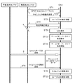
次に、上記のように構成されたPONシステムによる通信動作について説明する。
PONシステムによる通信動作では、図4に示すように、まず、現用系のOLT1a(図4のOLT“A”)とONU2との間でMPCP Discoveryシーケンスを実行する(ステップST1)。
Next, communication operation by the PON system configured as described above will be described.
In the communication operation by the PON system, as shown in FIG. 4, first, the MPCP Discovery sequence is executed between the active OLT 1a (OLT “A” in FIG. 4) and the ONU 2 (step ST1).
このMPCP Discoveryシーケンスでは、まず、OLT1aが、ONU2に対してデータ信号の送信許可を通知するためのGATEメッセージを生成して送信する。すなわち、まず、MPCP制御部14は、GATEメッセージを生成して所定のOSU15に送信する。一方、このOSU15内のPON−MAC部153は、ローカルタイマ155に基づいて、ONU2に対するデータ信号の送信開始時刻を設定する。そして、送信データ処理部154は、GATEメッセージに、ONU2に対応するLLIDやデータ信号の送信開始時刻および送信量情報、時刻同期させるためのタイムシンク情報(監視制御部13のローカルタイマ情報)を埋め込み、スターカプラ3を介して全てのONU2に送信する。
In this MPCP Discovery sequence, first, the OLT 1a generates and transmits a GATE message for notifying the
次に、GATEメッセージの送信先であるONU2は、LLIDを参照することで自機宛のGATEメッセージであることを確認した後、このGATEメッセージに対してREPORTメッセージをOLT1aに送信する。すなわち、MPCP制御部214は、送信要求するデータ信号の蓄積量情報を示すREPORTメッセージを生成する。このREPORTメッセージは、スターカプラ3を介してOLT1aに送信され、レポートメッセージ情報監視部156およびMPCP制御部14に通知される。
Next, the
次に、ONU2はデータ信号の送信を行う。すなわち、MPCP制御部214は、保持するローカルタイマ215がGATEメッセージに含まれる送信開始時刻を示した際に、GATEメッセージに含まれる送信量を上限として、データ信号をスターカプラ3を介してOLT1aに送信する。このデータ信号は、OLT1aのMPCP制御部14を介して上位装置に送信される。
Next, the
次いで、OLT1aとONU2との間で、MPCP Local timer syncronizationシーケンスを実行し、時刻同期を行う(ステップST2,3、タイムシンク情報検出ステップ,時刻同期ステップ)。すなわち、OLT1aでは、GATEメッセージをONU2に送信する際に、監視制御部13のローカルタイマ情報をタイムシンク情報としてGATEメッセージに埋め込んでいる。そしてONU2は、このGATEメッセージに含まれるタイムシンク情報が示すタイムスタンプ値に合わせて、MPCP制御部214のローカルタイマ215の現在値(タイムスタンプ値)を更新することで時刻同期を行う。
Next, the MPCP Local timer synchronization sequence is executed between the OLT 1a and the
このステップST2,3におけるシーケンスによってOLT1aとONU2との間での時刻同期が確立される(ステップST4)。これにより、各ONU2から送信されたデータ信号をスターカプラ3で多重化した際に、データ信号同士の衝突を防止することができ、OLT1aに送信することができる。
その後、ONU2とOLT1aとの間で、GATEメッセージおよびREPORTメッセージのやり取りを繰り返すことで通信を行う。またこの際、OLT1aは、ONU2に時刻管理を行わせるため、ONU2に送信するGATEメッセージに監視制御部13のローカルタイマ情報を埋め込む。そして、ONU2のMPCP制御部214は、受信したGATEメッセージに含まれるローカルタイマ情報のタイムスタンプ値に合わせて、ONU2内のローカルタイマ215のタイムスタンプ値を更新することで時刻管理を行う。また、時刻管理を行う際に、MPCP制御部214は、ローカルタイマ情報のタイムスタンプ値に対するローカルタイマ215のタイムスタンプ値のドリフト量が規定値内であるかを判断し、規定値以上の場合にはタイムスタンプドリフトエラーとして検出する。
Time synchronization between the OLT 1a and the
Thereafter, communication is performed by repeatedly exchanging the GATE message and the REPORT message between the
一方、OLT1aで障害が発生した場合(図4の符号A)、第1の受信データ処理部211は、LOSを検出して、その旨を監視制御部213に通知する(ステップST5、入力断検出ステップ)。
次いで、監視制御部213は、ホールドオーバーステート処理部216に対して、ホールドオーバーステート処理の開始を指示する(ステップST6、ホールドオーバー処理指示ステップ)。
On the other hand, when a failure occurs in the OLT 1a (symbol A in FIG. 4), the first received
Next, the
次いで、ホールドオーバーステート処理部216は、監視制御部213による指示に従って、ホールドオーバーステート処理を実行する(ステップST7、ホールドオーバー処理ステップ)。すなわち、現用系のOLT1aからの信号が入力断状態となった場合、予備系のOLT1b(図4のOLT“B”)が新たな現用系に切り替えられ、この新現用系のOLT1bとの間で時刻同期を行うまでの間は、検出済みである現用系のOLT1aからのタイムシンク情報を保持し、このタイムシンク情報に基づいてONU2内のローカルタイマ215の時刻管理を行う。
そして、ホールドオーバーステート処理中に、新現用系のOLT1bからローカルタイマ情報を含むGATEメッセージが送信された場合(図4の符号B)には、タイムスタンプドリフトエラーの検出を回避するため、このローカルタイマ情報は格納しない。
Next, the hold over
When a GATE message including local timer information is transmitted from the new
これにより、現用系のOLT1aとの間で時刻同期が行われていない新現用系OLT1bからローカルタイマ情報がONU2に送信された場合であっても、ONU2は、このローカルタイマ情報に基づいてONU2内のローカルタイマ215の時刻管理を行うことはなく、タイムスタンプドリフトエラーを検出することを回避することができる。
As a result, even when the local timer information is transmitted to the
その後、新現用系のOLT1bから時刻同期のためのタイムシンク情報を含むGATEメッセージが送信された場合(ステップST8)、第2の受信データ処理部212は、このタイムシンク情報を検出し、その旨をタイムシンク情報とともに監視制御部213に通知する(ステップST9)。
次いで、監視制御部213は、ホールドオーバーステート処理部216に対して、ホールドオーバーステート処理の停止を指示し、タイムシンク情報を通知する(ステップST10)。
After that, when a GATE message including time sync information for time synchronization is transmitted from the new
Next, the
次いで、ホールドオーバーステート処理部216は、監視制御部213による指示に従って、ホールドオーバーステート処理を停止し、タイムシンク情報のタイムスタンプ値に合わせて、ONU2内のローカルタイマ215のタイムスタンプ値を更新することで時刻同期を行う(ステップST11,12)。これにより新現用系のOLT1bとONU2との間で時刻同期を行うことができる。
その後、新現用系のOLT1bからローカルタイマ情報を含むGATEメッセージが送信され、第1の受信データ処理部211および監視制御部213を介してMPCP制御部214に通知された場合、MPCP制御部214は、このローカルタイマ情報を格納し、このローカルタイマ情報に基づいてONU2内のローカルタイマ215の時刻管理を行う。
Next, the hold over
Thereafter, when a GATE message including local timer information is transmitted from the new
以上のように、この実施の形態1によれば、ONU2は、現用系のOLT1aとの間でLOSを検出した場合に、LOS検出から新現用系のOLT1bによる新たなタイムシンク情報を検出するまでの間は、検出済みのタイムシンク情報を保持し、このタイムシンク情報に基づいてONU2内のローカルタイマ215の時刻管理を行うように構成したので、OLT1a,1bの系切り替えが発生した場合に、ONU2がタイムスタンプドリフトエラーを検出することなく、PON区間のリンクの維持を可能とすることができる。
As described above, according to the first embodiment, when the
実施の形態2.
実施の形態1では、ONU2がLOSを検出した際に、LOS検出から新たなタイムシンク情報を検出するまでの間、検出済みのタイムシンク情報を保持する場合について示したが、実施の形態2では、LOS検出から所定期間の間、検出済みのタイムシンク情報を保持することで、タイムスタンプドリフトエラーの検出を回避する場合について示す。
図5はこの発明の実施の形態2におけるONU2の構成を示す図である。図5に示す実施の形態2におけるONU2は、図3に示す実施の形態1におけるONU2のホールドオーバーステート処理部216をホールドオーバータイマ処理部217に変更したものである。その他の構成は同様であり、同一の符号を付してその説明を省略する。
In the first embodiment, when the
FIG. 5 is a diagram showing the configuration of the
なお、監視制御部213は、第1の受信データ処理部211からLOS検出が通知された場合に、MPCP制御部214のホールドオーバータイマ処理部217に対して、ホールドオーバータイマ処理(ホールドオーバー処理)の開始を指示する(図6のステップST13、ホールドオーバー処理指示ステップ)。このホールドオーバータイマ処理とは、第2の受信データ処理部212で検出済みであり、MPCP制御部214に通知されているタイムシンク情報を所定期間保持し、このタイムシンク情報に基づいてONU2内のローカルタイマ215の時刻管理を行う処理を示す。
Note that, when the LOS detection is notified from the first reception
ホールドオーバータイマ処理部217は、監視制御部213による指示に従ってホールドオーバータイマ処理を行う(図6のステップST14、ホールドオーバー処理ステップ)。ここで、ホールドオーバータイマ処理部217は、監視制御部213からローカルタイマ情報が通知された場合に、ホールドオーバータイマ処理中であれば、タイムスタンプドリフトエラーの検出を回避するため、このローカルタイマ情報を格納せず、ホールドオーバータイマ処理が満了している場合には、ローカルタイマ情報を格納し、このローカルタイマ情報に基づくONU2内のローカルタイマ215の時刻管理を行う。なお、ホールドオーバータイマ処理部217によるホールドオーバータイマ処理期間は、LOS検出から新たなシンクタイム情報を検出するのに要する期間以上に設定される。
The holdover
以上のように、この実施の形態2によれば、ONU2は、現用系のOLT1aとの間でLOSを検出した際に、LOS検出から所定期間の間は、検出済みのタイムシンク情報を保持し、このタイムシンク情報に基づいてONU2内のローカルタイマ215の時刻管理を行うように構成したので、実施の形態1と同様の効果を得ることができる。
As described above, according to the second embodiment, when the
なお、PONシステムにおける処理は1または複数のプログラムによりコンピュータ上で実現してもよく、または、その少なくとも一部をハードウェアで実現してもよい。
また、本願発明はその発明の範囲内において、各実施の形態の自由な組み合わせ、あるいは各実施の形態の任意の構成要素の変形、もしくは各実施の形態において任意の構成要素の省略が可能である。
The processing in the PON system may be realized on a computer by one or a plurality of programs, or at least a part thereof may be realized by hardware.
Further, within the scope of the present invention, the invention of the present application can be freely combined with each embodiment, modified with any component in each embodiment, or omitted with any component in each embodiment. .
1a,1b OLT(♯1,2)、2 ONU(♯11〜1z,♯21〜2z)、3 スターカプラ、11 L2SW(レイヤ2スイッチ)、12 同期クロック生成部、13 監視制御部、14 MPCP制御部、15 OSU(♯1〜y)、21 PON−MAC部、131 ローカルタイマ、151 第1の受信データ処理部、152 第2の受信データ処理部、153 PON−MAC部、154 送信データ処理部、155 ローカルタイマ、156 レポートメッセージ情報監視部、211 第1の受信データ処理部、212 第2の受信データ処理部、213 監視制御部、214 MPCP制御部、215 ローカルタイマ、216 ホールドオーバーステート処理部、217 ホールドオーバータイマ処理部。
1a, 1b OLT (# 1, 2), 2 ONU (# 11-1z, # 21-2z), 3 star coupler, 11 L2SW (
Claims (5)
現用系の前記OLTからの信号の入力断を検出する第1の受信データ処理部と、
現用系の前記OLTからの信号から、当該OLT内のローカルタイマの現在値を示すタイムシンク情報を検出する第2の受信データ処理部と、
前記第2の受信データ処理部により検出されたタイムシンク情報が示すローカルタイマの現在値に合わせて、自機内のローカルタイマの現在値を更新するMPCP制御部と、
前記第1の受信データ処理部により入力断が検出された場合に、前記MPCP制御部に対して、検出済みのタイムシンク情報を保持して、当該タイムシンク情報に基づいて自機内のローカルタイマの時刻管理を行うホールドオーバー処理の開始を指示する監視制御部とを備え、
前記MPCP制御部は、前記監視制御部からの指示に従い前記ホールドオーバー処理を行う
ことを特徴とするONU。 In an ONU that communicates with an OLT having a redundant configuration,
A first received data processing unit for detecting a disconnection of a signal from the active OLT;
A second received data processing unit for detecting time sync information indicating a current value of a local timer in the OLT from a signal from the active OLT;
An MPCP control unit that updates the current value of the local timer in the own device in accordance with the current value of the local timer indicated by the time sync information detected by the second received data processing unit;
When an input interruption is detected by the first received data processing unit, the MPCP control unit holds the detected time sync information, and based on the time sync information, A monitoring control unit for instructing start of holdover processing for performing time management,
The MPCP control unit performs the holdover process according to an instruction from the monitoring control unit.
ことを特徴とする請求項1記載のONU。 The monitoring control unit instructs the MPCP control unit to start the holdover processing when the first reception data processing unit detects an input interruption, and the second reception data processing unit 2. The ONU according to claim 1, wherein when new time sync information is detected, the MPCP control unit is instructed to stop the holdover process.
ことを特徴とする請求項1記載のONU。 The monitoring control unit instructs the MPCP control unit to perform the holdover processing for a predetermined period when an input interruption is detected by the first reception data processing unit. 1. ONU according to 1.
現用系の前記OLTからの信号から、当該OLT内のローカルタイマの現在値を示す時刻同期用のタイムシンク情報を検出するタイムシンク情報検出ステップと、
MPCP制御部により、前記タイムシンク情報検出ステップにおいて検出したタイムシンク情報が示すローカルタイマの現在値に合わせて、自機内のローカルタイマの現在値を更新する時刻同期ステップと、
現用系の前記OLTからの信号の入力断を検出する入力断検出ステップと、
前記入力断検出ステップにおいて入力断を検出した場合に、前記MPCP制御部に対して、検出済みのタイムシンク情報を保持して、当該タイムシンク情報に基づいて自機内のローカルタイマの時刻管理を行うホールドオーバー処理の開始を指示するホールドオーバー処理指示ステップと、
前記ホールドオーバーステート指示ステップにおける指示に従い、前記MPCP制御部により前記ホールドオーバー処理を行うホールドオーバー処理ステップと
を有することを特徴とする時刻同期方法。 In the time synchronization method by the ONU that communicates with the OLT having a redundant configuration,
A time sync information detecting step of detecting time sync information for time synchronization indicating a current value of a local timer in the OLT from a signal from the active OLT;
A time synchronization step of updating the current value of the local timer in the own device in accordance with the current value of the local timer indicated by the time sync information detected in the time sync information detection step by the MPCP control unit;
An input disconnection detecting step of detecting an input disconnection of a signal from the active OLT;
When an input disconnection is detected in the input disconnection detection step, the MPCP control unit holds the detected time sync information and performs time management of the local timer in the own device based on the time sync information. A holdover processing instruction step for instructing start of holdover processing;
A time synchronization method comprising: a holdover process step in which the MPCP control unit performs the holdover process according to an instruction in the holdover state instruction step.
ことを特徴とする時刻同期プログラム。 A time synchronization program for causing a computer to function as the ONU according to any one of claims 1 to 3.
Priority Applications (1)
| Application Number | Priority Date | Filing Date | Title |
|---|---|---|---|
| JP2011109518A JP2012244233A (en) | 2011-05-16 | 2011-05-16 | Onu, time synchronization method and time synchronization program |
Applications Claiming Priority (1)
| Application Number | Priority Date | Filing Date | Title |
|---|---|---|---|
| JP2011109518A JP2012244233A (en) | 2011-05-16 | 2011-05-16 | Onu, time synchronization method and time synchronization program |
Publications (1)
| Publication Number | Publication Date |
|---|---|
| JP2012244233A true JP2012244233A (en) | 2012-12-10 |
Family
ID=47465511
Family Applications (1)
| Application Number | Title | Priority Date | Filing Date |
|---|---|---|---|
| JP2011109518A Withdrawn JP2012244233A (en) | 2011-05-16 | 2011-05-16 | Onu, time synchronization method and time synchronization program |
Country Status (1)
| Country | Link |
|---|---|
| JP (1) | JP2012244233A (en) |
Cited By (4)
| Publication number | Priority date | Publication date | Assignee | Title |
|---|---|---|---|---|
| JP2014121038A (en) * | 2012-12-19 | 2014-06-30 | Nippon Telegr & Teleph Corp <Ntt> | Pon system, controller, osu and onu |
| JP2014179836A (en) * | 2013-03-15 | 2014-09-25 | Sumitomo Electric Ind Ltd | Communication system, customer premises side device, communication control method and station side device |
| JP2014236419A (en) * | 2013-06-04 | 2014-12-15 | 三菱電機株式会社 | Optical communication system, master station device, slave station device, switching control device, control device, management information acquisition method, and line switching method |
| WO2023123654A1 (en) * | 2021-12-28 | 2023-07-06 | 中兴通讯股份有限公司 | Data transmission method, apparatus, storage medium, and electronic apparatus |
-
2011
- 2011-05-16 JP JP2011109518A patent/JP2012244233A/en not_active Withdrawn
Cited By (4)
| Publication number | Priority date | Publication date | Assignee | Title |
|---|---|---|---|---|
| JP2014121038A (en) * | 2012-12-19 | 2014-06-30 | Nippon Telegr & Teleph Corp <Ntt> | Pon system, controller, osu and onu |
| JP2014179836A (en) * | 2013-03-15 | 2014-09-25 | Sumitomo Electric Ind Ltd | Communication system, customer premises side device, communication control method and station side device |
| JP2014236419A (en) * | 2013-06-04 | 2014-12-15 | 三菱電機株式会社 | Optical communication system, master station device, slave station device, switching control device, control device, management information acquisition method, and line switching method |
| WO2023123654A1 (en) * | 2021-12-28 | 2023-07-06 | 中兴通讯股份有限公司 | Data transmission method, apparatus, storage medium, and electronic apparatus |
Similar Documents
| Publication | Publication Date | Title |
|---|---|---|
| US9179204B2 (en) | Optical network system | |
| US8774621B2 (en) | Communication line switching method, communication apparatus, station-side communication apparatus, communication system, and control unit | |
| US9264213B2 (en) | Time synchronization method for communication system, slave station apparatus, master station apparatus, control device, and program | |
| EP2605427B1 (en) | Method, system and optical network unit for synchronizing data | |
| EP2779498B1 (en) | Control timing synchronization method, optical transmission system and apparatus | |
| WO2015113383A1 (en) | Channel switching method and apparatus, optical network unit and time wavelength division multiplexing system | |
| JP5546663B2 (en) | Slave station device, master station device, communication line switching method, communication system and control device | |
| JP2011135142A (en) | Transmission control system, subscriber-side transmitter, and station-side transmitter | |
| JP2012244233A (en) | Onu, time synchronization method and time synchronization program | |
| JP2012213121A (en) | Optical line terminal and communication control method in communication system | |
| JP2009065341A (en) | Pon system | |
| JP2011217298A (en) | Pon system, station-side device and terminal-side device thereof, and rtt correction method | |
| WO2011094990A1 (en) | Method and system for path switching and method for transmitting downlink data | |
| WO2013075507A1 (en) | Data sending method and system | |
| JP2018098557A (en) | Optical ring network system and redundancy method thereof | |
| JP5932627B2 (en) | PON system, controller, OSU and ONU | |
| WO2012071828A1 (en) | Method and system for transmitting data based on full protection mode in passive optical network | |
| JP5640877B2 (en) | Communication system, master station device, and communication line switching method | |
| JP6287404B2 (en) | Station side equipment | |
| JP5767183B2 (en) | PON system and link disconnection prevention method thereof | |
| JP2018098556A (en) | Optical ring network system and path control method therefor | |
| JP2011142505A (en) | Pon system, optical line terminal and optical network unit of the same, and oam link state determination method | |
| CN109391319B (en) | double-PON MAC time synchronization switching processing method and device | |
| JP5955473B2 (en) | PON system, OLT and high-speed line restoration processing method thereof | |
| JP2016086222A (en) | Network system, firmware update method, station-side termination device and subscriber-side termination device |
Legal Events
| Date | Code | Title | Description |
|---|---|---|---|
| A300 | Withdrawal of application because of no request for examination |
Free format text: JAPANESE INTERMEDIATE CODE: A300 Effective date: 20140805 |