JP2012243652A - Operation unit and electronic apparatus - Google Patents
Operation unit and electronic apparatus Download PDFInfo
- Publication number
- JP2012243652A JP2012243652A JP2011114202A JP2011114202A JP2012243652A JP 2012243652 A JP2012243652 A JP 2012243652A JP 2011114202 A JP2011114202 A JP 2011114202A JP 2011114202 A JP2011114202 A JP 2011114202A JP 2012243652 A JP2012243652 A JP 2012243652A
- Authority
- JP
- Japan
- Prior art keywords
- pressing
- pressed
- key
- operated
- operation unit
- Prior art date
- Legal status (The legal status is an assumption and is not a legal conclusion. Google has not performed a legal analysis and makes no representation as to the accuracy of the status listed.)
- Pending
Links
Images


Classifications
-
- H—ELECTRICITY
- H01—ELECTRIC ELEMENTS
- H01H—ELECTRIC SWITCHES; RELAYS; SELECTORS; EMERGENCY PROTECTIVE DEVICES
- H01H25/00—Switches with compound movement of handle or other operating part
- H01H25/04—Operating part movable angularly in more than one plane, e.g. joystick
- H01H25/041—Operating part movable angularly in more than one plane, e.g. joystick having a generally flat operating member depressible at different locations to operate different controls
-
- H—ELECTRICITY
- H01—ELECTRIC ELEMENTS
- H01H—ELECTRIC SWITCHES; RELAYS; SELECTORS; EMERGENCY PROTECTIVE DEVICES
- H01H25/00—Switches with compound movement of handle or other operating part
- H01H25/06—Operating part movable both angularly and rectilinearly, the rectilinear movement being along the axis of angular movement
- H01H25/065—Operating part movable both angularly and rectilinearly, the rectilinear movement being along the axis of angular movement using separate operating parts, e.g. a push button surrounded by a rotating knob
-
- H—ELECTRICITY
- H01—ELECTRIC ELEMENTS
- H01H—ELECTRIC SWITCHES; RELAYS; SELECTORS; EMERGENCY PROTECTIVE DEVICES
- H01H25/00—Switches with compound movement of handle or other operating part
- H01H25/04—Operating part movable angularly in more than one plane, e.g. joystick
- H01H25/041—Operating part movable angularly in more than one plane, e.g. joystick having a generally flat operating member depressible at different locations to operate different controls
- H01H2025/045—Operating part movable angularly in more than one plane, e.g. joystick having a generally flat operating member depressible at different locations to operate different controls having a rotating dial around the operating member for additional switching functions
-
- H—ELECTRICITY
- H01—ELECTRIC ELEMENTS
- H01H—ELECTRIC SWITCHES; RELAYS; SELECTORS; EMERGENCY PROTECTIVE DEVICES
- H01H25/00—Switches with compound movement of handle or other operating part
- H01H25/04—Operating part movable angularly in more than one plane, e.g. joystick
- H01H2025/048—Operating part movable angularly in more than one plane, e.g. joystick having a separate central push, slide or tumbler button which is not integral with the operating part that surrounds it
Abstract
Description
本技術は操作ユニット及び電子機器についての技術分野に関する。詳しくは、揺動キーの被押圧部が押圧操作されたときに基準軸を挟んで被押圧部の略180°反対側の位置を支点として傾斜されるようにして操作ユニットの大型化による操作性の向上及び動作の信頼性の向上を図る技術分野に関する。 The present technology relates to a technical field regarding an operation unit and an electronic device. Specifically, when the pressed portion of the rocking key is pressed, the operability is increased by increasing the size of the operation unit so that the reference portion is inclined with the position on the opposite side of the pressed portion approximately 180 ° as the fulcrum. The present invention relates to a technical field that aims to improve the reliability of the operation and operation.
記録再生装置、音声記録再生装置、音響装置、撮像装置、ネットワーク通信装置、パーソナルコンピューターやPDA(Personal Digital Assistant)等の情報処理装置等の各種の電子機器には、所定の操作を行うための操作ユニットが設けられている。 Operations for performing predetermined operations on various electronic devices such as recording / playback devices, audio recording / playback devices, acoustic devices, imaging devices, network communication devices, information processing devices such as personal computers and PDAs (Personal Digital Assistants) A unit is provided.
操作ユニットには、例えば、円板状に形成された被操作部と被操作部の中心部から突出された軸部とを有し、被操作部の外周部が押圧されることにより軸部の先端を支点として傾斜されて揺動操作されるように構成されたものがある(例えば、特許文献1参照)。 The operation unit has, for example, an operated portion formed in a disk shape and a shaft portion protruding from the center portion of the operated portion, and the outer peripheral portion of the operated portion is pressed to press the shaft portion. Some are configured to be tilted and swung with the tip as a fulcrum (see, for example, Patent Document 1).
特許文献1に記載された操作ユニットにおいては、被操作部として設けられた回動体と軸部として設けられた操作体とを有し、操作体に外方へ突出された複数のアーム部が設けられている。被操作部の外周部が押圧操作されると、全体が軸部の先端を支点として傾斜(揺動)され、アーム部の先端部によってプッシュスイッチが押圧されて所定の機能が実行される。
The operation unit described in
ところで、上記のような揺動キーを有する操作ユニットにおいては、揺動支点からアーム部の先端部までの距離に応じて操作ユニットにおいて必要な傾斜角度が定められる(図12参照)。 By the way, in the operation unit having the swing key as described above, a necessary tilt angle is determined in the operation unit according to the distance from the swing fulcrum to the tip of the arm portion (see FIG. 12).
即ち、被操作部aと軸部bとを有しアーム部c、c、・・・の先端部d、d、・・・によってそれぞれプッシュスイッチe、e、・・・が押圧される構成において、揺動操作が行われたときにアーム部cの先端部dがプッシュスイッチeを押圧するために必要な移動距離Dに基づいて傾斜角度θが定められる。 In other words, in a configuration having an operated portion a and a shaft portion b, push switches e, e,... Are pressed by the tip portions d, d,. The tilt angle θ is determined based on the moving distance D necessary for the tip portion d of the arm portion c to press the push switch e when the swing operation is performed.
傾斜角度θは移動距離Dの長さに応じて大きくなるが、傾斜角度θが大きくなると移動距離Dに直交する方向における変位量Hが大きくなり、被操作部aが押圧操作されたときに被操作部aの外周部fが操作ユニットにおける他の部分gに接触し易くなり、操作性が低下するおそれがある。 The inclination angle θ increases according to the length of the movement distance D. However, when the inclination angle θ increases, the displacement amount H in the direction orthogonal to the movement distance D increases, and when the operated portion a is pressed, the inclination angle θ is increased. The outer peripheral part f of the operation part a tends to come into contact with another part g in the operation unit, and the operability may be reduced.
一方、操作性の向上を図るためには被操作部aの大きさを軸部bに直交する方向(移動距離Dに直交する方向)に大型化することが好ましいが、被操作部aが大きくなると、揺動操作が行われたときに被操作部aの外周部fが他の部分hに接触し易くなる。従って、被操作部aの外周部fの他の部分hに対する接触を防止するためには、傾斜角度θを小さくすることが望ましいが、傾斜角度θを小さくするとプッシュスイッチeを押圧するために必要な移動距離Dを確保することができなくなるおそれがあり、動作の信頼性が低下してしまう。 On the other hand, in order to improve the operability, it is preferable to increase the size of the operated portion a in a direction orthogonal to the shaft portion b (direction orthogonal to the movement distance D), but the operated portion a is large. As a result, when the swing operation is performed, the outer peripheral portion f of the operated portion a easily comes into contact with the other portion h. Therefore, in order to prevent contact with the other part h of the outer peripheral part f of the operated part a, it is desirable to reduce the inclination angle θ, but it is necessary to press the push switch e when the inclination angle θ is reduced. It may not be possible to secure a sufficient moving distance D, and the reliability of the operation is lowered.
そこで、本技術操作ユニット及び電子機器は、上記した問題点を克服し、操作ユニットの大型化による操作性の向上及び動作の信頼性の向上を図ることを課題とする。 Therefore, it is an object of the present technology operation unit and electronic device to overcome the above-described problems, and to improve operability and operational reliability by increasing the size of the operation unit.
操作ユニットは、上記した課題を解決するために、所定の基準軸を中心として回転されて操作される回転ダイヤルと、前記回転ダイヤルの内側に配置されると共に押圧操作される被押圧部が形成された被操作部を有し前記被押圧部が押圧されて前記基準軸に対して傾斜されて操作される揺動キーと、前記揺動キーが操作されたときに押圧されて操作信号を出力するプッシュスイッチとを備え、前記揺動キーは前記被押圧部が押圧操作されたときに前記基準軸を挟んで前記被押圧部の略180°反対側の位置を支点として傾斜されるようにしたものである。 In order to solve the above-described problems, the operation unit is formed with a rotary dial that is rotated and operated around a predetermined reference axis, and a pressed portion that is disposed inside the rotary dial and that is pressed. A swing key that is operated by being tilted with respect to the reference axis when the pressed portion is pressed and an operation signal that is pressed when the swing key is operated. A push switch, and the swing key is tilted with a position on the opposite side of the pressed portion approximately 180 ° across the reference shaft when the pressed portion is pressed. It is.
従って、操作ユニットにあっては、基準軸を挟んで被押圧部の略180°反対側の位置を支点として傾斜されてプッシュスイッチが押圧される。 Therefore, in the operation unit, the push switch is pressed while being tilted with the position on the opposite side of the pressed portion approximately 180 ° across the reference shaft as a fulcrum.
第2に、上記した操作ユニットにおいては、前記揺動キーに前記被押圧部が複数設けられ、前記複数の被押圧部が周方向に離隔して位置されることが望ましい。 Second, in the operation unit described above, it is desirable that a plurality of the pressed parts are provided on the swing key, and the plurality of pressed parts are spaced apart in the circumferential direction.
揺動キーに被押圧部が複数設けられ、複数の被押圧部が周方向に離隔して位置されることにより、一つの揺動キーによって複数の異なる操作が可能になる。 A plurality of pressed portions are provided on the swing key, and the plurality of pressed portions are spaced apart in the circumferential direction, so that a plurality of different operations can be performed with one swing key.
第3に、上記した操作ユニットにおいては、前記回転ダイヤルに配置用凹部が形成され、前記回転ダイヤルの中央部に前記配置用凹部に連通された配置孔が形成され、前記配置孔に前記プッシュスイッチが配置され、前記配置用凹部に前記配置孔を覆う状態で前記揺動キーが配置されることが望ましい。 Thirdly, in the above-described operation unit, an arrangement recess is formed in the rotary dial, an arrangement hole communicating with the arrangement recess is formed in a central portion of the rotation dial, and the push switch is formed in the arrangement hole. It is desirable that the rocking key is disposed in a state in which the arrangement hole is covered with the arrangement recess.
回転ダイヤルの配置用凹部に配置孔を覆う状態で揺動キーが配置されることにより、揺動キーによって配置孔に配置されたプッシュスイッチへの塵埃の付着が低減される。 By disposing the swing key in a state where the disposition recess of the rotary dial covers the disposition hole, the adhesion of dust to the push switch disposed in the disposition hole by the swing key is reduced.
第4に、上記した操作ユニットにおいては、前記回転ダイヤルの内部に前記基準軸を中心とした周方向に延びる配置スペースが形成され、前記回転ダイヤルに前記基準軸を中心とした周方向に延びるギヤ部が形成され、前記配置スペースにエンコーダーの少なくとも一部が配置され、前記エンコーダーに前記ギヤ部と噛合された回転ギヤが設けられることが望ましい。 Fourth, in the operation unit described above, an arrangement space extending in the circumferential direction around the reference axis is formed inside the rotary dial, and a gear extending in the circumferential direction around the reference axis is formed in the rotary dial. It is preferable that a part is formed, at least a part of the encoder is arranged in the arrangement space, and a rotary gear meshed with the gear part is provided in the encoder.
回転ダイヤルに基準軸を中心とした周方向に延びるギヤ部が形成され、配置スペースにエンコーダーの少なくとも一部が配置され、エンコーダーにギヤ部と噛合された回転ギヤが設けられることにより、配置スペースに配置されたエンコーダーの回転ギヤが回転ダイヤルの回転に伴って回転される。 A gear portion extending in the circumferential direction around the reference axis is formed on the rotary dial, and at least a part of the encoder is arranged in the arrangement space, and the rotation gear meshed with the gear portion is provided in the arrangement space. The rotary gear of the arranged encoder is rotated with the rotation of the rotary dial.
第5に、上記した操作ユニットにおいては、前記回転ダイヤルに、外周部と、前記外周部の内側に前記外周部と離隔して位置する内周部と、前記外周部の一端部と前記内周部の一端部とを連結する連結部とが設けられ、前記内周部に前記ギヤ部が形成され、前記外周部と前記内周部の間に前記配置スペースが形成されることが望ましい。 Fifth, in the above-described operation unit, the rotary dial includes an outer peripheral portion, an inner peripheral portion located on the inner side of the outer peripheral portion and spaced apart from the outer peripheral portion, one end portion of the outer peripheral portion, and the inner peripheral portion. It is desirable that a connecting portion for connecting one end portion of the portion is provided, the gear portion is formed on the inner peripheral portion, and the arrangement space is formed between the outer peripheral portion and the inner peripheral portion.
回転ダイヤルに外周部と内周部と連結部とが設けられ、内周部にギヤ部が形成され、外周部と内周部の間に配置スペースが形成されることにより、配置スペースに配置されたエンコーダーの回転ギヤに回転ダイヤルのギヤ部が噛合される。 An outer peripheral portion, an inner peripheral portion, and a connecting portion are provided on the rotary dial, a gear portion is formed on the inner peripheral portion, and an arrangement space is formed between the outer peripheral portion and the inner peripheral portion, thereby being arranged in the arrangement space. The gear portion of the rotary dial is meshed with the rotary gear of the encoder.
第6に、上記した操作ユニットにおいては、前記揺動キーの中央部に挿入配置孔が形成され、前記挿入配置孔に、押圧されて操作される押圧キーが配置され、前記押圧キーが操作されたときに押圧されて操作信号を出力するプッシュスイッチが配置されることが望ましい。 Sixth, in the operation unit described above, an insertion arrangement hole is formed at the center of the swing key, a pressing key that is operated by being pressed is arranged in the insertion arrangement hole, and the pressing key is operated. It is desirable that a push switch that is pressed to output an operation signal is disposed.
揺動キーの中央部に形成された挿入配置孔に押圧キーが配置され、押圧キーが操作されたときに押圧されて操作信号を出力するプッシュスイッチが配置されることにより、回転ダイヤルの内側に揺動キーと押圧キーが配置される。 A push key is placed in the insertion placement hole formed in the center of the swing key, and a push switch that is pressed to output an operation signal when the push key is operated is placed inside the rotary dial. A swing key and a press key are arranged.
第7に、上記した操作ユニットにおいては、前記揺動キーは押圧操作される前の非操作位置と前記プッシュスイッチを押圧する操作位置との間で移動され、押圧操作が解除されたときに前記揺動キーを前記操作位置から前記非操作位置に戻す弾性変形可能な弾性部材を設け、前記弾性部材として前記基準軸の軸方向を向くシート状のゴム部材を用いることが望ましい。 Seventh, in the operation unit described above, the swing key is moved between a non-operation position before being pressed and an operation position for pressing the push switch, and when the pressing operation is released, It is preferable that an elastically deformable elastic member for returning the swing key from the operation position to the non-operation position is provided, and a sheet-like rubber member facing the axial direction of the reference shaft is used as the elastic member.
揺動キーは押圧操作される前の非操作位置と前記プッシュスイッチを押圧する操作位置との間で移動され、揺動キーを操作位置から非操作位置に戻す弾性変形可能な弾性部材として基準軸の軸方向を向くシート状のゴム部材を用いることにより、押圧操作時に揺動キーにゴム部材によって操作位置から非操作位置へ向けての付勢力が付与される。 The swing key is moved between a non-operation position before being pressed and an operation position for pressing the push switch, and is a reference shaft as an elastically deformable elastic member that returns the swing key from the operation position to the non-operation position. By using the sheet-like rubber member facing the axial direction, an urging force from the operation position to the non-operation position is applied to the swing key by the rubber member during the pressing operation.
第8に、上記した操作ユニットにおいては、前記押圧キーは押圧操作される前の初期位置と前記プッシュスイッチを押圧する押圧位置との間で移動され、押圧操作が解除されたときに前記押圧キーを前記押圧位置から前記初期位置に戻す弾性変形可能な弾性部材を設け、前記弾性部材として前記基準軸の軸方向を向くシート状のゴム部材を用いることが望ましい。 Eighth, in the operation unit described above, the pressing key is moved between an initial position before the pressing operation and a pressing position for pressing the push switch, and the pressing key is released when the pressing operation is released. It is preferable to provide an elastically deformable elastic member that returns the pressure from the pressing position to the initial position, and a sheet-like rubber member that faces the axial direction of the reference shaft is used as the elastic member.
押圧キーは押圧操作される前の初期位置とプッシュスイッチを押圧する押圧位置との間で移動され、押圧キーを押圧位置から初期位置に戻す弾性変形可能な弾性部材として基準軸の軸方向を向くシート状のゴム部材を用いることにより、押圧操作時に押圧キーにゴム部材によって押圧位置から初期位置へ向けての付勢力が付与される。 The pressing key is moved between the initial position before the pressing operation and the pressing position for pressing the push switch, and faces the axial direction of the reference shaft as an elastically deformable elastic member that returns the pressing key from the pressing position to the initial position. By using the sheet-like rubber member, an urging force from the pressing position toward the initial position is applied to the pressing key by the rubber member during the pressing operation.
第9に、上記した操作ユニットにおいては、前記揺動キーの中央部に挿入配置孔が形成され、前記挿入配置孔に、押圧されて操作される押圧キーが配置され、前記押圧キーが操作されたときに押圧されて操作信号を出力するプッシュスイッチが配置され、前記押圧キーは押圧操作される前の初期位置と前記プッシュスイッチを押圧する押圧位置との間で移動され、押圧操作が解除されたときに前記押圧キーを前記操作位置から前記非操作位置に戻す弾性変形可能な弾性部材として前記ゴム部材を用いることが望ましい。 Ninth, in the above-described operation unit, an insertion arrangement hole is formed in the central portion of the swing key, a press key operated by being pressed is arranged in the insertion arrangement hole, and the press key is operated. A push switch that is pressed to output an operation signal is disposed, and the push key is moved between an initial position before the push operation and a push position that pushes the push switch, and the push operation is released. Preferably, the rubber member is used as an elastically deformable elastic member that returns the pressing key from the operating position to the non-operating position.
揺動キーの中央部に形成された挿入配置孔に押圧キーが配置され、押圧キーを押圧位置から初期位置に戻す弾性変形可能な弾性部材として基準軸の軸方向を向くシート状のゴム部材を用いることにより、押圧操作時に押圧キーにゴム部材によって押圧位置から初期位置へ向けての付勢力が付与される。 A sheet-like rubber member facing the axial direction of the reference axis is provided as an elastically deformable elastic member in which a pressing key is disposed in an insertion hole formed in the central portion of the swing key, and the pressing key is returned from the pressing position to the initial position. By using it, an urging force from the pressing position toward the initial position is applied to the pressing key by the rubber member during the pressing operation.
第10に、上記した操作ユニットにおいては、前記揺動キーは押圧操作される前の非操作位置と押圧操作されたときの操作位置との間で移動され、押圧操作が解除されたときに前記揺動キーを前記操作位置から前記非操作位置に戻す弾性変形可能な弾性部材を設け、前記弾性部材として前記基準軸の軸方向において伸縮される圧縮コイルバネを用いることが望ましい。 Tenth, in the operation unit described above, the rocking key is moved between the non-operation position before the pressing operation and the operation position when the pressing operation is performed, and the pressing operation is released when the pressing operation is released. It is desirable to provide an elastically deformable elastic member that returns the swing key from the operating position to the non-operating position, and a compression coil spring that is expanded and contracted in the axial direction of the reference shaft is used as the elastic member.
揺動キーは押圧操作される前の非操作位置と押圧操作されたときの操作位置との間で移動され、揺動キーを操作位置から非操作位置に戻す弾性変形可能な弾性部材として基準軸の軸方向において伸縮される圧縮コイルバネを用いることにより、揺動キーに圧縮コイルバネによって操作位置から非操作位置へ向けての付勢力が付与される。 The swing key is moved between a non-operation position before the pressing operation and an operation position when the pressing operation is performed, and the reference shaft serves as an elastically deformable elastic member that returns the swing key from the operation position to the non-operation position. By using a compression coil spring that is expanded and contracted in the axial direction, an urging force from the operation position to the non-operation position is applied to the swing key by the compression coil spring.
第11に、上記した操作ユニットにおいては、前記押圧キーは押圧操作される前の初期位置と前記プッシュスイッチを押圧する押圧位置との間で移動され、押圧操作が解除されたときに前記押圧キーを前記押圧位置から前記初期位置に戻す弾性変形可能な弾性部材を設け、前記弾性部材として前記基準軸の軸方向において伸縮される圧縮コイルバネを用いることが望ましい。 Eleventh, in the above-described operation unit, the pressing key is moved between an initial position before the pressing operation and a pressing position for pressing the push switch, and the pressing key is released when the pressing operation is released. It is desirable to provide an elastically deformable elastic member that returns the pressure from the pressing position to the initial position, and a compression coil spring that is expanded and contracted in the axial direction of the reference shaft is used as the elastic member.
押圧キーは押圧操作される前の初期位置とプッシュスイッチを押圧する押圧位置との間で移動され、押圧キーを押圧位置から初期位置に戻す弾性変形可能な弾性部材として基準軸の軸方向において伸縮される圧縮コイルバネを用いることにより、押圧キーに圧縮コイルバネによって押圧位置から初期位置へ向けての付勢力が付与される。 The pressing key is moved between the initial position before the pressing operation and the pressing position for pressing the push switch, and is expanded and contracted in the axial direction of the reference shaft as an elastically deformable elastic member that returns the pressing key from the pressing position to the initial position. By using the compressed coil spring, the pressing key is applied with an urging force from the pressed position to the initial position by the compressed coil spring.
第12に、上記した操作ユニットにおいては、前記揺動キーの中央部に挿入配置孔が形成され、前記挿入配置孔に、押圧されて操作される押圧キーが配置され、前記押圧キーが操作されたときに押圧されて操作信号を出力するプッシュスイッチが配置され、前記押圧キーは押圧操作される前の初期位置と前記プッシュスイッチを押圧する押圧位置との間で移動され、押圧操作が解除されたときに前記押圧キーを前記押圧位置から前記初期位置に戻す弾性変形可能な弾性部材を設け、前記弾性部材として前記基準軸の軸方向において伸縮される圧縮コイルバネを用い、前記揺動キーを前記操作位置から前記非操作位置に戻す前記圧縮コイルバネと前記押圧キーを前記押圧位置から前記初期位置に戻す圧縮コイルバネとを同軸上に配置することが望ましい。 12thly, in the above-mentioned operation unit, an insertion arrangement hole is formed in the central part of the rocking key, a press key operated by being pressed is arranged in the insertion arrangement hole, and the press key is operated. A push switch that is pressed to output an operation signal is disposed, and the push key is moved between an initial position before the push operation and a push position that pushes the push switch, and the push operation is released. An elastic member that is elastically deformable to return the pressing key from the pressing position to the initial position, and a compression coil spring that expands and contracts in the axial direction of the reference shaft is used as the elastic member. The compression coil spring that returns the operation position to the non-operation position and the compression coil spring that returns the pressing key from the pressing position to the initial position may be arranged coaxially. Masui.
揺動キーを操作位置から非操作位置に戻す圧縮コイルバネと押圧キーを押圧位置から初期位置に戻す圧縮コイルバネとを同軸上に配置することにより、弾性部材の配置スペースが小さくなる。 By arranging the compression coil spring that returns the swing key from the operating position to the non-operating position and the compression coil spring that returns the pressing key from the pressed position to the initial position, the arrangement space of the elastic member is reduced.
電子機器は、上記した課題を解決するために、操作ユニットと前記操作ユニットに対する操作に応じて動作される本体とを備え、前記操作ユニットが、所定の基準軸を中心として回転されて操作される回転ダイヤルと、前記回転ダイヤルの内側に配置されると共に押圧操作される被押圧部が形成された被操作部を有し前記被押圧部が押圧されて前記基準軸に対して傾斜されて操作される揺動キーと、前記揺動キーが操作されたときに押圧されて操作信号を出力するプッシュスイッチとを備え、前記揺動キーは前記被押圧部が押圧操作されたときに前記基準軸を挟んで前記被押圧部の略180°反対側の位置を支点として傾斜されるようにしたものである。 In order to solve the above-described problem, the electronic apparatus includes an operation unit and a main body that is operated in response to an operation on the operation unit, and the operation unit is operated by being rotated around a predetermined reference axis. A rotating dial and an operated portion that is disposed inside the rotating dial and has a pressed portion that is pressed is formed. The pressed portion is pressed and tilted with respect to the reference axis. A swing key that is pressed when the swing key is operated and outputs an operation signal, and the swing key moves the reference shaft when the pressed portion is pressed. Inclined with the position on the opposite side of the pressed part approximately 180 ° between the nips.
従って、電子機器にあっては、基準軸を挟んで被押圧部の略180°反対側の位置を支点として傾斜されてプッシュスイッチが押圧される。 Therefore, in the electronic device, the push switch is pressed while being tilted with the position on the opposite side of the pressed portion approximately 180 ° across the reference axis as a fulcrum.
本技術操作ユニットは、所定の基準軸を中心として回転されて操作される回転ダイヤルと、前記回転ダイヤルの内側に配置されると共に押圧操作される被押圧部が形成された被操作部を有し前記被押圧部が押圧されて前記基準軸に対して傾斜されて操作される揺動キーと、前記揺動キーが操作されたときに押圧されて操作信号を出力するプッシュスイッチとを備え、前記揺動キーは前記被押圧部が押圧操作されたときに前記基準軸を挟んで前記被押圧部の略180°反対側の位置を支点として傾斜されるようにしている。 The operation unit of the present technology includes a rotary dial that is operated by being rotated about a predetermined reference axis, and an operated part that is disposed inside the rotary dial and has a pressed part that is pressed. A swing key that is operated by being pushed with respect to the reference axis and being tilted with respect to the reference axis; and a push switch that is pressed to output an operation signal when the swing key is operated, The swing key is tilted with a position on the opposite side of the pressed part approximately 180 ° across the reference axis when the pressed part is pressed.
従って、操作ユニットを大型化したときにおいても揺動キーの揺動時に被操作部が操作ユニットの他の部分に接触し難く、操作ユニットの大型化による操作性の向上及び動作の信頼性の向上を図ることができる。 Therefore, even when the operation unit is increased in size, the operated part is difficult to come into contact with other parts of the operation unit when the swing key is swung, and the operability is improved and the operation reliability is improved by increasing the size of the operation unit. Can be achieved.
請求項2に記載した技術にあっては、前記揺動キーに前記被押圧部が複数設けられ、前記複数の被押圧部が周方向に離隔して位置されている。 According to a second aspect of the present invention, a plurality of the pressed parts are provided on the swing key, and the plurality of pressed parts are spaced apart in the circumferential direction.
従って、一つの揺動キーによって複数の異なる操作が可能であり、操作ユニットの操作性の向上を図ることができる。 Therefore, a plurality of different operations can be performed with one swing key, and the operability of the operation unit can be improved.
請求項3に記載した技術にあっては、前記回転ダイヤルに配置用凹部が形成され、前記回転ダイヤルの中央部に前記配置用凹部に連通された配置孔が形成され、前記配置孔に前記プッシュスイッチが配置され、前記配置用凹部に前記配置孔を覆う状態で前記揺動キーが配置されている。
In the technique according to
従って、揺動キーによって配置孔からの塵埃の侵入が抑制され、配置孔に配置されたプッシュスイッチへの塵埃の付着が低減され、動作の信頼性の向上を図ることができる。 Therefore, the intrusion of dust from the arrangement hole is suppressed by the swing key, the adhesion of dust to the push switch arranged in the arrangement hole is reduced, and the operation reliability can be improved.
請求項4に記載した技術にあっては、前記回転ダイヤルの内部に前記基準軸を中心とした周方向に延びる配置スペースが形成され、前記回転ダイヤルに前記基準軸を中心とした周方向に延びるギヤ部が形成され、前記配置スペースにエンコーダーの少なくとも一部が配置され、前記エンコーダーに前記ギヤ部と噛合された回転ギヤが設けられている。 In the technique according to claim 4, an arrangement space extending in the circumferential direction around the reference axis is formed inside the rotary dial, and the rotary dial extends in the circumferential direction around the reference axis. A gear part is formed, at least a part of the encoder is arranged in the arrangement space, and a rotating gear meshed with the gear part is provided in the encoder.
従って、スペースの有効活用を図ることができると共にエンコーダーが揺動される構成とされておらずエンコーダーに対する負荷の軽減を図ることができる。 Therefore, it is possible to effectively use the space and reduce the load on the encoder because the encoder is not configured to be swung.
請求項5に記載した技術にあっては、前記回転ダイヤルに、外周部と、前記外周部の内側に前記外周部と離隔して位置する内周部と、前記外周部の一端部と前記内周部の一端部とを連結する連結部とが設けられ、前記内周部に前記ギヤ部が形成され、前記外周部と前記内周部の間に前記配置スペースが形成されている。
In the technique described in
従って、回転ダイヤルの構造の簡素化を図った上で配置スペースの有効活用を図ることができる。 Accordingly, the arrangement space can be effectively utilized after the structure of the rotary dial is simplified.
請求項6に記載した技術にあっては、前記揺動キーの中央部に挿入配置孔が形成され、前記挿入配置孔に、押圧されて操作される押圧キーが配置され、前記押圧キーが操作されたときに押圧されて操作信号を出力するプッシュスイッチが配置されている。 In the technique described in claim 6, an insertion arrangement hole is formed in a central portion of the swing key, a pressing key operated by being pressed is arranged in the insertion arrangement hole, and the pressing key is operated. A push switch is arranged that is pressed to output an operation signal.
従って、回転ダイヤル、押圧キー及び揺動キーの三つの操作部を有する操作ユニットを簡素な構造によって構成することができる。 Therefore, the operation unit having the three operation portions of the rotary dial, the pressing key, and the swing key can be configured with a simple structure.
請求項7に記載した技術にあっては、前記揺動キーは押圧操作される前の非操作位置と前記プッシュスイッチを押圧する操作位置との間で移動され、押圧操作が解除されたときに前記揺動キーを前記操作位置から前記非操作位置に戻す弾性変形可能な弾性部材を設け、前記弾性部材として前記基準軸の軸方向を向くシート状のゴム部材を用いている。
In the technique described in
従って、弾性部材の配置スペースが小さくて済み、操作ユニットの構造の簡素化及び操作ユニットの軸方向における薄型化を図ることができる。 Therefore, the space for disposing the elastic member is small, and the structure of the operation unit can be simplified and the operation unit can be thinned in the axial direction.
請求項8に記載した技術にあっては、前記押圧キーは押圧操作される前の初期位置と前記プッシュスイッチを押圧する押圧位置との間で移動され、押圧操作が解除されたときに前記押圧キーを前記押圧位置から前記初期位置に戻す弾性変形可能な弾性部材を設け、前記弾性部材として前記基準軸の軸方向を向くシート状のゴム部材を用いている。
In the technique described in
従って、弾性部材の配置スペースが小さくて済み、操作ユニットの構造の簡素化及び操作ユニットの軸方向における薄型化を図ることができる。 Therefore, the space for disposing the elastic member is small, and the structure of the operation unit can be simplified and the operation unit can be thinned in the axial direction.
請求項9に記載した技術にあっては、前記揺動キーの中央部に挿入配置孔が形成され、前記挿入配置孔に、押圧されて操作される押圧キーが配置され、前記押圧キーが操作されたときに押圧されて操作信号を出力するプッシュスイッチが配置され、前記押圧キーは押圧操作される前の初期位置と前記プッシュスイッチを押圧する押圧位置との間で移動され、押圧操作が解除されたときに前記押圧キーを前記操作位置から前記非操作位置に戻す弾性変形可能な弾性部材として前記ゴム部材を用いている。
In the technique according to
従って、操作ユニットの部品点数の削減及び機構の簡素化を図ることができる。 Therefore, the number of parts of the operation unit can be reduced and the mechanism can be simplified.
請求項10に記載した技術にあっては、前記揺動キーは押圧操作される前の非操作位置と押圧操作されたときの操作位置との間で移動され、押圧操作が解除されたときに前記揺動キーを前記操作位置から前記非操作位置に戻す弾性変形可能な弾性部材を設け、前記弾性部材として前記基準軸の軸方向において伸縮される圧縮コイルバネを用いている。
In the technique described in
従って、操作ユニットの構造の簡素化及び製造コストの低減を図ることができる。 Therefore, the structure of the operation unit can be simplified and the manufacturing cost can be reduced.
請求項11に記載した技術にあっては、前記押圧キーは押圧操作される前の初期位置と前記プッシュスイッチを押圧する押圧位置との間で移動され、押圧操作が解除されたときに前記押圧キーを前記押圧位置から前記初期位置に戻す弾性変形可能な弾性部材を設け、前記弾性部材として前記基準軸の軸方向において伸縮される圧縮コイルバネを用いている。
In the technique described in
従って、操作ユニットの構造の簡素化及び製造コストの低減を図ることができる。 Therefore, the structure of the operation unit can be simplified and the manufacturing cost can be reduced.
請求項12に記載した技術にあっては、前記揺動キーの中央部に挿入配置孔が形成され、前記挿入配置孔に、押圧されて操作される押圧キーが配置され、前記押圧キーが操作されたときに押圧されて操作信号を出力するプッシュスイッチが配置され、前記押圧キーは押圧操作される前の初期位置と前記プッシュスイッチを押圧する押圧位置との間で移動され、押圧操作が解除されたときに前記押圧キーを前記押圧位置から前記初期位置に戻す弾性変形可能な弾性部材を設け、前記弾性部材として前記基準軸の軸方向において伸縮される圧縮コイルバネを用い、前記揺動キーを前記操作位置から前記非操作位置に戻す前記圧縮コイルバネと前記押圧キーを前記押圧位置から前記初期位置に戻す圧縮コイルバネとを同軸上に配置している。
In the technique described in
従って、スペース効率の向上による操作ユニット7の軸方向における薄型化を図ることができる。
Therefore, it is possible to reduce the thickness of the
本技術電子機器は、操作ユニットと前記操作ユニットに対する操作に応じて動作される本体とを備え、前記操作ユニットが、所定の基準軸を中心として回転されて操作される回転ダイヤルと、前記回転ダイヤルの内側に配置されると共に押圧操作される被押圧部が形成された被操作部を有し前記被押圧部が押圧されて前記基準軸に対して傾斜されて操作される揺動キーと、前記揺動キーが操作されたときに押圧されて操作信号を出力するプッシュスイッチとを備え、前記揺動キーは前記被押圧部が押圧操作されたときに前記基準軸を挟んで前記被押圧部の略180°反対側の位置を支点として傾斜されるようにしている。 An electronic apparatus according to an embodiment of the present technology includes an operation unit and a main body that is operated according to an operation on the operation unit, and the operation unit is operated by being rotated around a predetermined reference axis; and the rotation dial A swing key that is disposed on the inside and has a portion to be pressed that is operated to be pressed, and is operated while being tilted with respect to the reference axis by pressing the portion to be pressed. A push switch that is pressed when the swing key is operated and outputs an operation signal, and the swing key sandwiches the reference shaft when the pressed portion is pressed. It is inclined with the position on the opposite side of about 180 ° as a fulcrum.
従って、操作ユニットを大型化したときにおいても揺動キーの揺動時に被操作部が操作ユニットの他の部分に接触し難く、電子機器において、操作ユニットの大型化による操作性の向上及び動作の信頼性の向上を図ることができる。 Therefore, even when the size of the operation unit is increased, it is difficult for the operated part to come into contact with other parts of the operation unit when the swing key is swung. Reliability can be improved.
以下に、本技術操作ユニット及び電子機器を実施するための最良の形態を添付図面に従って説明する。 The best mode for carrying out the operation unit and the electronic apparatus according to the present technology will be described below with reference to the accompanying drawings.
以下に示した最良の形態は、本技術電子機器をスピーカーを有する音響装置に適用し、本技術操作ユニットをこの音響装置に設けられた操作ユニットに適用したものである。 In the best mode described below, the electronic device of the present technology is applied to an audio device having a speaker, and the operation unit of the present technology is applied to an operation unit provided in the audio device.
但し、本技術の適用範囲は音響装置及びこれに設けられた操作ユニットに限られることはない。本技術電子機器は、ディスク記録再生装置等の記録媒体を用いる記録再生装置、音声の記録や再生を行う音声記録再生装置、画像や映像を撮影する撮像装置、一方向又は双方向の送受信を行うネットワーク通信装置、パーソナルコンピューターやPDA(Personal Digital Assistant)等の情報処理装置等の他の各種の電子機器に広く適用することができる。また、本技術操作ユニットは、これらの各種の電子機器に設けられた操作ユニットに広く適用することができる。 However, the application range of the present technology is not limited to the acoustic device and the operation unit provided in the acoustic device. The electronic apparatus according to an embodiment of the present technology performs a recording / reproducing apparatus using a recording medium such as a disk recording / reproducing apparatus, an audio recording / reproducing apparatus that records and reproduces audio, an imaging apparatus that captures images and videos, and performs one-way or two-way transmission / reception. The present invention can be widely applied to other various electronic devices such as network communication devices, information processing devices such as personal computers and PDAs (Personal Digital Assistants). The operation unit of the present technology can be widely applied to operation units provided in these various electronic devices.
以下の説明にあっては、スピーカーが向く方向を前方として前後上下左右の方向を示すものとする。尚、以下に示す前後上下左右の方向は説明の便宜上のものであり、本技術の実施に関しては、これらの方向に限定されることはない。 In the following description, the direction in which the speaker faces is assumed to be the front, and the front, rear, up, down, left and right directions are indicated. In addition, the following directions of front and rear, up, down, left, and right shown below are for convenience of explanation, and the implementation of the present technology is not limited to these directions.
[電子機器の概略構成]
電子機器(音響装置)1は、図1に示すように、本体2と本体2の左右に配置された一対のスピーカーユニット3、3によって構成されている。スピーカーユニット3、3にはそれぞれ上下に離隔して音声出力部3a、3a、・・・が設けられており、音声出力部3a、3a、・・・からそれぞれ所定の帯域の音声が出力される。
[Schematic configuration of electronic equipment]
As shown in FIG. 1, the electronic apparatus (acoustic device) 1 includes a
本体2は筐体4に所要の各部が配置されて成る。
The
筐体4の上端部にはトレイ5が前後方向へ移動自在に支持されている。トレイ5は筐体4に収納される位置と筐体4から引き出される位置との間で移動可能とされている。筐体4からトレイ5が引き出された状態においては図示しない記録ディスクの装着が可能とされ、記録ディスクが装着されたトレイ5が筐体4に収納されると、記録ディスクに記録された音楽データーの再生が可能とされている。
A
筐体4の前面には表示部6が設けられている。表示部6には電子機器1の現在の動作状態や後述する操作ユニットの操作状態等が表示される。
A display unit 6 is provided on the front surface of the housing 4. The display unit 6 displays a current operation state of the
[操作ユニットの構成]
以下に、操作ユニットの第1の実施の形態について説明する(図1乃至図7参照)。
[Operation unit configuration]
Hereinafter, a first embodiment of the operation unit will be described (see FIGS. 1 to 7).
筐体4の前面における中央部には操作ユニット7が配置されている。操作ユニット7は前後方向を向くベース板8に所要の各部が配置されて成る(図2乃至図4参照)。
An
ベース板8は外形が円形状に形成され、円環状の外側部9と外側部9の内側に位置する内側部10とによって構成されている。
The
内側部10は円環状の突部11と突部11の内側に位置する中央部12とから成る。突部11は外側部9より稍前側に位置され、中央部12は外側部9と同一平面上に位置されている。突部11には挿通配置孔11aが形成されている。中央部12には十字状のスイッチ配置孔12aが形成されている。
The
ベース板8における中央部12の外周部の前面は取付面8aとして形成され、取付面8aの外側に連続する部分の前面が摺動面8bとして形成されている。摺動面8bは取付面8aより前方に位置されている。
The front surface of the outer peripheral portion of the
ベース板8の後面には回路基板13が取り付けられている。回路基板13の前面にはエンコーダー14とプッシュスイッチ15、15、・・・が搭載されている。
A
エンコーダー14は回路基板13に取り付けられた基体部16と基体部16から前方へ突出された回転軸17と回転軸17に取り付けられた回転ギヤ18とを有している。回転ギヤ18は円筒状の被取付部18aと被取付部18aから外方に張り出されたギヤ部18bとから成り、被取付部18aが回転軸17に嵌合されて取り付けられている。
The
エンコーダー14は回路基板13の外周部に搭載され、ベース板8の挿通配置孔11aに配置され回転ギヤ18がベース板8の前方に位置されている。
The
プッシュスイッチ15、15、・・・は回路基板13の中央部とその上下左右に並ぶようにして搭載されている。プッシュスイッチ15、15、・・・は、ベース板8のスイッチ配置孔12aに配置されている。
The push switches 15, 15,... Are mounted so as to be lined up in the center of the
ベース板8には、その前面側に回転ダイヤル19が回転自在に支持されている。回転ダイヤル19は、軸方向が前後方向にされた略円筒状の外周部20と、外周部20の内側に位置し軸方向が前後方向にされた略円筒状の内周部21と、外周部20の前端部と内周部21の前端部とを連結する連結部22とから成る。
A
内周部21の前端部は外周部20の前端部より後方に位置され、内周部21の外周部20に対向する面には周方向に延びるギヤ部21aが形成されている。内周部21の前端面は被押さえ面21bとして形成されている。
A front end portion of the inner
回転ダイヤル19における内周部21の内側の空間は配置孔19aとして形成され、回転ダイヤル19における外周部20と内周部21と連結部22によって形成された空間は配置スペース19bとして形成されている。
The space inside the inner
連結部22は球面状に形成され、回転ダイヤル19には連結部22によって前方に開口された配置用凹部19cが形成されている。
The connecting
回転ダイヤル19は内周部21の後端面が摺動面8bに接した状態でベース板8に回転自在に支持される。回転ダイヤル19の回転動作における回転軸は基準軸Pとされ、基準軸Pはベース板8の中央部に搭載されたプッシュスイッチ15の中心軸に一致されている。
The
回転ダイヤル19がベース板8に支持された状態において、エンコーダー14の一部が配置スペース19bに配置され、回転ギヤ18のギヤ部18bが回転ダイヤル19のギヤ部21aに噛合される。従って、回転ダイヤル19が基準軸Pを支点として回転されると、回転ギヤ18と回転軸17が一体になって回転され、回転軸17の回転方向及び回転量に基づいて回転ダイヤル19の回転方向及び回転量が検出される。
In a state where the
ベース体8には支持ベース23が取り付けられている。支持ベース23は円環状の押さえ板部24と押さえ板部24から後方へ突出された円筒状の筒部25とから成る。筒部25は押さえ板部24の後面における外周部と内周部を除く部分から突出されている。
A
押さえ板部24には前方へ突出された嵌合ピン24a、24a、・・・が周方向に等間隔に離隔して設けられている。押さえ板部24の後面における外周部は押さえ面24bとして形成されている。
Fitting
支持ベース23は筒部25の後端面が接着等によって取付面8aに固定されることによりベース板8に取り付けられている。支持ベース23がベース板8に取り付けられた状態においては、押さえ面24bによって回転ダイヤル19の被押さえ面21bが前方から押さえられ、回転ダイヤル19のベース板8からの脱落が防止される。
The
支持ベース23の内側には押圧部材26が配置される。押圧部材26は円環状に形成された基部27と基部27の外周部からそれぞれ後方へ突出された押圧突部28、28、・・・と基部27の内周部から後方へ突出された略円筒状の周面部29とを有している。
A pressing
基部27には前方へ突出された嵌入ピン27a、27a、・・・が周方向に等間隔に離隔して設けられている。
The
押圧突部28、28、・・・は軸状に形成され、周方向に離隔して四つが設けられている。
The
支持ベース23と押圧部材26には弾性部材として機能するゴム部材30が取り付けられている。
A
ゴム部材30は略円板状に形成され、外周寄りの部分が他の部分より厚みが薄くされた薄肉部31として設けられている。ゴム部材30は、薄肉部31の外側の部分が非変形部32として設けられ、薄肉部31の内側の部分が弾性変形可能な変形部33として設けられている。
The
非変形部32には嵌合孔32a、32a、・・・が形成され、嵌合孔32a、32a、・・・は周方向に等間隔に離隔して位置されている。
Fitting
変形部33には嵌入孔33a、33a、・・・が形成され、嵌入孔33a、33a、・・・は周方向に等間隔に離隔して位置されている。変形部33の中心部には軸挿通孔33bが形成されている。
The insertion holes 33a, 33a,... Are formed in the
ゴム部材30は嵌合孔32a、32a、・・・にそれぞれ支持ベース23の嵌合ピン24a、24a、・・・が後方から圧入され、嵌入孔33a、33a、・・・にそれぞれ押圧部材26の嵌入ピン27a、27a、・・・が圧入されることにより支持ベース23と押圧部材26に取り付けられる。
In the
ゴム部材30は薄肉部31がヒンジ部として機能し、変形部33が非変形部32に対して弾性変形可能とされている。
In the
ゴム部材30が支持ベース23と押圧部材26に取り付けられた状態においては、押圧部材26の押圧突部28、28、・・・の後端面がそれぞれプッシュスイッチ15、15、・・・の前方における近傍に位置される。押圧部材26はゴム部材30の弾性変形に伴って前後方向へ移動される。
When the
ゴム部材30の軸挿通孔33bには押圧キー34が挿入される。押圧キー34は略円柱状に形成された被作用部35と被作用部35の前端寄りの位置から外方へ張り出されたフランジ部36と被作用部35から後方へ突出された軸部37とから成る。
A
押圧キー34は軸部37が被作用部35の外周部を除く部分から突出され、被作用部35の後面における外周部が押し当て面35aとして形成されている。
In the
押圧キー34は軸部37がゴム部材30の軸挿通孔33b及び押圧部材26の周面部29を順に前側から挿通され、軸部37の後端部が周面部29から後方へ突出されている。このとき押圧キー34は押し当て面35aがゴム部材30の前面に押し当てられ、軸部37の後端面がプッシュスイッチ15の前方における近傍に位置される。
In the
ゴム部材30の前面には揺動キー38が取り付けられる。揺動キー38は前方に開口する凹状に形成された被操作部39と被操作部39から後方へ突出された円筒状の押圧筒部40とから成る。
A
被操作部39は外形が円形状に形成され、中心部に挿入配置孔39aを有している。被操作部39は略球面状に形成されている。被操作部39の後面における内周部は規制面39bとして形成されている。被操作部39の前面には周方向に離隔して四つの被押圧部39c、39c、・・・が形成されている。
The operated
押圧筒部40は被操作部39における挿入配置孔39aの稍外側の位置から突出されている。
The
揺動キー38は押圧筒部40の後端面が接着等によって変形部33の外周寄りの位置に固定されることによりゴム部材30に取り付けられている。揺動キー38がゴム部材30に取り付けられた状態においては、揺動キー38の規制面39bが押圧キー34のフランジ部36に接触され、押圧キー34の前方への移動が規制される。
The
揺動キー38は被操作部39が回転ダイヤル19に形成された配置用凹部19cに位置され、被操作部39が回転ダイヤル19の配置孔19aを前方から覆う状態とされる。
The
[操作ユニットの動作]
以下に、操作ユニット7の動作について説明する(図4乃至図7参照)。
[Operation unit operation]
Below, operation | movement of the
先ず、回転ダイヤル19が操作されたときの動作について説明する。
First, an operation when the
回転ダイヤル19が回転されて操作されると、回転ダイヤル19の回転に伴ってエンコーダー14のギヤ部18bに噛合されている回転ギヤ18と回転軸17が一体になって回転され、回転軸17の回転方向及び回転量に基づいて回転ダイヤル19の回転方向及び回転量が検出される。
When the
回転ダイヤル19の回転方向及び回転量が検出されると、その検出結果に応じて、例えば、スピーカーユニット3、3の音声出力部3a、3a、・・・から出力される音声の大きさが変更される。
When the rotation direction and the rotation amount of the
次に、揺動キー38が操作されたときの動作について説明する(図4乃至図6参照)。
Next, an operation when the
揺動キー38が操作される前の非操作位置においては、揺動キー38は基準軸Pを基準として対称な状態にされており、ゴム部材30の変形部33は変形されていない(図4参照)。
In the non-operation position before the
揺動キー38の何れかの被押圧部39cが押圧されて操作されると、揺動キー38が基準軸Pに対して操作位置へ向けて揺動される(図5参照)。このとき揺動キー38の押圧筒部40によってゴム部材30の変形部33が前方から押圧されて弾性変形される。揺動キー38は基準軸Pを挟んで押圧された被押圧部39cの反対側に存在する非変形部32の部分Sを支点として揺動される。
When any of the pressed
揺動キー38が揺動されてゴム部材30の変形部33が弾性変形されると、変形部33の変形に伴って押圧部材26が基準軸Pに対して傾斜され、押圧された被押圧部39cの真後ろに位置する押圧突部28によってプッシュスイッチ15が押圧される。プッシュスイッチ15が押圧されることにより操作信号が出力され、例えば、音楽データーの選曲、早送り、巻き戻しや他のデーターフォルダーへの移動等の所定の処理を実行することが可能とされる。
When the rocking
押圧されていた被押圧部39cに対する押圧が解除されると、ゴム部材30の変形部33が弾性復帰して押圧部材26及び揺動キー38が操作される前の非操作位置に戻る(図4参照)。
When the pressure on the pressed
図6は、揺動キー38が部分Sを支点として揺動されたときの動作状態を示す模式図である。図6においては、説明を容易にするために、操作ユニット7を図12と同様の構成に対してゴム部材30を付加した構成として示している。
FIG. 6 is a schematic diagram showing an operation state when the
図6の状態は、図12と同様に、押圧部材26がプッシュスイッチ15を押圧するために必要な移動距離Dの長さに応じて揺動キー38が揺動された状態を示している。揺動キー38は部分Sを支点として揺動されており、傾斜角度θaは基準軸を支点として揺動されたときの図12に示した傾斜角度θより小さくなる。また、移動距離Dに直交する方向における変位量Haも図12に示した変位量Hより小さくなる。
The state of FIG. 6 shows a state where the
従って、操作ユニット7にあっては、押圧部材26がプッシュスイッチ15を押圧するために必要な移動距離Dを確保した上で揺動キー38の傾斜角度θa及び変位量Haを小さくすることができる。
Therefore, in the
次に、押圧キー34が操作されたときの動作について説明する(図4及び図7参照)。
Next, an operation when the
押圧キー34が操作される前の状態においては、ゴム部材30の変形部33は変形されていない(図4参照)。
In a state before the
押圧キー34の被作用部35が押圧されて操作されると、押圧キー34が操作される前の初期位置からプッシュスイッチ15を押圧するための押圧位置へ向けて後方へ移動される(図7参照)。このとき押圧キー34の被作用部35によってゴム部材30の変形部33が前方から押圧されて弾性変形される。
When the operated
押圧キー34が移動されると、軸部37によってプッシュスイッチ15が押圧される。プッシュスイッチ15が押圧されることにより操作信号が出力され、例えば、決定動作、例えば、回転ダイヤル38の操作によって行われた音楽データーの選曲や他のデーターフォルダーへの移動等の所定の処理が実行される。
When the
押圧されていた被作用部35に対する押圧が解除されると、ゴム部材30の変形部33が弾性復帰して押圧キー34が操作される前の初期位置に戻る(図4参照)。
When the pressure on the pressed working
上記したように、操作ユニット7にあっては、揺動キー38を操作位置から非操作位置に戻す弾性変形可能な弾性部材としてシート状のゴム部材30を用いている。
As described above, the
従って、弾性部材の配置スペースが小さくて済み、操作ユニット7の構造の簡素化及び操作ユニット7の軸方向(前後方向)における薄型化を図ることができる。
Therefore, the arrangement space for the elastic member is small, and the structure of the
また、操作ユニット7にあっては、押圧キー34を押圧位置から初期位置に戻す弾性変形可能な弾性部材としてシート状のゴム部材30を用いている。
In the
従って、弾性部材の配置スペースが小さくて済み、操作ユニット7の構造の簡素化及び操作ユニット7の軸方向(前後方向)における薄型化を図ることができる。
Therefore, the arrangement space for the elastic member is small, and the structure of the
さらに、揺動キー38を操作位置から非操作位置に戻すと共に押圧キー34を押圧位置から初期位置に戻す弾性変形可能な弾性部材として同一の部材であるゴム部材30を用いている。
Further, the
従って、操作ユニット7の部品点数の削減及び機構の簡素化を図ることができる。
Therefore, the number of parts of the
[操作ユニットの第2の実施の形態]
以下に、操作ユニットの第2の実施の形態について説明する(図8乃至図11参照)。
[Second Embodiment of Operation Unit]
Below, 2nd Embodiment of an operation unit is described (refer FIG. 8 thru | or FIG. 11).
尚、以下に示す第2の実施の形態に係る操作ユニット7Aは、上記した操作ユニット7と比較して、弾性部材の構成が異なること及び弾性部材の構成が異なるために他の部品の構成が異なることのみが相違するため、操作ユニット7と比較して異なる部分についてのみ詳細に説明をし、その他の部分については操作ユニット7における同様の部分に付した符号と同じ符号を付して説明は省略する。
Note that the
ベース体8には支持ベース23Aが取り付けられている。支持ベース23は円環状の押さえ板部24Aと筒部25とから成る。押さえ板部24Aには、押さえ板部24と異なり、嵌合ピン24a、24a、・・・は設けられていない。
A
支持ベース23Aの内側には押圧部材26Aが配置される。押圧部材26Aは円環状に形成された基部27Aと押圧突部28、28、・・・と周面部29とを有している。
A
基部27Aには、基部27と異なり、嵌入ピン27a、27a、・・・は設けられていない。
Unlike the
支持ベース23Aと揺動キー38の間には弾性部材として機能する第1の圧縮コイルバネ41が配置されている。第1の圧縮コイルバネ41は支持ベース23Aの押さえ部材24Aと揺動キー38の被操作部39の間に配置されている。従って、揺動キー38が第1の圧縮コイルバネ41によって前方へ付勢されている。
A first
押圧部材26Aと押圧キー34の間には弾性部材として機能する第2の圧縮コイルバネ42が配置されている。第2の圧縮コイルバネ42は押圧部材26Aの基部27Aと押圧キー34のフランジ部36の間に配置されている。従って、押圧キー34が第2の圧縮コイルバネ42によって前方へ付勢されている。
A second
揺動キー38は押圧筒部40の後端面が接着等によって基部27Aの前面に固定されることにより押圧部材26Aに取り付けられている。
The
以下に、操作ユニット7Aの動作について説明する(図9乃至図11参照)。
Hereinafter, the operation of the
回転ダイヤル19が操作されたときの動作は、操作ユニット7における回転ダイヤル9が操作されたときの動作はと同様であるので省略する。
Since the operation when the
揺動キー38の何れかの被押圧部39cが押圧されて操作されると、揺動キー38が基準軸Pに対して操作位置へ向けて揺動される(図10参照)。このとき揺動キー38の押圧筒部40によって第1の圧縮コイルバネ41が前方から押圧されて弾性変形される。揺動キー38は基準軸Pを挟んで押圧された被押圧部39cの反対側に存在する第1の圧縮コイルバネ41の下端部Sを支点として揺動される。
When any pressed
揺動キー38が揺動されて第1の圧縮コイルバネ41が弾性変形されると、第1の圧縮コイルバネ41の変形に伴って押圧部材26Aが基準軸Pに対して傾斜され、押圧された被押圧部39cの真後ろに位置する押圧突部28によってプッシュスイッチ15が押圧される。
When the
押圧されていた被押圧部39cに対する押圧が解除されると、第1の圧縮コイルバネ41が弾性復帰して押圧部材26A及び揺動キー38が操作される前の被操作位置に戻る(図9参照)。
When the pressure on the pressed
一方、押圧キー34の被作用部35が押圧されて操作されると、押圧キー34が押圧位置へ向けて後方へ移動される(図11参照)。このとき押圧キー34の被作用部35によって第2の圧縮コイルバネ42が前方から押圧されて弾性変形される。
On the other hand, when the operated
押圧キー34が移動されると、軸部37によってプッシュスイッチ15が押圧される。
When the
押圧されていた被作用部35に対する押圧が解除されると、第2の圧縮コイルバネ42が弾性復帰して押圧キー34が操作される前の初期位置に戻る(図9参照)。
When the pressure on the pressed working
上記したように、操作ユニット7Aにあっては、揺動キー38を操作位置から非操作位置に戻す弾性変形可能な弾性部材として第1の圧縮コイルバネ41を用いているため、操作ユニット7Aの構造の簡素化及び製造コストの低減を図ることができる。
As described above, in the
また、操作ユニット7Aにあっては、押圧キー34を押圧位置から初期位置に戻す弾性変形可能な弾性部材として第2の圧縮コイルバネ42を用いているため、操作ユニット7Aの構造の簡素化及び製造コストの低減を図ることができる。
In the
さらに、第1の圧縮コイルバネ41と第2の圧縮コイルバネ42が同軸上に配置されているため、スペース効率の向上による操作ユニット7Aの軸方向(前後方向)における薄型化を図ることができる。
Furthermore, since the first
[まとめ]
以上に記載した通り、操作ユニット7、7Aにあっては、揺動キー38が押圧された被押圧部39cの基準軸Pを挟んで略180°反対側の位置を支点として傾斜されるため、支持ベース23がプッシュスイッチ15を押圧するために必要な移動距離Dを確保した上で揺動キー38の傾斜角度θa及び変位量Haを小さくすることができる。
[Summary]
As described above, the
従って、操作ユニット7、7Aを大型化したときにおいても揺動キー38の揺動時に被操作部39が操作ユニット7、7Aの他の部分に接触し難く、操作ユニット7、7Aの大型化による操作性の向上及び動作の信頼性の向上を図ることができる。
Therefore, even when the
また、揺動キー38に複数の被押圧部39c、39c、・・・が周方向に離隔して設けられているため、一つの揺動キー38によって複数の異なる操作が可能であり、操作ユニット7、7Aの操作性の向上を図ることができる。
In addition, since the plurality of pressed
さらに、回転ダイヤル19に形成された配置孔19aを覆う状態で揺動キー38が配置されているため、揺動キー38によって配置孔19aからの塵埃の侵入が抑制され、配置孔19aに配置されたプッシュスイッチ15、15、・・・等への塵埃の付着が低減され、動作の信頼性の向上を図ることができる。
Further, since the
また、揺動キー38が配置孔19aからの塵埃の侵入を抑制する手段としても機能するため、配置孔19aからの塵埃の侵入を抑制するための専用の手段を設ける必要がなく、その分、機構の簡素化及び製造コストの低減を図ることができる。
Further, since the swing key 38 functions as a means for suppressing the intrusion of dust from the
さらにまた、回転ダイヤル19の内部に配置スペース19bを形成し、配置スペース19bにエンコーダー14の一部を配置しギヤ部21aに回転ギヤ18が噛合されるようにしている。
Furthermore, an
従って、スペースの有効活用を図ることができると共にエンコーダー14が揺動される構成とされておらずエンコーダー14に対する負荷の軽減を図ることができる。
Therefore, the space can be used effectively and the
また、回転ダイヤル19を外周部20と内周部21と連結部22によって構成し、内周部21にギヤ部21aを形成し、外周部20と内周部21の間にエンコーダー14を配置する配置スペース19bを形成している。
Further, the
従って、回転ダイヤル19の構造の簡素化を図った上で配置スペース19bの有効活用を図ることができる。
Therefore, the
加えて、揺動キー38の中心部に挿入配置孔39aを形成し、挿入配置孔39aに押圧キー34を配置しているため、回転ダイヤル19、押圧キー34及び揺動キー38の三つの操作部を有する操作ユニット7、7Aを簡素な構造によって構成することができる。
In addition, since the
[本技術]
本技術は、以下のような構成とすることができる。
[Technology]
The present technology may be configured as follows.
(1)所定の基準軸を中心として回転されて操作される回転ダイヤルと、前記回転ダイヤルの内側に配置されると共に押圧操作される被押圧部が形成された被操作部を有し前記被押圧部が押圧されて前記基準軸に対して傾斜されて操作される揺動キーと、前記揺動キーが操作されたときに押圧されて操作信号を出力するプッシュスイッチとを備え、前記揺動キーは前記被押圧部が押圧操作されたときに前記基準軸を挟んで前記被押圧部の略180°反対側の位置を支点として傾斜されるようにした操作ユニット。 (1) The pressed dial having a rotary dial that is operated by being rotated around a predetermined reference axis, and a pressed portion that is disposed inside the rotary dial and that is pressed. A rocking key that is operated by being inclined with respect to the reference axis and a push switch that is pressed when the rocking key is operated and outputs an operation signal. Is an operation unit that is tilted with a position on the opposite side of the pressed portion approximately 180 ° across the reference axis when the pressed portion is pressed.
(2)前記揺動キーに前記被押圧部が複数設けられ、前記複数の被押圧部が周方向に離隔して位置された前記(1)に記載の操作ユニット。 (2) The operation unit according to (1), wherein a plurality of the pressed parts are provided on the swing key, and the plurality of pressed parts are spaced apart in the circumferential direction.
(3)前記回転ダイヤルに配置用凹部が形成され、前記回転ダイヤルの中央部に前記配置用凹部に連通された配置孔が形成され、前記配置孔に前記プッシュスイッチが配置され、前記配置用凹部に前記配置孔を覆う状態で前記揺動キーが配置された前記(1)又は前記(2)に記載の操作ユニット。 (3) An arrangement recess is formed in the rotary dial, an arrangement hole communicating with the arrangement recess is formed in a central portion of the rotation dial, the push switch is arranged in the arrangement hole, and the arrangement recess The operation unit according to (1) or (2), wherein the swing key is arranged in a state of covering the arrangement hole.
(4)前記回転ダイヤルの内部に前記基準軸を中心とした周方向に延びる配置スペースが形成され、前記回転ダイヤルに前記基準軸を中心とした周方向に延びるギヤ部が形成され、前記配置スペースにエンコーダーの少なくとも一部が配置され、前記エンコーダーに前記ギヤ部と噛合された回転ギヤが設けられた前記(1)から前記(3)の何れかに記載の操作ユニット。 (4) An arrangement space extending in the circumferential direction around the reference axis is formed inside the rotary dial, and a gear portion extending in the circumferential direction around the reference axis is formed in the rotary dial, and the arrangement space The operation unit according to any one of (1) to (3), wherein at least a part of the encoder is disposed on the encoder, and a rotary gear meshed with the gear portion is provided on the encoder.
(5)前記回転ダイヤルに、外周部と、前記外周部の内側に前記外周部と離隔して位置する内周部と、前記外周部の一端部と前記内周部の一端部とを連結する連結部とが設けられ、前記内周部に前記ギヤ部が形成され、前記外周部と前記内周部の間に前記配置スペースが形成された前記(4)に記載の操作ユニット。 (5) An outer peripheral part, an inner peripheral part located at a distance from the outer peripheral part inside the outer peripheral part, and one end part of the outer peripheral part and one end part of the inner peripheral part are connected to the rotary dial. The operation unit according to (4), further including a connecting portion, the gear portion being formed on the inner peripheral portion, and the arrangement space being formed between the outer peripheral portion and the inner peripheral portion.
(6)前記揺動キーの中央部に挿入配置孔が形成され、前記挿入配置孔に、押圧されて操作される押圧キーが配置され、前記押圧キーが操作されたときに押圧されて操作信号を出力するプッシュスイッチが配置された前記(1)から前記(5)の何れかに記載の操作ユニット。 (6) An insertion arrangement hole is formed in the central portion of the swing key, a pressing key that is operated by being pressed is arranged in the insertion arrangement hole, and an operation signal that is pressed when the pressing key is operated. The operation unit according to any one of (1) to (5), wherein a push switch for outputting is disposed.
(7)前記揺動キーは押圧操作される前の非操作位置と前記プッシュスイッチを押圧する操作位置との間で移動され、押圧操作が解除されたときに前記揺動キーを前記操作位置から前記非操作位置に戻す弾性変形可能な弾性部材を設け、前記弾性部材として前記基準軸の軸方向を向くシート状のゴム部材を用いた前記(1)から前記(6)の何れかに記載の操作ユニット。 (7) The rocking key is moved between a non-operation position before the pressing operation and an operation position for pressing the push switch, and when the pressing operation is released, the rocking key is moved from the operation position. The elastic member which can be elastically deformed to return to the non-operation position is provided, and a sheet-like rubber member facing the axial direction of the reference shaft is used as the elastic member. Operation unit.
(8)前記押圧キーは押圧操作される前の初期位置と前記プッシュスイッチを押圧する押圧位置との間で移動され、押圧操作が解除されたときに前記押圧キーを前記押圧位置から前記初期位置に戻す弾性変形可能な弾性部材を設け、前記弾性部材として前記基準軸の軸方向を向くシート状のゴム部材を用いた前記(6)に記載の操作ユニット。 (8) The pressing key is moved between an initial position before the pressing operation and a pressing position for pressing the push switch, and when the pressing operation is released, the pressing key is moved from the pressing position to the initial position. The operation unit according to (6), in which an elastic member that can be elastically deformed to be returned is provided and a sheet-like rubber member facing the axial direction of the reference shaft is used as the elastic member.
(9)前記揺動キーの中央部に挿入配置孔が形成され、前記挿入配置孔に、押圧されて操作される押圧キーが配置され、前記押圧キーが操作されたときに押圧されて操作信号を出力するプッシュスイッチが配置され、前記押圧キーは押圧操作される前の初期位置と前記プッシュスイッチを押圧する押圧位置との間で移動され、押圧操作が解除されたときに前記押圧キーを前記操作位置から前記非操作位置に戻す弾性変形可能な弾性部材として前記ゴム部材を用いた前記(7)に記載の操作ユニット。 (9) An insertion arrangement hole is formed in a central portion of the swing key, a pressing key that is operated by being pressed is arranged in the insertion arrangement hole, and an operation signal that is pressed when the pressing key is operated. Push switch is arranged, and the pressing key is moved between an initial position before pressing operation and a pressing position pressing the push switch, and the pressing key is moved when the pressing operation is released. The operation unit according to (7), wherein the rubber member is used as an elastically deformable elastic member that returns the operation position to the non-operation position.
(10)前記揺動キーは押圧操作される前の非操作位置と押圧操作されたときの操作位置との間で移動され、押圧操作が解除されたときに前記揺動キーを前記操作位置から前記非操作位置に戻す弾性変形可能な弾性部材を設け、前記弾性部材として前記基準軸の軸方向において伸縮される圧縮コイルバネを用いた前記(1)から前記(6)の何れかに記載の操作ユニット。 (10) The swing key is moved between a non-operation position before the pressing operation and an operation position when the pressing operation is performed. When the pressing operation is released, the swing key is moved from the operation position. The operation according to any one of (1) to (6), wherein an elastic member that is elastically deformable to return to the non-operation position is provided, and a compression coil spring that is expanded and contracted in the axial direction of the reference shaft is used as the elastic member. unit.
(11)前記押圧キーは押圧操作される前の初期位置と前記プッシュスイッチを押圧する押圧位置との間で移動され、押圧操作が解除されたときに前記押圧キーを前記押圧位置から前記初期位置に戻す弾性変形可能な弾性部材を設け、前記弾性部材として前記基準軸の軸方向において伸縮される圧縮コイルバネを用いた前記(6)に記載の操作ユニット。 (11) The pressing key is moved between an initial position before the pressing operation and a pressing position for pressing the push switch, and when the pressing operation is released, the pressing key is moved from the pressing position to the initial position. The operation unit according to (6), wherein an elastic member that can be elastically deformed is provided, and a compression coil spring that is expanded and contracted in the axial direction of the reference shaft is used as the elastic member.
(12)前記揺動キーの中央部に挿入配置孔が形成され、前記挿入配置孔に、押圧されて操作される押圧キーが配置され、前記押圧キーが操作されたときに押圧されて操作信号を出力するプッシュスイッチが配置され、前記押圧キーは押圧操作される前の初期位置と前記プッシュスイッチを押圧する押圧位置との間で移動され、押圧操作が解除されたときに前記押圧キーを前記押圧位置から前記初期位置に戻す弾性変形可能な弾性部材を設け、前記弾性部材として前記基準軸の軸方向において伸縮される圧縮コイルバネを用い、前記揺動キーを前記操作位置から前記非操作位置に戻す前記圧縮コイルバネと前記押圧キーを前記押圧位置から前記初期位置に戻す圧縮コイルバネとを同軸上に配置した前記(10)に記載の操作ユニット。 (12) An insertion arrangement hole is formed in a central portion of the swing key, a pressing key that is operated by being pressed is arranged in the insertion arrangement hole, and an operation signal that is pressed when the pressing key is operated. Push switch is arranged, and the pressing key is moved between an initial position before pressing operation and a pressing position pressing the push switch, and the pressing key is moved when the pressing operation is released. An elastic member that can be elastically deformed to return from the pressing position to the initial position is provided, a compression coil spring that is expanded and contracted in the axial direction of the reference shaft is used as the elastic member, and the swing key is moved from the operation position to the non-operation position. The operation unit according to (10), wherein the compression coil spring that returns and the compression coil spring that returns the pressing key from the pressing position to the initial position are arranged coaxially.
(13)操作ユニットと前記操作ユニットに対する操作に応じて動作される本体とを備え、前記操作ユニットが、所定の基準軸を中心として回転されて操作される回転ダイヤルと、前記回転ダイヤルの内側に配置されると共に押圧操作される被押圧部が形成された被操作部を有し前記被押圧部が押圧されて前記基準軸に対して傾斜されて操作される揺動キーと、前記揺動キーが操作されたときに押圧されて操作信号を出力するプッシュスイッチとを備え、前記揺動キーは前記被押圧部が押圧操作されたときに前記基準軸を挟んで前記被押圧部の略180°反対側の位置を支点として傾斜されるようにした電子機器。 (13) An operation unit and a main body operated in response to an operation on the operation unit, the operation unit being rotated around a predetermined reference axis and operated, and an inner side of the rotation dial A swing key that is disposed and has a pressed portion formed to be pressed, and is operated while being tilted with respect to the reference axis when the pressed portion is pressed, and the swing key And a push switch that is pressed when the button is operated and outputs an operation signal, and the swing key is approximately 180 ° of the pressed portion with the reference axis being sandwiched when the pressed portion is pressed. An electronic device that is tilted with the opposite side as a fulcrum.
上記した技術の最良の形態において示した各部の具体的な形状及び構造は、何れも本技術を実施する際の具体化のほんの一例を示したものにすぎず、これらによって本技術の技術的範囲が限定的に解釈されることがあってはならないものである。 The specific shapes and structures of the respective parts shown in the best mode of the technology described above are merely examples of the implementation of the present technology, and thus the technical scope of the present technology. Should not be interpreted in a limited way.
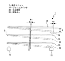
1…電子機器、2…本体、7…操作ユニット、14…エンコーダー、15…プッシュスイッチ、18…回転ギヤ、19…回転ダイヤル、19a…配置孔、19b…配置スペース、19c…配置用凹部、20…外周部、21…内周部、21a…ギヤ部、22…連結部、30…ゴム部材、34…押圧キー、38…揺動キー、39…被操作部、39a…挿入配置孔、39c…被押圧部、7A…操作ユニット、41…圧縮コイルバネ、42…圧縮コイルバネ
DESCRIPTION OF
Claims (13)
前記回転ダイヤルの内側に配置されると共に押圧操作される被押圧部が形成された被操作部を有し前記被押圧部が押圧されて前記基準軸に対して傾斜されて操作される揺動キーと、
前記揺動キーが操作されたときに押圧されて操作信号を出力するプッシュスイッチとを備え、
前記揺動キーは前記被押圧部が押圧操作されたときに前記基準軸を挟んで前記被押圧部の略180°反対側の位置を支点として傾斜されるようにした
操作ユニット。 A rotary dial that is rotated and operated around a predetermined reference axis;
A swing key that is disposed inside the rotary dial and has an operated portion formed with a pressed portion that is pressed, and is operated by being tilted with respect to the reference axis when the pressed portion is pressed. When,
A push switch that is pressed when the swing key is operated and outputs an operation signal;
The operation unit is configured such that when the pressed portion is pressed, the swing key is inclined with a position on the opposite side of the pressed portion approximately 180 ° across the reference shaft as a fulcrum.
前記複数の被押圧部が周方向に離隔して位置された
請求項1に記載の操作ユニット。 A plurality of the pressed parts are provided on the swing key,
The operation unit according to claim 1, wherein the plurality of pressed parts are spaced apart in the circumferential direction.
前記回転ダイヤルの中央部に前記配置用凹部に連通された配置孔が形成され、
前記配置孔に前記プッシュスイッチが配置され、
前記配置用凹部に前記配置孔を覆う状態で前記揺動キーが配置された
請求項1に記載の操作ユニット。 A concave portion for placement is formed on the rotary dial,
An arrangement hole communicated with the arrangement recess is formed in the center of the rotary dial,
The push switch is arranged in the arrangement hole,
The operation unit according to claim 1, wherein the rocking key is arranged in a state of covering the arrangement hole in the arrangement recess.
前記回転ダイヤルに前記基準軸を中心とした周方向に延びるギヤ部が形成され、
前記配置スペースにエンコーダーの少なくとも一部が配置され、
前記エンコーダーに前記ギヤ部と噛合された回転ギヤが設けられた
請求項1に記載の操作ユニット。 An arrangement space extending in the circumferential direction around the reference axis is formed inside the rotary dial,
A gear portion extending in the circumferential direction around the reference axis is formed on the rotary dial,
At least part of the encoder is arranged in the arrangement space;
The operation unit according to claim 1, wherein the encoder is provided with a rotation gear meshed with the gear portion.
前記内周部に前記ギヤ部が形成され、
前記外周部と前記内周部の間に前記配置スペースが形成された
請求項4に記載の操作ユニット。 An outer peripheral portion, an inner peripheral portion located on the inner side of the outer peripheral portion and spaced apart from the outer peripheral portion, a connecting portion that connects one end portion of the outer peripheral portion and one end portion of the inner peripheral portion to the rotary dial; Is provided,
The gear portion is formed on the inner peripheral portion,
The operation unit according to claim 4, wherein the arrangement space is formed between the outer peripheral portion and the inner peripheral portion.
前記挿入配置孔に、押圧されて操作される押圧キーが配置され、
前記押圧キーが操作されたときに押圧されて操作信号を出力するプッシュスイッチが配置された
請求項1に記載の操作ユニット。 An insertion arrangement hole is formed at the center of the swing key,
A pressing key that is operated by being pressed is arranged in the insertion arrangement hole,
The operation unit according to claim 1, wherein a push switch that is pressed to output an operation signal when the pressing key is operated is disposed.
押圧操作が解除されたときに前記揺動キーを前記操作位置から前記非操作位置に戻す弾性変形可能な弾性部材を設け、
前記弾性部材として前記基準軸の軸方向を向くシート状のゴム部材を用いた
請求項1に記載の操作ユニット。 The swing key is moved between a non-operation position before being pressed and an operation position for pressing the push switch,
An elastically deformable elastic member is provided for returning the swing key from the operation position to the non-operation position when the pressing operation is released,
The operation unit according to claim 1, wherein a sheet-like rubber member facing the axial direction of the reference shaft is used as the elastic member.
押圧操作が解除されたときに前記押圧キーを前記押圧位置から前記初期位置に戻す弾性変形可能な弾性部材を設け、
前記弾性部材として前記基準軸の軸方向を向くシート状のゴム部材を用いた
請求項6に記載の操作ユニット。 The pressing key is moved between an initial position before being pressed and a pressing position for pressing the push switch,
An elastically deformable elastic member that returns the pressing key from the pressing position to the initial position when the pressing operation is released;
The operation unit according to claim 6, wherein a sheet-like rubber member facing the axial direction of the reference shaft is used as the elastic member.
前記挿入配置孔に、押圧されて操作される押圧キーが配置され、
前記押圧キーが操作されたときに押圧されて操作信号を出力するプッシュスイッチが配置され、
前記押圧キーは押圧操作される前の初期位置と前記プッシュスイッチを押圧する押圧位置との間で移動され、
押圧操作が解除されたときに前記押圧キーを前記操作位置から前記非操作位置に戻す弾性変形可能な弾性部材として前記ゴム部材を用いた
請求項7に記載の操作ユニット。 An insertion arrangement hole is formed at the center of the swing key,
A pressing key that is operated by being pressed is arranged in the insertion arrangement hole,
A push switch that is pressed when the pressing key is operated and outputs an operation signal is disposed,
The pressing key is moved between an initial position before being pressed and a pressing position for pressing the push switch,
The operation unit according to claim 7, wherein the rubber member is used as an elastically deformable elastic member that returns the pressing key from the operation position to the non-operation position when the pressing operation is released.
押圧操作が解除されたときに前記揺動キーを前記操作位置から前記非操作位置に戻す弾性変形可能な弾性部材を設け、
前記弾性部材として前記基準軸の軸方向において伸縮される圧縮コイルバネを用いた
請求項1に記載の操作ユニット。 The swing key is moved between a non-operation position before being pressed and an operation position when being pressed,
An elastically deformable elastic member is provided for returning the swing key from the operation position to the non-operation position when the pressing operation is released,
The operation unit according to claim 1, wherein a compression coil spring that is expanded and contracted in an axial direction of the reference shaft is used as the elastic member.
押圧操作が解除されたときに前記押圧キーを前記押圧位置から前記初期位置に戻す弾性変形可能な弾性部材を設け、
前記弾性部材として前記基準軸の軸方向において伸縮される圧縮コイルバネを用いた
請求項6に記載の操作ユニット。 The pressing key is moved between an initial position before being pressed and a pressing position for pressing the push switch,
An elastically deformable elastic member that returns the pressing key from the pressing position to the initial position when the pressing operation is released;
The operation unit according to claim 6, wherein a compression coil spring that is expanded and contracted in an axial direction of the reference shaft is used as the elastic member.
前記挿入配置孔に、押圧されて操作される押圧キーが配置され、
前記押圧キーが操作されたときに押圧されて操作信号を出力するプッシュスイッチが配置され、
前記押圧キーは押圧操作される前の初期位置と前記プッシュスイッチを押圧する押圧位置との間で移動され、
押圧操作が解除されたときに前記押圧キーを前記押圧位置から前記初期位置に戻す弾性変形可能な弾性部材を設け、
前記弾性部材として前記基準軸の軸方向において伸縮される圧縮コイルバネを用い、
前記揺動キーを前記操作位置から前記非操作位置に戻す前記圧縮コイルバネと前記押圧キーを前記押圧位置から前記初期位置に戻す圧縮コイルバネとを同軸上に配置した
請求項10に記載の操作ユニット。 An insertion arrangement hole is formed at the center of the swing key,
A pressing key that is operated by being pressed is arranged in the insertion arrangement hole,
A push switch that is pressed when the pressing key is operated and outputs an operation signal is disposed,
The pressing key is moved between an initial position before being pressed and a pressing position for pressing the push switch,
An elastically deformable elastic member that returns the pressing key from the pressing position to the initial position when the pressing operation is released;
Using a compression coil spring that is expanded and contracted in the axial direction of the reference axis as the elastic member,
The operation unit according to claim 10, wherein the compression coil spring that returns the swing key from the operation position to the non-operation position and a compression coil spring that returns the pressing key from the pressing position to the initial position are arranged coaxially.
前記操作ユニットが、
所定の基準軸を中心として回転されて操作される回転ダイヤルと、
前記回転ダイヤルの内側に配置されると共に押圧操作される被押圧部が形成された被操作部を有し前記被押圧部が押圧されて前記基準軸に対して傾斜されて操作される揺動キーと、
前記揺動キーが操作されたときに押圧されて操作信号を出力するプッシュスイッチとを備え、
前記揺動キーは前記被押圧部が押圧操作されたときに前記基準軸を挟んで前記被押圧部の略180°反対側の位置を支点として傾斜されるようにした
電子機器。 An operation unit and a main body operated in response to an operation on the operation unit;
The operating unit is
A rotary dial that is rotated and operated around a predetermined reference axis;
A swing key that is disposed inside the rotary dial and has an operated portion formed with a pressed portion that is pressed, and is operated by being tilted with respect to the reference axis when the pressed portion is pressed. When,
A push switch that is pressed when the swing key is operated and outputs an operation signal;
The electronic device in which the swing key is tilted with a position on the opposite side of the pressed portion approximately 180 ° across the reference axis when the pressed portion is pressed.
Priority Applications (4)
| Application Number | Priority Date | Filing Date | Title |
|---|---|---|---|
| JP2011114202A JP2012243652A (en) | 2011-05-20 | 2011-05-20 | Operation unit and electronic apparatus |
| US13/459,918 US8957331B2 (en) | 2011-05-20 | 2012-04-30 | Operation unit and electronic apparatus |
| TW101116520A TW201308389A (en) | 2011-05-20 | 2012-05-09 | Operation unit and electronic apparatus |
| CN2012101508055A CN102789919A (en) | 2011-05-20 | 2012-05-15 | Operation unit and electronic apparatus |
Applications Claiming Priority (1)
| Application Number | Priority Date | Filing Date | Title |
|---|---|---|---|
| JP2011114202A JP2012243652A (en) | 2011-05-20 | 2011-05-20 | Operation unit and electronic apparatus |
Publications (1)
| Publication Number | Publication Date |
|---|---|
| JP2012243652A true JP2012243652A (en) | 2012-12-10 |
Family
ID=47155297
Family Applications (1)
| Application Number | Title | Priority Date | Filing Date |
|---|---|---|---|
| JP2011114202A Pending JP2012243652A (en) | 2011-05-20 | 2011-05-20 | Operation unit and electronic apparatus |
Country Status (4)
| Country | Link |
|---|---|
| US (1) | US8957331B2 (en) |
| JP (1) | JP2012243652A (en) |
| CN (1) | CN102789919A (en) |
| TW (1) | TW201308389A (en) |
Cited By (2)
| Publication number | Priority date | Publication date | Assignee | Title |
|---|---|---|---|---|
| JP2021124667A (en) * | 2020-02-07 | 2021-08-30 | キヤノン株式会社 | Information input device and imaging unit thereof |
| JP2021124668A (en) * | 2020-02-07 | 2021-08-30 | キヤノン株式会社 | Information input device and imaging unit thereof |
Families Citing this family (6)
| Publication number | Priority date | Publication date | Assignee | Title |
|---|---|---|---|---|
| JP6217073B2 (en) * | 2012-11-22 | 2017-10-25 | オムロン株式会社 | Operation unit |
| BR112015012204B1 (en) * | 2012-11-28 | 2021-07-13 | Honda Motor Co., Ltd | SWITCH |
| USD739361S1 (en) * | 2014-03-28 | 2015-09-22 | eMoMo Technology Co. | Controller for smart furniture (UF) |
| JP7315682B2 (en) * | 2019-08-30 | 2023-07-26 | アルプスアルパイン株式会社 | Operating device |
| KR20210036743A (en) * | 2019-09-26 | 2021-04-05 | 현대자동차주식회사 | Input apparatus for vehicle |
| CN112216546B (en) * | 2020-10-30 | 2024-03-22 | 上海延锋金桥汽车饰件系统有限公司 | Electronic switch |
Citations (5)
| Publication number | Priority date | Publication date | Assignee | Title |
|---|---|---|---|---|
| JPH06178371A (en) * | 1992-12-11 | 1994-06-24 | Matsushita Electric Ind Co Ltd | Jog encoder |
| JPH0877694A (en) * | 1994-09-05 | 1996-03-22 | Yamaha Corp | Operating chip unit |
| JP2005317376A (en) * | 2004-04-28 | 2005-11-10 | Calsonic Kansei Corp | Complex operation input device |
| JP2005317337A (en) * | 2004-04-28 | 2005-11-10 | Teikoku Tsushin Kogyo Co Ltd | Multidirectional press type switch |
| US20080011590A1 (en) * | 2006-07-11 | 2008-01-17 | Montalvo Juan J | Knob force transfer module |
Family Cites Families (11)
| Publication number | Priority date | Publication date | Assignee | Title |
|---|---|---|---|---|
| JP4620894B2 (en) * | 2001-04-06 | 2011-01-26 | キヤノン株式会社 | Electronics |
| JP4338364B2 (en) * | 2002-07-02 | 2009-10-07 | ソニー株式会社 | Portable information communication terminal, program, and recording medium recording the program |
| KR100599285B1 (en) * | 2004-06-15 | 2006-07-14 | 현대자동차주식회사 | Multi-functional steering wheel remote control switch |
| JP4046107B2 (en) | 2004-06-29 | 2008-02-13 | 松下電器産業株式会社 | Multi-directional operation switch |
| US7310084B2 (en) | 2004-06-29 | 2007-12-18 | Matsushita Electric Industrial Co., Ltd. | Multi-way operation switch, input device and input unit |
| JP4061626B2 (en) * | 2004-07-16 | 2008-03-19 | Smk株式会社 | Rotation input device |
| JP5086776B2 (en) | 2007-11-07 | 2012-11-28 | 株式会社テーケィアール | Compound switch |
| JP2009170196A (en) | 2008-01-15 | 2009-07-30 | Panasonic Corp | Multidirectional operation switch |
| CN201340819Y (en) * | 2009-01-16 | 2009-11-04 | 华晶科技股份有限公司 | Polydirectional key structure |
| JP5617389B2 (en) * | 2009-09-30 | 2014-11-05 | パナソニック株式会社 | Multi-directional operation switch |
| TWI423291B (en) * | 2010-09-03 | 2014-01-11 | Primax Electronics Ltd | Rotary switch with push button |
-
2011
- 2011-05-20 JP JP2011114202A patent/JP2012243652A/en active Pending
-
2012
- 2012-04-30 US US13/459,918 patent/US8957331B2/en not_active Expired - Fee Related
- 2012-05-09 TW TW101116520A patent/TW201308389A/en unknown
- 2012-05-15 CN CN2012101508055A patent/CN102789919A/en active Pending
Patent Citations (5)
| Publication number | Priority date | Publication date | Assignee | Title |
|---|---|---|---|---|
| JPH06178371A (en) * | 1992-12-11 | 1994-06-24 | Matsushita Electric Ind Co Ltd | Jog encoder |
| JPH0877694A (en) * | 1994-09-05 | 1996-03-22 | Yamaha Corp | Operating chip unit |
| JP2005317376A (en) * | 2004-04-28 | 2005-11-10 | Calsonic Kansei Corp | Complex operation input device |
| JP2005317337A (en) * | 2004-04-28 | 2005-11-10 | Teikoku Tsushin Kogyo Co Ltd | Multidirectional press type switch |
| US20080011590A1 (en) * | 2006-07-11 | 2008-01-17 | Montalvo Juan J | Knob force transfer module |
Cited By (4)
| Publication number | Priority date | Publication date | Assignee | Title |
|---|---|---|---|---|
| JP2021124667A (en) * | 2020-02-07 | 2021-08-30 | キヤノン株式会社 | Information input device and imaging unit thereof |
| JP2021124668A (en) * | 2020-02-07 | 2021-08-30 | キヤノン株式会社 | Information input device and imaging unit thereof |
| JP7422465B2 (en) | 2020-02-07 | 2024-01-26 | キヤノン株式会社 | Information input device and its imaging device |
| JP7446841B2 (en) | 2020-02-07 | 2024-03-11 | キヤノン株式会社 | Information input device and its imaging device |
Also Published As
| Publication number | Publication date |
|---|---|
| TW201308389A (en) | 2013-02-16 |
| US20120292161A1 (en) | 2012-11-22 |
| US8957331B2 (en) | 2015-02-17 |
| CN102789919A (en) | 2012-11-21 |
Similar Documents
| Publication | Publication Date | Title |
|---|---|---|
| JP2012243652A (en) | Operation unit and electronic apparatus | |
| KR102606499B1 (en) | Electroni device | |
| US8989428B2 (en) | Acoustic systems in electronic devices | |
| JP4843721B2 (en) | Television apparatus, electronic device, and swing support mechanism | |
| US7385150B1 (en) | Sliding mechanism for device with two keyboards | |
| JP2013091334A (en) | Connection device | |
| US20140347803A1 (en) | Broadcast receiving device and electronic device | |
| KR102603448B1 (en) | Key module and mobile terminal having the same | |
| US10593489B2 (en) | Pressing switch mechanism and wearable camera | |
| JP2010136017A (en) | Mobile terminal apparatus | |
| CN103000435B (en) | Key asembly, rotation input device and electronic installation | |
| JP5828724B2 (en) | Multi-directional input device | |
| JP2007142779A (en) | Speaker apparatus | |
| JP2011199766A (en) | Portable terminal device | |
| JP4606886B2 (en) | Electronics | |
| JP2007174588A (en) | Headphone | |
| JP2013065067A (en) | Multidirectional input device | |
| KR20120130045A (en) | Operation unit and electronic apparatus | |
| JP5212123B2 (en) | Electronic equipment and rotary switch mechanism | |
| EP3940500A1 (en) | Mobile terminal with a rotatable screen | |
| WO2014017026A1 (en) | Electronic apparatus | |
| CN216793521U (en) | Key assembly and terminal equipment | |
| CN111343311A (en) | Shell assembly of electronic equipment and electronic equipment | |
| JP5190008B2 (en) | Information processing device | |
| KR20150107095A (en) | Mobile terminal case |
Legal Events
| Date | Code | Title | Description |
|---|---|---|---|
| A621 | Written request for application examination |
Free format text: JAPANESE INTERMEDIATE CODE: A621 Effective date: 20140325 |
|
| A977 | Report on retrieval |
Free format text: JAPANESE INTERMEDIATE CODE: A971007 Effective date: 20141107 |
|
| A131 | Notification of reasons for refusal |
Free format text: JAPANESE INTERMEDIATE CODE: A131 Effective date: 20141118 |
|
| A02 | Decision of refusal |
Free format text: JAPANESE INTERMEDIATE CODE: A02 Effective date: 20150317 |