JP2012242571A - Attachment structure of attention tag, and attention tag for use in the same - Google Patents
Attachment structure of attention tag, and attention tag for use in the same Download PDFInfo
- Publication number
- JP2012242571A JP2012242571A JP2011112012A JP2011112012A JP2012242571A JP 2012242571 A JP2012242571 A JP 2012242571A JP 2011112012 A JP2011112012 A JP 2011112012A JP 2011112012 A JP2011112012 A JP 2011112012A JP 2012242571 A JP2012242571 A JP 2012242571A
- Authority
- JP
- Japan
- Prior art keywords
- tag
- caution
- sandwiching
- projecting piece
- width
- Prior art date
- Legal status (The legal status is an assumption and is not a legal conclusion. Google has not performed a legal analysis and makes no representation as to the accuracy of the status listed.)
- Withdrawn
Links
- 239000000428 dust Substances 0.000 claims description 38
- 230000002093 peripheral effect Effects 0.000 claims description 9
- 238000006243 chemical reaction Methods 0.000 claims description 5
- XLYOFNOQVPJJNP-UHFFFAOYSA-N water Substances O XLYOFNOQVPJJNP-UHFFFAOYSA-N 0.000 claims description 5
- 101100545272 Caenorhabditis elegans zif-1 gene Proteins 0.000 description 32
- 238000003780 insertion Methods 0.000 description 11
- 230000037431 insertion Effects 0.000 description 11
- 239000000463 material Substances 0.000 description 9
- 238000012360 testing method Methods 0.000 description 9
- 238000009434 installation Methods 0.000 description 8
- 238000000034 method Methods 0.000 description 4
- 229920003002 synthetic resin Polymers 0.000 description 2
- 239000000057 synthetic resin Substances 0.000 description 2
- 239000000853 adhesive Substances 0.000 description 1
- 230000001070 adhesive effect Effects 0.000 description 1
- 230000007423 decrease Effects 0.000 description 1
- 238000010586 diagram Methods 0.000 description 1
- 230000008034 disappearance Effects 0.000 description 1
- 238000011156 evaluation Methods 0.000 description 1
- 230000007257 malfunction Effects 0.000 description 1
- 239000004033 plastic Substances 0.000 description 1
- 238000009428 plumbing Methods 0.000 description 1
- 230000002787 reinforcement Effects 0.000 description 1
- 229920003051 synthetic elastomer Polymers 0.000 description 1
- 239000005061 synthetic rubber Substances 0.000 description 1
- 238000012795 verification Methods 0.000 description 1
Images
Landscapes
- Labeling Devices (AREA)
Abstract
Description
本発明は、注意荷札の取付構造とこれに用いる注意荷札に関し、特にアクチュエータ、バルブ類の配管器材への注意喚起方法として注意荷札を取付ける取付け構造と注意荷札に関する。
BACKGROUND OF THE
配管器材(バルブ、アクチュエータ類)を製造するメーカは、製品を出荷する際に、ユーザが正しく、かつ安全に製品を使用することができるようにするため、当該製品の取扱いに関する注意内容を製品に表示している。 Manufacturers of plumbing equipment (valves, actuators, etc.) should be careful about handling the product in order to ensure that the user can use the product correctly and safely when shipping the product. it's shown.
配管器材への当該配管器材の取扱いに関する注意内容の表示には、図8に示すように、注意内容を記述した注意荷札を製品の外部に針金で固着させて表示する方法があり、その他は、注意内容を印刷等したシールを製品の表面に貼着して表示する方法がある。 As shown in Fig. 8, there is a method to display the caution tag describing the caution contents by fixing them to the outside of the product with a wire as shown in Fig. 8. There is a method of sticking and displaying a sticker on which the content of attention is printed on the surface of the product.
配管器材に表示された注意内容がその配管器材を設置し、使用を開始するまでの間の作業内容に関するものである場合には、配管器材の使用が開始された後には当該表示は不要となるが、不要となった表示を取付けたままの状態で配管器材を使用している場合も多く見受けられる。このような状況は、単に当該配管器材の外観が乱雑で見苦しいだけでなく、作業者が勘違いして不要な注意内容に惑わされ、配管器材の故障や作業事故を発生させるおそれもあるため好ましくない。 If the cautions displayed on the piping equipment are related to the work contents between the installation of the piping equipment and the start of use, the indication is not required after the use of the piping equipment is started. However, there are many cases where piping equipment is used with a display that is no longer needed. Such a situation is not preferable because not only the appearance of the piping equipment is messy and unsightly, but the operator may misunderstand the contents of unnecessary precautions and may cause failure of the piping equipment or a work accident. .
このように、不要となった注意内容が表示されたまま配管器材を使用する状況が発生する原因は、注意荷札による表示の場合には、荷札が針金により製品の一部に強固に取付けられているため、取り外すのに意外と手数がかかって面倒なためであり、シールによる表示の場合には、シールの粘着力が強すぎ、シールを配管器材の表面から剥がすことが困難なためである。 In this way, the cause of the situation where the piping equipment is used while the caution contents that are no longer needed are displayed is because the label is firmly attached to a part of the product by the wire in the case of the caution label. This is because it takes a lot of time and effort to remove, and in the case of a display with a seal, the adhesive strength of the seal is too strong, and it is difficult to remove the seal from the surface of the piping equipment.
さらに、注意荷札は、荷札用紙、針金、補強部、留め金などの異なった材質の部品で構成されているため、配管器材からの取外した後、材質毎に分別して廃棄処分する必要があり、このことが注意荷札の配管器材からの取外しをさらに面倒な作業にしている。 In addition, the caution tag is composed of parts of different materials such as tag paper, wire, reinforcement, clasp, etc., so it is necessary to separate and dispose of each material after removing from the piping equipment. This makes the removal of the caution tag from the piping equipment even more troublesome.
特に、配管器材がスプリングリターン型アクチュエータの場合には、取り扱いに関する注意内容の表示は、より重要になる。図8に示すスプリングリターン型アクチュエータ1は、ピストンの往復運動のうち、往きはピストンを加圧することにより作動し、戻りは圧縮されたスプリングの反力により作動する。ピストンの運動によりピストン背面側に体積変化が起こるため、このピストン背面側の部屋の空気を排気及び吸気するために吸排気口を設けている。この吸排気口は、雨水やゴミの浸入を防止するため、通常下向きに設けられる。
In particular, when the piping device is a spring return type actuator, it is more important to display the cautions regarding handling. The spring
前記吸排気口には、設置を完了するまでの間に、図8に示すように、スプリングリターン型アクチュエータ1の内部にゴミ等が入ることを防止するための防塵キャップ2が取付けられ、当該アクチュエータを使用する前には防塵キャップ2を取外す必要がある旨が記述された注意荷札3が針金4によりタイロッド5等に結び付けられ、注意内容を表示している。
As shown in FIG. 8, a
前記吸排気口は、製品の下面側など分かりにくい箇所に設けられていることがあるため、例え製品に注意荷札が表示されていても、その表示箇所が吸排気口から離れていると、防塵キャップ2を取外すことを忘れてしまう場合がある。防塵キャップ2を取外さずにスプリングリターン型アクチュエータ1を使用すると、本来の性能が発揮されずに作動不良となる場合があり、また、毛細管現象により、防塵キャップ2と吸排気口の隙間を通って水が内部に侵入し、内部を腐食させる可能性もある。
The air intake / exhaust port may be provided in a difficult-to-understand location such as the bottom side of the product, so even if a caution label is displayed on the product, if the display location is far from the air intake / exhaust port, You may forget to remove the
したがって、スプリングリターン型アクチュエータの防塵キャップの除去のように、忘れることなく確実に実施することが求められる作業については、その作業の実施についての注意喚起を、作業者が見落とすことがない様に表示する必要がある。また、当該作業の終了後に、もはや不要となった注意喚起の表示が残されたままの状態で配管器材が使用されることがないように、簡単に除去できる方法で表示することが望まれる。 Therefore, for work that is required to be carried out without fail, such as removing the dust-proof cap of the spring return actuator, a warning about the execution of the work is displayed so that the operator will not overlook it. There is a need to. In addition, it is desirable to display by a method that can be easily removed so that the piping equipment is not used in a state where a warning display that is no longer necessary is left after the operation is completed.
ところで、従来から提案されている注意荷札には、例えば、特許文献1や特許文献2などが知られている。
特許文献1には、取付環と吊糸と札本体により構成され、札本体に注意内容を記述し、取付環により対象物の突起部に簡単に取付けることができる下げ札が提案されている。この特許文献1に記載された下げ札は、取付環を防塵キャップの挿入筒部に外嵌し、防塵キャップを吸排気口に取付けることにより、簡単に作業を行うべき部品自体に注意喚起を表示することができる。また、防塵キャップを取外せば、下げ札も一緒に取外すことができる。
Incidentally, for example,
Japanese Patent Application Laid-Open No. H10-228667 proposes a lowering tag that includes an attachment ring, a hanging thread, and a bill body, in which attention content is described in the bill body, and can be easily attached to a protrusion of an object using the attachment ring. The lowering tag described in
また、特許文献2には、取付紐を係止孔に挿通させるだけで簡単に取り付けることができ、被表示体の配置方向に左右されることなく、表示された注意内容が正しい向き及び配置となるべく被表示対に取り付けることができるため、表示を見落したり、見誤ったりするおそれが少ない表示札が提案されている。この特許文献2に記載された表示札は、表示プレートと、この表示プレートを被表示体に取付けるための取付紐が軟質合成樹脂又はゴム等によって一体に成形されており、被表示体に取付ける際には、取付紐を係止孔に挿通させるだけで簡単に取り付けることができる。
Further, in
しかしながら、この特許文献1に記載された下げ札は、取付環、吊糸、札本体により構成されているので、配管部材の使用を開始するまでの間しか使用しない割にはコストアップになり、また、異なった材質の部品で構成されているため、取外し後、材質毎に分別して廃棄処分する必要があるという煩雑さは解消されないという問題がある。
However, since the lowering tag described in
また、特許文献2に記載されている表示札は、取り外す際には、係止孔に挿通されている取付紐を引き抜くか、取付紐を切断する必要があるため、取り外しが面倒であるという問題があるとともに、取り外し後、材質毎に分別して廃棄処分するという問題が依然として存在する。
In addition, when the display tag described in
本発明は、上記の課題点を解決するために開発したものであり、その目的とするところは、被取付体に注意荷札を取り付ける際に、各種の嵌着径に対応可能であり、簡単に取付けることができ、被取付体から注意荷札を取り外す場合にも簡単、かつ、取り外し忘れることなく確実に取外すことができ、安価で、十分な取付強度があり、かつ、取り外し後の廃棄処分が簡単であるとともに、不要時に蓋体を取外すと同時に注意荷札も取外すことができる注意荷札を提供することにある。 The present invention has been developed in order to solve the above-described problems, and the object of the present invention is to support various fitting diameters when attaching a caution tag to a body to be attached. It can be installed, and it is easy to remove the caution tag from the mounted body, and it can be removed securely without forgetting to remove it. It is inexpensive, has sufficient mounting strength, and is easy to dispose of after being removed. Another object of the present invention is to provide a caution tag that can remove a caution tag at the same time that the lid is removed when not needed.
上記目的を達成するため、請求項1に係る発明は、注意荷札用のシート本体の外周よりシート状の挟持突出片を突出形成し、この挟持突出片の先端側の幅を小さく、基端側に向かって大きく形成するとともに、被取付体の嵌着部とこれを被蓋する蓋体との間に前記挟持突出片を介在させ、かつ、前記挟持突出片の適宜の幅を有する位置に挟持させるようにした注意荷札の取付構造である。
In order to achieve the above object, the invention according to
請求項2に係る発明は、前記被取付体は、配管器材であり、この配管器材に設けた前記嵌着部である雌ねじ口とこれを被蓋する前記蓋体である防塵キャップとの間に前記シート本体の挟持突出片を挟持させ、この挟持突出片の挟持位置は、前記配管器材の配管径に応じて前記挟持突出片の適宜の幅を有する位置を挟持させた注意荷札の取付構造である。 According to a second aspect of the present invention, the attached body is a piping device member, and the female screw port that is the fitting portion provided in the piping device member and a dustproof cap that is the lid member that covers the female screw port. The sandwiching projecting piece of the seat body is sandwiched, and the sandwiching projecting position of the sandwiching projecting piece is a mounting structure of a caution tag that sandwiches a position having an appropriate width of the sandwiching projecting piece according to the pipe diameter of the piping device. is there.
請求項3に係る発明は、前記配管器材は、スプリングリターン型アクチュエータであり、このアクチュエータは、ピストンロッドの往復運動を回転運動に変換する回転変換機構の一側にシリンダ機構と、他側にスプリング機構を設けた構造を有し、このアクチュエータに設けた吸排気口の雌ねじ口とこれを一時的に被蓋する防塵キャップとの間に前記挟持突出片を挟持させ、前記吸排気口の口径に対応して前記挟持突出片の適宜の幅を有する位置に挟持させるとともに、前記防塵キャップの取り外しと同時に前記シート本体も取り外し可能とした注意荷札の取付構造である。 According to a third aspect of the present invention, the piping device is a spring return type actuator, and the actuator includes a cylinder mechanism on one side of the rotation conversion mechanism that converts the reciprocating motion of the piston rod into a rotational motion, and a spring on the other side. The mechanism has a structure, and the holding projecting piece is clamped between the female screw port of the intake / exhaust port provided in the actuator and the dust-proof cap that temporarily covers this, so that the diameter of the intake / exhaust port is set. Correspondingly, this is a caution tag mounting structure in which the clamping projecting piece is clamped at a position having an appropriate width, and the seat body can be removed simultaneously with the removal of the dustproof cap.
請求項4に係る発明は、前記挟持突出片を防塵キャップで前記雌ねじ口に挟持したときの当該挟持突出片の幅は、前記雌ねじ口の雌ねじ内周長に対して、10〜25%である注意荷札の取付構造である。 In the invention according to claim 4, the width of the sandwiching projecting piece when the sandwiching projecting piece is sandwiched between the female screw port by a dustproof cap is 10 to 25% with respect to the inner peripheral length of the female screw port. It is a mounting structure of a caution tag.
請求項5に係る発明は、耐水性と柔軟性を有し、かつ、適宜の注意内容を記述した紙状のシート本体を構成し、このシート本体の外周の一部より挟持突出片を一体に突出形成し、この挟持突出片の先端側の幅を小さく、基端側に向かって大きな幅を有するように形成したことを特徴とする注意荷札である。
The invention according to
請求項6に係る発明は、前記挟持突出片の両側の幅は、先端から基端側に沿って当該挟持突出片の両側を順次拡げるようなテーパ形状又は台形状である注意荷札である。
The invention according to
請求項1に係る発明によると、被取付体の嵌着部の嵌着径が異なっても、注意荷札の挟持突出片の幅を各種の嵌着径に対応可能に形成しているので、注意荷札を必要な期間中に確実に装着することが可能であり、不要時に蓋体を取り外すと同時に注意荷札も取り外すことができるため、取り忘れのおそれがなく、その実用価値は極めて大きい。 According to the first aspect of the invention, even if the fitting diameter of the fitting portion of the mounted body is different, the width of the protruding protruding piece of the caution tag is formed so as to be compatible with various fitting diameters. The tag can be securely attached during the necessary period, and the caution tag can be removed at the same time as removing the lid when not needed, so there is no fear of forgetting it and its practical value is extremely high.
請求項2に係る発明によると、バルブやアクチュエータ類の配管器材の雌ねじ口にシート本体の挟持突出片を防塵キャップで挟持できるので、各種の配管径に応じて注意荷札を防塵キャップ自体に直接取り付けることができるため、配管器材の注意荷札としてより効果的な注意喚起が可能となる。 According to the second aspect of the present invention, the clamping projection piece of the seat body can be clamped by the dust cap on the female screw port of the piping equipment of valves and actuators, so the caution tag is directly attached to the dust cap itself according to various pipe diameters. Therefore, it is possible to call attention more effectively as a caution tag for piping equipment.
請求項3に係る発明によると、スプリングリターン型アクチュエータの吸排気口がアクチュエータの下部に設けられていても、防塵キャップと同時に注意荷札を取り外すことができ、防塵キャップの取り外しを忘れるおそれがなく、アクチュエータを工場出荷から設置までの間、作業者への注意喚起を行い、アクチュエータの設置作業で、防塵キャップと同時に注意荷札を取り外すことが可能となる。 According to the invention according to claim 3, even if the intake / exhaust port of the spring return type actuator is provided in the lower part of the actuator, the caution tag can be removed simultaneously with the dustproof cap, and there is no fear of forgetting to remove the dustproof cap, The operator is alerted from factory shipment to installation, and it is possible to remove the caution tag as well as the dustproof cap during the actuator installation work.
請求項4に係る発明によると、注意荷札は、雌ねじ口のねじ山で確実に保持され、しなやかさを保ち、かつ十分な保持時力を発揮することができる。 According to the fourth aspect of the present invention, the caution tag is securely held by the thread of the female screw mouth, can maintain flexibility, and can exhibit sufficient holding force.
請求項5に係る発明によると、耐水性としなやかさを保ち、各種の雌ねじ口等に確実に挟持され、必要な期間中に脱落するおそれがなく、確実に保持され、しかも、構成が簡単であるから、安価に量産に供することができる。
According to the invention of
請求項6に係る発明によると、各種の取付口径に応じて確実に注意荷札を取り付けることが可能となり、もって、その実用的価値は大きい。 According to the sixth aspect of the present invention, it is possible to securely attach the caution tag according to various mounting diameters, and its practical value is great.
以下に、本発明における注意荷札の取付構造とこれに用いる注意荷札の一実施形態を図面に基づいて詳細に説明する。
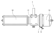
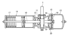
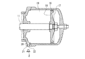
図1は本発明における注意荷札をスプリングリターン型アクチュエータに防塵キャップを用いて取付けた状態を示す正面図であり、図2は図1のスプリングリターン型アクチュエータの断面図であり、図3は図1のスプリング型アクチュエータのシリンダ機構の拡大断面図であり、図4は注意荷札の平面図である。
Hereinafter, an embodiment of a caution tag mounting structure and a caution tag used in the present invention will be described in detail with reference to the drawings.
FIG. 1 is a front view showing a state in which a caution tag in the present invention is attached to a spring return type actuator using a dustproof cap, FIG. 2 is a cross-sectional view of the spring return type actuator of FIG. 1, and FIG. FIG. 4 is an enlarged cross-sectional view of a cylinder mechanism of the spring type actuator, and FIG. 4 is a plan view of a caution tag.
図4に示すように、本発明における注意荷札6は、注意内容を記述する部位であるシート本体7と、注意荷札6を被取付体1の嵌着部9に取付ける部位である挟持突出片8とから構成され、挟持突出片8はシート本体7の外周より一体に突出形成されている。注意荷札6の材質としては、耐水性と柔軟性を有する紙状のシートが望ましく、例えば、プラスチック製の紙が適している。この注意荷札6の厚さは、従来技術に示した札と同等である。
As shown in FIG. 4, the
注意荷札6は、被取付体1の嵌着部である嵌着孔9とこれを被蓋する蓋体2との間で挟持突出片8を挟持させることにより、被取付体1の嵌着部9に取付けられる取付構造を有している。
Caution The
被取付体1の嵌着部である嵌着孔9には種々のサイズが存在するため、注意荷札6の挟持突出片8は、各種の嵌着孔9の嵌着径に対応可能である必要がある。このため、挟持突出片8は、先端側の幅を小さく、基端側に向かって大きな幅を有するように形成されている。これにより、挟持突出片8の適宜の幅を有する部分で、挟持突出片8を被取付体1の嵌着孔9に取付けることができる。
Since there are various sizes of the
注意荷札6を取付ける被取付体1には、アクチュエータ、バルブ等の配管器材がある。配管部材は、工場出荷から器材設置までの間、内部にゴミ等が入らないよう、開口部に蓋体である防塵キャップ2を取付けている。この防塵キャップ2は、配管器材の設置が完了した後、必ず取外されるべき部材であるが、場合によっては取外されないこともある。
防塵キャップ2について取外しの注意喚起を行うため、配管部材に注意荷札を取付ける場合、本発明における注意荷札6を用いると、配管部材の嵌着部9である開口部と当該開口部を被蓋する防塵キャップ2とにより、注意荷札6の挟持突出片8を挟持するだけで簡単に注意荷札6を取付けることができるとともに、防塵キャップ2を取り外すだけで、確実に注意荷札6を取り外すことが可能となる。さらに、取外す必要がある防塵キャップ2自体に、直接その防塵キャップに関する注意内容を記述した注意荷札6を取付けることができるため、効果的に注意喚起を行うことができる。
Caution The
In order to alert the removal of the
本発明における注意荷札6を被取付体であるスプリングリターン型アクチュエータ1に取り付けて使用する例について説明する
An example in which the
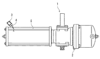
図1に示すスプリングリターン型アクチュエータ1は、図2に断面図に示すように、空気圧により作動するピストンロッド10の往復運動を回転運動に変換する回転変換機構11を内蔵したケース12の一側にシリンダ機構13、他側にスプリング機構14を設けた構造を有している。ピストンロッド10の往復運動のうち、往きはピストン15の前面側16を空気で加圧することにより作動し、戻りは圧縮されたスプリング17の反力により作動する。ピストン15の往復運動によりピストン15の背面側18に体積変化が起こるため、ピストン背面側の部屋19の空気を排気及び吸気する吸排気口20が設けられている。
A spring
図3に示すように、吸排気口20には、他の配管器材を取付ける場合があるため、それらを螺着するための雌ねじ部21が形成されており、スプリングリターン型アクチュエータ1の外表面には雌ねじ口22が開口している。この雌ねじ口22には、スプリング型アクチュエータ1の設置が終了するまでの間、シリンダ室19内にゴミ等が入らないようにするため、防塵キャップ2が嵌め込こまれて閉塞される。
As shown in FIG. 3, since other piping equipment may be attached to the intake /
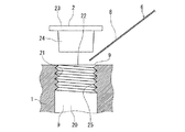
この防塵キャップ2は合成樹脂製であり、図5に示すように、上部に形成された鍔部23と、その下部に先端に向かって若干テーパして細くなる挿入部24を有している。挿入部24の鍔部23直近の直径は雌ねじ部21の内径より若干大きいため、防塵キャップ2の挿入部24を雌ねじ口22に挿入し、鍔部23の下面がスプリングリターン型アクチュエータ1の外表面の当たるまで押し込むと、雌ねじ部21のねじ山25の頂部が挿入部24の外表面に食い込んで防塵キャップ2を係止するとともに、雌ねじ口22は防塵キャップ2の鍔部23で覆われ、雌ねじ口22は確実に閉塞される。
As shown in FIG. 5, the
この雌ねじ口22に注意荷札6を取付けるにあたっては、図5に示すように、注意荷札6の挟持突出片8の適宜の幅の部分まで、嵌着孔9である吸排気口20に形成された雌ねじ口22に差し入れて保持し、その後、通常の作業と同様に蓋体である防塵キャップ2の挿入部24を雌ねじ口22に挿入し、鍔部23の下面がスプリングリターン型アクチュエータ1の外表面の当たるまで押し込むだけでよい。
In attaching the
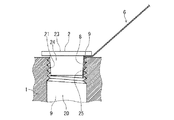
防塵キャップ2で雌ねじ口22を被蓋して注意荷札6の挟持突出片8を挟み込むと、図6に示すように、挟持突出片8は防塵キャップ2の挿入部24と雌ねじ口22の内部に形成されている雌ねじ部21のねじ山25の頂部とにより挟持され、嵌着部9である雌ねじ口22に確実に取付けられる。
When the
挟持突出片8の幅が雌ねじ部21のねじ内周長に対して大きくなると、防塵キャップ2とねじ山25の頂部とが引っ掛かる部分が少なくなる。このため、防塵キャップ2を係止する力が低下し、防塵キャップ2の脱落を招く。また、嵌着孔9である吸排気口20に挟持突出片8を防塵キャップ2の挿入部24により嵌め込むため、挟持突出片8は雌ねじ部21内周に沿って筒状に丸められるので、挟持突出片8と一体に形成されているシート本体7も湾曲し、注意荷札6はしなやかさを失う。注意荷札6は、ある程度のしなやかさを持って被取付体1に取付けられた方が、外力に対して柔軟であり、脱落しにくい。そこで、注意荷札6がしなやかさを有し、吸排気口20に確実に保持される保持力を発揮するためには、嵌着部9における挟持突出片8の幅が雌ねじ部21のねじ内周長に対し、10〜25%程度(後述の実施例参照)であることが望ましい。
When the width of the
挟持突出片8は、先端側の幅を小さく、基端側に向かって大きな幅を有するように形成されているので、被取付体1の嵌着孔9の嵌着径が異なっても、挟持突出片8の先端から基端までの間で、幅がねじ内周長に対し10〜25%となる部分を用い、嵌着部9である雌ねじ口22に取り付けることができる。このため、注意荷札6は十分な取付け強度としなやかさを保った状態で嵌着部9に保持され、取り付けている間に千切れて脱落することがない。
The
スプリングリターン型アクチュエータ1の取付け作業が完了した後、使用開始に先立って防塵キャップ2を取り外せば、防塵キャップ2の挿入部24と雌ねじ部21のねじ山25の頂部とにより挟持突出片8を挟持していた保持力が消失する結果、防塵キャップ2を取り外すと同時に注意荷札6もスプリングリターン型アクチュエータ1の取付け部である吸排気口20から取り外すことができる。
If the
注意荷札6は、シート本体7と挟持突出片8を同じ材質で一体に形成しているので、注意荷札6を取り外した後に分別する必要がなく、そのまま廃棄処分することができる。
Since the
以上のとおり、本発明における注意荷札6によれば、防塵キャップ2で雌ねじ口20を被蓋する際に、注意荷札6の挟持突出片8を適宜な幅の部分まで雌ねじ口20に差し入れ、防塵キャップ2を取付けるだけで、簡単に注意荷札6をスプリングリターン型アクチュエータ1取り付けることができる。しかも、防塵キャップ2に関する作業の注意事項を記述した注意荷札6をその作業対象である防塵キャップ2に直接取付けることができるので、作業者に対し効果的に注意喚起を行うことができる。
As described above, according to the
また、スプリングリターン型アクチュエータ1の取付け完了後に作業者がその防塵キャップ2を取外すと同時に、そこに取付けられていた注意荷札6も確実に取外すことができるため、不要となった注意荷札6を取り忘れるおそれもないので、作業性に優れており、その実用的価値は大きい。
In addition, since the operator can remove the
さらには、注意荷札6は、シート本体7と挟持突出片8を一体に同じ材質で形成しているので、スプリングリターン型アクチュエータ1から取り外した後に注意荷札6を分別する必要はなく、そのまま廃棄処分することができるので、取扱いが極めて容易である。
Further, since the
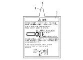
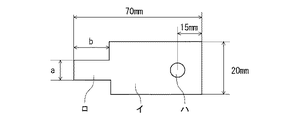
以下に、配管器材の雌ねじ口に防塵キャップを使用して注意荷札を取り付ける場合の、挟持突出片の引張強度と雌ねじ内周長との最適比率検証を実施した例を説明する。図7は、注意荷札6に対応した試験片イの説明図である。
Below, the example which implemented the optimal ratio verification of the tensile strength of a clamping protrusion piece and the internal peripheral length of a female screw in the case of attaching a caution tag using a dustproof cap to the female screw port of piping equipment is explained. FIG. 7 is an explanatory diagram of the test piece A corresponding to the
本試験では、図7において、注意荷札の挟持突出片ロの横幅aの寸法が、雌ねじ内周長に対しどの位の比率であれば十分な保持力を維持することができるのかを検証した。評価においては、試験片が20Nの引張加重まで保持されれば、保持力ありと判定した。なお、図中ハは穴である。 In this test, it was verified in FIG. 7 that the ratio of the dimension of the lateral width a of the sandwiching protruding piece B of the caution tag can be maintained at a sufficient holding force with respect to the inner peripheral length of the female screw. In the evaluation, if the test piece was held up to a tensile load of 20 N, it was determined that there was a holding force. In the figure, C is a hole.
試験片イを取付ける雌ねじ口を模擬するため、呼び径1/8、1/4、1/2の雌ねじを使用した。この雌ねじに対し、挟持突出片ロの横幅aを3mm、10mm、20mmの3通りに形成した試験片イを雌ねじの各呼び径に対応したサイズの防塵キャップにより取付け、試験片イの穴ハに引張加重を徐々に負荷し、試験片が引き抜けたり、防塵キャップが外れたりの何らかの変化が生じた時の引張荷重の値を記録した。 In order to simulate the female screw port for attaching the test piece A, female screws having nominal diameters of 1/8, 1/4, and 1/2 were used. To this female screw, the test piece A with three widths a, 3 mm, 10 mm, and 20 mm of the clamping projecting piece B is attached with a dustproof cap having a size corresponding to each nominal diameter of the female screw, and is attached to the hole C of the test piece A. The tensile load was gradually applied, and the value of the tensile load when the test piece pulled out or the dust cap was removed was recorded.

試験結果は表1に示すとおりであり、aの寸法が、雌ねじの内周長に対して10〜70%の範囲にあれば、十分な保持力が発揮されることを確認できた。 The test results are as shown in Table 1. It was confirmed that if the dimension a is in the range of 10 to 70% with respect to the inner peripheral length of the female screw, a sufficient holding force is exhibited.
一方、前述したように、aの寸法が大き過ぎると、注意荷札1が全体として湾曲し、取付けた状態でのしなやかさが失われる。しなやかさが失われず、かつ、十分な保持力を発揮するためには、aの寸法が雌ねじ内周長の10〜25%の範囲にある必要がある。
On the other hand, as described above, if the dimension a is too large, the
aの寸法を雌ねじ内周長の20%とした場合、各呼び径に対応するaの寸法は、表2に示すとおりである。 When the dimension of a is 20% of the inner peripheral length of the female screw, the dimension of a corresponding to each nominal diameter is as shown in Table 2.
本発明における注意荷札の取付構造によると、配管器材に防塵キャップを取り付ける場合に、使用開始に先立って取外す必要がある防塵キャップに、当該防塵キャップに関する注意内容が記述された注意荷札を簡単に取り付け、保持させることができるとともに、使用開始に先立ち、その防塵キャップを取り外すと同時に、注意荷札も確実に取り外すことができるので、利用価値は極めて大きい。この場合、注意に札の幅は、先端が細くなるテーパまたは曲線が好ましい。 According to the mounting structure of the caution tag in the present invention, when attaching the dust proof cap to the piping equipment, the caution tag describing the cautions regarding the dust proof cap is simply attached to the dust proof cap that needs to be removed before the start of use. Since the dust cap can be removed prior to the start of use, and the caution tag can be reliably removed, the utility value is extremely high. In this case, the width of the bill is preferably a taper or a curve with a thin tip.
1 被取付体(スプリングリターン型アクチュエータ)
2 蓋体(防塵キャップ)
6 注意荷札
7 表示シート体
8 挟持突出片
9 嵌着部(嵌着孔)
21 雌ねじ部
22 雌ねじ口
1 Mounted object (spring return type actuator)
2 Lid (dust cap)
6
21
Claims (6)
Priority Applications (1)
| Application Number | Priority Date | Filing Date | Title |
|---|---|---|---|
| JP2011112012A JP2012242571A (en) | 2011-05-19 | 2011-05-19 | Attachment structure of attention tag, and attention tag for use in the same |
Applications Claiming Priority (1)
| Application Number | Priority Date | Filing Date | Title |
|---|---|---|---|
| JP2011112012A JP2012242571A (en) | 2011-05-19 | 2011-05-19 | Attachment structure of attention tag, and attention tag for use in the same |
Publications (1)
| Publication Number | Publication Date |
|---|---|
| JP2012242571A true JP2012242571A (en) | 2012-12-10 |
Family
ID=47464355
Family Applications (1)
| Application Number | Title | Priority Date | Filing Date |
|---|---|---|---|
| JP2011112012A Withdrawn JP2012242571A (en) | 2011-05-19 | 2011-05-19 | Attachment structure of attention tag, and attention tag for use in the same |
Country Status (1)
| Country | Link |
|---|---|
| JP (1) | JP2012242571A (en) |
-
2011
- 2011-05-19 JP JP2011112012A patent/JP2012242571A/en not_active Withdrawn
Similar Documents
| Publication | Publication Date | Title |
|---|---|---|
| JP4818269B2 (en) | Sealed body with outlet for displaying tampering | |
| JP2009543627A5 (en) | ||
| CA2980724C (en) | Indicator for manual inflator | |
| JP2012242571A (en) | Attachment structure of attention tag, and attention tag for use in the same | |
| CA2474365A1 (en) | Sheet metal cable hook | |
| BRPI0818480A8 (en) | VEHICLE MOUNTED ELECTRONIC APPLIANCE | |
| CA2511987A1 (en) | Tamper indicator lid for container | |
| CN106314398A (en) | Motor vehicle safety device capable of preventing mistaken stepping of accelerator and use method of device | |
| EP4548814A3 (en) | Encasements and methods of manufacture | |
| JP5142876B2 (en) | Article mounting structure | |
| US6012686A (en) | Plastic liner securing device | |
| US20120255331A1 (en) | Ring Security Device | |
| JP4845037B2 (en) | Container stopper | |
| CN202110946U (en) | An air-conditioning compressor capacitor fixing device | |
| JPS5942488Y2 (en) | Holding device for cylindrical objects | |
| CN203637707U (en) | Holding tool | |
| CN204223062U (en) | Tool box opening structure and tool box | |
| JP5557877B2 (en) | Elastic sheet piece with string retainer for string ball | |
| JP2011102447A (en) | Helmet wearing indicator | |
| CN222388692U (en) | An anti-push inner sleeve | |
| CN223878586U (en) | Anti-pull-out combined bottle cap | |
| AU9750401A (en) | A device adapted to be fixed to a wall blindly | |
| KR100829709B1 (en) | Noise reduction device of door trim buzzer prevention boss | |
| CN202031963U (en) | Antitheft sleeve for nuts | |
| CN210395443U (en) | Safety warning assembly and inspection well cover |
Legal Events
| Date | Code | Title | Description |
|---|---|---|---|
| A300 | Withdrawal of application because of no request for examination |
Free format text: JAPANESE INTERMEDIATE CODE: A300 Effective date: 20140805 |