JP2012229068A - Paper reversing device - Google Patents
Paper reversing device Download PDFInfo
- Publication number
- JP2012229068A JP2012229068A JP2011096983A JP2011096983A JP2012229068A JP 2012229068 A JP2012229068 A JP 2012229068A JP 2011096983 A JP2011096983 A JP 2011096983A JP 2011096983 A JP2011096983 A JP 2011096983A JP 2012229068 A JP2012229068 A JP 2012229068A
- Authority
- JP
- Japan
- Prior art keywords
- paper
- reversing
- printing paper
- unit
- printing
- Prior art date
- Legal status (The legal status is an assumption and is not a legal conclusion. Google has not performed a legal analysis and makes no representation as to the accuracy of the status listed.)
- Withdrawn
Links
Images

Landscapes
- Delivering By Means Of Belts And Rollers (AREA)
- Separation, Sorting, Adjustment, Or Bending Of Sheets To Be Conveyed (AREA)
Abstract
【課題】簡易な装置構成で、印刷された印刷用紙を素早く適切に反転させる。
【解決手段】印刷用紙Wを出入りさせるための出入口401cが設けられ、出入口401cから搬入された印刷用紙Wの表裏を反転して出入口401cへ誘導する反転部401と、出入口401c近傍に設けられ、印刷用紙Wを反転部401へ搬入し、反転部401により反転された印刷用紙Wを反転部401から搬出する搬送手段402,403,404と、を備え、反転部401は、出入口401cが下方に向くように垂直方向に対して傾斜して設けられ、搬送手段により搬入された印刷用紙Wを反転部401内へ誘導する搬入ガイド401aと、出入口401cが下方に向くように略垂直方向に設けられ、搬送手段により印刷用紙Wを反転部401外へ搬出させるように誘導する搬出ガイド401bとを備える。
【選択図】図2An object of the present invention is to quickly and appropriately reverse printed printing paper with a simple device configuration.
An inlet / outlet 401c for entering / exiting the printing paper W is provided, a reversing unit 401 for inverting the front and back of the printing paper W carried from the inlet / outlet 401c and guiding it to the inlet / outlet 401c, and the vicinity of the inlet / outlet 401c, Conveying means 402, 403, and 404 for carrying the printing paper W into the reversing unit 401 and carrying out the printing paper W reversed by the reversing unit 401 from the reversing unit 401. It is provided so as to be inclined with respect to the vertical direction, and is provided in a substantially vertical direction so that the carry-in guide 401a for guiding the printing paper W carried by the conveying means into the reversing unit 401 and the inlet / outlet 401c face downward. And a carry-out guide 401b for guiding the printing paper W to be carried out of the reversing unit 401 by the conveying means.
[Selection] Figure 2
Description
本発明は、画像形成装置により画像形成された用紙を反転させて後処理装置へ供給する用紙反転装置に関する。 The present invention relates to a sheet reversing device that inverts a sheet on which an image is formed by an image forming apparatus and supplies the sheet to a post-processing apparatus.
一般的に、印刷用紙の一方の面に印刷する片面印刷と、用紙反転経路を含む循環搬送路を有し、印刷用紙の一方の面に印刷すると共に、この一方の面に印刷された印刷用紙を、用紙反転経路にて表裏反転し、他方の面に印刷を行う両面印刷とが実行可能な画像形成装置(印刷装置)が知られている。 In general, one-sided printing that prints on one side of printing paper, and a circulation conveyance path that includes a paper reversing path, prints on one side of the printing paper, and is printed on this one side. There is known an image forming apparatus (printing apparatus) capable of performing double-sided printing in which a sheet is reversed on the other side through a sheet reversing path and printing is performed on the other side.
このような印刷装置の下流側に設けられ、印刷装置により印刷されて排出される印刷用紙に対して、ステープル処理やパンチング処理、又は裁断処理等の後処理を行う後処理装置が組み合わされて使用される場合がある。 Used in combination with a post-processing device that is provided on the downstream side of such a printing device and performs post-processing such as stapling, punching, or cutting on printing paper that is printed and discharged by the printing device May be.
後処理の実行が指示されている印刷ジョブには、片面印刷、両面印刷が混在しているものも存在するため、前述した後処理装置による後処理の実行が必要な場合、印刷装置は、印刷がなされ、当該印刷装置から排出される印刷用紙の順番を揃えるために、すべての印刷用紙を用紙反転経路上を通過させなければならず、その分、生産性(単位時間あたりの処理数)が低下してしまうという課題があった。 Some print jobs for which post-processing execution is instructed include both single-sided printing and double-sided printing. If the post-processing by the post-processing device described above is required, the printing device In order to arrange the order of the printing papers discharged from the printing apparatus, all the printing papers must pass through the paper reversing path, and productivity (the number of processes per unit time) is correspondingly increased. There was a problem that it would decrease.
また、印刷装置から印刷用紙を排出する方式には、直前に印刷された面が上向きで排出されるフェイスアップ排紙と、下向きで排出されるフェイスダウン排紙が存在する。後処理装置がフェイスアップ排紙方式で排紙経路に接続されており、後処理が指示されているジョブが片面印刷である場合、最先に印刷された印刷用紙を先頭ページとして、順次印刷された印刷用紙を重ねるためには、用紙反転経路にて表裏反転し、後処理装置へ供給する必要がある。この場合でも印刷用紙を用紙反転経路および循環搬送路上を搬送させる必要があり、その分、生産性が低下するという課題があった。 In addition, there are two types of methods for discharging printing paper from the printing apparatus: face-up paper discharge in which the surface printed immediately before is discharged upward, and face-down paper discharge in a downward direction. When the post-processing device is connected to the paper discharge path using the face-up paper discharge method, and the job for which post-processing is instructed is single-sided printing, printing is performed sequentially with the first printed paper as the first page. In order to stack the printed sheets, it is necessary to reverse the front and back through the sheet reversing path and to supply it to the post-processing apparatus. Even in this case, it is necessary to transport the printing paper on the paper reversing path and the circulation transport path, and there is a problem that productivity is reduced correspondingly.
特許文献1及び特許文献2には、水平方向又は下方向へスイッチバック搬送することにより表裏を反転する反転搬送部と、反転搬送部からの用紙の搬出工程において、ステッピングモータの駆動力でローラを回転することにより印刷用紙を搬送する歯付きベルトを備えた用紙反転装置が提案されている。
In
しかしながら、特許文献1及び特許文献2に記載の技術では、水平方向又は下方向へスイッチバック搬送することにより表裏を反転するので、搬出させるためにステッピングモータ等の駆動装置が必要となるので、装置構成が複雑になっていた。
However, in the techniques described in
本発明は、上記課題に鑑みてなされたものであり、簡易な装置構成で、印刷された用紙を素早く適切に反転させる用紙反転装置を提供することを目的とする。 The present invention has been made in view of the above problems, and an object of the present invention is to provide a paper reversing device that quickly and appropriately reverses printed paper with a simple device configuration.
上記目的を達成するため、本発明に係る用紙反転装置の第1の特徴は、印刷用紙を出入りさせるための出入口が下方を向くように設けられ、前記出入口から搬入された印刷用紙の表裏を反転して前記出入口へ誘導する反転手段と、前記出入口近傍に設けられ、印刷用紙を前記反転手段へ搬入し、前記反転手段により反転された印刷用紙を前記反転手段から搬出する搬送手段とを備えたことにある。 In order to achieve the above object, the first feature of the paper reversing device according to the present invention is that the entrance for entering and exiting the printing paper is provided so as to face downward, and the front and back sides of the printing paper carried in from the entrance are reversed. And reversing means for guiding to the entrance / exit, and conveying means provided in the vicinity of the entrance / exit for carrying the printing paper into the reversing means and carrying out the printing paper reversed by the reversing means from the reversing means. There is.
本発明に係る用紙反転装置の第2の特徴は、前記反転手段は、前記出入口が下方に向くように垂直方向に対して傾斜して設けられ、前記搬送手段により搬入された印刷用紙を当該反転手段内へ誘導する搬入ガイドと、前記出入口が下方に向くように略垂直方向に設けられ、前記搬送手段により印刷用紙を当該反転手段外へ搬出させるように誘導する搬出ガイドとを備えたことにある。 A second feature of the paper reversing device according to the present invention is that the reversing means is provided to be inclined with respect to the vertical direction so that the doorway faces downward, and the printing paper carried by the conveying means is reversed. A carry-in guide for guiding into the means, and a carry-out guide which is provided in a substantially vertical direction so that the inlet / outlet faces downward and guides the printing paper out of the reversing means by the conveying means. is there.
本発明に係る用紙反転装置の第3の特徴は、前記搬送手段により搬入された印刷用紙の先端が突き当てられる位置に配置された用紙停止手段とをさらに備えたことにある。 A third feature of the paper reversing device according to the present invention is that it further comprises a paper stopping means arranged at a position where the leading edge of the printing paper carried by the conveying means is abutted.
本発明に係る用紙反転装置の第4の特徴は、前記搬送手段により搬入された印刷用紙を検出する用紙検出手段と、前記反転手段に対する前記用紙停止手段の位置を移動する位置移動手段と、前記用紙検出手段により検出された検出結果に基づいて、前記反転手段に対する前記用紙停止手段の位置が移動するように前記位置移動手段を制御する制御手段と、を更に備えたことにある。 A fourth feature of the paper reversing device according to the present invention is a paper detecting means for detecting a printing paper carried by the conveying means, a position moving means for moving a position of the paper stopping means with respect to the reversing means, And a control means for controlling the position moving means so that the position of the paper stopping means relative to the reversing means is moved based on the detection result detected by the paper detecting means.
本発明に係る用紙反転装置の第5の特徴は、搬送手段は、前記出入口近傍に設けられた回転駆動する駆動ローラと、前記出入口近傍に前記駆動ローラに圧接して設けられ、前記駆動ローラの回転駆動に伴って従動することにより、印刷用紙を前記反転手段へ搬入する第1の従動ローラと、前記出入口近傍に前記駆動ローラに圧接して設けられ、前記駆動ローラの回転駆動に伴って従動することにより、前記反転手段から印刷用紙を搬出する第2の従動ローラと、を有することにある。 A fifth feature of the paper reversing device according to the present invention is that the conveying means is provided in the vicinity of the entrance / exit and is driven to rotate, in the vicinity of the entrance / exit and is provided in pressure contact with the drive roller. A first driven roller that carries printing paper into the reversing means by being driven in accordance with the rotational drive, and is provided in pressure contact with the drive roller in the vicinity of the entrance / exit, and is driven in accordance with the rotational drive of the drive roller. Thus, a second driven roller for carrying out the printing paper from the reversing means is provided.
本発明に係る用紙反転装置の第1の特徴によれば、印刷用紙を出入りさせるための出入口が下方を向くように設けられ、前記出入口から搬入された印刷用紙の表裏を反転して前記出入口へ誘導する反転手段を有するので、簡易な装置構成で、印刷された印刷用紙を素早く適切に反転させることができる。また、出入口が下方を向くように設けられているため、印刷用紙自身の自重を利用して自由落下させることができ、簡易な装置構成にて印刷用紙を反転させることができる。 According to the first feature of the paper reversing device according to the present invention, the entrance for entering and exiting the printing paper is provided so as to face downward, and the front and back of the printing paper carried from the entrance is reversed to the entrance. Since the inversion means for guiding is provided, the printed printing paper can be quickly and appropriately inverted with a simple apparatus configuration. Further, since the doorway is provided so as to face downward, it can be freely dropped by utilizing its own weight, and the printing paper can be reversed with a simple apparatus configuration.
本発明に係る用紙反転装置の第2の特徴によれば、反転手段は、出入口が下方に向くように垂直方向に対して傾斜して設けられ、搬送手段により搬入された印刷用紙を反転手段内へ誘導する搬入ガイドと、出入口が下方に向くように略垂直方向に設けられ、搬送手段により印刷用紙を反転手段外へ搬出させるように誘導する搬出ガイドとを備えているので、搬出ガイドに沿って印刷用紙を自由落下させることにより、出入口から搬送手段により搬出させることができる。また、搬入ガイドと搬出ガイドがある程度の角度を持って設置されることにより、反転手段から搬出される印刷用紙の搬出完了を待たずとも次の印刷用紙を反転手段へ搬入できることとなるため、生産性を向上させることができる。 According to the second feature of the paper reversing device according to the present invention, the reversing means is provided with an inclination with respect to the vertical direction so that the inlet / outlet is directed downward, and the printing paper carried by the conveying means is placed in the reversing means. And a carry-out guide that is provided in a substantially vertical direction so that the inlet / outlet is directed downward and guides the printing paper to be carried out of the reversing means by the conveying means. By allowing the printing paper to fall freely, it can be carried out by the conveying means from the entrance. Also, since the carry-in guide and the carry-out guide are installed at a certain angle, the next printing paper can be carried into the reversing means without waiting for the completion of carrying out of the printing paper carried out from the reversing means. Can be improved.
本発明に係る用紙反転装置の第3の特徴によれば、搬送手段により搬入された印刷用紙の先端が突き当てられる位置に配置された用紙停止手段を更に備えるので、搬入された印刷用紙の斜行補正を行うことができる。 According to the third feature of the paper inverting device according to the present invention, the paper inverting device further includes paper stopping means arranged at a position where the leading edge of the printing paper carried in by the conveying means is abutted. Line correction can be performed.
本発明に係る用紙反転装置の第4の特徴によれば、反転手段に対する用紙停止手段の位置が移動するように位置移動手段を制御するので、印刷用紙の搬入される速度に応じて用紙停止手段の位置が変更することができる。 According to the fourth feature of the paper reversing device according to the present invention, the position moving means is controlled so that the position of the paper stopping means relative to the reversing means is moved, so that the paper stopping means according to the speed at which the printing paper is carried in The position of can be changed.
本発明に係る用紙反転装置の第5の特徴によれば、出入口近傍に設けられた回転駆動する駆動ローラと、出入口近傍に駆動ローラに圧接して設けられ、駆動ローラの回転駆動に伴って従動することにより、印刷用紙を反転手段へ搬入する第1の従動ローラと、出入口近傍に駆動ローラに圧接して設けられ、駆動ローラの回転駆動に伴って従動することにより、反転手段から印刷用紙を搬出する第2の従動ローラとを有するので、簡易な構成で、反転手段内に印刷用紙が2枚存在することができるようになり、高い生産性を発揮させることが可能となる。 According to the fifth feature of the sheet reversing device according to the present invention, a driving roller that is rotationally driven provided in the vicinity of the entrance / exit and a pressure roller that is provided in pressure contact with the driving roller in the vicinity of the entrance / exit, and is driven as the driving roller rotates. Thus, the first driven roller for bringing the printing paper into the reversing means and the driving roller are provided in pressure contact with the driving roller in the vicinity of the entrance and exit, and the printing paper is removed from the reversing means by being driven as the driving roller rotates. Since the second driven roller to be carried out is provided, two printing sheets can be present in the reversing means with a simple configuration, and high productivity can be exhibited.
本発明の実施の形態について図面を参照して説明する。 Embodiments of the present invention will be described with reference to the drawings.
本発明の一実施形態では、インクジェットヘッドから黒および/またはカラーのインクを吐出して印刷用紙に印刷を行う画像形成装置と、ステープル処理などの後処理を実行する後処理装置と、画像形成装置により印刷された印刷用紙を反転して後処理装置へ供給する用紙反転装置とを備えた画像形成システムを例に挙げて説明する。 In one embodiment of the present invention, an image forming apparatus that discharges black and / or color ink from an inkjet head to perform printing on printing paper, a post-processing apparatus that performs post-processing such as stapling, and the image forming apparatus An image forming system including a paper reversing device that reverses the printing paper printed by the above and supplies it to the post-processing apparatus will be described as an example.
<画像形成システムの構成>
図1は、本発明の一実施形態である画像形成システムの全体構成を示す全体構成図である。
<Configuration of image forming system>
FIG. 1 is an overall configuration diagram showing an overall configuration of an image forming system according to an embodiment of the present invention.
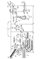
図1に示すように画像形成システム1は、印刷用紙Wに対する印刷を実行する画像形成装置2と、印刷用紙Wに対して後処理を実行する後処理装置3と、画像形成装置2により印刷された印刷用紙を反転して後処理装置3へ供給する用紙反転装置4を備えている。
As shown in FIG. 1, the
画像形成装置2は、サイド給紙部10と、内部給紙部20と、印刷部(画像形成部)30と、排紙部40と、反転部50とを備えている。
The image forming apparatus 2 includes a side
サイド給紙部10は、印刷用紙Wが積載される給紙台11と、この給紙台11から最上位置の印刷用紙Wのみを給紙搬送路SR上へ搬送させる1次給紙部12と、この1次給紙部12によって搬送された印刷用紙Wを循環搬送路CR上へ搬送する2次給紙部14とを備えている。1次給紙部12により給紙搬送路SR上を搬送された印刷用紙Wは2次給紙部14に突き当てられることにより印刷用紙Wの先端の位置あわせと斜行修正が行われ、その後所定のタイミングで印刷部30へ向かって循環搬送路CR上を搬送される。
The side
内部給紙部20は、印刷用紙Wが積載される給紙台21a,21b,21c,21dと、これらの給紙台21a,21b,21c,21dから最上位置の印刷用紙Wのみを給紙搬送路SR上へ搬送させる1次給紙部22a,22b,22c,22dとを備えている。
The internal
1次給紙部22a,22b,22c,22dによりそれぞれ給紙搬送路SR上へ搬送された印刷用紙Wは、給紙搬送路SR上に設置された搬送ローラ23等の複数の搬送ローラにより給紙搬送路SR上を搬送され、2次給紙部14に突き当てられる。これにより、印刷用紙Wに弛みが生じ、この弛みにより印刷用紙Wの先端の位置あわせと斜行修正がなされ、その後、所定のタイミングで印刷部30へ向かって循環搬送路CR上を搬送される。
The printing paper W transported onto the paper feed transport path SR by the primary
このように、2次給紙部14には、サイド給紙部10及び内部給紙部20から印刷用紙Wが搬送され、さらに、後述する反転部50からも印刷用紙Wが搬送される。
In this way, the printing paper W is conveyed from the side
そのため、搬送方向における2次給紙部14の手前には、給紙された印刷用紙Wの搬送経路と、表面印刷後に装置内を循環搬送され反転部50にて反転された裏面印刷の用紙が循環して搬送されてくる経路とが合流する合流地点が存在する。この合流地点を基準に、給紙機構側の経路を給紙搬送路SRと称し、画像形成装置2内を印刷用紙Wが循環される経路を循環搬送路CRと称している。
Therefore, in front of the secondary paper feed unit 14 in the transport direction, the transport path of the fed printing paper W and the paper for back side printing that is circulated through the apparatus after front side printing and reversed by the reversing
印刷部30は、複数の印字ヘッドが組み込まれたヘッドユニット31と、ヘッドユニット31の対向面に設けられた環状の搬送ベルト32とを備えており、2次給紙部14により給紙された印刷用紙Wは、印刷条件により定められる速度で搬送ベルト32上を搬送されながら、ヘッドユニット31から吐出されたインクによりライン単位で印刷用紙Wに印刷される。
The
印刷部30により印刷された印刷用紙Wは、循環搬送路CR上に配置された搬送ローラ等によって筐体内を循環搬送路CR上を搬送される。循環搬送路CR上には、循環搬送路CR上を搬送された印刷用紙Wを排紙部40へ誘導するか、又は循環搬送路CR上を再循環させるかを切り替える切り替え機構43が備えられている。
The printing paper W printed by the
排紙部40は、画像形成装置2の筐体から突出したトレイ形状をした排紙台41と、排紙台41に印刷用紙Wを誘導する一対の排紙ローラ42とを有している。そして、切り替え機構43により排紙部40に誘導された印刷用紙Wは、排紙ローラ42により排紙台41に搬送され、排紙台41に搬送される直前に印刷された印刷面を下にして積載される。
The
反転部50は、印刷用紙Wを反転させる反転台51と、循環搬送路CRから反転台51へ印刷用紙Wを搬送し、又は反転台51から循環搬送路CR上へ印刷用紙Wを搬送する反転ローラ52を備えている。
The reversing
切り替え機構43により反転部50に誘導された印刷用紙Wは、反転ローラ52により循環搬送路CRから反転台51に搬送され、所定時間経過後、反転台51から循環搬送路CRへ搬送されることにより、循環搬送路CRに対して表裏が反転する。そして、表裏が反転された印刷用紙Wは、循環搬送路CR上に設けられた搬送ローラ53等の複数のローラにより循環搬送路CR上を搬送され、2次給紙部14に突き当てられる。これにより、印刷用紙Wに弛みが生じ、この弛みにより印刷用紙Wの先端の位置あわせと斜行修正がなされ、その後、所定のタイミングで印刷部30へ向かって循環搬送路CR上を搬送される。
The printing paper W guided to the reversing
また、循環搬送路CRには、切替機構44が設けられており、印刷用紙Wの後処理を行う場合は、この切替機構44が搬送方向を切替ることにより、印刷用紙Wが用紙反転装置4へ誘導される。すなわち、印刷用紙Wは、片面印刷からの後処理が指定されている場合には、印刷部30により片面が印刷された後に切替機構44により画像形成装置2から排出され、両面印刷からの後処理が指定されている場合には、片面(表面)が印刷された印刷用紙が反転部50にて反転された後に印刷部30により他面(裏面)が印刷された後に切替機構44により画像形成装置2から排出され、反転装置4へ誘導される。
In addition, a
用紙反転装置4は、印刷用紙の表裏を反転する反転部401と、反転部401の出入口に設けられた回転駆動する駆動ローラ402と、反転部401の出入口に駆動ローラ402に圧接して設けられ、入口搬送経路MR1上を搬送された印刷用紙Wを反転部401へ搬送する第1の従動ローラ403と、反転部401の出入口に駆動ローラ402に圧接して設けられ、反転部401から出口搬送経路MR2へ印刷用紙Wを搬送する第2の従動ローラ404とを備えている。なお、これら用紙反転装置4が備える構成については、後述する。
The
後処理装置3は、紙折処理部110を備えており、印刷用紙Wの紙折を行う場合には、切替機構112が搬送方向を切替ることにより、印刷用紙Wが紙折処理部110に導かれる。
The post-processing device 3 includes a paper
後処理経路FR上を紙折処理部110に誘導された印刷用紙Wは、二つ折り、三つ折り、Z折り等の紙折りが行われ、二つ折り又は三つ折りが行われた場合には、紙折トレイ111に排紙される。
The printing paper W guided to the paper
一方、紙折を行わない場合、印刷用紙Wは紙折処理部110に誘導されることなく、後処理経路FR上をパンチ処理部120に供給され、また、紙折処理部110によりZ折りが行われた場合においても、印刷用紙Wは紙折処理部110から後処理経路FR上を搬送されパンチ処理部120に供給される。
On the other hand, when paper folding is not performed, the printing paper W is not guided to the paper
パンチ処理部120では、印刷用紙Wに対し印刷ジョブに応じてパンチ穴を穿孔させるパンチ処理が実行され、後処理経路FR上をトップトレイ101、スタッカトレイ102、又はスタッカトレイ103の方向へ搬送される。
In the
トップトレイ101方向に搬送された印刷用紙Wは、トップトレイ101上に積載され、スタッカトレイ102方向へ搬送された印刷用紙Wは、ステープル処理部130により、長辺綴じ又は短辺綴じの位置に応じてステープル処理が実行された後、スタッカトレイ102上に積載される。スタッカトレイ103方向へ搬送された印刷用紙Wは、中綴じ処理部140により、中綴じ(中折り)処理が実行された後、スタッカトレイ103上に積載される。
The printing paper W transported in the direction of the
図2は、本発明の一実施形態である画像形成システムが備える用紙反転装置4の構成を示す構成図である。
FIG. 2 is a configuration diagram showing the configuration of the
図2に示すように、用紙反転装置4には、画像形成装置2の切替部44を作用させることにより装置外へ排出された印刷用紙Wが供給される。この供給された印刷用紙Wは、搬送ローラ405により入口搬送経路MR1へ搬送される。
As shown in FIG. 2, the
搬送ローラ405は、駆動源となる駆動モータ(図示しない)と機械的に接続され、駆動モータの駆動により回転駆動する駆動ローラ405aと、駆動ローラ405aと圧接することにより、回転する従動ローラ405bとを備えており、駆動ローラ405aと従動ローラ405bとが圧接して回転することにより、印刷用紙Wを入口搬送経路MR1へ搬送する。
The
入口搬送経路MR1は、印刷用紙Wの表裏を反転する反転部401と接続されており、反転部401の出入口401cには、駆動ローラ402と、第1の従動ローラ403が設けられている。
The entrance conveyance path MR1 is connected to a reversing
駆動ローラ402は、駆動源となる駆動モータ(図示しない)と機械的に接続され、駆動モータの駆動によりJ方向に回転駆動する。
The
第1の従動ローラ403は、駆動ローラ402に圧接して設けられ、駆動ローラ402のJ方向への回転駆動に伴って従動することにより、入口搬送経路MR1上を搬送された印刷用紙Wを反転部401へ搬送する。
The first driven
反転部401は、駆動ローラ402と第1の従動ローラ403とにより、搬入された印刷用紙Wを誘導する搬入ガイド401aと、駆動ローラ402と第2の従動ローラ404とにより反転部401から印刷用紙Wを搬出させるように誘導する搬出ガイド401bとを備えている。
The reversing
搬入ガイド401aは、出入口401cが下方に向くように垂直方向に対して約30°傾斜して設けられている。なお、この垂直方向に対する搬入ガイド401aの傾き角度(ここでは、30°)を進入角度という。
The carry-in
また、搬出ガイド401bは、出入口401cが下方に向くように略垂直方向に設けられている。なお、この垂直方向に対する搬出ガイド401bの傾き角度を排出角度(ここでは0°)という。
The carry-
第2の従動ローラ404は、駆動ローラ402に圧接して設けられ、駆動ローラ402のJ方向への回転駆動に伴って従動することにより、搬出ガイド401bにより誘導された印刷用紙Wを出口搬送経路MR2へ搬送する。
The second driven
また、反転部401には、搬入ガイド401aに沿って搬送された印刷用紙Wを突き当てる突き当て板410が設けられている。
The reversing
突き当て板410には、突き当て支持部材411が接続されており、この支持部材411にはラックギア411aが設けられている。
An
ラックギア411aの近傍には、プーリ412が回転可能に支持されており、このプーリの回転軸と同軸に装着された歯車413がラックギア411aに噛合している。
A
プーリ412の近傍には、モータ415が設けられており、モータ415の出力軸に取り付けられたプーリ416と、プーリ412との間を無端のベルト414が掛け渡されている。
A
これにより、モータ415が回転駆動することによりプーリ416,412が回転し、ラックギア411a,歯車413へ駆動力が伝達され、支持部材411が動かされることにより突き当て板410がF1方向又はF2方向に上下移動する。
As a result, when the
また、反転部401の搬入ガイド401aの近傍には、駆動ローラ402と第1の従動ローラ403とにより搬入された印刷用紙Wを検出する用紙センサ421が設けられている。
In addition, a paper sensor 421 that detects the printing paper W carried in by the driving
<画像形成システム1の機能構成>
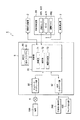
図3は、本発明の一実施形態である画像形成システム1の機能構成を示す機能構成図である。
<Functional Configuration of
FIG. 3 is a functional configuration diagram showing a functional configuration of the
図3に示すように、これらの構成のうち、画像形成装置2と、後処理装置3とについては、上述したので、説明を省略する。 As shown in FIG. 3, among these configurations, the image forming apparatus 2 and the post-processing apparatus 3 have been described above, and a description thereof will be omitted.
画像形成システム1は、ネットワーク9を介して端末100と接続されている。
The
端末100は、ソフトウェアを実行することにより、画像データを生成し、生成した画像データと、両面印刷又は片面印刷の指定や後処理の有無等の設定情報とを印刷ジョブとしてネットワーク9を介して画像形成システム1へ送信する。ここで、後処理の有無とは、例えば、パンチ処理、ステープル処理、又は中綴じ処理を実行するか否かを示す情報である。
The terminal 100 generates image data by executing software, and the generated image data and setting information such as the designation of double-sided printing or single-sided printing and the presence / absence of post-processing as a print job via the network 9 Send to forming
また、画像形成システム1は、画像読み取り部200及びファックス受信部400と接続されている。
The
画像読み取り部200は、画像形成システム1の画像形成装置2の上部に設けられ、図示しないが、原稿を載置するコンタクトガラス、このコンタクトガラスに対して接離自在に設けられたカバー、コンタクトガラス上に載置された原稿を走査する走査ユニット、走査された画像を集束するレンズ、及び集束された画像を処理する画像処理部を備えている。
The
そして、走査ユニットがコンタクトガラス上に載置された原稿を1ライン毎に走査し、画像処理部が走査された画像を処理することにより、画像形成システム1が印刷するための画像データを読み取る。
Then, the scanning unit scans the original placed on the contact glass for each line, and the image processing unit processes the scanned image, whereby the
ファックス受信部400は、ファクシミリ通信可能なデバイスであり、ファクシミリ受信した画像データを画像形成システム1へ供給する。
The
画像形成システム1は、画像形成装置2と、用紙反転装置4と、後処理装置3と、制御装置5とを備えている。
The
制御装置5は、操作部60と、制御部70と、ネットワークインタフェース部80と、外部インタフェース部82とを備えている。
The
操作部60は、画像形成装置2の上部に設けられ、表示/入力パネル61と、読み取りや印刷等を開始させるためのスタートキー、読み取りや印刷等を停止させるためのストップキー、印刷枚数等を入力するためのテンキー(いずれも図示せず)等の各種操作キーとを備え、利用者操作に基づく操作信号を制御部70に供給する。
The
操作部60の表示/入力パネル61は、前面に配置された感圧式あるいは静電式の透明なタッチパネルと、このタッチパネルの裏面に配置された液晶表示パネル(いずれも図示せず)とを有している。利用者は、液晶表示パネルの表示画面を見ながら、タッチパネルの表面を指などで直接触れることで、印刷を開始させるための操作、後処理を実行するか否かを設定する設定操作、及び用紙反転装置4で用紙反転処理を実行するか否かを設定する設定操作等各種の設定入力操作を行うことができる。
The display / input panel 61 of the
ネットワークインタフェース部80は、ネットワークカードなどの通信インタフェースであり、このネットワークインタフェース部80により画像形成システム1をネットワーク9に接続することによって、ネットワーク9に接続された端末100から画像データを受信したり、各種信号を送受信したりする。
The
外部インタフェース部82は、画像読み取り部200との接続インタフェースであり、画像読み取り部200により読み取られた画像データ、及びファックス受信部400からファクシミリ受信した画像データを制御部70へ供給する。
The
制御部70は、画像形成システム1の中枢的な制御を行う。また、制御部70は、その機能上、受信部71と、判定部72と、機器制御部73とを備える。
The
受信部71は、ネットワークインタフェース部80を介して端末100から送信された印刷ジョブを受信する。また、受信部71は、外部インタフェース部82を介して画像読み取り部200から送信された印刷ジョブや、ファックス受信部400からファクシミリ受信した印刷ジョブを受信する。
The receiving
判定部72は、用紙センサ421,422による検出結果に基づいて、印刷用紙Wが反転部401へ搬入されたか否かを判定する。具体的には、判定部72は、用紙センサ422が搬送ローラ405により入口搬送経路MR1へ搬送された印刷用紙Wを検出した後に、用紙センサ421が駆動ローラ402と第1の従動ローラ403とにより搬入された印刷用紙Wを検出したか否かを判定する。
The
機器制御部73は、受信部71により受信した印刷ジョブに基づいて、画像形成装置2、用紙反転装置4、及び後処理装置3を制御する。特に、機器制御部73は、判定部72により印刷用紙Wが反転部401へ搬入されたと判定された場合、反転部401に対する突き当て板410の位置が移動するようにモータ415を制御する。
The
<画像形成システム1の作用>
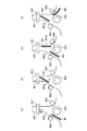
図4(a)〜(d)は、本発明の一実施形態である画像形成システム1の作用を示した図である。
<Operation of
4A to 4D are views showing the operation of the
図4(a)に示すように、入口搬送経路MR1を搬送された印刷用紙W(W1)は、反転部401の出入口に設けられた駆動ローラ402及び第1の従動ローラ403により、搬入ガイド401aに沿って搬送され、印刷用紙W1の後端が駆動ローラ402及び第1の従動ローラ403の圧接点を通過しても、その角度のまま搬入ガイド401aに沿って上昇する。
As shown in FIG. 4A, the printing paper W (W1) transported along the entrance transport path MR1 is brought into the carry-in
そして、図4(b)に示すように、搬入ガイド401aに沿って上昇した印刷用紙W1は、突き当て板410に突き当たる。このように、印刷用紙W1は、突き当て板410に突き当たることにより、弛み、これにより斜行補正される。なお、突き当て板410に突き当たった際、紙質(柔らかさ)によって、弛む量は異なっている。
Then, as shown in FIG. 4B, the printing paper W <b> 1 that has risen along the carry-in
搬入ガイド401aは、出入口401cが下方に向くように垂直方向に対して約30°傾斜して設けられているので、印刷用紙W1は、垂直方向に対して約30°の角度で突き当て板410に突き当てられる。そして、突き当て板410に先端が突き当てられた印刷用紙W1は、後端がG方向に旋回する。
Since the carry-in
そして、G方向に旋回された印刷用紙Wは、図4(c)に示すように、搬出ガイド401bに沿って自由落下し、駆動ローラ402及び第2の従動ローラ404の圧接点に到達する。
Then, as shown in FIG. 4C, the printing paper W swung in the G direction freely falls along the carry-
このとき、次の印刷用紙である印刷用紙W(W2)が、駆動ローラ402及び第1の従動ローラ403により、搬入ガイド401aに沿って搬送されている。
At this time, the printing paper W (W2) which is the next printing paper is conveyed along the carry-in
そして、図4(d)に示すように、駆動ローラ402及び第2の従動ローラ404の圧接点に到達した印刷用紙Wは、駆動ローラ402及び第2の従動ローラ404により、出口搬送経路MR2へ搬送される。
Then, as shown in FIG. 4D, the printing paper W that has reached the pressure contact between the driving
このように、本発明の一実施形態である画像形成システム1が備える用紙反転装置4では、回転駆動する駆動ローラ402と、この駆動ローラ402の回転駆動に伴って従動する第1の従動ローラ403及び第2の従動ローラ404とにより、印刷用紙Wの搬入及び搬出を行うので、簡易な構成で、反転部401内に印刷用紙Wが2枚存在することができ、その分、印刷装置内で用紙を反転させた場合と比べ高い生産性を発揮させることができる。
As described above, in the
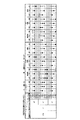
図5は、本発明の一実施形態である画像形成システム1により通紙実験を行った実験結果を示した図である。図5に示した実験では、印刷用紙Wを、“ハガキ”、“普通紙”、“厚紙”、“薄紙”の4種類とし、それぞれ進入角度を“20°”、“30°”、“40°”、突き当て板410の位置を、“5(mm)”、“10(mm)”、“15(mm)”、“20(mm)”、“25(mm)”、搬送速度を、“120(ppm)”、“150(ppm)”、“180(ppm)”としたときの通紙状態を観測した。なお、“普通紙”、“厚紙”、“薄紙”の3種類の印刷用紙については、印刷サイズを“A4サイズ”及び“A3”サイズとして通紙状態を観測した。
FIG. 5 is a diagram showing a result of an experiment in which a paper passing experiment is performed by the
ここで、突き当て板410の位置Lとは、下記の(数式1)で表される長さである。
Here, the position L of the
L=LT−LW ・・・(数式1)
L:突き当て板410の位置
LT:駆動ローラ402及び第2の従動ローラ404の圧接点から突き当て板410の位置までの印刷用紙Wが搬送される経路長
LW:印刷用紙Wの搬送方向の長さ
また、図5に示した図では、50枚通紙実験した結果、全ての印刷用紙が適切に通紙された場合を“○”とし、50枚通紙実験した結果、1枚でも適切に通紙されなかった場合を“×”とし、50枚通紙実験した結果、1枚でも適切に紙ジャム(紙詰まり)が発生した場合を“ジャム”として表記している。
L = LT−LW (Equation 1)
L: position of the
図5に示すように、印刷用紙Wが、“普通紙”、印刷サイズが“A3サイズ”とした場合、進入角度を“20°”では、突き当て板410の位置及び搬送速度にかかわらず、紙ジャムが発生する場合が多いことがわかる。
As shown in FIG. 5, when the printing paper W is “plain paper” and the printing size is “A3 size”, the approach angle is “20 °” regardless of the position of the
一方、印刷用紙Wが、“普通紙”、印刷サイズが“A3サイズ”とした場合でも、進入角度を“30°”以上にすると、紙ジャムの発生率は低下し、適切に通紙できる場合が多くなる。 On the other hand, even when the printing paper W is “plain paper” and the printing size is “A3 size”, if the entrance angle is set to “30 °” or more, the occurrence rate of paper jam is reduced and the paper can be passed appropriately. Will increase.
これは、進入角度が小さいと、先行する印刷用紙Wが突き当て板410に突き当たることによる生じる弛みが大き過ぎ、後続の印刷用紙Wと接触して紙ジャムが発生するためである。
This is because if the approach angle is small, the slack generated by the preceding printing paper W hitting the
また、突き当て板410の位置Lを長くした場合においても、搬送速度が速くなるに従って、適切に搬送されることがわかる。
In addition, even when the position L of the
このように、印刷用紙Wの搬送速度に応じて、適切な突き当て板410の位置Lを設定することにより、印刷用紙Wを適切に搬送することができる。
Thus, the printing paper W can be appropriately conveyed by setting the appropriate position L of the
そこで、制御部70の機器制御部73は、判定部72により印刷用紙Wが反転部401へ搬入されたと判定された場合、反転部401に対する突き当て板410の位置が移動するようにモータ415を制御する。例えば、図5に示す実験結果に基づいて、予め搬送速度に、適切に搬送可能な突き当て板410の位置Lを関連づけた位置算出テーブルとして記憶しておく。そして、機器制御部73は、用紙センサ421,422による検出結果から、搬入される印刷用紙Wの搬送速度を算出し、位置算出テーブルに基づいて、算出された搬送速度から、適切に搬送な可能な突き当て板410の位置Lを抽出する。
Therefore, when the
そして、機器制御部73は、抽出された突き当て板410の位置Lになるように、モータ415を制御させる。
And the
また、図5に示すように、印刷サイズを“A3サイズ”とした場合、印刷用紙Wが、“普通紙”であると、進入角度を“20°”では、紙ジャムが発生する場合が多いのに対し、印刷用紙Wが、“厚紙”、“薄紙”では、進入角度が“20°”であっても、突き当て板410の位置Lが、“10(mm)”であれば、適切に通紙できる。
Further, as shown in FIG. 5, when the print size is “A3 size”, if the print paper W is “plain paper”, paper jam often occurs when the entry angle is “20 °”. On the other hand, if the printing paper W is “thick paper” or “thin paper”, the position L of the
これは、印刷用紙Wが、“普通紙”の場合、先行する印刷用紙Wが突き当て板410に突き当たることにより生じる弛みが大き過ぎ、後続の印刷用紙Wと接触して紙ジャムが発生するが、印刷用紙Wが、“厚紙”の場合、先行する印刷用紙Wが突き当て板410に突き当たることによる生じる弛みが比較的小さく、後続の印刷用紙Wと接触して紙ジャムが発生することがないことによる。
This is because when the printing paper W is “plain paper”, the slack caused by the preceding printing paper W hitting the
また、印刷用紙Wが、“薄紙”の場合、先行する印刷用紙Wが突き当て板410に突き当たることにより生じる弛みは大きいが、後続の印刷用紙Wと接触しても、印刷用紙W自体が柔らかいので、紙ジャムは生じないことによる。
Further, when the printing paper W is “thin paper”, the slack caused by the preceding printing paper W hitting the
このように、進入角度が“30°”以上であれば、印刷用紙Wの種類、搬送速度にかかわらず、適切に突き当て板410の位置を設定することにより、適切に通紙できる。
As described above, when the approach angle is “30 °” or more, regardless of the type of the printing paper W and the conveyance speed, it is possible to appropriately pass the paper by appropriately setting the position of the
また、搬出ガイド401bの排出角度は“0°”であるので、突き当てられた印刷用紙Wは自由落下して、突き当てられた直下に設けられた駆動ローラ402及び第2の従動ローラ404により、出口搬送経路MR2へ搬送される。
Further, since the discharge angle of the carry-
以上のように、本発明の一実施形態である画像形成システム1によれば、回転駆動する駆動ローラ402と、この駆動ローラ402の回転駆動に伴って従動する第1の従動ローラ403及び第2の従動ローラ404と、印刷用紙Wを出入りさせるための出入口401cが設けられ、出入口401cから搬入された印刷用紙Wの表裏を反転して出入口401cへ誘導する反転部401とを備え、反転部401は、出入口401cが下方に向くように垂直方向に対して傾斜して設けられ、駆動ローラ402及び第1の従動ローラ403により搬入された印刷用紙Wを反転部401内へ誘導する搬入ガイド401aと、出入口401cが下方に向くように略垂直方向に設けられ、駆動ローラ402及び第2の従動ローラ404により印刷用紙Wを反転部401外へ搬出させるように誘導する搬出ガイド401bとを有しているので、簡易な装置構成で、印刷された印刷用紙Wを素早く適切に反転させることができる。さらに反転装置を通過した印刷用紙は表裏が反転され、直前に印刷された印刷面を下にして排出されるため、ユーザーから片面印刷の指示がなされている場合、印刷データの印刷される順序を並べ替える必要がなく、受け取った順番で昇順に印刷処理をすればよい。したがって、片面印刷後の後処理が指示されている印刷ジョブについても高い生産性を発揮できることになる。
As described above, according to the
なお、本発明の一実施形態では、画像形成装置2と、用紙反転装置4と、後処理装置3と、制御装置5とを備えた画像形成システム1を例に挙げて説明したが、これに限らず、画像形成装置2と、用紙反転装置4と、後処理装置3とのそれぞれに、制御装置が備えられた構成にしてもよい。
In the embodiment of the present invention, the
また、本発明の一実施形態では、画像形成装置2、用紙反転装置4と、後処理装置3、及び制御装置5を備え、制御装置5が、画像形成装置2、用紙反転装置4、及び後処理装置3を制御する画像形成システム1を例に挙げて説明したが、これに限らず、画像形成装置2、用紙反転装置4、及び後処理装置3をそれぞれを制御する3つの制御装置を備えるようにしてもよい。
In one embodiment of the present invention, the image forming apparatus 2, the
1…画像形成システム
2…画像形成装置
3…後処理装置
4…用紙反転装置
5…制御装置
60…操作部
70…制御部
71…受信部
72…判定部
73…機器制御部
401…反転部
401a…搬入ガイド
401b…搬出ガイド
401c…出入口
402…駆動ローラ
403…第1の従動ローラ
404…第2の従動ローラ
405…搬送ローラ
405a…駆動ローラ
405b…従動ローラ
410…突き当て板
411…支持部材
412…プーリ
413…歯車
414…ベルト
415…モータ
416,412…プーリ
421,422…用紙センサ
DESCRIPTION OF
Claims (5)
前記出入口近傍に設けられ、印刷用紙を前記反転手段へ搬入し、前記反転手段により反転された印刷用紙を前記反転手段から搬出する搬送手段と、
を備えたことを特徴とする用紙反転装置。 Reversing means provided so that the entrance for entering and exiting the printing paper faces downward, and reversing the front and back of the printing paper carried in from the entrance and guiding it to the entrance;
A conveying means provided in the vicinity of the inlet / outlet for carrying the printing paper into the reversing means and carrying out the printing paper reversed by the reversing means from the reversing means;
A sheet reversing device comprising:
前記出入口が下方に向くように垂直方向に対して傾斜して設けられ、前記搬送手段により搬入された印刷用紙を当該反転手段内へ誘導する搬入ガイドと、
前記出入口が下方に向くように略垂直方向に設けられ、前記搬送手段により印刷用紙を当該反転手段外へ搬出させるように誘導する搬出ガイドとを備えた
ことを特徴とする請求項1に記載の用紙反転装置。 The inversion means is
A carry-in guide that is provided to be inclined with respect to the vertical direction so that the doorway is directed downward, and guides the printing paper carried by the carrying unit into the reversing unit;
2. A carry-out guide that is provided in a substantially vertical direction so that the entrance / exit is directed downward, and that guides the print sheet to be carried out of the reversing unit by the transport unit. Paper reversing device.
をさらに備えたことを特徴とする請求項1または2に記載の用紙反転装置。 A paper stopping means arranged at a position where the leading edge of the printing paper carried by the conveying means is abutted;
The sheet reversing device according to claim 1, further comprising:
前記反転手段に対する前記用紙停止手段の位置を移動する位置移動手段と、
前記用紙検出手段により検出された検出結果に基づいて、前記反転手段に対する前記用紙停止手段の位置が移動するように前記位置移動手段を制御する制御手段と、
を更に備えたことを特徴とする請求項3記載の用紙反転装置。 Paper detection means for detecting the printing paper carried in by the transport means;
Position moving means for moving the position of the paper stopping means relative to the reversing means;
Control means for controlling the position moving means so that the position of the paper stopping means relative to the reversing means moves based on the detection result detected by the paper detecting means;
The sheet reversing device according to claim 3, further comprising:
前記出入口近傍に設けられた回転駆動する駆動ローラと、
前記出入口近傍に前記駆動ローラに圧接して設けられ、前記駆動ローラの回転駆動に伴って従動することにより、印刷用紙を前記反転手段へ搬入する第1の従動ローラと、
前記出入口近傍に前記駆動ローラに圧接して設けられ、前記駆動ローラの回転駆動に伴って従動することにより、前記反転手段から印刷用紙を搬出する第2の従動ローラと、
を有することを特徴とする請求項1〜4のいずれか1項記載の用紙反転装置。 The conveying means is
A driving roller that is rotationally driven in the vicinity of the entrance;
A first driven roller that is provided in pressure contact with the drive roller in the vicinity of the entrance and exits the reversing unit by being driven by the rotation of the drive roller;
A second driven roller which is provided in pressure contact with the drive roller in the vicinity of the entrance and exits the printing paper from the reversing means by being driven by the rotational drive of the drive roller;
The sheet reversing device according to claim 1, wherein the sheet reversing device is provided.
Priority Applications (1)
| Application Number | Priority Date | Filing Date | Title |
|---|---|---|---|
| JP2011096983A JP2012229068A (en) | 2011-04-25 | 2011-04-25 | Paper reversing device |
Applications Claiming Priority (1)
| Application Number | Priority Date | Filing Date | Title |
|---|---|---|---|
| JP2011096983A JP2012229068A (en) | 2011-04-25 | 2011-04-25 | Paper reversing device |
Publications (1)
| Publication Number | Publication Date |
|---|---|
| JP2012229068A true JP2012229068A (en) | 2012-11-22 |
Family
ID=47430992
Family Applications (1)
| Application Number | Title | Priority Date | Filing Date |
|---|---|---|---|
| JP2011096983A Withdrawn JP2012229068A (en) | 2011-04-25 | 2011-04-25 | Paper reversing device |
Country Status (1)
| Country | Link |
|---|---|
| JP (1) | JP2012229068A (en) |
-
2011
- 2011-04-25 JP JP2011096983A patent/JP2012229068A/en not_active Withdrawn
Similar Documents
| Publication | Publication Date | Title |
|---|---|---|
| US8931773B2 (en) | Sheet folding device having inclined stacking surface | |
| JP2010047350A (en) | Printing device and paper discharge control method in printing device | |
| US8851468B2 (en) | Sheet stacking apparatus and image forming apparatus | |
| JP5294680B2 (en) | Sheet processing apparatus and image forming apparatus | |
| US20160340143A1 (en) | Sheet processing apparatus equipped with lateral displacement correction function | |
| JP5582449B2 (en) | Image forming apparatus | |
| JP2008308243A (en) | Sheet processing apparatus and stacker provided with the same | |
| JP2013014393A (en) | Image forming device | |
| JP2020015180A (en) | Recording device | |
| CN110539559B (en) | Recording apparatus | |
| JP5273601B2 (en) | Paper post-processing device | |
| JP5628582B2 (en) | Image forming apparatus | |
| JP2020090375A (en) | Sheet stacking device and image forming system | |
| JP2012158012A (en) | Printing apparatus | |
| JP2012229068A (en) | Paper reversing device | |
| JP2019202876A (en) | Recording device | |
| JP2012218351A (en) | Image forming device | |
| JP2018083315A (en) | Printing device | |
| JP5708074B2 (en) | Image forming apparatus, post-processing apparatus, image forming system, and transport unit | |
| US12522006B2 (en) | Sheet post-processing device and image forming system | |
| JP2007055752A (en) | Image forming apparatus | |
| JP5978740B2 (en) | Intermediate transport unit and image forming system having the same | |
| JP2020090374A (en) | Sheet loading device and image formation system | |
| JP2012000880A (en) | Image forming apparatus and image forming system | |
| JP2024104728A (en) | SHEET POST-TREATING DEVICE AND IMAGE FORMING SYSTEM INCLUDING THE SAME |
Legal Events
| Date | Code | Title | Description |
|---|---|---|---|
| A300 | Withdrawal of application because of no request for examination |
Free format text: JAPANESE INTERMEDIATE CODE: A300 Effective date: 20140701 |