JP2012221189A - Arithmetic circuit, arithmetic processing unit, and control method of arithmetic circuit - Google Patents
Arithmetic circuit, arithmetic processing unit, and control method of arithmetic circuit Download PDFInfo
- Publication number
- JP2012221189A JP2012221189A JP2011085882A JP2011085882A JP2012221189A JP 2012221189 A JP2012221189 A JP 2012221189A JP 2011085882 A JP2011085882 A JP 2011085882A JP 2011085882 A JP2011085882 A JP 2011085882A JP 2012221189 A JP2012221189 A JP 2012221189A
- Authority
- JP
- Japan
- Prior art keywords
- exponent
- mantissa
- shift
- exponent part
- value
- Prior art date
- Legal status (The legal status is an assumption and is not a legal conclusion. Google has not performed a legal analysis and makes no representation as to the accuracy of the status listed.)
- Withdrawn
Links
Images











Classifications
-
- G—PHYSICS
- G06—COMPUTING OR CALCULATING; COUNTING
- G06F—ELECTRIC DIGITAL DATA PROCESSING
- G06F7/00—Methods or arrangements for processing data by operating upon the order or content of the data handled
- G06F7/38—Methods or arrangements for performing computations using exclusively denominational number representation, e.g. using binary, ternary, decimal representation
- G06F7/48—Methods or arrangements for performing computations using exclusively denominational number representation, e.g. using binary, ternary, decimal representation using non-contact-making devices, e.g. tube, solid state device; using unspecified devices
- G06F7/483—Computations with numbers represented by a non-linear combination of denominational numbers, e.g. rational numbers, logarithmic number system or floating-point numbers
-
- G—PHYSICS
- G06—COMPUTING OR CALCULATING; COUNTING
- G06F—ELECTRIC DIGITAL DATA PROCESSING
- G06F7/00—Methods or arrangements for processing data by operating upon the order or content of the data handled
- G06F7/38—Methods or arrangements for performing computations using exclusively denominational number representation, e.g. using binary, ternary, decimal representation
- G06F7/48—Methods or arrangements for performing computations using exclusively denominational number representation, e.g. using binary, ternary, decimal representation using non-contact-making devices, e.g. tube, solid state device; using unspecified devices
- G06F7/499—Denomination or exception handling, e.g. rounding or overflow
- G06F7/49942—Significance control
Landscapes
- Engineering & Computer Science (AREA)
- Physics & Mathematics (AREA)
- General Physics & Mathematics (AREA)
- Theoretical Computer Science (AREA)
- Computational Mathematics (AREA)
- Computing Systems (AREA)
- Mathematical Analysis (AREA)
- Mathematical Optimization (AREA)
- Pure & Applied Mathematics (AREA)
- General Engineering & Computer Science (AREA)
- Nonlinear Science (AREA)
- Complex Calculations (AREA)
Abstract
【課題】固定精度の浮動小数点数同士の正確な和を高速に実現する演算方式を提供する。
【解決手段】演算回路は、第1の仮数部と第1の指数部とを含む第1の加減算対象データを格納するレジスタと、第2の仮数部と第2の指数部とを含む第2の加減算対象データを格納するレジスタと、第1の指数部と第2の指数部との差の絶対値が、第1仮数部の先行ゼロ計数値以上であるか否かに応じて第1のシフト量及び第2のシフト量を算出するシフト量生成部と、第1の仮数部を第1のシフト量だけシフトし、第2の仮数部を前記第2のシフト量だけシフトするシフト部と、第1のシフト後仮数部と第2のシフト後仮数部とを加減算した倍精度による倍精度仮数部を出力する加減算部と、倍精度仮数部を正規化した正規化倍精度仮数部の下位側を正規化した下位側正規化仮数部と、正規化指数部から所定の固定精度の桁数だけ減算した下位側正規化指数部を算出する正規化部を有する。
【選択図】図29An arithmetic method for realizing an accurate sum of fixed-precision floating-point numbers at high speed is provided.
An arithmetic circuit includes a register for storing first addition / subtraction target data including a first mantissa part and a first exponent part, a second mantissa part and a second exponent part including a second exponent part. Depending on whether or not the absolute value of the difference between the first exponent part and the second exponent part is greater than or equal to the leading zero count value of the first mantissa part. A shift amount generation unit that calculates the shift amount and the second shift amount, a shift unit that shifts the first mantissa part by the first shift amount, and shifts the second mantissa part by the second shift amount; An addition / subtraction unit for outputting a double precision mantissa part by double precision obtained by adding / subtracting the first post-shift mantissa part and the second post-shift mantissa part, and a subordinate of the normalized double precision mantissa part by normalizing the double precision mantissa part Subtract the number of digits with a specified fixed precision from the lower-order normalized mantissa part and the normalized exponent part. Having a normalization unit for calculating a lower normalization exponent.
[Selection] Figure 29
Description
本願開示は、演算回路、演算処理装置、及び演算回路の制御方法に関する。 The present disclosure relates to an arithmetic circuit, an arithmetic processing device, and an arithmetic circuit control method.
銀行等において勘定処理を行なう勘定系や、一部の科学技術計算などでは、数値表現や演算における誤差を小さくするために、多倍長、または、可変長の数値表現形式が採用されることがある。このような場合、符号と指数とをひとつの整数で表現し、仮数については、ひとつの整数で表現した符号と指数とは別の整数の列で表現することが多い。また、このような数値表現を採用した場合には、整数演算を利用して数値同士の計算が実現されることも多くあった。 In account systems that perform account processing in banks, etc., and in some scientific and technical calculations, in order to reduce errors in numerical expressions and operations, multiple-precision or variable-length numerical expressions may be adopted. is there. In such a case, the sign and the exponent are represented by one integer, and the mantissa is often represented by a string of integers different from the sign and the exponent represented by one integer. In addition, when such a numerical expression is adopted, calculation between numerical values is often realized using integer arithmetic.
それに対し、多倍長や可変長の浮動小数点演算を、固定精度の浮動小数点演算を用いて実現する方法が提案されている。固定精度の浮動小数点演算については、ハードウエアによる処理手段を提供している場合が多いため、そのようなハードウエア処理手段を用いることで、全ての処理をソフトウェアに行なわせる場合よりも処理の高速化をはかることができる。例えば、多倍長の2進浮動小数点演算を、2倍長の浮動小数点演算を用いて行うライブラリも存在する。これらの方法では、固定精度浮動小数点数の組(要素同士の足し算を実行せずに組のまま用いることから「未評価の和」とも呼ばれる)によりひとつの数を表現し、その組同士の算術を適切に実行することで、大きな精度の算術(四則演算)を実現している。 On the other hand, there has been proposed a method for realizing multiple-precision or variable-length floating-point arithmetic using fixed-precision floating-point arithmetic. For fixed-precision floating-point arithmetic, hardware-based processing means are often provided, and using such hardware processing means makes processing faster than if all processing is performed by software. Can be realized. For example, there is a library that performs a double-precision binary floating-point operation using a double-precision floating-point operation. In these methods, a single number is represented by a pair of fixed-precision floating-point numbers (also called “unevaluated sum” because it is used as it is without performing addition between elements), and the arithmetic between the pairs is expressed. By executing appropriately, arithmetic with high precision (four arithmetic operations) is realized.
固定精度の浮動小数点演算においては、演算結果は必ずしも正確にはならない。たとえば、固定精度の浮動小数点数同士の正確な和を実現するためには、計算結果を2つの固定精度の浮動小数点数で表現する必要がある。このような正確な和のアルゴリズムは、次のようになる。 In fixed-precision floating-point operations, the operation results are not always accurate. For example, in order to realize an accurate sum of fixed-precision floating-point numbers, it is necessary to express the calculation result by two fixed-precision floating-point numbers. The exact sum algorithm is as follows.
Two_sum(X, Y)
z = fl(X + Y)
w = fl(z - X)
v = fl(z - w)
z1 = fl(Y - w)
z2 = fl(v - X)
zz = fl(z1 - z2)
return(z, zz)
ここでfl(X+Y)は、X+Yの真の値を、浮動小数点数にマッピングした結果、即ち浮動小数点形式の限られた精度内で表現した結果を示す。上記のTwo_sumによって得られる2数z及びzzは、正確な意味においてz+zz=X+Yを満たす。zはX+Yの最重要部(most significant part)を固定精度浮動小数点の精度内で表現した値であり、zzは固定精度浮動小数点の精度で表現しきれなかった残余分を表す。
Two_sum (X, Y)
z = fl (X + Y)
w = fl (z-X)
v = fl (z-w)
z1 = fl (Y-w)
z2 = fl (v-X)
zz = fl (z1-z2)
return (z, zz)
Here, fl (X + Y) represents the result of mapping the true value of X + Y to a floating-point number, that is, the result expressed within the limited precision of the floating-point format. The two numbers z and zz obtained by the above Two_sum satisfy z + zz = X + Y in an accurate sense. z is a value representing the most significant part of X + Y within the precision of the fixed precision floating point, and zz represents the remainder that cannot be expressed with the precision of the fixed precision floating point.
マッピング時に発生する丸め処理方法として、10進数で代表的な丸め方法である四捨五入を例に取り説明する。簡単のために固定精度浮動小数点数の精度は10進2桁とする。この場合、20000と−1との2数の和は、上記のTwo_sumにより以下のように計算される。 As a rounding method that occurs at the time of mapping, a rounding method that is a representative rounding method using decimal numbers will be described as an example. For simplicity, the precision of fixed-precision floating-point numbers is assumed to be two decimal digits. In this case, the sum of the two numbers 20000 and −1 is calculated as follows using the above Two_sum.
X = 20000
Y = -1
z = fl(X+Y) = 20000
w = fl(z−X) = 0
v = fl(z−w) = 20000
z1 = fl(Y−w) = -1
z2 = fl(v−X) = 0
zz = fl(z1−z2) = -1
この計算により、正確な意味においてz+zz=X+Yであるようなz及びzzを求めることができる。
X = 20000
Y = -1
z = fl (X + Y) = 20000
w = fl (z-X) = 0
v = fl (z-w) = 20000
z1 = fl (Y−w) = − 1
z2 = fl (v−X) = 0
zz = fl (z1-z2) =-1
This calculation makes it possible to obtain z and zz such that z + zz = X + Y in an accurate sense.
上記のアルゴリズムでは、ひとつの和z+zzを実現するために、6回もの浮動小数点演算が必要となる。この正確な和アルゴリズムは、多倍長や可変長の浮動小数点演算を、固定精度の浮動小数点演算を用いて実現する場合に頻繁に用いられるものである。従って、この正確な和アルゴリズムを高速化することが望まれる。 In the above algorithm, as many as six floating point operations are required to realize one sum z + zz. This accurate sum algorithm is frequently used when multiple-precision or variable-length floating-point arithmetic is realized using fixed-precision floating-point arithmetic. Therefore, it is desirable to speed up this accurate sum algorithm.
以上を鑑みると、固定精度の浮動小数点数同士の正確な和を高速に実現する演算方式が望まれる。 In view of the above, there is a demand for an arithmetic method that realizes an accurate sum of fixed-precision floating-point numbers at high speed.
2値を加減算した結果である所定の固定精度の範囲で表される加減算値に対する補正値を算出する演算回路は、N進法(Nは2以上の整数)による第1の固定精度浮動小数点数の第1の仮数部と、前記第1の仮数部に対する指数を表す第1の指数部とを含む第1の形式の第1の加減算対象データを保持する第1の入力レジスタと、前記N進法による第2の固定精度浮動小数点数の第2の仮数部と、前記第2の仮数部に対する指数を表す第2の指数部を含み、前記第2の指数部の値が前記第1の指数部の値より小さい第1の条件と、前記第1の指数部から前記第1の仮数部の最上位ビットから連続する0値を計数した結果である第1の先行ゼロ計数値を減算した第1の減算後指数部から、前記第2の指数部から前記第2の仮数部の最上位ビットから連続する0値を計数した結果である第2の先行ゼロ計数値を減算した第2の減算後指数部を減算した結果が、前記所定の固定精度の桁数より小さい値となる第2の条件とを同時に満たす第1の形式の第2の加減算対象データを保持する第2の入力レジスタと、前記第1の指数部と前記第2の指数部の差の絶対値が、前記第1の先行ゼロ計数値以上である場合には前記第1の先行ゼロ計数値を、前記第1の先行ゼロ計数値よりも小さい場合には前記第1の指数部と前記第2の指数部の差の絶対値を、第1のシフト量として算出する第1のシフト量生成部と、前記第1の指数部と前記第2の指数部の差の絶対値が、前記第1の先行ゼロ計数値以上である場合には前記第1の指数部から前記第2の指数部と前記第1の先行ゼロ計数値を減算した値を、前記第1の先行ゼロ計数値よりも小さい場合にはゼロを、第2のシフト量として算出する第2のシフト量生成部と、前記第1の仮数部を、前記第1のシフト量だけシフトした第1のシフト後仮数部を算出する第1のシフト部と、前記第2の仮数部を、前記第2のシフト量だけシフトした第2のシフト後仮数部を算出する第2のシフト部と、前記第1のシフト後仮数部と前記第2のシフト後仮数部を加減算した前記所定の固定精度の倍精度による倍精度仮数部と、前記第1のシフト後仮数部と前記第2のシフト後仮数部の加減算によるキャリーを出力する加減算部と、前記第1の指数部及び前記第2の指数部のうち小さい方の指数部に、前記第2のシフト量を加減算したシフト後指数部を算出するシフト後指数生成部と、前記シフト後指数部に、前記キャリーを加減算した補正指数部を算出する補正指数生成部と、前記補正指数部を正規化した正規化指数部と、前記倍精度仮数部を正規化した正規化倍精度仮数部とを算出する第1の正規化部と、前記正規化倍精度仮数部の下位側の前記所定の固定精度の桁数分の仮数部を正規化した下位側正規化仮数部と、前記正規化指数部から前記所定の固定精度の桁数だけ減算した下位側正規化指数部を算出する第2の正規化部を有することを特徴とする。 An arithmetic circuit that calculates a correction value for an addition / subtraction value represented by a range of a predetermined fixed precision that is a result of adding / subtracting two values is a first fixed-precision floating-point number in N-ary (N is an integer of 2 or more). A first input register for holding first addition / subtraction data in a first format including a first mantissa part of the first mantissa part and a first exponent part representing an exponent for the first mantissa part; A second mantissa part of a second fixed-precision floating-point number according to the modulo and a second exponent part representing an exponent for the second mantissa part, wherein the value of the second exponent part is the first exponent A first condition smaller than the value of the first part, and a first leading zero count value obtained by subtracting a continuous zero value from the most significant bit of the first mantissa part from the first exponent part. From the exponent part after subtraction of 1, from the second exponent part to the most significant bit of the second mantissa part The result of subtracting the second post-subtraction exponent part obtained by subtracting the second leading zero count value, which is the result of counting consecutive zero values, is a value smaller than the predetermined fixed precision digit number. A second input register that holds second addition / subtraction target data in the first format that simultaneously satisfies the condition, and an absolute value of a difference between the first exponent part and the second exponent part is The first leading zero count value is greater than the leading zero count value if it is greater than or equal to the leading zero count value, and the difference between the first exponent portion and the second exponent portion is less than the first leading zero count value. A first shift amount generation unit that calculates an absolute value as a first shift amount, and an absolute value of a difference between the first exponent part and the second exponent part is greater than or equal to the first leading zero count value The second exponent and the first leading zero count value are subtracted from the first exponent , A second shift amount generation unit that calculates zero as a second shift amount when the first leading zero count value is smaller than the first leading zero count value, and the first mantissa unit, the first shift amount A first shift unit for calculating a first post-shift mantissa shifted by a second shift, and a second post-shift mantissa for calculating a second post-shift mantissa by shifting the second mantissa by the second shift amount. A shift unit, a double precision mantissa unit with double precision of the predetermined fixed precision obtained by adding and subtracting the first post-shift mantissa part and the second post-shift mantissa part, the first post-shift mantissa part and the first mantissa part After the shift in which the second shift amount is added or subtracted to the smaller exponent part of the first exponent part and the second exponent part. A post-shift index generation unit for calculating an exponent part, and the post-shift index A correction exponent generation unit that calculates a correction exponent part obtained by adding and subtracting the carry, a normalized exponent part that normalizes the correction exponent part, and a normalized double precision mantissa part that normalizes the double precision mantissa part, A first normalization part that calculates a lower-order normalized mantissa part obtained by normalizing a mantissa part corresponding to the number of digits of the predetermined fixed precision on the lower side of the normalized double-precision mantissa part, and the normalized exponent A second normalization unit that calculates a lower-order normalized exponent part obtained by subtracting the predetermined number of digits of fixed precision from the part.
2値を加減算した結果である所定の固定精度の範囲で表される加減算値に対する修正値を算出する演算回路と、前記2値を加減算した結果である所定の固定精度の範囲で表される加減算値に対する修正値を算出する修正値演算命令をデコードする命令制御部とを有する演算処理装置において、前記演算回路は、N進法(Nは2以上の整数)による第1の固定精度浮動小数点数の第1の仮数部と、前記第1の仮数部に対する指数を表す1つの第1の指数部を含む第1の形式の第1の加減算対象データを保持する第1の入力レジスタと、前記N進法による第2の固定精度浮動小数点数の第2の仮数部と、前記第2の仮数部に対する指数を表す1つの第2の指数部を含み、前記第2の指数部が前記第1の指数部より小さいことを前提とする第1の条件と、前記第1の指数部から前記第1の仮数部の最上位ビットから連続する0値を計数した結果である第1の先行ゼロ計数値を減算した第1の減算後指数部から、前記第2の指数部から前記第2の仮数部の最上位ビットから連続する0値を計数した結果である第2の先行ゼロ計数値を減算した第2の減算後指数部を減算した結果が、前記所定の固定精度の桁数より小さい値となることを前提とする第2の条件を同時に満たす第1の形式の第2の加減算対象データを保持する第2の入力レジスタと、前記第1の指数部と前記第2の指数部の差の絶対値が、前記第1の先行ゼロ計数値以上である場合には前記第1の先行ゼロ計数値を、前記第1の先行ゼロ計数値よりも小さい場合には前記第1の指数部と前記第2の指数部の差の絶対値を、第1のシフト量として算出する第1のシフト量生成部と、前記第1の指数部と前記第2の指数部の差の絶対値が、前記第1の先行ゼロ計数値以上である場合には前記第1の指数部から前記第2の指数部と前記第1の先行ゼロ計数値を減算した値を、前記第1の先行ゼロ計数値よりも小さい場合にはゼロを、第2のシフト量として算出する第2のシフト量生成部と、前記第1の仮数部を、前記第1のシフト量だけシフトした第1のシフト後仮数部を算出する第1のシフト部と、前記第2の仮数部を、前記第2のシフト量だけシフトした第2のシフト後仮数部を算出する第2のシフト部と、前記第1のシフト後仮数部と前記第2のシフト後仮数部を加減算した前記所定の固定精度の倍精度による倍精度仮数部と、前記加減算によるキャリーを出力する加減算部と、前記第1の指数部及び前記第2の指数部のうち小さい方の指数部に、前記第2のシフト量を加減算したシフト後指数部を算出するシフト後指数生成部と、前記シフト後指数部に、前記キャリーを加減算した補正指数部を算出する補正指数生成部と、前記補正指数部を正規化した正規化指数部と、前記倍精度仮数部を正規化した正規化倍精度仮数部とを算出する第1の正規化部と、前記正規化倍精度仮数部の下位側の前記所定の固定精度による仮数部を正規化した下位側正規化仮数部と、前記正規化指数部から前記所定の固定精度の桁数だけ減算した下位側正規化指数部を算出する第2の正規化部を有することを特徴とする。 An arithmetic circuit for calculating a correction value for an addition / subtraction value represented by a predetermined fixed accuracy range obtained by adding / subtracting two values, and an addition / subtraction represented by a predetermined fixed accuracy range obtained by adding / subtracting the two values And an instruction control unit that decodes a correction value calculation instruction for calculating a correction value for the value. The calculation circuit includes a first fixed-precision floating-point number in N-ary (N is an integer of 2 or more). A first input register holding first addition / subtraction data in a first format including a first mantissa part of the first mantissa part and a first exponent part representing an exponent for the first mantissa part; A second mantissa part of a second fixed-precision floating-point number in base notation and one second exponent part representing an exponent for the second mantissa part, wherein the second exponent part is the first exponent part The first article on the assumption that it is smaller than the exponent From the first post-subtraction exponent part obtained by subtracting a first leading zero count value that is a result of counting consecutive 0 values from the most significant bit of the first mantissa part from the first exponent part, The result of subtracting the second post-subtraction exponent part obtained by subtracting the second leading zero count value, which is the result of counting consecutive 0 values from the most significant bit of the second mantissa part from the second exponent part, A second input register for holding second addition / subtraction data in a first format that simultaneously satisfies a second condition on the premise that the value is smaller than the predetermined number of digits of fixed precision; When the absolute value of the difference between the exponent part and the second exponent part is greater than or equal to the first leading zero count value, the first leading zero count value is set to be greater than the first leading zero count value. If it is smaller, the absolute value of the difference between the first exponent part and the second exponent part is A first shift amount generation unit that calculates a shift amount; and an absolute value of a difference between the first exponent part and the second exponent part is equal to or greater than the first leading zero count value. A value obtained by subtracting the second exponent part and the first leading zero count value from the exponent part of 1 is calculated as zero as the second shift amount when the value is smaller than the first leading zero count value. A second shift amount generating unit, a first shift unit for calculating a first post-shift mantissa obtained by shifting the first mantissa by the first shift amount, and the second mantissa The second shift unit for calculating a second post-shift mantissa part shifted by the second shift amount, and the predetermined value obtained by adding / subtracting the first post-shift mantissa part and the second post-shift mantissa part Double precision mantissa part with fixed precision double precision and addition / subtraction to output carry by the addition / subtraction A post-shift exponent generation unit that calculates a post-shift exponent part obtained by adding or subtracting the second shift amount to the smaller exponent part of the first exponent part and the second exponent part; and A corrected exponent generation unit that calculates a corrected exponent part obtained by adding or subtracting the carry to the exponent part after shift, a normalized exponent part that normalizes the corrected exponent part, and a normalized double precision that normalizes the double precision mantissa part A first normalization unit for calculating a mantissa part; a lower-order normalized mantissa part obtained by normalizing the mantissa part with the predetermined fixed precision on the lower side of the normalized double-precision mantissa part; and the normalized exponent part And a second normalization unit that calculates a lower-order normalized exponent part obtained by subtracting the predetermined number of fixed precision digits.
N進法(Nは2以上の整数)による第1の固定精度浮動小数点数の第1の仮数部と、前記第1の仮数部に対する指数を表す1つの第1の指数部を含む第1の形式の第1の加減算対象データを保持する第1の入力レジスタと、前記N進法による第2の固定精度浮動小数点数の第2の仮数部と、前記第2の仮数部に対する指数を表す1つの第2の指数部を含み、前記第2の指数部が前記第1の指数部より小さいことを前提とする第1の条件と、前記第1の指数部から前記第1の仮数部の最上位ビットから連続する0値を計数した結果である第1の先行ゼロ計数値を減算した第1の減算後指数部から、前記第2の指数部から前記第2の仮数部の最上位ビットから連続する0値を計数した結果である第2の先行ゼロ計数値を減算した第2の減算後指数部を減算した結果が、前記所定の固定精度の桁数より小さい値となることを前提とする第2の条件を同時に満たす第1の形式の第2の加減算対象データを保持する第2の入力レジスタを有するとともに、前記第1の加減算対象データと第2の加減算対象データを加減算した結果である所定の固定精度の範囲で表される加減算値に対する補正値を算出する演算回路の制御方法において、前記演算回路が有する第1のシフト量生成部が、前記第1の先行ゼロ計数値以上である場合には前記第1の先行ゼロ計数値を、前記第1の先行ゼロ計数値よりも小さい場合には前記第1の指数部と前記第2の指数部の差の絶対値を、第1のシフト量として算出し、前記演算回路が有する第2のシフト量生成部が、前記第1の指数部と前記第2の指数部の差の絶対値が、前記第1の先行ゼロ計数値以上である場合には前記第1の指数部から前記第2の指数部と前記第1の先行ゼロ計数値を減算した値を、前記第1の先行ゼロ計数値よりも小さい場合にはゼロを、第2のシフト量として算出し、前記演算回路が有する第1のシフト部が、前記第1の仮数部を、前記第1のシフト量だけシフトした第1のシフト後仮数部を算出し、前記演算回路が有する第2のシフト部が、前記第2の仮数部を、前記第2のシフト量だけシフトした第2のシフト後仮数部を算出し、前記演算回路が有する加減算部が、前記第1のシフト後仮数部と前記第2のシフト後仮数部を加減算した前記所定の固定精度の倍精度による倍精度仮数部と、前記加減算によるキャリーを出力し、前記演算回路が有するシフト後指数生成部が、前記第1の指数部及び前記第2の指数部のうち小さい方の指数部に、前記第2のシフト量を加減算したシフト後指数部を算出し、前記シフト後指数部に、前記キャリーを加減算した補正指数部を算出する補正指数生成部と、前記演算回路が有する第1の正規化部が、前記補正指数部を正規化した正規化指数部と、前記倍精度仮数部を正規化した正規化倍精度仮数部とを算出し、前記演算回路が有する第2の正規化部が、前記正規化倍精度仮数部の下位側の前記所定の固定精度による仮数部を正規化した下位側正規化仮数部と、前記正規化指数部から前記所定の固定精度の桁数だけ減算した下位側正規化指数部を算出することを特徴とする。 A first mantissa part of a first fixed-precision floating-point number in N-ary notation (N is an integer equal to or greater than 2) and a first exponent part representing an exponent for the first mantissa part A first input register for holding first addition / subtraction data in a format, a second mantissa part of a second fixed-precision floating-point number in N-ary notation, and an exponent for the second mantissa part Including a second exponent part, the first condition assuming that the second exponent part is smaller than the first exponent part, and a first condition of the first mantissa part from the first exponent part. From the first post-subtraction exponent part obtained by subtracting the first leading zero count value, which is the result of counting consecutive 0 values from the upper bits, from the second exponent part to the most significant bit of the second mantissa part A second post-subtraction index obtained by subtracting a second leading zero count value, which is the result of counting consecutive zero values A second input register for holding second addition / subtraction target data of the first format that simultaneously satisfies the second condition on the assumption that the result of subtracting is a value smaller than the number of digits of the predetermined fixed precision And a calculation method for calculating a correction value for an addition / subtraction value represented by a predetermined fixed accuracy range obtained by adding / subtracting the first addition / subtraction target data and the second addition / subtraction target data. When the first shift amount generator included in the arithmetic circuit is greater than or equal to the first leading zero count value, the first leading zero count value is smaller than the first leading zero count value. Calculates an absolute value of a difference between the first exponent part and the second exponent part as a first shift amount, and a second shift amount generation unit included in the arithmetic circuit includes the first exponent part. And the difference between the second exponent part If the value is greater than or equal to the first leading zero count value, a value obtained by subtracting the second exponent portion and the first leading zero count value from the first exponent portion is set to the first leading zero count value. When smaller than the zero count value, zero is calculated as the second shift amount, and the first shift unit included in the arithmetic circuit shifts the first mantissa part by the first shift amount. A first post-shift mantissa part is calculated, and a second shift part of the arithmetic circuit calculates a second post-shift mantissa part obtained by shifting the second mantissa part by the second shift amount. An adder / subtractor included in the arithmetic circuit includes a double precision mantissa part by the predetermined fixed precision double precision obtained by adding / subtracting the first post-shift mantissa part and the second post-shift mantissa part, and carry by the addition / subtraction The post-shift exponent generator included in the arithmetic circuit The shifted exponent part is calculated by adding and subtracting the second shift amount to the smaller exponent part of the first exponent part and the second exponent part, and the carry is added to or subtracted from the shifted exponent part. A corrected exponent generation unit that calculates the corrected exponent part, a first normalization unit included in the arithmetic circuit, a normalized exponent part that normalizes the correction exponent part, and a normalization that normalizes the double precision mantissa part A normalized double precision mantissa part, and a second normalization unit included in the arithmetic circuit normalizes the mantissa part with the predetermined fixed precision on the lower side of the normalized double precision mantissa part. A mantissa part and a lower-order normalized exponent part obtained by subtracting the number of digits of the predetermined fixed precision from the normalized exponent part are calculated.
本願開示の少なくとも1つの実施例によれば、固定精度の浮動小数点数同士の正確な和を高速に実現する演算方式が提供される。 According to at least one embodiment of the present disclosure, there is provided an arithmetic method that realizes an accurate sum of fixed-precision floating-point numbers at high speed.
以下に、本発明の実施例を添付の図面を用いて詳細に説明する。なお各図面において、同一又は対応する構成要素は同一又は対応する名称又は番号で参照し、その説明は適宜省略する。 Hereinafter, embodiments of the present invention will be described in detail with reference to the accompanying drawings. In each drawing, the same or corresponding components are referred to by the same or corresponding names or numbers, and the description thereof is omitted as appropriate.
以下に説明する実施例では、オラクルデータベース(商標)で用いられる数値型であるOracle−number(商標)を数値表現の一例として用い、これを高速に計算するハードウエアが提供される。まず、Oracle−numberの表現形式について述べる。ここで述べる事柄は、オラクルデータベースのSQLインタプリタ(Structured Query Language interpreter)上で確認することができる。 In the embodiment described below, Oracle-number (trademark), which is a numerical type used in the Oracle database (trademark), is used as an example of numerical representation, and hardware for calculating this at high speed is provided. First, the expression format of Oracle-number will be described. The matters described here can be confirmed on the SQL interpreter (Structured Query Language interpreter) of the Oracle database.
Oracle−numberは、最大21バイトの可変長データ形式である。第1バイトに符号及び指数が格納され、後続バイトに仮数が格納される。仮数部は最大で20バイトである。 Oracle-number is a variable-length data format with a maximum of 21 bytes. A sign and an exponent are stored in the first byte, and a mantissa is stored in the subsequent byte. The mantissa has a maximum of 20 bytes.
Oracle−numberは、10進浮動小数点数を表現するためのデータ形式である。主にメモリ使用効率上の理由から、仮数部は、1バイトあたり10進2桁分のデータを保持する。またそれにあわせて、指数部は、基数100に対する指数が格納される。Oracle−numberで表現される数は、以下の形式で表すことができる。
Oracle-number is a data format for expressing a decimal floating point number. The mantissa part holds two decimal digits of data per byte mainly for reasons of memory usage efficiency. In accordance with this, the exponent part stores the exponent for the
number = ± (M00 . M01 M02 ...) * 100^(exp)
ここでM00、M01、M02、・・・は、最大20バイトで表現される仮数部における第1バイト、第2バイト、第3バイト、・・・の各バイトの格納データを示す。仮数部は10進2桁毎に区切られているため、100進20桁とみなすこともできる。Oracle−numberは、この100進表現でみなしたときに必ず正規化されており、M00部(仮数部第1バイト)が0になることはない。
number = ± (M00. M01 M02 ...) * 100 ^ (exp)
Here, M00, M01, M02,... Indicate storage data of each byte of the first byte, the second byte, the third byte,... In the mantissa part expressed by a maximum of 20 bytes. Since the mantissa is divided every two decimal digits, it can be regarded as decimal 20 digits. The Oracle-number is always normalized when considered in this decimal representation, and the M00 part (the mantissa part first byte) never becomes 0.
Oracle−number表現の第1バイト(全体の第1バイト)は、符号及び指数部であり、次のように符号化される。 The first byte (the entire first byte) of the Oracle-number expression is a sign and an exponent part, and is encoded as follows.
number > 0 の場合:第1バイト = exp + 193
number == 0 の場合:第1バイト = 128
それ以外の場合:第1バイト = 62 - exp
第2バイト以降の仮数部は、バイト毎にM00、M01、・・・を保持する。各バイトにおいては、表現する数値の符号に応じて、以下に示すように異なった符号化がもちいられる。
If number> 0: 1st byte = exp + 193
If number == 0: 1st byte = 128
Otherwise: 1st byte = 62-exp
The mantissa part after the second byte holds M00, M01,... For each byte. In each byte, different encoding is used as shown below according to the sign of the numerical value to be expressed.
number > 0 の場合:仮数部の第nバイト = M(n-1) + 1
number == 0 の場合:仮数部はない
それ以外の場合:仮数部の第nバイト = 101 - M(n-1)
上記の符号化において、Mnは0以上且つ99以下であるので、仮数部バイトの値に0X00が出現することがない。表現対象の数が短い仮数部で表現可能な場合には、Oracle−numberは21バイトよりも短く切り詰められる。即ち、Oracle−numberの仮数部には後続ゼロは許されていない。なお負数の表現においては、仮数部が 20バイトよりも短い場合には、仮数の終端を示すため、最後のバイトにターミネータとして102(0X66)が格納される。
When number> 0: nth byte of mantissa = M (n-1) + 1
If number == 0: no mantissa part otherwise: nth byte of mantissa part = 101-M (n-1)
In the above encoding, since Mn is 0 or more and 99 or less, 0X00 does not appear in the value of the mantissa part byte. If the number of objects to be expressed can be expressed with a short mantissa, the Oracle-number is truncated to less than 21 bytes. That is, trailing zeros are not allowed in the mantissa part of the Oracle-number. In the expression of negative numbers, when the mantissa part is shorter than 20 bytes, 102 (0X66) is stored as a terminator in the last byte to indicate the end of the mantissa.
Oracle−numberでは、上記のような符号化方式を採用することで、バイト列としてみたときの大小関係、即ちC標準関数memcmpによる比較に基づく大小関係と、Oracle−numberの数値としての大小関係とが等しくなる。 In the Oracle-number, by adopting the encoding method as described above, the size relationship when viewed as a byte string, that is, the size relationship based on the comparison by the C standard function memcmp, and the size relationship as the value of the Oracle-number, Are equal.
図1は、Oracle−numberの具体例の表を示す図である。例えば10E+0(=10×1000)の表現において、指数部は193(=0+193)であり、仮数部は11(=10+1)である。また例えば10E+1(=1×1001)の表現において、指数部は194(=1+193)であり、仮数部は2(=1+1)である。また例えば負の数−10E−130(=−10×100−65)の表現において、指数部は127(=62−(−65))であり、仮数部は91(=101−10)である。また例えば負の数−10E−129(=−1×100−64)の表現において、指数部は126(=62−(−64))であり、仮数部は100(=101−1)である。なお負の数には、最後のバイトにターミネータとして102が付加されている。更に、正の無限大Inf及び負の無限大−Infには、表中に示すような特別なバイト列が割り当てられている。 FIG. 1 is a diagram showing a table of specific examples of Oracle-numbers. For example, in the expression 10E + 0 (= 10 × 100 0 ), the exponent part is 193 (= 0 + 193) and the mantissa part is 11 (= 10 + 1). For example, in the expression of 10E + 1 (= 1 × 100 1 ), the exponent part is 194 (= 1 + 193), and the mantissa part is 2 (= 1 + 1). For example, in the expression of a negative number −10E−130 (= −10 × 100 −65 ), the exponent part is 127 (= 62 − (− 65)) and the mantissa part is 91 (= 101−10). . For example, in the expression of a negative number −10E-129 (= −1 × 100 −64 ), the exponent part is 126 (= 62 − (− 64)) and the mantissa part is 100 (= 101-1). . For negative numbers, 102 is added as a terminator to the last byte. Further, special byte sequences as shown in the table are assigned to positive infinity Inf and negative infinity-Inf.
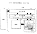
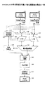
図2は、コンピュータシステムの構成の一例を示す図である。図2に示すコンピュータシステムは、プロセッサ110及びメモリ111を含む。演算処理装置としてのプロセッサ110は、2次キャッシュ部112、1次キャッシュ部113、制御部114、及び演算部115を含む。1次キャッシュ部113は、命令キャッシュ113A及びデータキャッシュ113Bを含む。演算部115は、レジスタ116、演算制御部117、及び演算器118を含む。演算器118には演算回路119が含まれる。なお図2及び以降の同様の図において、各ボックスで示される各機能ブロックと他の機能ブロックとの境界は、基本的には機能的な境界を示すものであり、物理的な位置の分離、電気的な信号の分離、制御論理的な分離等に対応するとは限らない。各機能ブロックは、他のブロックと物理的にある程度分離された1つのハードウェアモジュールであってもよいし、或いは他のブロックと物理的に一体となったハードウェアモジュール中の1つの機能を示したものであってもよい。各機能ブロックは、他のブロックと論理的にある程度分離された1つのモジュールであってもよいし、或いは他のブロックと論理的に一体となったモジュール中の1つの機能を示したものであってもよい。
FIG. 2 is a diagram illustrating an example of the configuration of a computer system. The computer system shown in FIG. 2 includes a
上記コンピュータシステムはCPU(Central Processing Unit)を用いた情報処理装置を模式化したものであり、このコンピュータシステムによりOracle−numberを演算するハードウエアを実現する。その際、システム構成を大幅に変更することなく、新機能を演算部115の機能として追加することが望まれる。そこで、新機能追加による変更部分が可能な限り少なくなるような実現方法をめざす。例えば、現状のCPUにおいては、演算器の入出力は、通常2オペランド入力且つ1出力の形であり、各オペランドのデータ幅は8バイト(64ビット)幅である。ハードウエアの変更量を小さく抑えるためには、この構造を大きく変えないことが望まれる。
The above computer system is a schematic representation of an information processing apparatus using a CPU (Central Processing Unit), and hardware for computing Oracle-number is realized by this computer system. At this time, it is desired to add a new function as a function of the
プロセッサ110では、1次キャッシュ部113及び2次キャッシュ部112を設けることにより、キャッシュメモリを多階層化した構成となっている。具体的には、1次キャッシュ部113と主記憶(メモリ111)との間に、主記憶よりも高速にアクセスできる2次キャッシュ部112を設けている。これにより、1次キャッシュ部113においてキャッシュミスが発生した場合に、主記憶にアクセスが必要になる頻度を低くして、キャッシュミス・ペナルティーを軽減することができる。
The
制御部114は、命令フェッチアドレスと命令フェッチリクエストとを1次命令キャッシュ40に発行し、この命令フェッチアドレスから命令をフェッチする。制御部114は、フェッチした命令をデコードした結果に従い演算部115を制御して、フェッチされた命令を実行する。演算制御部117は、制御部114の制御下で動作し、演算対象のレジスタ116からのデータを演算器118に供給したり、演算結果のデータを指定されたレジスタ116に格納したりする。また演算制御部117は、演算器118が実行する演算のタイプを指定する。更に演算制御部117は、アクセス先のアドレスを指定し、1次キャッシュ部113の当該アドレスに対してロード命令やストア命令を実行する。ロード命令により、指定アドレスから読み出されたデータは、指定されたレジスタ116に格納される。またストア命令により、指定されたレジスタ116のデータが、指定されたアドレスに書き込まれる。
The
まず、Oracle−numberのサブセットであるoraclenum64を定義する。oraclenum64は有効な仮数部の長さが7バイト以下であるようなOracle−numberである。 First, oraclenum64, which is a subset of Oracle-number, is defined. oraclenum64 is an Oracle-number whose effective mantissa has a length of 7 bytes or less.
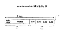
図3は、oraclenum64の構成を示す図である。oraclenum64の数を表現するデータ121は、8バイト長のレジスタに格納することができる。なお、符号及び指数部を含めた長さが8バイトに満たないOracle−numberをoraclenum64としてレジスタに格納する際には、図3にバイト122として示すようにデータを左詰めにして格納する。そして右側の余りの部分には、0X00の値を有するバイト123を余りのバイト数に等しい数だけ格納する。
FIG. 3 is a diagram showing the configuration of the oraclenum64.
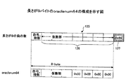
図4は、長さが9バイトのoraclenum64の構成を示す図である。図4に示すように、長さが9バイトである負のOracle−numberのデータ125は、7バイト長の仮数部126に続いて最後のバイト(第9バイト)にターミネータ127(0X66)が付加されている。このOracle−numberは、有効な仮数部126の長さが7バイトであるので、oraclenum64である。このことはoraclenum64を符号反転した数が必ずoraclenum64となるために必要である。
FIG. 4 is a diagram showing a configuration of oraclenum64 having a length of 9 bytes. As shown in FIG. 4, in the negative Oracle-
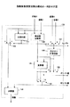
図5は、oraclenum64を直接演算対象とできる演算器の構成の一例である。図5の演算器は、図2の演算回路119の一部分に相当する。図5に示す演算器は、入力Xレジスタ131、入力Yレジスタ132、内部形式変換回路133及び134、指数仮数演算回路135、セレクタ136及び137、シフタ138及び139、指数加算器140、及び絶対値加算器141を含む。演算器は更に、正規化回路142、丸め回路143、外部形式変換回路144、及び出力Zレジスタ145を含む。内部形式変換回路133及び134と外部形式変換回路144とを工夫することで、例えばoraclenum64とIEEE754−decimal64との両方に対応させることも可能である。図5において、入力と出力は同形式同精度の浮動小数点数とする。入力データは正規化されていなくてもよい。出力データは正規化される。入力データはoraclenum64フォーマットとし、正規化されていないデータも解釈可能である。出力データはoraclenum64フォーマットの通りに出力される。
FIG. 5 is an example of the configuration of an arithmetic unit that can directly calculate the oraclenum64. The arithmetic unit in FIG. 5 corresponds to a part of the arithmetic circuit 119 in FIG. 5 includes an
内部形式変換回路133及び134により、入力を符号部、指数部、及び仮数部に分割し、入力の値表現を内部形式に変換する。入力Xの符号、指数、仮数をそれぞれ符号X、指数X、仮数Xとする。入力Yの符号、指数、仮数をそれぞれ符号Y、指数Y、仮数Yとする。
Internal
指数仮数演算回路135が、指数X及び指数Yと、仮数X及び仮数Yとを受け取る。指数仮数演算回路135は、指数Xと指数Yの大小比較をする。大小比較の結果に基づいて、指数仮数演算回路135は、指数の大きい側の仮数(第1の仮数)がシフタ138に入力され、且つ、指数の小さい側の仮数(第2の仮数)がシフタ139に入力されるように、セレクト信号を生成する。指数仮数演算回路135は、指数Xと指数Yとの差の絶対値と第1の仮数の先行ゼロ計数値とを比較し、指数Xと指数Yとの差の絶対値の方が大きい場合は、第1の仮数の先行ゼロ計数値をシフタ138の左シフト量として出力する。指数Xと指数Yとの差の絶対値の方が小さい場合は、指数仮数演算回路135は、指数Xと指数Yとの差の絶対値をシフタ138の左シフト量として出力する。ここで、先行ゼロ計数値とは、仮数部の最上位桁から連続するゼロを計数した値をいう。
An exponent
指数仮数演算回路135は、指数Xと指数Yとの差の絶対値と第1の仮数の先行ゼロ計数値とを比較し、指数Xと指数Yとの差の絶対値の方が大きい場合は、指数Xと指数Yとの差の絶対値から第1の仮数の先行ゼロ計数値を減算した値をシフタ139の右シフト量として出力する。指数Xと指数Yとの差の絶対値の方が小さい場合は、指数仮数演算回路135は、ゼロをシフタ139の右シフト量として出力する。指数仮数演算回路135は更に、指数の小さい側に上述の右シフト量を加算した値を指数として出力する。
The exponent
シフタ138は、入力されたシフト量に基づき、入力された仮数を左シフトする。シフタ139は、入力されたシフト量に基づき、入力された仮数を右シフトする。各シフタのシフト結果は絶対値加算器141に入力される。
The
減算の場合は、片方の仮数が反転され、絶対値加算器141にキャリーが入力される。絶対値加算器141による加算の結果桁あふれが生じた場合は、1桁右にシフトした値が出力される。同時に、絶対値加算器141から指数加算器140にキャリーが送られ、送られたキャリーが指数に加算される。
In the case of subtraction, one mantissa is inverted and a carry is input to the
絶対値加算器141による加算の結果桁落ちが生じた場合は、1桁左にシフトした値が出力される。同時に、絶対値加算器141から指数加算器140に桁落ちを示す信号が送られ、指数から減算される。乗算や除算の場合は、加算結果を再利用するループ演算回路を用いてもよい。
When a digit loss occurs as a result of addition by the
正規化回路142が加算結果を受け取り、正規化演算結果を出力する。丸め回路143が、正規化演算結果を丸める。外部形式変換回路144は、丸め処理後の正規化演算結果を外部形式に変換し、出力Zレジスタ145に出力する。
The
図6は、指数仮数演算回路の構成の一例を示す図である。図6に示す指数仮数演算回路135は、比較回路151、絶対値加算器152、セレクタ153及び154、加算器155、先行ゼロ計数回路156、セレクタ157及び158、及び加算器159を含む。
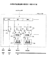
FIG. 6 is a diagram illustrating an example of the configuration of the exponent mantissa arithmetic circuit. The exponent
比較回路151は、指数Xと指数Yとの大小比較をし、指数の大きい側の仮数(第1の仮数)がシフタ138に入力され、指数の小さい側の仮数(第2の仮数)がシフタ139に入力されるように、セレクト信号を生成する。絶対値加算器152は、指数Xと指数Yの差の絶対値を計算する。先行ゼロ計数回路156は、セレクトされた仮数の先行ゼロを計数する。加算器155は、指数Xと指数Yとの差の絶対値とセレクトされた仮数の先行ゼロ計数値とを比較し、比較結果に応じたセレクト信号を出力する。セレクタ158は、差の絶対値の方が大きい場合、先行ゼロ計数値をシフタ138の左シフト量として出力する。セレクタ158は、差の絶対値の方が小さい場合、差の絶対値をシフタ138の左シフト量として出力する。
The
セレクタ157は、差の絶対値の方が大きい場合、差の絶対値から先行ゼロ計数値を減算した値をシフタ139の右シフト量として出力する。セレクタ157は、差の絶対値の方が小さい場合、ゼロをシフタ139の右シフト量として出力する。
When the absolute value of the difference is larger, the
加算器159は、セレクタ153から小さい側の指数を受け取る。加算器159は、受け取った小さい側の指数に上述の右シフト量を加算して求めた値を、指数として出力する。
The
図7は、正規化回路の構成の一例を示す図である。図7に示す正規化回路142は、先行ゼロ計数回路160、シフト量補正回路161、左シフタ162、指数演算器163、ビットシフタ164及び165、及びセレクタ166を含む。
FIG. 7 is a diagram illustrating an example of the configuration of the normalization circuit. The
仮数は桁あふれを考慮する場合は最上位側が1桁多い幅で入力される。先行ゼロ計数回路160は、最上位桁の1つ上の桁を除いた仮数を受け取り、先行ゼロを計数することにより得られた計数値を出力する。シフト量補正回路161は、先行ゼロ計数値と指数の最下位ビットとを受け取る。先行ゼロ計数値の最下位ビット(偶奇を表す)と指数の最下位ビットとをXOR(排他的論理和)した値が1の場合、シフト量補正回路161は、先行ゼロ計数値から1を減じた値を左シフト量として出力する。また上記XOR値が0の場合、シフト量補正回路161は、先行ゼロ計数値を左シフト量として出力する。
The mantissa is input with a width one digit higher on the most significant side when overflow is considered. The leading zero
左シフタ162は、最上位桁の1つ上の桁を除いた仮数とシフト量とを受け取り、指定されたシフト量だけ仮数を左シフトした値を出力する。セレクタ166は、入力の最上位桁の1つ上の桁が0の場合、左シフタ162が出力する左シフトした結果を選択する。またセレクタ166は、入力の最上位桁の1つ上の桁が1であり且つ指数の最下位ビットが0の場合、最上位桁の1つ上の桁を含む入力仮数を2桁右シフトした値を選択する。またセレクタ166は、入力の最上位桁の1つ上の桁が1であり且つ指数の最下位ビットが1の場合、最上位桁の1つ上の桁を含む入力仮数を1桁右シフトした値を選択する。セレクタ166の選択した値は、仮数として出力される。
The
指数演算器163は、指数、シフト量、及び入力仮数の最上位桁を受け取る。入力仮数の最上位桁が0の場合、指数演算器163は、指数からシフト量を減算した結果を指数として出力する。入力仮数の最上位桁が1であり且つ指数の最下位ビットが0の場合、指数演算器163は、指数に2を加算した結果を指数として出力する。入力仮数の最上位桁が1であり且つ指数の最下位ビットが1の場合、指数演算器163は、指数に1を加算した結果を指数として出力する。
The
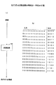
図8は、先行ゼロ計数回路の構成の一例を示す図である。図8(a)に示すように、先行ゼロ計数回路は、変換回路160を含む。変換回路160は仮数を入力データとして受け取り、図8(b)に示すテーブルに従い入力データから出力データを生成する。この出力データが先行ゼロ計数値であり、2進数により計数値が表わされる。テーブルでは、一番左側のXはゼロ以外の値を表し、それ以外のXはドントケアを表す。0は計数対象となるゼロを表す。
FIG. 8 is a diagram illustrating an example of the configuration of the leading zero counting circuit. As shown in FIG. 8A, the leading zero counting circuit includes a
図9は、内部形式変換回路の構成の一例を示す図である。図9に示す内部形式変換回路133又は134は、セレクタ170乃至174、加算器175及び176、及び2進10進変換回路177及び178を含む。
FIG. 9 is a diagram illustrating an example of the configuration of the internal format conversion circuit. The internal
入力されたデータは、符号部S、指数部EXP、仮数部M01、M02、・・・に分割される。符号部Sは1ビットであり、符号としてそのまま出力される。符号は1の場合に正を表す。 The input data is divided into a sign part S, an exponent part EXP, a mantissa part M01, M02,. The code part S has 1 bit and is output as it is as a code. The sign is positive when it is 1.
指数部EXPは7ビットである。セレクタ170は、符号が1の場合、指数部EXPをそのまま指数として出力する。またセレクタ170は、符号が0の場合、指数部EXPを反転した値を指数として出力する。
The exponent EXP is 7 bits. When the sign is 1,
仮数部M01、M02、・・・の各々は、8ビット長のデータである。セレクタ171は、符号が1の場合は仮数を選択し、符号が0の場合は仮数の反転値を選択する。この選択値が加算器175の一方の入力となる。またセレクタ172は、符号が1の場合は−1を選択し、符号が0の場合は+101を選択する。この選択値が加算器175のもう一方の入力となる。また、符号が0の場合には、加算器175にキャリーが入力される。セレクタ173及び174並びに加算器176についても同様である。
Each of the mantissa parts M01, M02,... Is 8-bit data. The
加算器175及び176の出力が、それぞれ、2進10進変換回路177及び178により2進形式からBCD形式の値に変換され、BCD変換後の値が仮数として出力される。ただし、加算器からのCOが0の場合には、変換後のBCD値は強制的にゼロとなる。
The outputs of the
図10は、外部形式変換回路の構成の一例を示す図である。図10に示す外部形式変換回路144は、デコーダ180、10進2進変換回路181及び182、セレクタ183乃至187、及び加算器188及び189を含む。図10では、2つの仮数部BCD01、BCD02のみに対する回路部分が明示的に示されるが、仮数部の数が2以上の場合には、同様の回路部分がそれらの仮数部に対して設けられる。
FIG. 10 is a diagram showing an example of the configuration of the external format conversion circuit. The external
入力された1ビットの符号部は、そのまま符号として出力される。符号は1の場合に正を表す。指数部の入出力は7ビットである。セレクタ値183により、符号が1の場合は入力指数がそのまま出力指数となり、符号が0の場合は入力指数の反転値が出力指数となる。仮数部BCD01、BCD02、・・・は、1つの入力BCDあたり8ビットであり、10進2進変換回路181、182、・・・によりBCDから2進数に変換される。
The input 1-bit code part is output as a code as it is. The sign is positive when it is 1. The input / output of the exponent part is 7 bits. According to the
ターミネータ選択信号を受け取るデコーダ180は、終端の桁を現すターミネータ桁を選択するターミネータ桁セレクト信号を生成する。このターミネータ桁セレクト信号は、後段のセレクタ184、185、・・・に分配される。
The
加算器188、189、・・・の各々において、一方の入力には、符号が1の場合は仮数がそのまま入力され、符号が0の場合は仮数の反転値が入力される。但し、ターミネータ桁セレクト信号が1の場合は、ゼロが選択されて入力される。もう一方の入力には、符号が1の場合は+1が入力され、符号が0の場合は+101が入力される。但し、ターミネータ桁セレクト信号が1の場合は、+101が選択されて入力される。ここで実際に加算したい値は+102であるが、+101にキャリーインが加算されることで、+102を加算することと同等になる。また、符号が0の場合には加算器にキャリーインが入力される。加算器188、189、・・・の出力が、各桁の仮数として出力される。
In each of the
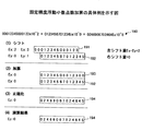
図11は、固定精度浮動小数点数加算の具体例を示す図である。図11において、入力Xの指数をEx、入力Yの指数をEy、入力Xの先行ゼロ計数値をLx、入力Yの先行ゼロ計数値をLyとする。また出力Zの指数をEzとする。可能な限り高い演算精度を保持するとき、指数値の大きい側を左シフトして桁合わせを行う。但し、先行ゼロの桁数より多く左シフトすることは、上位桁が欠落してしまうため、桁合わせに必要な左シフト量Ex−Eyが先行ゼロの桁数を上回る場合は、指数値の小さい側を右シフトすることで、桁合わせを行う。このためにEx−Eyを計算し、Lxと比較する。図11に示す具体例ではLxのほうが大きい。即ち、左シフト量Ex−Eyが先行ゼロの数内に収まるので、入力Xの仮数191のみ左シフトされる。入力Yの仮数192は右シフトされない。左シフト量はEx−Eyであり、右シフト量は0である。
FIG. 11 is a diagram illustrating a specific example of fixed-precision floating-point number addition. In FIG. 11, the exponent of the input X is Ex, the exponent of the input Y is Ey, the leading zero count value of the input X is Lx, and the leading zero count value of the input Y is Ly. The exponent of the output Z is Ez. To maintain the highest possible calculation accuracy, shift the left side of the larger exponent value to perform digit alignment. However, shifting to the left more than the number of leading zeros results in the loss of the upper digits, so if the left shift amount Ex-Ey required for digit alignment exceeds the number of leading zeros, the exponent value is small. Align the digits by shifting the side to the right. For this purpose, Ex-Ey is calculated and compared with Lx. In the specific example shown in FIG. 11, Lx is larger. That is, since the left shift amount Ex-Ey falls within the number of leading zeros, only the
このようにして桁合わせされた数同士、即ち仮数191を左シフトして得られた仮数193と仮数192とを加算する。更に、加算結果194を正規化し、先行ゼロ計数値が1以上の場合はその分だけ左シフトを行い、桁あふれがある場合には1桁分の右シフトを行う。但し、左シフトした結果指数が奇数になる場合は、左シフト量を1減らす。または右シフトした結果指数が奇数になる場合は、右シフト量を1増やす。指数は、左右シフト量に合わせて調整する。左シフトした場合は左シフト量を指数から減算し、右シフトした場合は右シフト量を指数に加算する。本具体例では1桁左シフトが必要だが、指数が0から1となり奇数になるので、左シフト量は1減らされて0となり、指数は0のままである。その結果、正規化により加算結果は変化せず、そのまま演算結果の仮数194及び対応する指数Ezを含む演算結果として出力される。
The numbers thus aligned, that is, the
図12は、固定精度浮動小数点数加算の別の具体例を示す図である。この具体例では必要な左シフト量Ex−EyよりもLxのほうが小さい。この場合、必要な左シフト量Ex−Eyが先行ゼロ計数値の数内に収まらないので、入力Xの仮数201をLx分だけ左シフトし、左シフトしきれなかった分だけ入力Yの仮数202を右シフトする。即ち、左シフト量はLxであり、右シフト量は(Ex−Ey)−Lxである。
FIG. 12 is a diagram showing another specific example of addition of fixed-precision floating-point numbers. In this specific example, Lx is smaller than the required left shift amount Ex−Ey. In this case, since the necessary left shift amount Ex-Ey does not fall within the number of leading zero count values, the mantissa 201 of the input X is shifted to the left by Lx, and the
このようにして桁合わせされた数同士、即ち仮数201を左シフトして得られた仮数203と仮数202を右シフトして得られた仮数204とを加算する。このとき、右シフトによって溢れた桁も保持する。更に、加算結果205を正規化し、先行ゼロ計数値が1以上の場合はその分だけ左シフトを行い、桁あふれがある場合には1桁分の右シフトを行う。但し、左シフトした結果指数が奇数になる場合は、左シフト量を1減らす。または右シフトした結果指数が奇数になる場合は、右シフト量を1増やす。指数は、左右シフト量に合わせて調整する。左シフトした場合は左シフト量を指数から減算し、右シフトした場合は右シフト量を指数に加算する。本具体例では1桁右シフトが必要だが、指数Ezが2から3となり奇数になるので、右シフト量は1増やされて2となり、指数Ezは2から4となる。
The numbers thus aligned, that is, the
その後、正規化した結果206に対して丸め処理を実行する。この例においては右にはみ出した桁を四捨五入することにより実行される。このようにして丸められた結果が、丸め結果の仮数207及び対応する指数Ezを含む演算結果として出力される。
Thereafter, a rounding process is performed on the normalized
以下に、1つのOracle−numberを複数のoraclenum64を含む組により表現する方法について説明する。 Hereinafter, a method for expressing one Oracle-number by a set including a plurality of oraclenum64 will be described.
最大で21バイト長のOracle−numberの計算を、oraclenum64 演算ハードウエアを用いて実現するためには、Oracle−numberを複数のoraclenum64を含む組で表現する必要がある。 In order to realize calculation of an Oracle-number having a maximum length of 21 bytes using oraclenum64 arithmetic hardware, it is necessary to express an oracle-number as a set including a plurality of oraclenum64.
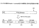
図13は、21バイト長のOracle−numberを3つの部分に分ける方法を示す図である。図22に示されるように、最大20バイト長の仮数部210は、7バイトの仮数部211、7バイトの仮数部212、及び6バイトの仮数部213に分割される。
FIG. 13 is a diagram illustrating a method of dividing an Oracle-number having a length of 21 bytes into three parts. As shown in FIG. 22, the
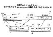
図14は、分割された3つの仮数部にそれぞれ対応するoraclenum64数を生成する方法を示す図である。a0については、元のOracle−numberの先頭8バイト部分(1バイトの符号及び指数部214+7バイトの仮数部211)を切り出してくるだけで、oraclenum64形式の数が得られる。a1及びa2については、元のOracle−numberの第1バイト(符号及び指数部214)を加工する必要がある。具体的には、元のOracle−numberの基数10での指数をEとして、a1の指数E1=E−14とすることで、a1についての1バイトの符号及び指数部215を生成する。この符号及び指数部215に7バイトの仮数部212を付加して、a1に相当するoraclenum64形式の数が得られる。またa2の指数E2=E−28とすることで、a2についての1バイトの符号及び指数部216を生成する。この符号及び指数部216に6バイトの仮数部213及び1バイトの"0"を付加して、a2に相当するoraclenum64形式の数が得られる。このようにして得られた3つのoraclenum64の組を、以下においてtriple−oraclenum64と呼ぶ。
FIG. 14 is a diagram illustrating a method of generating oraclenum64 numbers respectively corresponding to the three divided mantissa parts. For a0, a number in the oraclenum64 format can be obtained simply by cutting out the first 8 bytes of the original Oracle-number (the sign of 1 byte and the
以下に、triple−oraclenum64形式に対する四則演算をoraclenum64演算器により実行する構成について説明する。まず、最も基本となる、oraclenum64の数同士の正確な和を求める演算について説明する。以下に示すtwo−sum(2数の和)は、非特許文献1にformula(4.16)として示されているものであり、同様のものが非特許文献2のp.18、及び、非特許文献3のalgorithm4に示されている。
Hereinafter, a configuration in which four arithmetic operations for the triple-oraclenum64 format are executed by the oraclenum64 calculator will be described. First, the most basic operation for obtaining an accurate sum of the numbers of oraclenum64 will be described. The following two-sum (sum of two numbers) is shown as “formula (4.16)” in
Two_sum(X, Y)
z = fl(X + Y)
w = fl(z - X)
v = fl(z - w)
z1 = fl(Y - w)
z2 = fl(v - X)
zz = fl(z1 - z2)
return(z, zz)
ここでfl(X+Y)は、X+Yの真の値を、浮動小数点数にマッピングした結果、即ち浮動小数点形式の限られた精度内で表現した結果を示す。上記のTwo_sumによって得られる2数z及びzzは、正確な意味においてz+zz=X+Yを満たす。zはX+Yの最重要部(most significant part)を固定精度浮動小数点の精度内で表現した値であり、zzは固定精度浮動小数点の精度で表現しきれなかった残余分を表す。
Two_sum (X, Y)
z = fl (X + Y)
w = fl (z-X)
v = fl (z-w)
z1 = fl (Y-w)
z2 = fl (v-X)
zz = fl (z1-z2)
return (z, zz)
Here, fl (X + Y) represents the result of mapping the true value of X + Y to a floating-point number, that is, the result expressed within the limited precision of the floating-point format. The two numbers z and zz obtained by the above Two_sum satisfy z + zz = X + Y in an accurate sense. z is a value representing the most significant part of X + Y within the precision of the fixed precision floating point, and zz represents the remainder that cannot be expressed with the precision of the fixed precision floating point.
マッピング時に発生する丸め処理方法として、10進数で代表的な丸め方法である四捨五入を例に取り説明する。簡単のために固定精度浮動小数点数の精度は10進2桁とする。この場合、20000と−1との2数の和は、上記のTwo_sumにより以下のように計算される。 As a rounding method that occurs at the time of mapping, a rounding method that is a representative rounding method using decimal numbers will be described as an example. For simplicity, the precision of fixed-precision floating-point numbers is assumed to be two decimal digits. In this case, the sum of the two numbers 20000 and −1 is calculated as follows using the above Two_sum.
X = 20000
Y = -1
z = fl(X+Y) = 20000
w = fl(z−X) = 0
v = fl(z−w) = 20000
z1 = fl(Y−w) = -1
z2 = fl(v−X) = 0
zz = fl(z1−z2) = -1
この例のように、一般に、two_sumの結果であるzとzzは異符合となり得る。一方、丸め方法を切り捨てとした場合は、XとYとで有効桁がオーバーラップしない場合には、以下の例のようにz+zzがX+Yと等しくならない場合がある。
X = 20000
Y = -1
z = fl (X + Y) = 20000
w = fl (z-X) = 0
v = fl (z-w) = 20000
z1 = fl (Y−w) = − 1
z2 = fl (v−X) = 0
zz = fl (z1-z2) =-1
As in this example, in general, z and zz, which are the result of two_sum, can be different signs. On the other hand, when the rounding method is rounded down, if the significant digits do not overlap between X and Y, z + zz may not be equal to X + Y as in the following example.
X = 20000
Y = -1
z = fl(X+Y) = 19000
w = fl(z−X) = -1000
v = fl(z−w) = 20000
z1 = fl(Y−w) = 990
z2 = fl(v−X) = 0
zz = fl(z1−z2) = 990
ここで、Xの絶対値がYの絶対値より大きいか等しいと仮定し、更に以下のような新たな丸め処理を行うことにより、zzの算出が容易になることを示す。
X = 20000
Y = -1
z = fl (X + Y) = 19000
w = fl (z-X) = -1000
v = fl (z-w) = 20000
z1 = fl (Y−w) = 990
z2 = fl (v−X) = 0
zz = fl (z1-z2) = 990
Here, it is assumed that the absolute value of X is greater than or equal to the absolute value of Y, and the following new rounding process is performed to facilitate the calculation of zz.
(1)XとYとの間で有効桁のオーバーラップが無い場合は四捨五入する
(2)XとYとの間で有効桁のオーバーラップがある場合は切り捨てる
但し、XとYとの間で有効桁がオーバーラップしていない場合であっても、XとYとの間で有効桁が連続している場合は(2)に含めることにする。
(1) Round off if there is no significant digit overlap between X and Y. (2) Truncate if there is significant digit overlap between X and Y. However, between X and Y. Even if the effective digits do not overlap, if the effective digits are continuous between X and Y, they are included in (2).
具体的な例を用いて、上記のような丸め処理を適用することの効果を説明する。前述の場合と同様に固定精度浮動小数点数の精度は10進2桁である。また、XとYとの間で有効桁が連続している場合の例を示す。まず上記の特殊な丸め処理ではなく、flが常に四捨五入の丸め処理を行なう場合には、以下のようになる。 The effect of applying the rounding process as described above will be described using a specific example. As in the previous case, the precision of the fixed-precision floating-point number is two decimal digits. Further, an example in which valid digits are continuous between X and Y is shown. First, instead of the above-described special rounding process, when fl always rounds off, the following is performed.
X = 2000
Y = 52
z = 2100
w = 100
v = 2000
z1 = -48
z2 = 0
zz = -48
それに対して、上記の新たな丸め処理を用いる場合は、以下のようになる。
X = 2000
Y = 52
z = 2100
w = 100
v = 2000
z1 = -48
z2 = 0
zz = -48
On the other hand, when the above-mentioned new rounding process is used, it is as follows.
X = 2000
Y = 52
z = 2000
w = 0
v = 2000
z1 = 52
z2 = 0
zz = 52
上記の新たな丸め処理を用いることにより、以下の効果が得られる。まず(1)の場合には、オーバーラップがないので、X+Yを行った後の四捨五入による丸め処理や、四捨五入によって発生したwを補正するために必要であったz1を求める演算処理がなくなる。また(2)の場合には、X+Yの精度は有効桁数の2倍以下であることが保証され、丸め処理が切り捨てのみとなるため、演算を実行するハードウエアの実現が容易となる。
X = 2000
Y = 52
z = 2000
w = 0
v = 2000
z1 = 52
z2 = 0
zz = 52
By using the above new rounding process, the following effects can be obtained. First, in the case of (1), since there is no overlap, there is no rounding process by rounding after performing X + Y, and no arithmetic process for obtaining z1 necessary for correcting w generated by rounding off. In the case of (2), the accuracy of X + Y is guaranteed to be less than twice the number of significant digits, and the rounding process is only rounded down, which makes it easy to implement hardware that performs the operation.
以上のことから、2つの入力値の絶対値を比較して、その比較結果に応じて上記の(1)又は(2)の場合分けを行ない、新たな丸め処理を実行すれば、zzの算出が容易となる。また更に、z,zzを求める演算get_z(x,y),get_zz(x,y)をハードウエアで実行する回路を設ければ、以下に示すように、two_sumを高速に処理することが可能となる。 From the above, if absolute values of two input values are compared, the case of (1) or (2) above is performed according to the comparison result, and a new rounding process is performed, so that zz is calculated. Becomes easy. Furthermore, if a circuit for executing operations get_z (x, y) and get_zz (x, y) for obtaining z and zz by hardware is provided, two_sum can be processed at high speed as shown below. Become.
Two_sum_fast(x, y)
z = get_z(x, y)
zz = get_zz(x, y)
return(z, zz)
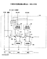
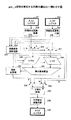
図15は、get_z演算を実現する回路の構成の一例を示す図である。図15の演算器は、図2の演算回路119の一部分に相当する。図15に示す演算器は、入力Xレジスタ221、入力Yレジスタ222、内部形式変換回路223及び224、指数仮数演算回路225、セレクタ226及び227、シフタ228及び229、指数加算器230、及び絶対値加算器231を含む。演算器は更に、セレクタ232及び233、正規化回路234、外部形式変換回路235、及び出力Zレジスタ236を含む。図15において、図5に示す回路と同一又は対応する構成要素は同一又は対応する名称で参照する。図15において、入力と出力は同形式同精度の浮動小数点数とする。入力データは正規化されていなくてもよい。出力データは正規化される。入力データはoraclenum64フォーマットとし、正規化されていないデータも解釈可能である。出力データはoraclenum64フォーマットの通りに出力される。
Two_sum_fast (x, y)
z = get_z (x, y)
zz = get_zz (x, y)
return (z, zz)
FIG. 15 is a diagram illustrating an example of a configuration of a circuit that implements the get_z operation. The computing unit in FIG. 15 corresponds to a part of the computing circuit 119 in FIG. 15 includes an
内部形式変換回路223及び224により、入力を符号部、指数部、及び仮数部に分割し、入力の値表現を内部形式に変換する。入力Xの符号、指数、仮数をそれぞれ符号X、指数X、仮数Xとする。入力Yの符号、指数、仮数をそれぞれ符号Y、指数Y、仮数Yとする。
Internal
指数仮数演算回路225が、指数X及び指数Yと、仮数X及び仮数Yとを受け取る。指数仮数演算回路225は、指数Xと指数Yの大小比較をする。大小比較の結果に基づいて、指数仮数演算回路225は、指数の大きい側の仮数(第1の仮数)がシフタ228に入力され、且つ、指数の小さい側の仮数(第2の仮数)がシフタ229に入力されるように、セレクト信号を生成する。指数仮数演算回路225は、指数Xと指数Yとの差の絶対値と第1の仮数の先行ゼロ計数値とを比較し、前者の方が大きい場合は、後者をシフタ228の左シフト量として出力する。前者の方が小さい場合は、指数仮数演算回路225は、前者をシフタ228の左シフト量として出力する。
The exponent
指数仮数演算回路225は、指数Xと指数Yとの差の絶対値と第1の仮数の先行ゼロ計数値とを比較し、指数Xと指数Yとの差の絶対値の方が大きい場合は、指数Xと指数Yとの差の絶対値から第1の仮数の先行ゼロ計数値を減算した値をシフタ229の右シフト量として出力する。指数Xと指数Yとの差の絶対値の方が小さい場合は、指数仮数演算回路225は、ゼロをシフタ229の右シフト量として出力する。指数仮数演算回路225は更に、指数の小さい側に上述の右シフト量を加算した値を指数として出力する。
The exponent
指数仮数演算回路225は更に、(指数X−仮数Xの先行ゼロ計数値)−(指数Y−仮数Yの先行ゼロ計数値)の絶対値が14以上であるか否かを判定する。この絶対値が14以上である場合、指数仮数演算回路225は、第1の仮数と第1の仮数に対応する指数とがセレクタ232及び233により選択されるように、セレクト信号を生成する。これにより、上記絶対値が14以上である場合には、第1の仮数が、シフタ228及び絶対値加算器231をバイパスして、正規化回路234に入力されることになる。
The exponent
シフタ228は、入力されたシフト量に基づき、入力された仮数を左シフトする。シフタ229は、入力されたシフト量に基づき、入力された仮数を右シフトする。各シフタのシフト結果は絶対値加算器231に入力される。
The
減算の場合は、片方の仮数が反転され、絶対値加算器231にキャリーが入力される。絶対値加算器231による加算の結果桁あふれが生じた場合は、1桁右にシフトした値が出力される。同時に、絶対値加算器231から指数加算器230にキャリーアウトが送られ、指数に加算される。
In the case of subtraction, one mantissa is inverted and a carry is input to the
絶対値加算器231による加算の結果桁落ちが生じた場合は、1桁左にシフトした値が出力される。同時に、絶対値加算器231から指数加算器230に桁落ちを示す信号が送られ、指数から減算される。
If a digit loss occurs as a result of addition by the
セレクタ232及び233は、指数仮数演算回路225によって生成されたセレクト信号に応じて、加算結果の指数及び仮数、又は、第1の仮数及びそれに対応する指数を選択する。正規化回路234が、セレクタ232及び233により選択された指数及び仮数を受け取り、正規化演算結果を出力する。外部形式変換回路235は、正規化演算結果を外部形式に変換し、出力Zレジスタ236に出力する。
The
図16は、get_z演算の具体例を示す図である。図16において、入力Xの指数をEx、入力Yの指数をEy、入力Xの先行ゼロ計数値をLx、出力Zの指数をEzとする。この例において実行する演算は、図16に示すget_z演算240である。可能な限り高い演算精度を保持するとき、指数値の大きい側を左シフトして桁合わせを行う。但し、先行ゼロの桁数より多く左シフトすることは、上位桁が欠落してしまうために不可能であるので、桁合わせに必要な左シフト量Ex−Eyが先行ゼロの桁数を上回る場合は、指数値の小さい側を右シフトすることで、桁合わせを行う。このためにEx−Eyを計算し、Lxと比較する。図16に示す具体例ではLxのほうが大きい。即ち、左シフト量Ex−Eyが先行ゼロの数内に収まるので、入力Xの仮数241のみ左シフトされる。入力Yの仮数242は右シフトされない。左シフト量はEx−Eyであり、右シフト量は0である。
FIG. 16 is a diagram illustrating a specific example of the get_z calculation. In FIG. 16, the exponent of the input X is Ex, the exponent of the input Y is Ey, the leading zero count value of the input X is Lx, and the exponent of the output Z is Ez. The calculation executed in this example is a
このようにして桁合わせされた数同士、即ち仮数241を左シフトして得られた仮数243と仮数242のままである仮数244とを加算する。更に、加算結果245を正規化し、先行ゼロ計数値が1以上の場合は先行ゼロ計数値だけ左シフトを行い、桁あふれがある場合には1桁分の右シフトを行う。但し、左シフトした結果指数が奇数になる場合は、左シフト量を1減らす。または右シフトした結果指数が奇数になる場合は、右シフト量を1増やす。指数は、左右シフト量に合わせて調整する。左シフトした場合は左シフト量を指数から減算し、右シフトした場合は右シフト量を指数に加算する。本具体例では1桁左シフトが必要だが、指数が0から1となり奇数になるので、左シフト量は1減らされて0となり、指数は0のままである。この例では、正規化による変化はない。更に正規化結果の仮数246の上位桁を選択する。例えば入力フォーマットの仮数が14桁である場合は、最上位から14桁を上位桁、最上位から15桁目以降を下位桁とする。
The numbers thus aligned, that is, the
上記の演算の結果、仮数247及び対応する指数Ezを含む演算結果が出力される。
As a result of the above calculation, a calculation result including the
図17は、get_z演算の別の具体例を示す図である。この例において実行する演算は、図17に示すget_z演算250である。可能な限り高い演算精度を保持するとき、指数値の大きい側を左シフトして桁合わせを行う。但し、先行ゼロの桁数より多く左シフトすることは、上位桁が欠落してしまうために不可能であるので、桁合わせに必要な左シフト量Ex−Eyが先行ゼロの桁数を上回る場合は、指数値の小さい側を右シフトすることで、桁合わせを行う。このためにEx−Eyを計算し、Lxと比較する。図17に示す具体例ではLxのほうが小さい。即ち、左シフト量Ex−Eyが先行ゼロの数内に収まらないので、入力Xの仮数251をLx分だけ左シフトし、左シフトしきれなかった分だけ入力Yの仮数252を右シフトする。即ち、左シフト量はLxであり、右シフト量は(Ex−Ey)−Lxである。
FIG. 17 is a diagram illustrating another specific example of the get_z calculation. The calculation executed in this example is a
このようにして桁合わせされた数同士、即ち仮数251を左シフトして得られた仮数253と仮数252を右シフトして得られた仮数254とを加算する。このとき、右シフトによって溢れた桁も保持する。更に、加算結果255を正規化し、先行ゼロが1以上の場合はその分だけ左シフトを行い、桁あふれがある場合には1桁分の右シフトを行う。但し、左シフトした結果指数が奇数になる場合は、左シフト量を1減らす。または右シフトした結果指数が奇数になる場合は、右シフト量を1増やす。指数は、左右シフト量に合わせて調整する。左シフトした場合は左シフト量を指数から減算し、右シフトした場合は右シフト量を指数に加算する。本具体例では1桁右シフトが必要だが、指数が2から3となり奇数になるので、右シフト量は1増やされて2となり、指数は2から4となる。このようにして得られた正規化の結果の仮数256の上位桁を選択する。例えば入力フォーマットの仮数が14桁である場合は、最上位から14桁を上位桁、最上位から15桁目以降を下位桁とする。
The numbers thus aligned, that is, the
上記の演算の結果、演算結果の仮数257が出力されるとともに、対応する指数Ezが演算結果の指数として出力される。
As a result of the above calculation, the
図18は、get_z演算の更に別の具体例を示す図である。この例において実行する演算は、図18に示すget_z演算260である。可能な限り高い演算精度を保持するとき、指数値の大きい側を左シフトして桁合わせを行う。但し、先行ゼロの桁数より多く左シフトすることは、上位桁が欠落してしまうため、桁合わせに必要な左シフト量Ex−Eyが先行ゼロの桁数を上回る場合は、指数値の小さい側を右シフトすることで、桁合わせを行う。但し、桁合わせした結果、2つの入力の間に14桁以上の差がある場合、即ち、重なりが全くない場合には、実際に演算処理を実行しなくとも演算結果を求めることが可能である。get_zは演算結果の上位側を求める演算であり、2入力の重なりがない場合には値の大きい側がそのまま上位側となるからである。
FIG. 18 is a diagram illustrating still another specific example of the get_z calculation. The calculation executed in this example is a
この条件を満たすか否かを確認するため、(Ex−Lx)−(Ey−Ly)を計算し、計算結果が14以上の場合には上記の場合に該当すると判定する。ここで値14は、使用フォーマットにおける仮数の桁数である。この具体例では上記の場合に該当し、仮数261と仮数262との間に重なりが存在しない。この場合、仮数261がそのままバイパスされて加算結果として取り扱われる。
In order to check whether or not this condition is satisfied, (Ex−Lx) − (Ey−Ly) is calculated, and when the calculation result is 14 or more, it is determined that the above case is satisfied. Here, the
更にバイパスされた結果263を正規化し、先行ゼロ計数値が1以上の場合は先行ゼロ計数値だけ左シフトを行い、桁あふれがある場合には1桁分の右シフトを行う。但し、左シフトした結果指数が奇数になる場合は、左シフト量を1減らす。または右シフトした結果指数が奇数になる場合は、右シフト量を1増やす。指数は、左右シフト量に合わせて調整する。左シフトした場合は左シフト量を指数から減算し、右シフトした場合は右シフト量を指数に加算する。本具体例では3桁左シフトが必要だが、指数が16から13となり奇数になるので、左シフト量は1減らされて2となり、指数は16から14となる。このようにして得られた正規化の結果が、そのまま演算結果の仮数264及び対応する指数Ezを含む演算結果として出力される。
Further, the bypassed
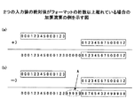
なおzzは固定精度の範囲で表現しきれなかった加算演算の残余の部分を表すが、例えば乗算の場合にはzzを出力する命令は一般的である。乗算の場合、zとzzは互いの桁が連続した値である。しかし加算の場合は、2つの入力値の絶対値がフォーマットの桁数以上離れている場合は、zとzzは互いの桁が連続した値とならない。図19(a)に、2つの入力値の絶対値がフォーマットの桁数以上離れている場合の加算演算の例を示す。この第1のケースにおいては、通常のフローで演算を行いzzを出力してもよいが、値の重なりが全くないことを利用すると、演算をしなくとも絶対値の小さい側をそのままzzとすることができ、zzを容易に出力することが可能である。 Note that zz represents the remaining part of the addition operation that could not be expressed within a fixed precision range. For example, in the case of multiplication, an instruction that outputs zz is common. In the case of multiplication, z and zz are values having consecutive digits. However, in the case of addition, if the absolute values of the two input values are more than the number of digits in the format, z and zz do not have a continuous value. FIG. 19A shows an example of the addition operation when the absolute values of the two input values are separated from each other by the number of digits in the format. In this first case, calculation may be performed in a normal flow and zz may be output. However, if there is no overlap of values, the side having a smaller absolute value is used as it is without calculation. And zz can be output easily.
また乗算の場合は、入力の符号は演算結果の仮数の値には影響しないため、zzを求める際に符号を考慮する必要がない。しかし加算の場合は、上記のように2つの入力値の絶対値が離れているとき、互いに異なる符号を有する2つの数の加算(同符号の数同士の減算)において特別な処理が必要である。図19(b)に、2つの入力値の絶対値が離れている場合における互いに異なる符号を有する2つの数の加算演算の例を示す。この第2のケースにおいては、通常のフローで演算を行うと、2つの入力の間のゼロで埋められていた桁に、図19(b)にAとして示すように、桁下がりによってゼロ以外の値が発生する。その結果、zzを表すために必要な精度が、離れた桁数分だけ増えてしまうことになる。従って、この第2のケースにおいては、通常のフローで演算を実行せずに、上記のケース1と同様の方法で絶対値の小さい側をそのままzzとして出力する必要がある。
In the case of multiplication, since the sign of the input does not affect the mantissa value of the calculation result, it is not necessary to consider the sign when obtaining zz. However, in the case of addition, when the absolute values of the two input values are separated as described above, special processing is required in the addition of two numbers having different signs (subtraction of the numbers with the same sign). . FIG. 19B shows an example of the addition operation of two numbers having different signs when the absolute values of the two input values are separated. In this second case, when the operation is performed in the normal flow, the digit filled with zeros between the two inputs is replaced with a non-zero by the carry-down as shown as A in FIG. 19 (b). A value is generated. As a result, the accuracy required to represent zz increases by the number of distant digits. Therefore, in this second case, it is necessary to output the side having the smaller absolute value as zz as it is in the same manner as in the
このように、加算におけるzz出力は、乗算の場合には考慮する必要のないケースを考慮しなければならない。従って、実際の回路構成を考える際には、例えばバイパス回路を追加する等の変更が必要となる点が、乗算におけるzz出力回路と異なる部分となる。 Thus, the zz output in addition must take into account cases that need not be considered in the case of multiplication. Therefore, when an actual circuit configuration is considered, for example, a change such as addition of a bypass circuit is required, which is a part different from the zz output circuit in multiplication.
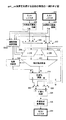
図20は、get_zz演算を実現する回路の構成の一例を示す図である。図20の演算器は、図2の演算回路119の一部分に相当する。図20において、図15と同一又は対応する構成要素は同一又は対応する番号で参照する。図20に示す演算器は、入力Xレジスタ221、入力Yレジスタ222、内部形式変換回路223及び224、指数仮数演算回路225A、セレクタ226及び227、シフタ228及び229、指数加算器230、及び絶対値加算器231を含む。演算器は更に、セレクタ232及び233、正規化回路234、外部形式変換回路235、出力Zレジスタ236、及び正規化回路270を含む。
FIG. 20 is a diagram illustrating an example of a configuration of a circuit that implements the get_zz operation. The arithmetic unit in FIG. 20 corresponds to a part of the arithmetic circuit 119 in FIG. In FIG. 20, the same or corresponding elements as those of FIG. 15 are referred to by the same or corresponding numerals. 20 includes an
内部形式変換回路223及び224により、入力を符号部、指数部、及び仮数部に分割し、入力の値表現を内部形式に変換する。入力Xの符号、指数、仮数をそれぞれ符号X、指数X、仮数Xとする。入力Yの符号、指数、仮数をそれぞれ符号Y、指数Y、仮数Yとする。
Internal
指数仮数演算回路225Aが、指数X及び指数Yと、仮数X及び仮数Yとを受け取る。指数仮数演算回路225Aは、指数Xと指数Yの大小比較をする。大小比較の結果に基づいて、指数仮数演算回路225Aは、指数の大きい側の仮数(第1の仮数)がシフタ228に入力され、且つ、指数の小さい側の仮数(第2の仮数)がシフタ229に入力されるように、セレクト信号を生成する。指数仮数演算回路225Aは、指数Xと指数Yとの差の絶対値と第1の仮数の先行ゼロ計数値とを比較し、指数Xと指数Yとの差の絶対値の方が大きい場合は、第1の仮数の先行ゼロ計数値をシフタ228の左シフト量として出力する。指数Xと指数Yとの差の絶対値の方が小さい場合は、指数仮数演算回路225Aは、指数Xと指数Yとの差の絶対値をシフタ228の左シフト量として出力する。
The exponent
指数仮数演算回路225Aは、指数Xと指数Yとの差の絶対値と第1の仮数の先行ゼロ計数値とを比較し指数Xと指数Yとの差の絶対値の方が大きい場合は、指数Xと指数Yとの差の絶対値から第1の仮数の先行ゼロ計数値を減算した値をシフタ229の右シフト量として出力する。第1の仮数の先行ゼロ計数値の方が小さい場合は、指数仮数演算回路225Aは、ゼロをシフタ229の右シフト量として出力する。指数仮数演算回路225Aは更に、指数の小さい側に上述の右シフト量を加算した値を指数として出力する。
The exponent
指数仮数演算回路225Aは更に、(指数X−仮数Xの先行ゼロ計数値)−(指数Y−仮数Yの先行ゼロ計数値)の絶対値が14以上であるか否かを判定する。この絶対値が14以上である場合、指数仮数演算回路225は、第2の仮数とそれに対応する指数がセレクタ232及び233により選択されるように、セレクト信号を生成する。これにより、上記(指数X−仮数Xの先行ゼロ計数値)−(指数Y−仮数Yの先行ゼロ計数値)の絶対値がフォーマットの桁数である14以上である場合には、第2の仮数が、シフタ228及び絶対値加算器231をバイパスして、正規化回路234に入力されることになる。
The exponent
シフタ228は、入力されたシフト量に基づき、入力された仮数を左シフトする。シフタ229は、入力されたシフト量に基づき、入力された仮数を右シフトする。各シフタのシフト結果は絶対値加算器231に入力される。
The
減算の場合は、片方の仮数が反転され、絶対値加算器231にキャリーが入力される。絶対値加算器231による加算の結果桁あふれが生じた場合は、1桁右にシフトした値が出力される。同時に、絶対値加算器231から指数加算器230にキャリーが送られ、指数に加算される。
In the case of subtraction, one mantissa is inverted and a carry is input to the
絶対値加算器231による加算の結果桁落ちが生じた場合は、1桁左にシフトした値が出力される。同時に、絶対値加算器231から指数加算器230に桁落ちを示す信号が送られ、指数から減算される。
If a digit loss occurs as a result of addition by the
正規化回路270が、加算結果と指数演算結果とを受け取り、正規化された指数部と仮数部とを出力する。
The
セレクタ232及び233は、指数仮数演算回路225によって生成されたセレクト信号に応じて、正規化された指数及び仮数、又は、第2の仮数及びそれに対応する指数を選択する。正規化回路234が、セレクタ232及び233により選択された指数及び仮数を受け取り、正規化演算結果を出力する。外部形式変換回路235は、正規化演算結果を外部形式に変換し、出力Zレジスタ236に出力する。
The
図21は、get_zz演算の具体例を示す図である。図21において、入力Xの指数をEx、入力Yの指数をEy、入力Xの先行ゼロ計数値をLx、出力Zの指数をEzとする。この例において実行する演算は、図21に示すget_zz演算280である。可能な限り高い演算精度を保持するとき、指数値の大きい側を左シフトして桁合わせを行う。但し、先行ゼロの桁数より多く左シフトすることは、上位桁が欠落してしまうため、桁合わせに必要な左シフト量Ex−Eyが先行ゼロの桁数を上回る場合は、指数値の小さい側を右シフトすることで、桁合わせを行う。このためにEx−Eyを計算し、Lxと比較する。図21に示す具体例ではLxのほうが大きい。即ち、左シフト量Ex−Eyが先行ゼロの数内に収まるので、入力Xの仮数281のみ左シフトされる。入力Yの仮数282は右シフトされない。左シフト量はEx−Eyであり、右シフト量は0である。
FIG. 21 is a diagram illustrating a specific example of the get_zz calculation. In FIG. 21, the exponent of the input X is Ex, the exponent of the input Y is Ey, the leading zero count value of the input X is Lx, and the exponent of the output Z is Ez. The calculation executed in this example is a
このようにして桁合わせされた数同士、即ち仮数281を左シフトして得られた仮数283と仮数282のままである仮数284とを加算する。更に、加算結果285を正規化し、先行ゼロ計数値が1以上の場合はその分だけ左シフトを行い、桁あふれがある場合には1桁分の右シフトを行う。但し、左シフトした結果指数が奇数になる場合は、左シフト量を1減らす。または右シフトした結果指数が奇数になる場合は、右シフト量を1増やす。指数は、左右シフト量に合わせて調整する。左シフトした場合は左シフト量を指数から減算し、右シフトした場合は右シフト量を指数に加算する。本具体例では1桁左シフトが必要だが、指数が0から1となり奇数になるので、左シフト量は1減らされて0となり、指数は0のままである。
The numbers aligned in this way, that is, the
次に、正規化結果の下位桁286を選択する。例えば入力フォーマットの仮数が14桁である場合は、最上位から14桁を上位桁、最上位から15桁目以降を下位桁とする。下位桁選択に伴い、指数は−14される。本具体例では、下位桁はゼロが選択される。
Next, the
更に、選択された下位桁287を正規化する。本具体例では対象データはゼロであるので、正規化前の仮数及び指数がそのまま正規化の結果として出力される。正規化された結果が、演算結果の仮数288及び対応する指数Ezを含む演算結果として出力される。
Further, the selected
図22は、get_zz演算の別の具体例を示す図である。この例において実行する演算は、図22に示す加算290である。可能な限り高い演算精度を保持するとき、指数値の大きい側を左シフトして桁合わせを行う。但し、先行ゼロの桁数より多く左シフトすることは、上位桁が欠落してしまうために不可能であるので、桁合わせに必要な左シフト量Ex−Eyが先行ゼロの桁数を上回る場合は、指数値の小さい側を右シフトすることで、桁合わせを行う。このためにEx−Eyを計算し、Lxと比較する。図22に示す具体例ではLxのほうが小さい。即ち、左シフト量Ex−Eyが先行ゼロの数内に収まらないので、入力Xの仮数291をLx分だけ左シフトし、左シフトしきれなかった分だけ入力Yの仮数292を右シフトする。即ち、左シフト量はLxであり、右シフト量は(Ex−Ey)−Lxである。
FIG. 22 is a diagram illustrating another specific example of the get_zz calculation. The calculation executed in this example is
このようにして桁合わせされた数同士、即ち仮数291を左シフトして得られた仮数293と仮数292を右シフトして得られた仮数294とを加算する。このとき、右シフトによって溢れた桁も保持する。
The numbers thus aligned, that is, the
更に、加算結果295を正規化し、先行ゼロ計数値が1以上の場合はその分だけ左シフトを行い、桁あふれがある場合には1桁分の右シフトを行う。但し、左シフトした結果指数が奇数になる場合は、左シフト量を1減らす。または右シフトした結果指数が奇数になる場合は、右シフト量を1増やす。指数は、左右シフト量に合わせて調整する。左シフトした場合は左シフト量を指数から減算し、右シフトした場合は右シフト量を指数に加算する。本具体例では1桁右シフトが必要だが、指数が2から3となり奇数になるので、右シフト量は1増やされて4となり、指数は2から4となる。
Further, the
次に、正規化結果の下位桁296を選択する。例えば入力フォーマットの仮数が14桁である場合は、最上位から14桁を上位桁、最上位から15桁目以降を下位桁とする。下位桁選択に伴い、指数は−14される。
Next, the
更に、選択された下位桁297を正規化する。本具体例では、仮数は2桁左にシフトされ、指数は−10から2が減算されて−12となる。正規化された結果が、演算結果の仮数298及び対応する指数Ezを含む演算結果として出力される。
Further, the selected
図23は、get_zz演算の更に別の具体例を示す図である。この例において実行する演算は、図23に示すget_zz演算300である。可能な限り高い演算精度を保持するとき、指数値の大きい側を左シフトして桁合わせを行う。但し、先行ゼロの桁数より多く左シフトすることは、上位桁が欠落してしまうため、桁合わせに必要な左シフト量Ex−Eyが先行ゼロの桁数を上回る場合は、指数値の小さい側を右シフトすることで、桁合わせを行う。但し、桁合わせした結果、2つの入力の間に14桁以上の差がある場合、即ち、重なりが全くない場合には、実際に演算処理を実行しなくとも演算結果を求めることが可能である。get_zzは演算結果の下位側を求める演算であり、2入力の重なりがない場合には値の小さい側がそのまま下位側となるからである。
FIG. 23 is a diagram illustrating still another specific example of the get_zz calculation. The calculation executed in this example is a
この条件を満たすか否かを確認するため、(Ex−Lx)−(Ey−Ly)を計算し、計算結果が14以上の場合には上記の場合に該当すると判定する。ここで値14は、使用フォーマットにおける仮数の桁数である。この具体例では上記の場合に該当し、仮数301と仮数302との間に重なりが存在しない。この場合、仮数302がそのままバイパスされて加算結果として取り扱われる。
In order to check whether or not this condition is satisfied, (Ex−Lx) − (Ey−Ly) is calculated, and when the calculation result is 14 or more, it is determined that the above case is satisfied. Here, the
更にバイパスされた結果303を正規化し、先行ゼロ計数値が1以上の場合はその分だけ左シフトを行い、桁あふれがある場合には1桁分の右シフトを行う。但し、左シフトした結果指数が奇数になる場合は、左シフト量を1減らす。または右シフトした結果指数が奇数になる場合は、右シフト量を1増やす。指数は、左右シフト量に合わせて調整する。左シフトした場合は左シフト量を指数から減算し、右シフトした場合は右シフト量を指数に加算する。本具体例では1桁左シフトが必要だが、指数が0から−1となり奇数になるので、左シフト量は1減らされて0となり、指数は0のままとなる。このようにして得られた正規化の結果が、そのまま演算結果の仮数304及び対応する指数Ezを含む演算結果として出力される。
Further, the bypassed
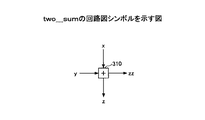
図24は、two_sumの回路図シンボルを示す図である。上述したtwo_sumは、triple−oraclenum64計算において頻繁に用いられる演算である。このtwo_sum演算、即ちxとyとの正確な和を表現するzとzzとを求める演算を、図24に示すような演算子310で表わすものとする。
FIG. 24 is a diagram illustrating a circuit diagram symbol of two_sum. The above two_sum is an operation frequently used in the triple-oraclenum64 calculation. This two_sum operation, that is, an operation for obtaining z and zz that expresses an accurate sum of x and y is represented by an
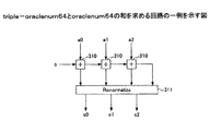
図25は、triple−oraclenum64とoraclenum64の和を求める回路の一例を示す図である。図25に示す回路は、3つのtwo_sum演算子310と再正規化部311とを含む。入力bは1つのoraclenum64の数であり、入力a0,a1,a2はtriple−oraclenum64である。また出力s0,s1,s2もまたtriple−oraclenum64である。図25に示すような回路構成により、triple−oraclenum64とoraclenum64の和を求めることができる。なお再正規化部311が実行する演算については、後述する。
FIG. 25 is a diagram illustrating an example of a circuit for calculating the sum of triple-oraclenum64 and oraclenum64. The circuit shown in FIG. 25 includes three
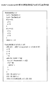
図26は、triple−oraclenum64同士の和を求めるアルゴリズムを示す図である。前述のtwo−sumを用いて、triple−oraclenum64同士の和を求めることができる。図26に示すTriple_Addは、第1のtriple−oraclenum64であるa0,a1,a2と第2のtriple−oraclenum64であるb0,b1,b2との和を求める。この演算は、非特許文献2のA.2節に開示されているものと同様である。また非特許文献3に開示されるalgorithm13,14とも同様である。残りの四則演算についても、非特許文献1乃至3に開示の方法を用いて実現可能である。
FIG. 26 is a diagram showing an algorithm for calculating the sum of triple-oraclenum 64. The above-mentioned two-sum can be used to obtain the sum of triple-oraclenum64. Triple_Add shown in FIG. 26 calculates the sum of a0, a1, and a2 that are the first triple-oraclenum64 and b0, b1, and b2 that are the second triple-oraclenum64. This calculation is described in A. This is the same as that disclosed in
以下に、計算結果の再正規化について述べる。再正規化については、非特許文献2のp.116に述べられており、非特許文献3でもそれを参照している。ここでは、非特許文献2に記載される再正規化をPriestの再正規化と呼ぶ。再正規化前の演算結果(X0,X1,X2,X3)は、概ね絶対値の大きい順に並んでいるが、一般に、一部の桁にオーバーラップがある。また、X0がX0+X1+X2+X3の最重要(most significant)な部分を固定精度で表現した結果になっていない。
The renormalization of calculation results is described below. Regarding renormalization, p. 116, which is also referred to in
計算結果(X0,X1,X2,X3)をPriestの方法で再正規化した結果を(a0,a1,a2)とすると、a0+a1+a2は、X0+X1+X2+X3とtripleの範囲で等しく、且つ、以下を満たす。 Assuming that the calculation result (X0, X1, X2, X3) is renormalized by the Priest method as (a0, a1, a2), a0 + a1 + a2 is equal to X0 + X1 + X2 + X3 in the range of triple and satisfies the following.
|a0| ≧|a1| ≧ |a2|
E(i+1) ≦ Ei - 14
ここで、Eiは基数を10とした場合の要素aiの指数である。oraclenum64の精度は10進で14桁なので、上記の第2の条件は、要素がオーバーラップしていないことを表わす。
| a0 | ≧ | a1 | ≧ | a2 |
E (i + 1) ≤ Ei-14
Here, Ei is an index of the element ai when the radix is 10. Since the accuracy of oraclenum64 is 14 digits in decimal, the above second condition indicates that the elements do not overlap.
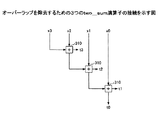
Priestの再正規化にも、前述のtwo_sumが用いられる。まず、オーバーラップを除去するために、図27のように接続された3つのtwo_sum演算子310を用いる。これにより得られる(t0,t1,t2,t3)は、オーバーラップしておらず、且つ、0でない要素については絶対値の大きいものから順に並んでいる。これらをt0から順に蓄積していったものを(a0,a1,a2)とすればよい。この蓄積を行なう演算accumulateにもtwo_sumが用いられる。
The above two_sum is also used for re-normalization of Priest. First, in order to remove the overlap, three
一般に再正規化前の演算結果(X0,X1,X2,X3)の符号は揃ってなく、前述のようにtwo_sumを繰り返した結果である(a0,a1,a2)の符号も揃っていない。そこでPriestの再正規化を行った固定精度浮動小数点数の組に含まれる数の符号が全て同符号な場合を、符号の揃ったPriestの再正規化と呼ぶ。 In general, the codes of the calculation results (X0, X1, X2, X3) before renormalization are not aligned, and the codes of (a0, a1, a2), which are the results of repeating two_sum as described above, are not aligned. Therefore, when all the codes included in the set of fixed-precision floating-point numbers that have undergone Priest renormalization have the same sign, they are referred to as Priest renormalization with uniform codes.
本願では、Priestの再正規化よりも条件の厳しい「強い正規化」を用いる。強い正規化された組(b0,b1,b2)は、次の条件を満たす。なお強い正規化により、b1=0且つb2≠0となる場合が生じるため、|b0|>=|b1|>=|b2|の条件は一般に成り立たない。 In the present application, “strong normalization”, which is more severe than the Priest renormalization, is used. The strongly normalized set (b0, b1, b2) satisfies the following condition. It should be noted that the condition of | b0 |> = | b1 |> = | b2 | generally does not hold because strong normalization may result in b1 = 0 and b2 ≠ 0.
E(i+1) = Ei - 14
b0,b1,b2:全て同符号
このような強い正規化により、各要素の指数の差と固定小数点数の精度(桁数)とが一致する。従って、強い正規化された組を元のOracle−number表現に戻すことは容易である。
E (i + 1) = Ei-14
b0, b1, b2: All have the same sign By such a strong normalization, the difference in exponents of each element matches the precision (number of digits) of the fixed-point number. Therefore, it is easy to return a strongly normalized tuple to the original Oracle-number representation.
まず図27で示されるオーバーラップが無く0以外の数は絶対値の大きいものから順に並んでいる数の組(t0,t1,t2,・・・)から、符号の揃ったPriestの再正規化された数の組(a0,a1,a2,・・・)を得るための処理を示す。ここでfl_truncate(X+Y)は、固定精度浮動小数点数XとYとの和を有効桁で切り捨てる演算を表し、two_sum(X,Y)は前述の通り有効桁に重なりの無い2数を求める演算とする。但しここではtwo_sum内での演算は全て四捨五入で丸め処理されるものとする。 First, the non-overlapping numbers shown in FIG. 27 are re-normalized for the Priest with the same code from a set of numbers (t0, t1, t2,...) Arranged in descending order of the absolute value. A process for obtaining a set of the numbers (a0, a1, a2,...) Is shown. Here, fl_truncate (X + Y) represents an operation of truncating the sum of fixed-precision floating-point numbers X and Y with significant digits, and two_sum (X, Y) is an operation for obtaining two numbers that do not overlap with significant digits as described above. To do. However, here, all calculations in two_sum are rounded off by rounding off.
a0 = fl_truncate(t0+t1)
(z0,zz0) = two_sum(t0,t1)
zz0=0の場合、以下の様にzz0≠0となるまでt2,t3,・・・を順次accumulateしていく。
a0 = fl_truncate (t0 + t1)
(z0, zz0) = two_sum (t0, t1)
When zz0 = 0, t2, t3,... are successively accumulated until zz0 ≠ 0 as follows.
a0 = fl_truncate(a0+t2)
(z0,zz0) = two_sum(a0,t2)
入力された数の組(t0,t1,t2,・・・)を全てaccumulateされてもzz0=0な場合はそこで処理を終了する。以下zz0≠0となった後の処理を示す。
a0 = fl_truncate (a0 + t2)
(z0, zz0) = two_sum (a0, t2)
Even if all the pairs (t0, t1, t2,...) Of the input numbers are accumulated, if zz0 = 0, the process is terminated. The processing after zz0 ≠ 0 is shown below.
w0 = fl_truncate(z0 - a0)
ここで、two_sumの性質より、
t0+t1+...+ti = z0+zz0 = a0+w0+zz0
となる。但しt0,t1,・・・,tiはzz0≠0となるまでaccumulateされた数である。この時、以下の通りa0と(w0+zz0)は同符号であり、且つ、a0と(w0+zz0)に有効桁の重なりは無いと言える。
w0 = fl_truncate (z0-a0)
Here, from the nature of two_sum,
t0 + t1 + ... + ti = z0 + zz0 = a0 + w0 + zz0
It becomes. However, t0, t1,..., Ti are accumulated numbers until
(i)w0=0の場合:zz0はfl_truncate(t0+t1+...+ti)によって切り捨てられた数に等しいため、a0と(w0+zz0)は同符号であり、且つ、a0と(w0+zz0)に有効桁の重なりは無い。 (I) When w0 = 0: Since zz0 is equal to the number truncated by fl_truncate (t0 + t1 + ... + ti), a0 and (w0 + zz0) have the same sign, and a0 and (w0 + zz0) There is no overlap of significant digits.
(ii)w0≠0の場合:w0はa0と同符号でa0の有効桁最下位にのみ1が立つ数であり、zz0の絶対値はw0の絶対値よりも小さくzz0とw0は異符号なため、a0と(w0+zz0)は同符号であり、且つ、a0と(w0+zz0)に有効桁の重なりは無い。 (ii) When w0 ≠ 0: w0 is a number that has the same sign as a0, and 1 stands only at the lowest significant digit of a0. The absolute value of zz0 is smaller than the absolute value of w0, and zz0 and w0 have different signs. Therefore, a0 and (w0 + zz0) have the same sign, and a0 and (w0 + zz0) have no significant digit overlap.
次に、(w0,zz0,ti+1,...)に対して同様の処理を繰り返すことで、a1,a2,・・・を順次求めることができる。この際、上記(i),(ii)によりa1,a2,・・・は全て同符合となる。 Next, by repeating the same processing for (w0, zz0, ti + 1,...), A1, a2,. At this time, a1, a2,... All have the same sign according to the above (i) and (ii).
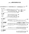
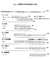
図28は、符号の揃ったPriestの再正規化の例を示す図である。この例においては、簡単のために固定精度浮動小数点数は10進4桁とし、two_sumでの丸め処理方法は四捨五入であるとする。図28において、(t0,t1,t2,t3)はオーバーラップしておらず、且つ、0でない要素については絶対値の大きいものから順に並んでいる。これらをt0から順に蓄積していくことで、符号の揃ったPriestの再正規化された数の組a0,a1,a2,a3が得られている。 FIG. 28 is a diagram illustrating an example of Priest re-normalization with the same code. In this example, for the sake of simplicity, the fixed-precision floating-point number is assumed to be four decimal digits, and the rounding method in two_sum is rounded off. In FIG. 28, (t0, t1, t2, t3) do not overlap, and elements that are not 0 are arranged in descending order of absolute value. By accumulating these in order from t0, a set of re-normalized priests a0, a1, a2, and a3 having the same code is obtained.
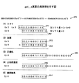
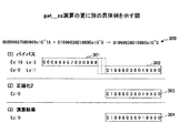
図29は、符号の揃ったPriestの再正規化された数の組から強い正規化された数の組を得る計算の一例を示す図である。強い正規化のためには、符号の揃ったPriestの再正規化された数の組から第2要素以降を適切に量子化してやればよい。図29に示す例では、簡単のために固定精度浮動小数点数は10進4桁としてある。図29に示されるように、符号の揃ったPriestの再正規化された数の組(a0,a1,a2)から強い正規化が行われた数の組(b0,b1,b2)が求められている。 FIG. 29 is a diagram illustrating an example of calculation for obtaining a strongly normalized number set from the re-normalized number set of Pris with the same code. For strong normalization, the second and subsequent elements may be appropriately quantized from the re-normalized number of Priests with uniform codes. In the example shown in FIG. 29, the fixed-precision floating-point number is assumed to be four decimal digits for simplicity. As shown in FIG. 29, a strongly-normalized number set (b0, b1, b2) is obtained from the re-normalized number set (a0, a1, a2) of the Priest with the same code. ing.
図30は、量子化のためのscale_next(X,Y)演算を実現する回路構成の一例を示す図である。図30に示す回路は、指数補正値レジスタ320、入力Xレジスタ321、入力Yレジスタ322、内部形式変換回路323及び324、指数加算器325、シフト量演算回路326、右シフタ327、外部形式変換回路328、及び出力Zレジスタ329を含む。この回路の入力データは以下の条件を満たしていることを前提としている。
FIG. 30 is a diagram illustrating an example of a circuit configuration for realizing a scale_next (X, Y) operation for quantization. 30 includes an exponent
指数Y ≧ 指数X + t
ここでtはoraclenum64の桁数である。本実施例では、tは例えば14である。
Exponent Y ≥ Exponent X + t
Here, t is the number of digits of oraclenum64. In this embodiment, t is 14, for example.
内部形式変換回路323及び324により、入力を指数部及び仮数部に分割し、入力の値表現を内部形式に変換する。入力Xの指数及び仮数をそれぞれ指数X及び仮数Xとする。入力Yの指数を指数Yとする。指数補正値レジスタ320には、予め決められた固定値tが格納される。レジスタ格納値として設定するのではなく、ハード的に固定値を設定してもよい。
Internal
シフト量演算回路326が指数Xと指数Yと固定値tを受け取る。シフト量演算回路326は、指数Y−指数X−tの演算結果をシフト量として出力する。右シフタ327は、このシフト量と仮数Xとを受け取り、仮数Xを当該シフト量だけ右シフトした結果を出力する。シフトアウトした桁は捨てられる。
The shift
指数加算器325は、指数Yと固定値tとを受け取り、指数Y−tの演算結果を出力する。外部形式変換回路328は、指数加算器325からの指数と右シフタ327からの仮数を外部形式に変換し、出力Zレジスタ329に出力する。
The
図31は、仮数部を内部形式に変換せずにscale_next演算を行う回路の構成の一例を示す図である。図31において、図30と同一の構成要素は同一の番号で参照し、その説明は適宜省略する。図31では、内部形式変換回路323の代りに内部形式変換回路323Aが設けられ、外部形式変換回路328の代りに外部形式変換回路328Aが設けられている。入力データがoraclenum64形式の場合、右シフタはシフト量2につき8ビットシフトする。
FIG. 31 is a diagram illustrating an example of a configuration of a circuit that performs a scale_next operation without converting the mantissa part into an internal format. 31, the same components as those of FIG. 30 are referred to by the same numerals, and a description thereof will be omitted as appropriate. In FIG. 31, an internal
内部形式変換回路323A及び324により、入力を指数部及び仮数部に分割し、入力の値表現を内部形式に変換する。入力Xの指数を指数Xとする。入力Yの指数を指数Yとする。指数補正値レジスタ320には、予め決められた固定値tが格納される。レジスタ格納値として設定するのではなく、ハード的に固定値を設定してもよい。
The internal
シフト量演算回路326が指数Xと指数Yと固定値tを受け取る。シフト量演算回路326は、指数Y−指数X−tの演算結果をシフト量として出力する。右シフタ327は、このシフト量と仮数Xとを受け取り、仮数Xを当該シフト量だけ右シフトした結果を出力する。シフトアウトした桁は捨てられる。
The shift
指数加算器325は、指数Yと固定値tとを受け取り、指数Y−tの演算結果を出力する。外部形式変換回路328Aは、指数加算器325からの指数を外部形式に変換し、出力Zレジスタ329に出力する。また右シフタ327の出力する右シフト後の仮数は、そのまま出力Zレジスタ329に出力される。
The
以下に、triple−oraclenum64形式に対する丸め処理を考える。ここでは、丸め処理対象であるtriple−oraclenum64形式の数の組(a0,a1,a2)は再正規化されていることを前提とする。なおこの前提条件は、Priestの再正規化及び強い正規化の何れであってもよい。 In the following, a rounding process for the triple-oraclenum64 format will be considered. Here, it is assumed that a triple-oracle64 format number set (a0, a1, a2) to be rounded is renormalized. This precondition may be either Priest's renormalization or strong normalization.
図32は、Oracle−Database(商標)におけるNUMBER型の3種類の精度指定方法を示す表である。ここで、丸め方向は常に四捨五入である。例えば、計算結果が 1234.56だった場合に、NUMBER(4)、NUMBER(4,−2)、NUMBER(4,1)のそれぞれの指定に対する丸め結果は、以下の通りとなる。 FIG. 32 is a table showing three types of accuracy designation methods of NUMBER type in Oracle-Database (trademark). Here, the rounding direction is always rounded off. For example, when the calculation result is 1234.56, the rounding results for the designations of NUMBER (4), NUMBER (4, -2), and NUMBER (4, 1) are as follows.
NUMBER(4)→1234
NUMBER(4,−2)→1200
NUMBER(4,1)→エラー
最後の例でエラーとなるのは、計算結果である1234.56を小数点1位まで表わすように丸めた結果である1234.6が、4桁の精度内に収まらないためである。
NUMBER (4) → 1234
NUMBER (4, -2) → 1200
NUMBER (4,1) → error In the last example, an error occurs. 1234.6, which is the result of rounding the calculation result 1234.56 to the first decimal place, falls within the precision of 4 digits. This is because there is not.
triple−oraclenum64形式においても、このような丸め処理を、エラー判定も含めて効率良く実現する必要がある。ここで用いることのできる演算器は、8バイト幅のオペランドを2つの入力として、1つの8バイト幅の数を出力する演算器である。丸め処理においても、このような演算器を前提とする。 Even in the triple-oraclenum64 format, it is necessary to efficiently implement such rounding processing including error determination. An arithmetic unit that can be used here is an arithmetic unit that outputs an 8-byte-wide number with two 8-byte-wide operands as two inputs. Such an arithmetic unit is also assumed in the rounding process.
そこで、triple−oraclenum64で表現された数の丸め処理を、以下の3ステップで実現することにする。 Therefore, the rounding process of the number expressed by triple-oraclenum64 is realized by the following three steps.
1)四捨五入が発生する桁位置のみ5があるような数を生成する。 1) Generate a number with 5 only at the digit position where rounding occurs.
2)triple−oraclenum64形式の数に、上で生成した数を加える。 2) Add the number generated above to the number in triple-oraclenum64 format.
3)適切な桁位置で切捨てを行う。
まず、第1ステップのアルゴリズムについて述べる。以降、丸め対象数のtriple−oraclenum64表現を(a0,a1,a2)とする。また、この組の最重要要素a0の値は、
a0 = M * 100^e
で表わされるとする。また、上式のeを求めるための演算をe(a0)と表すことにする。
3) Truncate at an appropriate digit position.
First, the first step algorithm will be described. Hereinafter, the triple-oraclenum64 expression of the rounding target number is (a0, a1, a2). The value of the most important element a0 of this set is
a0 = M * 100 ^ e
It is assumed that In addition, the calculation for obtaining e in the above equation is represented as e (a0).
第1ステップは、精度指定方法により、生成アルゴリズムが異なる。精度指定がない場合(引数なしのNUMBER指定の場合)には、仮数部が20バイト以下となるように丸めが行われる必要がある。 In the first step, the generation algorithm differs depending on the accuracy designation method. When the precision is not specified (when the NUMBER is specified without an argument), it is necessary to perform rounding so that the mantissa part is 20 bytes or less.
精度指定時のアルゴリズムを記述するには、a0を10進表記で表した方が都合がよい。そこで、
a0 = M' * 10^e'
の形で表す。また、仮数部が10>|M'|>=0を満たすように正規化されているものとする。また、前と同様に、e'を求めるための演算をe'(a0)と表す。
In order to describe an algorithm for specifying accuracy, it is more convenient to express a0 in decimal notation. there,
a0 = M '* 10 ^ e'
In the form of It is assumed that the mantissa part is normalized so as to satisfy 10> | M ′ |> = 0. Further, as before, the calculation for obtaining e ′ is represented as e ′ (a0).
図33は、四捨五入が発生する桁位置のみ5があるような数を生成するアルゴリズムの例を示す図である。図33(a)及び(b)には、10進桁数による精度指定の場合のアルゴリズムが示される。これら2つのアルゴリズムは、いずれも2入力1出力型の演算器として実現可能である。図33(c)には、スケール(小数点からの相対位置)指定の場合のアルゴリズムが示される。小数点からの相対位置を指定するので、a0に依存しない計算となる。この図33(c)に示すアルゴリズムは、図示した通りの数式をそのままプログラム化してもよいが、nの各値に対応するテーブルを用意しておいて、nをキーにテーブルを引くようなプログラムを用意してもよい。 FIG. 33 is a diagram illustrating an example of an algorithm for generating a number in which there is 5 only at the digit position where rounding occurs. FIGS. 33 (a) and 33 (b) show an algorithm in the case of designating precision by decimal digits. Both of these two algorithms can be realized as a 2-input 1-output type arithmetic unit. FIG. 33C shows an algorithm in the case of specifying the scale (relative position from the decimal point). Since the relative position from the decimal point is designated, the calculation does not depend on a0. In the algorithm shown in FIG. 33 (c), a mathematical expression as illustrated may be programmed as it is, but a program that prepares a table corresponding to each value of n and draws the table using n as a key. May be prepared.
スケール指定があった場合に、丸めた結果が指定精度に収まるか否かは、以下のように判定できる。NUMBER(p,s)が指定された場合、まず、上述の精度指定の場合のアルゴリズムとスケール指定のアルゴリズムとを両方用いて、p_d及びp_sの2つの値を計算する。 When the scale is specified, whether or not the rounded result falls within the specified accuracy can be determined as follows. When NUMBER (p, s) is designated, first, two values of p_d and p_s are calculated using both the above-described algorithm for precision designation and the algorithm for scale designation.
p_d = get_comma5(a0, digits=p)
p_s = get_comma5(scale=s)
このとき、|p_d|>|p_s|となった場合、すなわちp_dの絶対値がp_sの絶対値よりも大きい場合には、スケール指定で丸められた結果を表現するためには、精度が不足していることがわかる。
p_d = get_comma5 (a0, digits = p)
p_s = get_comma5 (scale = s)
At this time, if | p_d |> | p_s |, that is, if the absolute value of p_d is larger than the absolute value of p_s, the accuracy is insufficient to express the rounded result by the scale designation. You can see that
次に第2ステップでは、第1ステップで生成した数を、triple−oraclenum64で表現された数に加える。この加算には、図25に示したアルゴリズムが利用できる。 Next, in the second step, the number generated in the first step is added to the number expressed by triple-oraclenum64. For this addition, the algorithm shown in FIG. 25 can be used.
第3ステップでは、適切な位置で切り捨てを行う。ここでも、第1ステップで生成した数p(精度指定の方式に応じたp_dまたはp_sの何れかの値)を利用することができる。この数pは、四捨五入のために加算される数であり、丸めが発生する桁位置に関する情報を完全に含んでいる。そのため、triple−oraclenum64の各要素とpとの2つのオペランドを入力として、各要素を適切にtruncateする演算を定義することができる。 In the third step, truncation is performed at an appropriate position. Again, the number p generated in the first step (either p_d or p_s depending on the accuracy designation method) can be used. This number p is a number added for rounding off, and completely includes information on the digit position where rounding occurs. For this reason, it is possible to define an operation for appropriately truncating each element by using two operands of each element of triple-oraclenum64 and p.
第2ステップの計算結果を(b0,b1,b2)とすると、丸めの第3段階の結果(c0,c1,c2)は、
c0 = truncate(b0, p)
c1 = truncate(b1, p)
c2 = truncate(b2, p)
となる。
If the calculation result of the second step is (b0, b1, b2), the result of the third rounding step (c0, c1, c2) is
c0 = truncate (b0, p)
c1 = truncate (b1, p)
c2 = truncate (b2, p)
It becomes.
図34は、get_comma5(precision)を実現する回路構成の一例を示す図である。図34に示す回路は、精度pレジスタ330、入力Xレジスタ331、内部形式変換回路332、先行ゼロ計数回路333、指数加算器334、レジスタ335及び336、セレクタ337、外部形式変換回路338、及び出力Zレジスタ339を含む。
FIG. 34 is a diagram illustrating an example of a circuit configuration that implements get_comma5 (precise). 34 includes an
内部形式変換回路332により、入力を指数部及び仮数部に分割し、入力の値表現を内部形式に変換する。入力Xの指数と仮数をそれぞれ指数X、仮数Xとする。先行ゼロ計数回路333は、仮数Xを受け取り、仮数X中の先行ゼロの数を計数する。指数加算器334は、指数X+1−精度p−仮数Xの先行ゼロ計数値を計算する。セレクタ337は、指数加算器334の出力が奇数の場合にはレジスタ336の5000−00を選択し、指数加算器334の出力が偶数の場合にはレジスタ335の0500−00を選択する。
The internal
指数加算器334から外部形式変換回路338へ供給される指数は、指数加算器334の出力が奇数の場合は当該指数の最下位ビットをゼロとし、指数加算器334の出力が偶数の場合はそのままとする。外部形式変換回路338は、内部形式変換回路332からの符号、指数加算器334からの指数、及びセレクタ337からの仮数を外部形式の数に変換して、変換結果を出力Zレジスタ339に出力する。
The exponent supplied from the
図35は、truncate演算を実現する回路構成の一例を示す図である。図35の回路は、入力Xレジスタ340、comma5レジスタ341、内部形式変換回路342及び343、先行ゼロ計数回路344、マスク値生成回路345、マスク回路346、外部形式変換回路347、及び出力Zレジスタ348を含む。
FIG. 35 is a diagram illustrating an example of a circuit configuration that implements a truncate operation. 35 includes an
内部形式変換回路342及び343により、入力を符号、指数部、及び仮数部に分割し、入力の値表現を内部形式に変換する。入力Xの符号、指数、及び仮数をそれぞれ符号X、指数X、及び仮数Xとする。入力comma5の指数と仮数をそれぞれ指数c及び仮数cとする。
Internal
先行ゼロ計数回路344は、仮数cを受け取り、仮数c中の先行ゼロの数を計数する。マスク値生成回路345は、指数X、指数c、及び仮数cの先行ゼロ計数値を入力として受け取り、これらの入力に応じてマスクデータを生成する。マスク回路346は、仮数Xをマスクデータに応じてマスクし、マスク後の値を仮数として出力する。外部形式変換回路347は、内部形式変換回路342からの符号X及び指数X並びにマスク回路346からの仮数を外部形式の数に変換して、変換結果を出力Zレジスタ348に出力する。
The leading zero
図36は、マスク値生成回路の構成の一例を示す図である。図36に示すマスク値生成回路345は、マスク桁演算回路350、デコーダ351、及びセレクタ352−1乃至352−14を含む。マスク桁演算回路350は、指数X、指数c、及び先行ゼロ計数値Lcを受け取り、マスク桁を演算する。マスク桁は、使用フォーマットの仮数の桁数を14とすると、14+(指数c−Lc)−指数Xで求められる。この値は、マスクデータの最下位桁から何桁目までがゼロに設定されるかを示す。このように計算されたマスク桁演算結果に基づいて、デコーダ351が、桁ごとのセレクト信号を生成する。デコーダ351が生成したセレクト信号は、14桁にそれぞれ対応するセレクタ352−1乃至352−14に供給される。マスク桁演算結果がnの場合、下位からn桁は0000側を選択するようにセレクト信号が生成される。マスク桁演算結果が0の場合は、全ての桁が1111側を選択するようにセレクト信号が生成される。このセレクト信号に応じて、セレクタ352−1乃至352−14が、1111又は0000の何れかのビット列を選択し、選択したビット列をマスクデータとして出力する。
FIG. 36 is a diagram illustrating an example of the configuration of the mask value generation circuit. The mask
図37は、p_d及びp_sの絶対値大小比較エラー判定回路の構成の一例を示す図である。この回路は、p_sレジスタ360、p_dレジスタ361、内部形式変換回路362及び363、指数仮数演算回路364、セレクタ365及び366、シフタ367及び368、符号演算器369、加算器370、コンプリメンタ372、コンプリメンタ373、及びエラーフラグレジスタ371を含む。
FIG. 37 is a diagram illustrating an example of a configuration of an absolute value magnitude comparison error determination circuit for p_d and p_s. This circuit includes a
内部形式変換回路362及び363により、入力を指数部、及び仮数部に分割し、入力の値表現を内部形式に変換する。入力p_sの指数、仮数をそれぞれ指数X、仮数Xとする。入力p_dの指数、仮数をそれぞれ指数Y、仮数Yとする。
The internal
指数仮数演算回路364が、指数X及び指数Yと、仮数X及び仮数Yとを受け取る。指数仮数演算回路364は、指数Xと指数Yの大小比較をする。大小比較の結果に基づいて、指数仮数演算回路364は、指数の大きい側の仮数(第1の仮数)がシフタ367に入力され、且つ、指数の小さい側の仮数(第2の仮数)がシフタ368に入力されるように、セレクト信号を生成する。指数仮数演算回路364は、指数Xと指数Yとの差の絶対値と第1の仮数の先行ゼロ計数値とを比較し、前者の方が大きい場合は、後者をシフタ367の左シフト量として出力する。前者の方が小さい場合は、指数仮数演算回路364は、前者をシフタ367の左シフト量として出力する。
An exponent
指数仮数演算回路364は、指数Xと指数Yとの差の絶対値と第1の仮数の先行ゼロ計数値とを比較し、前者の方が大きい場合は、前者から後者を減算した値をシフタ368の右シフト量として出力する。前者の方が小さい場合は、指数仮数演算回路364は、ゼロをシフタ368の右シフト量として出力する。
The exponent
シフタ367は、入力されたシフト量に基づき、入力された仮数を左シフトする。シフタ368は、入力されたシフト量に基づき、入力された仮数を右シフトする。各シフタのシフト結果はコンプリメンタ372、コンプリメンタ373に入力される。
The
コンプリメンタ372は入力された前述のセレクト信号が反転された信号により入力された左シフトの出力をコンプリメントするEOR回路(排他的論理和回路)である。コンプリメンタ373は入力された前述のセレクト信号により入力された右シフトの出力をコンプリメントするEOR回路(排他的論理和回路)である。各コンプリメンタの結果は加算器370に入力される。
The
加算器370にキャリーが入力される。加算器370による加算の結果桁あふれが生じた場合は、符号演算器369にキャリーアウトが供給される。
Carry is input to adder 370. When overflow occurs as a result of the addition by the
符号演算器369は、加算器370からキャリーアウトを受け取る。符号演算器369は、キャリーアウトの反転値が1であるとき、エラーフラグを1にする。それ以外の場合において、エラーフラグは0である。符号演算器369が生成するエラーフラグは、エラーフラグレジスタ371に格納される。
The
図38は、上記の符号演算器の回路構成の一例を示す図である。図38(a)に示す符号演算器は、インバータ380を含む。この回路により、キャリーアウトの反転値が1のとき、エラーフラグが1になる。図38(b)に示す表は、p_dとp_sの絶対値大小比較エラー判定回路に入力されたp_dとp_sの絶対値の大小関係と、その場合に出力される各信号の対応表である。ここで|p_d|はp_dの絶対値である。p_sについても同様である。
FIG. 38 is a diagram illustrating an example of a circuit configuration of the sign arithmetic unit. The sign calculator shown in FIG. 38A includes an
図39は、Oracle−numberの長さを求める演算の一例を示す図である。前述の演算の結果として得られたtriple−oracelnum64形式の数を、1つのOracle−numberとしてメモリに書き込む際には、このOracle−numberの長さを求める必要がある。Oracle−numberの長さを求めるには、図39に示されるようにすればよい。但し、length(aX)は、oraclenum64形式での有効桁数を求める演算とする。a2が0であればOracle−numberの長さは短くなるし、更にa1が0であればOracle−numberの長さは更に短くなる。 FIG. 39 is a diagram illustrating an example of an operation for obtaining the length of the Oracle-number. When writing the number of triple-oraclenum64 format obtained as a result of the above-mentioned operation into the memory as one Oracle-number, it is necessary to obtain the length of this Oracle-number. What is necessary is just to make it show in FIG. 39 in order to obtain | require the length of Oracle-number. However, length (aX) is an operation for obtaining the number of significant digits in the oraclenum64 format. If a2 is 0, the length of the Oracle-number is shortened, and if a1 is 0, the length of the Oracle-number is further shortened.
強い再正規化を施したtriple−oracelnum64形式において、a0、a1、a2は、1つのOracle−numberの仮数部を7バイト、7バイト、6バイトの3つの部分に分割した各部を表現している。従って、基本的には、a0、a1、a2の仮数部を連結するだけで、Oracle−number表現が得られる。但し、a0、a1の長さが短い場合には、後続ゼロを拡張してからメモリに格納する必要がある。 In triple-oraclenum64 format with strong renormalization, a0, a1, and a2 represent each part obtained by dividing the mantissa part of one Oracle-number into three parts of 7 bytes, 7 bytes, and 6 bytes. . Therefore, basically, an Oracle-number expression can be obtained by simply concatenating the mantissa parts of a0, a1, and a2. However, if the lengths of a0 and a1 are short, it is necessary to expand trailing zeros and store them in the memory.
図40は、expand演算を実現する回路の構成の一例を示す図である。図40の回路は、入力Xレジスタ390、内部形式変換回路391、後続ゼロ計数回路392、桁セレクト演算回路393、及び出力Zレジスタ394を含む。
FIG. 40 is a diagram illustrating an example of the configuration of a circuit that implements an expand operation. The circuit of FIG. 40 includes an
内部形式変換回路391は、入力Xレジスタ390の格納値の仮数部を受け取り、内部形式の仮数部を出力する。後続ゼロ計数回路392は、内部形式の仮数部を受け取り、受け取った仮数部から後続ゼロの数を求め、後続ゼロの計数結果を基にした桁セレクトデータを出力する。桁セレクト演算回路393は、入力Xレジスタ390から格納値の符号部と仮数部とを受け取り、更に後続ゼロ計数回路392から桁セレクトデータを受け取る。符号と桁セレクトデータとに基づいて、桁セレクト演算回路393は、受け取った仮数又はoraclenum64のゼロ(0x01または0x65)の何れかを桁毎に選択して出力する。後続ゼロ計数回路392において後続ゼロの部分であると判断された桁においては、ゼロが選択されて出力される。出力されたデータは出力Zレジスタ394に格納される。
The internal
図41は、上記の後続ゼロ計数回路の構成の一例を示す図である。図41(a)に示すように、後続ゼロ計数回路は、変換回路400を含む。変換回路400は仮数を入力データとして受け取り、図41(b)に示すテーブルに従い入力データから出力データを生成する。この出力データが後続ゼロ計数値であり、2進数により計数値が表わされる。テーブルでは、一番右側のXはゼロ以外の値を表し、それ以外のXはドントケアである。0は計数対象となるゼロを表わす。
FIG. 41 is a diagram showing an example of the configuration of the subsequent zero counting circuit. As illustrated in FIG. 41A, the subsequent zero counting circuit includes a
図42は、桁セレクト演算回路の構成の一例を示す図である。図42に示す桁セレクト演算回路393は、デコーダ410及びセレクタ411−1乃至411−14を含む。デコーダ410は、符号と後続ゼロ計数値とを受け取り、桁毎の選択信号である桁セレクト信号を生成する。デコーダ410が生成した桁セレクト信号は、例えば14桁にそれぞれ対応するセレクタ411−1乃至411−14に供給される。後続ゼロ計数値がnの場合、下位からn桁は0x01又は0x65側を選択するように桁セレクト信号が生成される。このとき、符号が正を表す1のときは0x01が選択され、符号が負を表す0のときは0x65が選択される。下位より数えてn+1桁から上位の桁は、入力の仮数がそのまま選択される。このようにして桁毎に選択された入力仮数、0x01、又は0x65が、仮数データとして出力される。
FIG. 42 is a diagram showing an example of the configuration of the digit select arithmetic circuit. The digit
図43は、固定精度浮動小数点加減算器の構成の一例を示す図である。図43に示す固定精度浮動小数点加減算器は、図5に示す固定精度浮動小数点加減算器に対して、ここまでに説明した種々の演算の機能を纏めて付加することにより得られる回路であり、図2の演算回路119の一部分に相当する。ここで付加される種々の演算は、図15のget_z演算、図20のget_zz演算、図30のscale_next演算、図34のget_comma5演算、図35のtruncate演算、図37のエラー判定、及び図40のexpand演算を含む。図43に示す固定精度浮動小数点加減算器は、値レジスタ450、入力Xレジスタ451、入力Yレジスタ452、内部形式変換回路453及び454、後続ゼロ計数回路455、指数仮数マスク演算回路456、セレクタ457及び458を含む。図43に示す固定精度浮動小数点加減算器は、更に、シフタ459及び460、桁セレクト演算回路461、マスク回路462、符号指数演算回路463、絶対値加算器464、正規化回路465、セレクタ466乃至468、正規化回路469を含む。図43に示す固定精度浮動小数点加減算器は、更に、セレクタ470及び471、丸め回路472、外部形式変換回路473、セレクタ474及び475、エラーフラグレジスタ476、及び出力Zレジスタ477を含む。
FIG. 43 is a diagram illustrating an example of the configuration of the fixed-precision floating-point adder / subtracter. The fixed-precision floating-point adder / subtracter shown in FIG. 43 is a circuit obtained by collectively adding the various arithmetic functions described so far to the fixed-precision floating-point adder / subtracter shown in FIG. This corresponds to a part of the second arithmetic circuit 119. The various operations added here are the get_z operation of FIG. 15, the get_zz operation of FIG. 20, the scale_next operation of FIG. 30, the get_comma5 operation of FIG. 34, the truncate operation of FIG. 35, the error determination of FIG. Includes expand operation. 43 has a
図43に示す固定精度浮動小数点加減算器の各部は、前述の演算回路の対応する各部に相当する。例えば、後続ゼロ計数回路455及び桁セレクト演算回路461は、図40のexpand演算の後続ゼロ計数回路392及び桁セレクト演算回路393に相当する。また例えばマスク回路462は、図35のtrundate演算のマスク回路346に相当する。また例えば正規化回路465は、図20のget_zz演算の正規化回路270に相当する。例えば正規化回路469は、図15のget_z演算及び図20のget_zz演算の正規化回路234に相当する。また例えばセレクタ468は、図34のget_comma5演算のセレクタ337に相当する。また指数仮数マスク演算回路456及び符号指数演算回路463は、各演算回路の対応する回路部を纏めたものに相当する。これら回路部分の動作については、前述の各演算回路の対応する回路部分の動作と同様である。なお丸め回路472を通す必要のない演算もあるが、セレクタの数を削減するために、この構成例では全ての演算結果を丸め回路472に通す形態としている。丸め処理の必要がない演算については、丸めモードを強制的にゼロ方向に設定することで、丸め回路472を通さなかった場合と同等の結果を得ることができる。
Each part of the fixed-precision floating-point adder / subtracter shown in FIG. 43 corresponds to each corresponding part of the arithmetic circuit described above. For example, the subsequent zero
図44は、指数仮数マスク演算回路の構成の一例を示す図である。図44に示す指数仮数マスク演算回路456は、比較回路480、絶対値加算器481、セレクタ482乃至486、先行ゼロ計数回路487及び488、加算器491及び492、及びマスク生成回路493を含む。図44に示す指数仮数マスク演算回路456は更に、セレクタ494乃至496、及び加算器497を含む。
FIG. 44 is a diagram showing an example of the configuration of the exponent mantissa mask arithmetic circuit. 44 includes a
比較回路480、絶対値加算器481、先行ゼロ計数回路487、セレクタ494及び496、及び加算器492は、図6に示す比較回路151、絶対値加算器152、先行ゼロ計数回路156、セレクタ158及び157、及び加算器155に相当する。但し、絶対値加算器481は、指数X及び指数Yに加え、各演算機能に応じた値を受け取り、所定の加減算を実行する。絶対値加算器481は、get_z演算やget_zz演算の場合には、指数Xと指数Yの差の絶対値を計算する。また例えばscale_next演算の場合であれば、絶対値加算器481は、指数Y−指数X−t(oraclenum64の桁数)の演算結果をシフト量として出力する。また加算器491は、図36のマスク桁演算回路350の機能を実現し、指数X、指数c(comma5の指数)、及び先行ゼロ計数値Lcを受け取り、マスク桁を演算する。マスク生成回路493は、図36のデコーダ351及びセレクタ352−1乃至352−14に相当し、上記マスク桁に応じてマスクデータを生成する。また加算器491は更に、図15及び図20の指数仮数演算回路の機能を実現し、(指数X−仮数Xの先行ゼロ計数値)−(指数Y−仮数Yの先行ゼロ計数値)の絶対値が14以上であるか否かを判定する。この絶対値が14以上である場合、加算器491は、バイパス経路を選択するためのバイパスセレクト信号を生成する。
The
以上、本発明を実施例に基づいて説明したが、本発明は上記実施例に限定されるものではなく、特許請求の範囲に記載の範囲内で様々な変形が可能である。 As mentioned above, although this invention was demonstrated based on the Example, this invention is not limited to the said Example, A various deformation | transformation is possible within the range as described in a claim.
110 プロセッサ
111 メモリ
112 2次キャッシュ部
113 1次キャッシュ部
114 制御部
115 演算部
116 レジスタ
117 演算制御部
118 演算器
119 演算回路
110
以下に、triple−oraclenum64形式に対する丸め処理を考える。ここでは、丸め処理対象であるtriple−oraclenum64形式の数の組(a0,a1,a2)は再正規化されていることを前提とする。なおこの前提条件は、符号の揃ったPriestの再正規化及び強い再正規化の何れであってもよい。
In the following, a rounding process for the triple-oraclenum64 format will be considered. Here, it is assumed that a triple-oracle64 format number set (a0, a1, a2) to be rounded is renormalized. Note This prerequisite can be any renormalization and strong renormalization Priest with uniform codes.
Claims (13)
N進法(Nは2以上の整数)による第1の固定精度浮動小数点数の第1の仮数部と、前記第1の仮数部に対する指数を表す第1の指数部とを含む第1の形式の第1の加減算対象データを保持する第1の入力レジスタと、
前記N進法による第2の固定精度浮動小数点数の第2の仮数部と、前記第2の仮数部に対する指数を表す第2の指数部を含み、前記第2の指数部の値が前記第1の指数部の値より小さい第1の条件と、前記第1の指数部から前記第1の仮数部の最上位ビットから連続する0値を計数した結果である第1の先行ゼロ計数値を減算した第1の減算後指数部から、前記第2の指数部から前記第2の仮数部の最上位ビットから連続する0値を計数した結果である第2の先行ゼロ計数値を減算した第2の減算後指数部を減算した結果が、前記所定の固定精度の桁数より小さい値となる第2の条件とを同時に満たす第1の形式の第2の加減算対象データを保持する第2の入力レジスタと、
前記第1の指数部と前記第2の指数部の差の絶対値が、前記第1の先行ゼロ計数値以上である場合には前記第1の先行ゼロ計数値を、前記第1の先行ゼロ計数値よりも小さい場合には前記第1の指数部と前記第2の指数部の差の絶対値を、第1のシフト量として算出する第1のシフト量生成部と、
前記第1の指数部と前記第2の指数部の差の絶対値が、前記第1の先行ゼロ計数値以上である場合には前記第1の指数部から前記第2の指数部と前記第1の先行ゼロ計数値を減算した値を、前記第1の先行ゼロ計数値よりも小さい場合にはゼロを、第2のシフト量として算出する第2のシフト量生成部と、
前記第1の仮数部を、前記第1のシフト量だけシフトした第1のシフト後仮数部を算出する第1のシフト部と、
前記第2の仮数部を、前記第2のシフト量だけシフトした第2のシフト後仮数部を算出する第2のシフト部と、
前記第1のシフト後仮数部と前記第2のシフト後仮数部を加減算した前記所定の固定精度の倍精度による倍精度仮数部と、前記第1のシフト後仮数部と前記第2のシフト後仮数部の加減算によるキャリーを出力する加減算部と、
前記第1の指数部及び前記第2の指数部のうち小さい方の指数部に、前記第2のシフト量を加減算したシフト後指数部を算出するシフト後指数生成部と、
前記シフト後指数部に、前記キャリーを加減算した補正指数部を算出する補正指数生成部と、
前記補正指数部を正規化した正規化指数部と、前記倍精度仮数部を正規化した正規化倍精度仮数部とを算出する第1の正規化部と、
前記正規化倍精度仮数部の下位側の前記所定の固定精度の桁数分の仮数部を正規化した下位側正規化仮数部と、前記正規化指数部から前記所定の固定精度の桁数だけ減算した下位側正規化指数部を算出する第2の正規化部を有することを特徴とする演算回路。 In an arithmetic circuit that calculates a correction value for an addition / subtraction value represented by a predetermined fixed accuracy range that is a result of adding / subtracting two values,
A first format including a first mantissa part of a first fixed-precision floating-point number in N-ary (N is an integer of 2 or more) and a first exponent part representing an exponent for the first mantissa part A first input register for holding the first addition / subtraction data;
A second mantissa part of a second fixed-precision floating-point number in N-ary notation and a second exponent part representing an exponent for the second mantissa part, wherein the value of the second exponent part is A first condition smaller than the value of the exponent part of 1 and a first leading zero count value that is a result of counting consecutive 0 values from the most significant bit of the first mantissa part from the first exponent part. A second leading zero count value obtained by subtracting a consecutive zero value from the second exponent part and the most significant bit of the second mantissa part is subtracted from the subtracted first exponent part after subtraction. 2nd holding the second addition / subtraction data in the first format that simultaneously satisfies the second condition in which the result obtained by subtracting the exponent part after subtraction of 2 is a value smaller than the predetermined fixed-precision number of digits An input register;
If the absolute value of the difference between the first exponent part and the second exponent part is greater than or equal to the first leading zero count value, the first leading zero count value is used as the first leading zero count. A first shift amount generation unit that calculates an absolute value of a difference between the first exponent part and the second exponent part as a first shift amount when smaller than a count value;
When the absolute value of the difference between the first exponent part and the second exponent part is greater than or equal to the first leading zero count value, the first exponent part to the second exponent part and the second exponent part A second shift amount generation unit that calculates a value obtained by subtracting the leading zero count value of 1 as a second shift amount when zero is smaller than the first leading zero count value;
A first shift unit for calculating a first post-shift mantissa part obtained by shifting the first mantissa part by the first shift amount;
A second shift unit for calculating a second post-shift mantissa part obtained by shifting the second mantissa part by the second shift amount;
A double precision mantissa part with double precision of the predetermined fixed precision obtained by adding / subtracting the first post-shift mantissa part and the second post-shift mantissa part, the first post-shift mantissa part and the second post-shift mantissa part An addition / subtraction unit for outputting a carry by addition / subtraction of a mantissa part;
A post-shift exponent generation unit that calculates a post-shift exponent part obtained by adding or subtracting the second shift amount to a smaller exponent part of the first exponent part and the second exponent part;
A corrected exponent generating unit that calculates a corrected exponent part obtained by adding or subtracting the carry to the exponent part after the shift;
A first normalization unit that calculates a normalized exponent part obtained by normalizing the correction exponent part and a normalized double precision mantissa part obtained by normalizing the double precision mantissa part;
A lower-order normalized mantissa part obtained by normalizing a mantissa part corresponding to the number of digits of the predetermined fixed precision on the lower side of the normalized double-precision mantissa part, and only the number of digits of the predetermined fixed precision from the normalized exponent part An arithmetic circuit comprising a second normalization unit that calculates a subtracted lower-order normalized exponent part.
前記第1の入力レジスタに保持された第1の加減算対象データを第2の形式による第1の加減算対象データに変換する第1の変換部と、
前記第2の入力レジスタに保持された第2の加減算対象データを第2の形式による第2の加減算対象データに変換する第2の変換部と、
を有し、
前記第1のシフト量生成部は、前記第2の形式による第1の指数部と前記第2の形式による第2の指数部の差の絶対値が、前記第2の形式による第1の仮数部の最上位ビットから連続する0値を計数した結果である第1の先行ゼロ計数値以上である場合には前記第1の先行ゼロ計数値を、前記第1の先行ゼロ計数値よりも小さい場合には前記第2の形式による第1の指数部と前記第2の形式による第2の指数部の差の絶対値を、第1のシフト量として算出し、
前記第2のシフト量生成部は、前記第2の形式による第1の指数部と前記第2の形式による第2の指数部の差の絶対値が、前記第1の先行ゼロ計数値以上である場合には前記第2の形式による第1の指数部から前記第2の指数部と前記第1の先行ゼロ計数値を減算した値を、前記第1の先行ゼロ計数値よりも小さい場合にはゼロを、第2のシフト量として算出し、
前記シフト後指数生成部は、前記第2の形式による第1の指数部及び前記第2の形式による第2の指数部のうち小さい方の指数部に、前記第2のシフト量を加減算したシフト後指数部を算出することを特徴とする請求項1記載の演算回路。 The arithmetic circuit further includes:
A first conversion unit for converting the first addition / subtraction target data held in the first input register into the first addition / subtraction target data in a second format;
A second conversion unit for converting the second addition / subtraction target data held in the second input register into the second addition / subtraction target data in the second format;
Have
The first shift amount generation unit is configured such that an absolute value of a difference between the first exponent part according to the second format and the second exponent part according to the second format is a first mantissa according to the second format. The first leading zero count value is smaller than the first leading zero count value when the value is equal to or greater than a first leading zero count value that is a result of counting consecutive zero values from the most significant bit of the part In this case, the absolute value of the difference between the first exponent part according to the second format and the second exponent part according to the second format is calculated as the first shift amount.
The second shift amount generation unit has an absolute value of a difference between the first exponent part according to the second format and the second exponent part according to the second format equal to or greater than the first leading zero count value. In some cases, a value obtained by subtracting the second exponent part and the first leading zero count value from the first exponent part according to the second format is smaller than the first leading zero count value. Calculates zero as the second shift amount,
The post-shift exponent generation unit is a shift obtained by adding or subtracting the second shift amount to a smaller exponent part of the first exponent part according to the second format and the second exponent part according to the second format. The arithmetic circuit according to claim 1, wherein a rear exponent is calculated.
前記第2の形式は、2進化10進数形式であることを特徴とする請求項2記載の演算回路。 In the arithmetic circuit,
3. The arithmetic circuit according to claim 2, wherein the second format is a binary-coded decimal format.
前記下位側正規化仮数部を前記第1の形式の下位側正規化仮数部に変換するとともに、前記下位側正規化指数部を前記第1の形式の下位側正規化指数部に変換する第3の変換部を有することを特徴とする請求項2又は3記載の演算回路。 The arithmetic circuit further includes:
Converting the lower normalized mantissa part into a lower normalized mantissa part of the first format, and converting the lower normalized exponent part into a lower normalized exponent part of the first format; 4. The arithmetic circuit according to claim 2, further comprising: a conversion unit.
前記第1の加減算対象データと前記第2の加減算対象データとの指数部の大小を比較する比較回路と、
前記比較回路の比較結果に基づき、前記第1の加減算対象データと前記第2の加減算対象データのうち、指数部が大きい方の加減算対象データの仮数部を前記第1のシフト部のシフト対象として出力する第1の選択部と、
前記比較回路の比較結果に基づき、前記第1の加減算対象データと前記第2の加減算対象データのうち、指数部が小さい方の加減算対象データの仮数部を前記第2のシフト部のシフト対象として出力する第2の選択部を有することにより、前記第1の条件を満たす必要がないことを特徴とする請求項1〜4のいずれか1項に記載の演算回路。 The arithmetic circuit further includes:
A comparison circuit for comparing magnitudes of exponent parts of the first addition / subtraction target data and the second addition / subtraction target data;
Based on the comparison result of the comparison circuit, the mantissa part of the addition / subtraction target data having the larger exponent part of the first addition / subtraction target data and the second addition / subtraction target data is set as the shift target of the first shift unit. A first selection unit to output;
Based on the comparison result of the comparison circuit, the mantissa part of the addition / subtraction target data having the smaller exponent part of the first addition / subtraction target data and the second addition / subtraction target data is set as the shift target of the second shift unit. 5. The arithmetic circuit according to claim 1, wherein the second selection unit for outputting does not need to satisfy the first condition. 6.
前記シフト後指数生成部はさらに、
前記第1の指数部から前記第1の先行ゼロ計数値を減算した第1の減算後指数部から、前記第2の指数部から前記第2の先行ゼロ計数値を減算した第2の減算後指数部を減算した結果が、前記所定の固定精度の桁数以上である場合には、前記第2の指数部と前記第2の仮数部を第2の正規化部の正規化対象とするバイパス回路を有することにより、前記第2の条件を満たす必要がないことを特徴とする請求項1〜5のいずれか1項に記載の演算回路。 In the arithmetic circuit,
The post-shift index generation unit further includes:
After the second subtraction of subtracting the second leading zero count value from the second exponent portion from the first subtracting exponent portion subtracting the first leading zero count value from the first exponent portion When the result obtained by subtracting the exponent part is greater than or equal to the number of digits of the predetermined fixed precision, the second exponent part and the second mantissa part are used as a normalization target of the second normalization part. The arithmetic circuit according to claim 1, wherein the circuit does not have to satisfy the second condition.
前記演算回路は、
N進法(Nは2以上の整数)による第1の固定精度浮動小数点数の第1の仮数部と、前記第1の仮数部に対する指数を表す1つの第1の指数部を含む第1の形式の第1の加減算対象データを保持する第1の入力レジスタと、
前記N進法による第2の固定精度浮動小数点数の第2の仮数部と、前記第2の仮数部に対する指数を表す1つの第2の指数部を含み、前記第2の指数部が前記第1の指数部より小さいことを前提とする第1の条件と、前記第1の指数部から前記第1の仮数部の最上位ビットから連続する0値を計数した結果である第1の先行ゼロ計数値を減算した第1の減算後指数部から、前記第2の指数部から前記第2の仮数部の最上位ビットから連続する0値を計数した結果である第2の先行ゼロ計数値を減算した第2の減算後指数部を減算した結果が、前記所定の固定精度の桁数より小さい値となることを前提とする第2の条件を同時に満たす第1の形式の第2の加減算対象データを保持する第2の入力レジスタと、
前記第1の指数部と前記第2の指数部の差の絶対値が、前記第1の先行ゼロ計数値以上である場合には前記第1の先行ゼロ計数値を、前記第1の先行ゼロ計数値よりも小さい場合には前記第1の指数部と前記第2の指数部の差の絶対値を、第1のシフト量として算出する第1のシフト量生成部と、
前記第1の指数部と前記第2の指数部の差の絶対値が、前記第1の先行ゼロ計数値以上である場合には前記第1の指数部から前記第2の指数部と前記第1の先行ゼロ計数値を減算した値を、前記第1の先行ゼロ計数値よりも小さい場合にはゼロを、第2のシフト量として算出する第2のシフト量生成部と、
前記第1の仮数部を、前記第1のシフト量だけシフトした第1のシフト後仮数部を算出する第1のシフト部と、
前記第2の仮数部を、前記第2のシフト量だけシフトした第2のシフト後仮数部を算出する第2のシフト部と、
前記第1のシフト後仮数部と前記第2のシフト後仮数部を加減算した前記所定の固定精度の倍精度による倍精度仮数部と、前記加減算によるキャリーを出力する加減算部と、
前記第1の指数部及び前記第2の指数部のうち小さい方の指数部に、前記第2のシフト量を加減算したシフト後指数部を算出するシフト後指数生成部と、
前記シフト後指数部に、前記キャリーを加減算した補正指数部を算出する補正指数生成部と、
前記補正指数部を正規化した正規化指数部と、前記倍精度仮数部を正規化した正規化倍精度仮数部とを算出する第1の正規化部と、
前記正規化倍精度仮数部の下位側の前記所定の固定精度による仮数部を正規化した下位側正規化仮数部と、前記正規化指数部から前記所定の固定精度の桁数だけ減算した下位側正規化指数部を算出する第2の正規化部を有することを特徴とする演算処理装置。 An arithmetic circuit for calculating a correction value for an addition / subtraction value represented by a predetermined fixed accuracy range obtained by adding / subtracting two values, and an addition / subtraction represented by a predetermined fixed accuracy range obtained by adding / subtracting the two values In an arithmetic processing unit having an instruction control unit for decoding a correction value calculation instruction for calculating a correction value for a value,
The arithmetic circuit is:
A first mantissa part of a first fixed-precision floating-point number in N-ary notation (N is an integer equal to or greater than 2) and a first exponent part representing an exponent for the first mantissa part A first input register for holding first addition / subtraction data in the form;
A second mantissa part of the second fixed-precision floating-point number in N-ary notation and one second exponent part representing an exponent for the second mantissa part, wherein the second exponent part is the second mantissa part A first leading zero that is a result of counting a first condition that is less than an exponent part of 1 and a continuous zero value from the most significant bit of the first mantissa part from the first exponent part A second leading zero count value, which is a result of counting consecutive 0 values from the second exponent part to the most significant bit of the second mantissa part, from the first post-subtraction exponent part obtained by subtracting the count value, A second addition / subtraction object of the first format that simultaneously satisfies the second condition on the assumption that the result of subtracting the subtracted exponent part after the second subtraction is a value smaller than the number of digits of the predetermined fixed precision A second input register for holding data;
If the absolute value of the difference between the first exponent part and the second exponent part is greater than or equal to the first leading zero count value, the first leading zero count value is used as the first leading zero count. A first shift amount generation unit that calculates an absolute value of a difference between the first exponent part and the second exponent part as a first shift amount when smaller than a count value;
When the absolute value of the difference between the first exponent part and the second exponent part is greater than or equal to the first leading zero count value, the first exponent part to the second exponent part and the second exponent part A second shift amount generation unit that calculates a value obtained by subtracting the leading zero count value of 1 as a second shift amount when zero is smaller than the first leading zero count value;
A first shift unit for calculating a first post-shift mantissa part obtained by shifting the first mantissa part by the first shift amount;
A second shift unit for calculating a second post-shift mantissa part obtained by shifting the second mantissa part by the second shift amount;
A double-precision mantissa part by double precision of the predetermined fixed precision obtained by adding and subtracting the first post-shift mantissa part and the second post-shift mantissa part; and an addition / subtraction part for outputting a carry by the addition and subtraction;
A post-shift exponent generation unit that calculates a post-shift exponent part obtained by adding or subtracting the second shift amount to a smaller exponent part of the first exponent part and the second exponent part;
A corrected exponent generating unit that calculates a corrected exponent part obtained by adding or subtracting the carry to the exponent part after the shift;
A first normalization unit that calculates a normalized exponent part obtained by normalizing the correction exponent part and a normalized double precision mantissa part obtained by normalizing the double precision mantissa part;
A lower normalized mantissa part obtained by normalizing the mantissa part with the predetermined fixed precision on the lower side of the normalized double precision mantissa part, and a lower side obtained by subtracting the number of digits with the predetermined fixed precision from the normalized exponent part An arithmetic processing apparatus comprising: a second normalization unit that calculates a normalization exponent part.
前記第1の入力レジスタに保持された第1の加減算対象データを第2の形式による第1の加減算対象データに変換する第1の変換部と、
前記第2の入力レジスタに保持された第2の加減算対象データを第2の形式による第2の加減算対象データに変換する第2の変換部と、
を有し、
前記第1のシフト量生成部は、前記第2の形式による第1の指数部と前記第2の形式による第2の指数部の差の絶対値が、前記第2の形式による第1の仮数部の最上位ビットから連続する0値を計数した結果である第1の先行ゼロ計数値以上である場合には前記第1の先行ゼロ計数値を、前記第1の先行ゼロ計数値よりも小さい場合には前記第2の形式による第1の指数部と前記第2の形式による第2の指数部の差の絶対値を、第1のシフト量として算出し、
前記第2のシフト量生成部は、前記第2の形式による第1の指数部と前記第2の形式による第2の指数部の差の絶対値が、前記第1の先行ゼロ計数値以上である場合には前記第2の形式による第1の指数部から前記第2の指数部と前記第1の先行ゼロ計数値を減算した値を、前記第1の先行ゼロ計数値よりも小さい場合にはゼロを、第2のシフト量として算出し、
前記シフト後指数生成部は、前記第2の形式による第1の指数部及び前記第2の形式による第2の指数部のうち小さい方の指数部に、前記第2のシフト量を加減算したシフト後指数部を算出することを特徴とする請求項7記載の演算処理装置。 The arithmetic circuit of the arithmetic processing device further includes:
A first conversion unit for converting the first addition / subtraction target data held in the first input register into the first addition / subtraction target data in a second format;
A second conversion unit for converting the second addition / subtraction target data held in the second input register into the second addition / subtraction target data in the second format;
Have
The first shift amount generation unit is configured such that an absolute value of a difference between the first exponent part according to the second format and the second exponent part according to the second format is a first mantissa according to the second format. The first leading zero count value is smaller than the first leading zero count value when the value is equal to or greater than a first leading zero count value that is a result of counting consecutive zero values from the most significant bit of the part In this case, the absolute value of the difference between the first exponent part according to the second format and the second exponent part according to the second format is calculated as the first shift amount.
The second shift amount generation unit has an absolute value of a difference between the first exponent part according to the second format and the second exponent part according to the second format equal to or greater than the first leading zero count value. In some cases, a value obtained by subtracting the second exponent part and the first leading zero count value from the first exponent part according to the second format is smaller than the first leading zero count value. Calculates zero as the second shift amount,
The post-shift exponent generation unit is a shift obtained by adding or subtracting the second shift amount to a smaller exponent part of the first exponent part according to the second format and the second exponent part according to the second format. The arithmetic processing unit according to claim 7, wherein a rear exponent part is calculated.
前記第2の形式は、2進化10進数形式であることを特徴とする請求項8記載の演算処理装置。 In the arithmetic circuit of the arithmetic processing unit,
The arithmetic processing apparatus according to claim 8, wherein the second format is a binary-coded decimal format.
前記下位側正規化仮数部を前記第1の形式の下位側正規化仮数部に変換するとともに、前記下位側正規化指数部を前記第1の形式の下位側正規化指数部に変換する第3の変換部を有することを特徴とする請求項8又は9のいずれか1項に記載の演算処理装置。 The arithmetic circuit of the arithmetic processing device further includes:
Converting the lower normalized mantissa part into a lower normalized mantissa part of the first format, and converting the lower normalized exponent part into a lower normalized exponent part of the first format; The arithmetic processing unit according to claim 8, further comprising: a conversion unit.
前記第1の加減算対象データと前記第2の加減算対象データとの指数部の大小を比較する比較回路と、
前記比較回路の比較結果に基づき、前記第1の加減算対象データと前記第2の加減算対象データのうち、指数部が大きい方の加減算対象データの仮数部を前記第1のシフト部のシフト対象として出力する第1の選択部と、
前記比較回路の比較結果に基づき、前記第1の加減算対象データと前記第2の加減算対象データのうち、指数部が小さい方の加減算対象データの仮数部を前記第2のシフト部のシフト対象として出力する第2の選択部を有することを特徴とする請求項7〜10のいずれか1項に記載の演算処理装置。 The arithmetic circuit of the arithmetic processing device further includes:
A comparison circuit for comparing magnitudes of exponent parts of the first addition / subtraction target data and the second addition / subtraction target data;
Based on the comparison result of the comparison circuit, the mantissa part of the addition / subtraction target data having the larger exponent part of the first addition / subtraction target data and the second addition / subtraction target data is set as the shift target of the first shift unit. A first selection unit to output;
Based on the comparison result of the comparison circuit, the mantissa part of the addition / subtraction target data having the smaller exponent part of the first addition / subtraction target data and the second addition / subtraction target data is set as the shift target of the second shift unit. The arithmetic processing apparatus according to claim 7, further comprising a second selection unit that outputs the data.
前記シフト後指数生成部はさらに、
前記第1の指数部から前記第1の先行ゼロ計数値を減算した第1の減算後指数部から、前記第2の指数部から前記第2の先行ゼロ計数値を減算した第2の減算後指数部を減算した結果が、前記所定の固定精度の桁数以上である場合には、前記第2の指数部と前記第2の仮数部を第2の正規化部の正規化対象とするバイパス回路を有することを特徴とする請求項7〜11のいずれか1項に記載の演算処理装置。 In the arithmetic circuit of the arithmetic processing unit,
The post-shift index generation unit further includes:
After the second subtraction of subtracting the second leading zero count value from the second exponent portion from the first subtracting exponent portion subtracting the first leading zero count value from the first exponent portion When the result obtained by subtracting the exponent part is greater than or equal to the number of digits of the predetermined fixed precision, the second exponent part and the second mantissa part are used as a normalization target of the second normalization part. It has a circuit, The arithmetic processing apparatus of any one of Claims 7-11 characterized by the above-mentioned.
前記演算回路が有する第1のシフト量生成部が、前記第1の先行ゼロ計数値以上である場合には前記第1の先行ゼロ計数値を、前記第1の先行ゼロ計数値よりも小さい場合には前記第1の指数部と前記第2の指数部の差の絶対値を、第1のシフト量として算出し、
前記演算回路が有する第2のシフト量生成部が、前記第1の指数部と前記第2の指数部の差の絶対値が、前記第1の先行ゼロ計数値以上である場合には前記第1の指数部から前記第2の指数部と前記第1の先行ゼロ計数値を減算した値を、前記第1の先行ゼロ計数値よりも小さい場合にはゼロを、第2のシフト量として算出し、
前記演算回路が有する第1のシフト部が、前記第1の仮数部を、前記第1のシフト量だけシフトした第1のシフト後仮数部を算出し、
前記演算回路が有する第2のシフト部が、前記第2の仮数部を、前記第2のシフト量だけシフトした第2のシフト後仮数部を算出し、
前記演算回路が有する加減算部が、前記第1のシフト後仮数部と前記第2のシフト後仮数部を加減算した前記所定の固定精度の倍精度による倍精度仮数部と、前記加減算によるキャリーを出力し、
前記演算回路が有するシフト後指数生成部が、前記第1の指数部及び前記第2の指数部のうち小さい方の指数部に、前記第2のシフト量を加減算したシフト後指数部を算出し、
前記シフト後指数部に、前記キャリーを加減算した補正指数部を算出する補正指数生成部と、
前記演算回路が有する第1の正規化部が、前記補正指数部を正規化した正規化指数部と、前記倍精度仮数部を正規化した正規化倍精度仮数部とを算出し、
前記演算回路が有する第2の正規化部が、前記正規化倍精度仮数部の下位側の前記所定の固定精度による仮数部を正規化した下位側正規化仮数部と、前記正規化指数部から前記所定の固定精度の桁数だけ減算した下位側正規化指数部を算出することを特徴とする演算回路の制御方法。 A first mantissa part of a first fixed-precision floating-point number in N-ary notation (N is an integer equal to or greater than 2) and a first exponent part representing an exponent for the first mantissa part A first input register for holding first addition / subtraction data in a format, a second mantissa part of a second fixed-precision floating-point number in N-ary notation, and an exponent for the second mantissa part Including a second exponent part, the first condition assuming that the second exponent part is smaller than the first exponent part, and a first condition of the first mantissa part from the first exponent part. From the first post-subtraction exponent part obtained by subtracting the first leading zero count value, which is the result of counting consecutive 0 values from the upper bits, from the second exponent part to the most significant bit of the second mantissa part A second post-subtraction index obtained by subtracting a second leading zero count value, which is the result of counting consecutive zero values A second input register for holding second addition / subtraction target data of the first format that simultaneously satisfies the second condition on the assumption that the result of subtracting is a value smaller than the number of digits of the predetermined fixed precision And an arithmetic circuit control method for calculating a correction value for an addition / subtraction value represented by a predetermined fixed accuracy range obtained by adding / subtracting the first addition / subtraction object data and the second addition / subtraction object data.
When the first shift amount generator included in the arithmetic circuit is greater than or equal to the first leading zero count value, the first leading zero count value is smaller than the first leading zero count value. Calculates the absolute value of the difference between the first exponent part and the second exponent part as a first shift amount,
The second shift amount generation unit included in the arithmetic circuit is configured such that the absolute value of the difference between the first exponent part and the second exponent part is greater than or equal to the first leading zero count value. A value obtained by subtracting the second exponent part and the first leading zero count value from the exponent part of 1 is calculated as zero as the second shift amount when the value is smaller than the first leading zero count value. And
A first shift unit included in the arithmetic circuit calculates a first post-shift mantissa part obtained by shifting the first mantissa part by the first shift amount;
A second shift unit included in the arithmetic circuit calculates a second post-shift mantissa part obtained by shifting the second mantissa part by the second shift amount;
The adder / subtractor included in the arithmetic circuit outputs the double precision mantissa part by the predetermined fixed precision double precision obtained by adding / subtracting the first post-shift mantissa part and the second post-shift mantissa part, and the carry by the addition / subtraction And
The post-shift exponent generation unit included in the arithmetic circuit calculates a post-shift exponent part obtained by adding / subtracting the second shift amount to / from the smaller exponent part of the first exponent part and the second exponent part. ,
A corrected exponent generating unit that calculates a corrected exponent part obtained by adding or subtracting the carry to the exponent part after the shift;
A first normalization unit included in the arithmetic circuit calculates a normalized exponent part obtained by normalizing the correction exponent part and a normalized double precision mantissa part obtained by normalizing the double precision mantissa part;
The second normalization unit included in the arithmetic circuit includes: a lower-order normalized mantissa part obtained by normalizing the mantissa part with the predetermined fixed precision on the lower side of the normalized double-precision mantissa part; and the normalized exponent part A control method for an arithmetic circuit, characterized in that a lower-order normalized exponent part obtained by subtracting the predetermined number of fixed precision digits is calculated.
Priority Applications (2)
| Application Number | Priority Date | Filing Date | Title |
|---|---|---|---|
| JP2011085882A JP2012221189A (en) | 2011-04-08 | 2011-04-08 | Arithmetic circuit, arithmetic processing unit, and control method of arithmetic circuit |
| US13/441,020 US8788561B2 (en) | 2011-04-08 | 2012-04-06 | Arithmetic circuit, arithmetic processing apparatus and method of controlling arithmetic circuit |
Applications Claiming Priority (1)
| Application Number | Priority Date | Filing Date | Title |
|---|---|---|---|
| JP2011085882A JP2012221189A (en) | 2011-04-08 | 2011-04-08 | Arithmetic circuit, arithmetic processing unit, and control method of arithmetic circuit |
Publications (1)
| Publication Number | Publication Date |
|---|---|
| JP2012221189A true JP2012221189A (en) | 2012-11-12 |
Family
ID=46966937
Family Applications (1)
| Application Number | Title | Priority Date | Filing Date |
|---|---|---|---|
| JP2011085882A Withdrawn JP2012221189A (en) | 2011-04-08 | 2011-04-08 | Arithmetic circuit, arithmetic processing unit, and control method of arithmetic circuit |
Country Status (2)
| Country | Link |
|---|---|
| US (1) | US8788561B2 (en) |
| JP (1) | JP2012221189A (en) |
Cited By (2)
| Publication number | Priority date | Publication date | Assignee | Title |
|---|---|---|---|---|
| JP2018195129A (en) * | 2017-05-18 | 2018-12-06 | 富士通株式会社 | Arithmetic processing apparatus and method of controlling arithmetic processing apparatus |
| KR20230090254A (en) * | 2021-12-14 | 2023-06-21 | 서울대학교산학협력단 | Method and apparatus for providing floating point arithmetic |
Families Citing this family (9)
| Publication number | Priority date | Publication date | Assignee | Title |
|---|---|---|---|---|
| JP2012221188A (en) * | 2011-04-08 | 2012-11-12 | Fujitsu Ltd | Arithmetic circuit, arithmetic processing unit, and control method of arithmetic circuit |
| US8898214B2 (en) * | 2012-04-23 | 2014-11-25 | Lsi Corporation | Method and apparatus to perform floating point operations |
| GB2522902B (en) * | 2014-02-10 | 2021-03-03 | Advanced Risc Mach Ltd | Comparing a runlength of bits with a variable number |
| US9747073B2 (en) * | 2014-03-06 | 2017-08-29 | Oracle International Corporation | Floating point unit with support for variable length numbers |
| GB2537419B (en) * | 2015-04-17 | 2021-09-01 | Advanced Risc Mach Ltd | Accumulation of floating-point values |
| US11210064B2 (en) * | 2019-07-30 | 2021-12-28 | International Business Machines Corporation | Parallelized rounding for decimal floating point to binary coded decimal conversion |
| US11221826B2 (en) | 2019-07-30 | 2022-01-11 | International Business Machines Corporation | Parallel rounding for conversion from binary floating point to binary coded decimal |
| CN113625989B (en) * | 2021-07-16 | 2024-06-28 | 深圳云天励飞技术股份有限公司 | Data operation device, method, electronic device, and storage medium |
| CN113835754B (en) * | 2021-08-26 | 2023-04-18 | 电子科技大学 | Active sparsification vector processor |
Family Cites Families (4)
| Publication number | Priority date | Publication date | Assignee | Title |
|---|---|---|---|---|
| US5590365A (en) * | 1990-03-30 | 1996-12-31 | Kabushiki Kaisha Toshiba | Pipeline information processing circuit for floating point operations |
| RU95107478A (en) * | 1995-05-18 | 1997-02-10 | А.И. Грушин | Method for removal of most insignificant digits in computations with floating point |
| US6094668A (en) * | 1997-10-23 | 2000-07-25 | Advanced Micro Devices, Inc. | Floating point arithmetic unit including an efficient close data path |
| US8489663B2 (en) * | 2009-06-05 | 2013-07-16 | Advanced Micro Devices | Decimal floating-point adder with leading zero anticipation |
-
2011
- 2011-04-08 JP JP2011085882A patent/JP2012221189A/en not_active Withdrawn
-
2012
- 2012-04-06 US US13/441,020 patent/US8788561B2/en not_active Expired - Fee Related
Cited By (3)
| Publication number | Priority date | Publication date | Assignee | Title |
|---|---|---|---|---|
| JP2018195129A (en) * | 2017-05-18 | 2018-12-06 | 富士通株式会社 | Arithmetic processing apparatus and method of controlling arithmetic processing apparatus |
| KR20230090254A (en) * | 2021-12-14 | 2023-06-21 | 서울대학교산학협력단 | Method and apparatus for providing floating point arithmetic |
| KR102706124B1 (en) | 2021-12-14 | 2024-09-12 | 서울대학교산학협력단 | Method and apparatus for providing floating point arithmetic |
Also Published As
| Publication number | Publication date |
|---|---|
| US8788561B2 (en) | 2014-07-22 |
| US20120259906A1 (en) | 2012-10-11 |
Similar Documents
| Publication | Publication Date | Title |
|---|---|---|
| JP2012221187A (en) | Arithmetic circuit, arithmetic processing unit, and control method of arithmetic circuit | |
| US8788561B2 (en) | Arithmetic circuit, arithmetic processing apparatus and method of controlling arithmetic circuit | |
| KR102491789B1 (en) | Multiplication of first and second operands using nested expressions | |
| JP6694880B2 (en) | Effectiveness matching | |
| US8489663B2 (en) | Decimal floating-point adder with leading zero anticipation | |
| JP2012221188A (en) | Arithmetic circuit, arithmetic processing unit, and control method of arithmetic circuit | |
| CN108351776B (en) | Data processing method and device | |
| KR102557657B1 (en) | Redundant representation of numeric values using overlapping bits | |
| CN116933840B (en) | Multi-precision Posit coding and decoding operation device and method supporting variable exponent bit width | |
| EP4231135A1 (en) | Method and system for calculating dot products | |
| EP3958113A1 (en) | Method and system for processing floating point numbers | |
| US20170293471A1 (en) | Arithmetic units and related converters | |
| CN110858137B (en) | Floating point division divided by integer constant | |
| US7539720B2 (en) | Low latency integer divider and integration with floating point divider and method | |
| WO2017081436A1 (en) | Overlap propagation operation | |
| JP5966768B2 (en) | Arithmetic circuit, arithmetic processing device, and control method of arithmetic processing device | |
| Sasidharan et al. | VHDL Implementation of IEEE 754 floating point unit | |
| WO2001046796A1 (en) | Computing system using newton-raphson method | |
| CN107015783B (en) | Method and device for implementing floating-point angle compression | |
| CN116610285A (en) | Method and system for calculating dot product | |
| GB2615774A (en) | Method and system for calculating dot products | |
| Kehtarnavaz et al. | Fixed-Point vs. Floating-Point | |
| Hass | Synthesizing optimal fixed-point arithmetic for embedded signal processing | |
| CN120821936A (en) | A nonlinear function computing system suitable for deep learning accelerators | |
| CN120909549A (en) | Integer divider, method, chip and electronic equipment for realizing Radix-16 operation |
Legal Events
| Date | Code | Title | Description |
|---|---|---|---|
| A621 | Written request for application examination |
Free format text: JAPANESE INTERMEDIATE CODE: A621 Effective date: 20140204 |
|
| A761 | Written withdrawal of application |
Free format text: JAPANESE INTERMEDIATE CODE: A761 Effective date: 20141201 |