JP2012219829A - Bolt clip - Google Patents
Bolt clip Download PDFInfo
- Publication number
- JP2012219829A JP2012219829A JP2011082939A JP2011082939A JP2012219829A JP 2012219829 A JP2012219829 A JP 2012219829A JP 2011082939 A JP2011082939 A JP 2011082939A JP 2011082939 A JP2011082939 A JP 2011082939A JP 2012219829 A JP2012219829 A JP 2012219829A
- Authority
- JP
- Japan
- Prior art keywords
- bolt
- insertion hole
- hole
- lock
- stud bolt
- Prior art date
- Legal status (The legal status is an assumption and is not a legal conclusion. Google has not performed a legal analysis and makes no representation as to the accuracy of the status listed.)
- Withdrawn
Links
- 238000003780 insertion Methods 0.000 claims abstract description 51
- 230000037431 insertion Effects 0.000 claims abstract description 51
- 230000002093 peripheral effect Effects 0.000 claims abstract description 20
- 239000000758 substrate Substances 0.000 claims description 24
- 230000000630 rising effect Effects 0.000 claims description 2
- 230000001105 regulatory effect Effects 0.000 description 2
- 238000000926 separation method Methods 0.000 description 2
- 239000004743 Polypropylene Substances 0.000 description 1
- 238000005452 bending Methods 0.000 description 1
- 238000001746 injection moulding Methods 0.000 description 1
- 230000002452 interceptive effect Effects 0.000 description 1
- 230000000149 penetrating effect Effects 0.000 description 1
- -1 polypropylene Polymers 0.000 description 1
- 229920001155 polypropylene Polymers 0.000 description 1
- 229920003002 synthetic resin Polymers 0.000 description 1
- 239000000057 synthetic resin Substances 0.000 description 1
Images
Landscapes
- Clamps And Clips (AREA)
- Installation Of Indoor Wiring (AREA)
Abstract
Description
本発明は、被取付部材から突出されたボルトに取り付けられてワイヤハーネスを保持するボルト用クリップに関する。 The present invention relates to a bolt clip that is attached to a bolt protruding from an attached member and holds a wire harness.
この種のボルト用クリップとして、例えば下記特許文献1に記載のものが知られている。このものは、ボルト(スタッドボルト)に取り付け固定されるボルト固定部を有している。このボルト固定部は、ボルトに圧入される中空部を有する連結具と、この連結具の外周側に嵌合することにより連結具がボルトから外れることを規制する筒体とを備えて構成されている。このようなクリップによると、まず、連結具の中空部をボルトに圧入状態で挿入し、次に、筒体を連結部に挿入することによってクリップがボルトに固定される。
As this type of clip for bolts, for example, one described in
しかしながら、上記のクリップでは、連結具の中空部の内壁がボルトのねじ山によって削られながら圧入が行われるため、連結具の中空部の内壁がボルトのねじ溝に食い込む量が小さくなり、ボルト固定部のボルトに対する保持力が小さくならざるを得ない。その結果、ボルト固定部がボルトの先端側に強く引っ張られた場合にボルト固定部がボルトから外れるおそれがある。 However, in the above clip, since the inner wall of the hollow part of the coupler is pressed by the screw thread, the amount of the inner wall of the hollow part of the coupler bite into the screw groove of the bolt is reduced, and the bolt is fixed. The holding force to the bolt of the part must be small. As a result, when the bolt fixing portion is strongly pulled toward the front end side of the bolt, the bolt fixing portion may be detached from the bolt.
本発明は上記のような事情に基づいて完成されたものであって、ボルト固定部をボルトに対して強固に固定することを目的とする。 This invention is completed based on the above situations, Comprising: It aims at fixing a bolt fixing | fixed part firmly with respect to a volt | bolt.
本発明は、被取付部材から突出されたボルトに取り付けられてワイヤハーネスを保持するボルト用クリップであって、ボルトに取り付け固定されるボルト固定部は、ボルトを挿通させる挿通孔を有する基板部と、ボルトが嵌合可能な嵌合孔を有し、この嵌合孔の内周面にボルトのねじ溝に嵌ってボルトを抜け止めする突起が設けられており、基板部に対して挿通孔の軸方向に相対移動可能なロック部とを備えて構成され、ロック部は、基板部がボルトの先端側へ引っ張られた際に、挿通孔の内面とボルトとの間で楔状に嵌り込んで挿通孔の孔縁部に係合する構成としたところに特徴を有する。 The present invention is a bolt clip that is attached to a bolt protruding from an attached member and holds a wire harness, and the bolt fixing portion that is attached and fixed to the bolt includes a substrate portion having an insertion hole through which the bolt is inserted, and And a fitting hole into which the bolt can be fitted, and a projection for fitting the bolt into the screw groove to prevent the bolt from coming off is provided on the inner peripheral surface of the fitting hole. The lock portion is configured to include a lock portion that is relatively movable in the axial direction, and the lock portion is inserted into a wedge shape between the inner surface of the insertion hole and the bolt when the substrate portion is pulled toward the tip end side of the bolt. It is characterized in that it is configured to engage with the hole edge of the hole.
このような構成によると、ロック部を挿通孔の軸方向に相対移動可能に設けたことにより、基板部がボルトの先端側へ引っ張られた際に、ロック部を挿通孔に楔状に嵌め込むことができる。また、ロック部を挿通孔の孔縁部に係合させることにより、基板部を抜け止めするとともに突起をボルトのねじ溝に向けて押し込むことができる。したがって、突起がボルトのねじ溝に嵌り込んだ状態に保持することができ、ボルト固定部をボルトに対して強固に固定することができる。 According to such a configuration, by providing the lock portion so as to be relatively movable in the axial direction of the insertion hole, the lock portion is fitted into the insertion hole in a wedge shape when the substrate portion is pulled toward the tip end side of the bolt. Can do. Further, by engaging the lock portion with the hole edge portion of the insertion hole, it is possible to prevent the substrate portion from coming off and push the protrusion toward the screw groove of the bolt. Therefore, the protrusion can be held in a state where it is fitted in the screw groove of the bolt, and the bolt fixing portion can be firmly fixed to the bolt.
本発明の実施の態様として、以下の構成が好ましい。
ロック部は、挿通孔の軸方向に延びるスリットによって複数の楔部材に分割されており、楔部材の一端部は、基板部に対して可撓性のヒンジ部を介して連結されており、楔部材の他端部は、ヒンジ部を中心として径方向外側に変位可能とされている構成としてもよい。
The following configuration is preferable as an embodiment of the present invention.
The lock portion is divided into a plurality of wedge members by slits extending in the axial direction of the insertion hole, and one end portion of the wedge member is connected to the substrate portion via a flexible hinge portion. The other end of the member may be configured to be displaceable radially outward about the hinge.
このような構成によると、ボルトをロック部の嵌合孔に挿入する際に、ボルトの先端部が各楔部材に干渉することで、各楔部材の他端部がヒンジ部を中心として挿通孔の軸心から離れる方向に変位するため、嵌合孔の内周面に設けられた突起がボルトのねじ山によって削られることがなく、ボルト固定部のボルトに対する保持力が小さくなることはない。また、ボルトをロック部の嵌合孔に圧入しなくてもよいため、ボルトをロック部の嵌合孔に挿入する際の挿入力を低減できる。 According to such a configuration, when the bolt is inserted into the fitting hole of the lock portion, the tip end portion of the bolt interferes with each wedge member, so that the other end portion of each wedge member is inserted through the hinge portion as a center. Accordingly, the protrusion provided on the inner peripheral surface of the fitting hole is not scraped by the screw thread of the bolt, and the holding force of the bolt fixing portion against the bolt is not reduced. Moreover, since it is not necessary to press-fit the bolt into the fitting hole of the lock part, the insertion force when the bolt is inserted into the fitting hole of the lock part can be reduced.
ボルト固定部は、基板部と、基板部の側縁から立ち上がる一対の側面部と、両側面部の上縁同士を連結してなる上面部とによって筒状に形成された筒部を有し、この筒部の内部にロック部が配置された構成とされ、上面部には、挿通孔と同軸をなす位置にボルトを挿通させる逃がし孔が設けられている構成としてもよい。
このような構成によると、ボルト固定部に筒部が備えられたことにより、この筒部によってボルト固定部の剛性を高めることができる。また、上面部に逃がし孔を設けたことにより、ボルトの先端部と上面部が干渉することを回避できる。
The bolt fixing portion has a cylindrical portion formed in a cylindrical shape by a substrate portion, a pair of side portions rising from the side edges of the substrate portion, and an upper surface portion formed by connecting upper edges of both side surface portions. The lock portion may be arranged inside the cylinder portion, and the upper surface portion may be provided with a relief hole through which a bolt is inserted at a position coaxial with the insertion hole.
According to such a configuration, since the bolt fixing portion is provided with the cylindrical portion, the rigidity of the bolt fixing portion can be increased by the cylindrical portion. Further, by providing the escape hole in the upper surface portion, it is possible to avoid interference between the tip portion of the bolt and the upper surface portion.
逃がし孔は、基板部の挿通孔の孔径よりも小径でかつロック部の嵌合孔の孔径よりも大径とされている構成としてもよい。
このような構成によると、ボルト固定部がボルトの側方から力を受けた場合にボルトが逃がし孔の内周面に当接することで、ロック部が直接力を受けることを回避できる。したがって、ロック部の突起がボルトのねじ溝に嵌り込んだ状態に保持することができる。
The escape hole may have a configuration in which the diameter is smaller than the diameter of the insertion hole in the substrate portion and larger than the diameter of the fitting hole in the lock portion.
According to such a structure, when a bolt fixing part receives force from the side of a bolt, it can avoid that a lock part receives direct force because a volt | bolt contacts the inner peripheral surface of a relief hole. Therefore, the protrusion of the lock portion can be held in a state of being fitted into the screw groove of the bolt.
本発明によれば、ボルト固定部をボルトに対して強固に固定することができる。 According to the present invention, the bolt fixing portion can be firmly fixed to the bolt.
<実施形態>
本発明の実施形態を図1ないし図12の図面を参照しながら説明する。本実施形態におけるボルト用クリップ10は、例えば車両のボディパネル(本発明の「被取付部材」の一例であるものの、図示はしない)から突出するスタッドボルトSBに取り付けられるものである。以下において上下方向とは図1を基準とする。また、前後方向とは図1における紙面と直交する方向を基準とし、紙面手前側を前側とする。
<Embodiment>
An embodiment of the present invention will be described with reference to the drawings of FIGS. The
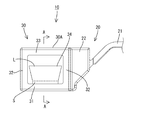
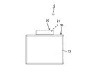
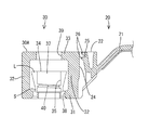
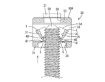
ボルト用クリップ10は、合成樹脂製(例えば、ポリプロピレン)であって、図1に示すように、ワイヤハーネス(図示せず)を結束する結束バンド部20、この結束バンド部20と一体に設けられたボルト固定部30などを備えて構成されている。なお、結束バンド部20とボルト固定部30は、射出成形により一体に成形されている。
The
結束バンド部20は、バンド部21と、バンド固定部22とを備えて構成されている。バンド部21は、複数のワイヤハーネスを束ねることができる長さであって、ほぼ一定の幅寸法でバンド固定部22に連なっている。バンド部21は可撓性を有し、バンド部21におけるワイヤハーネスとの接触面には、複数の係止凸部23が長さ方向に連続して設けられている。一方、バンド固定部22は、ボルト固定部30の側面部32と一体に設けられている。
The
バンド固定部22には、図2に示すように、上下方向に貫通する形態をなすバンド挿通孔24が設けられており、このバンド挿通孔24の内部には、ロック片25が設けられている。このロック片25は、図6に示すように、バンド挿通孔24の内壁から上方に向けて片持ち状に突出する形態をなしている。ロック片25とバンド挿通孔24の内壁との間には、ロック片25の撓み空間が確保されている。このため、ロック片25は、バンド挿通孔24の内部で撓み可能とされている。
As shown in FIG. 2, the
ロック片25の先端部には、複数の被係止凸部26が設けられている。バンド部21がバンド挿通孔24に下方から挿入されると、バンド部21の先端部によってロック片25が撓み変形するとともに、バンド部21の係止凸部23とロック片25の被係止凸部26とが係止することにより、バンド部21がバンド挿通孔24から下方へ抜け止めされた状態に保持される。これにより、複数のワイヤハーネスが結束バンド部20によって結束される。
A plurality of locked
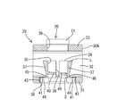
ボルト固定部30は、図1に示すように、角筒状をなす筒部30Aを有し、この筒部30Aは、基板部31と、基板部31の両側縁から立ち上がる一対の側面部32,32と、両側面部32,32の上縁同士を連結してなる上面部33とを備えて構成されている。筒部30Aの内部には、ロック部34が配置されている。このロック部34は略円筒状をなし、側方から見た場合に、上方に向かうほど外径が大きくなるアンダーカット形状の外周面を有している。一方、ロック部34の内部には、嵌合孔35が設けられており、この嵌合孔35は、上下方向に内径が一定とされた内周面を有している。
As shown in FIG. 1, the
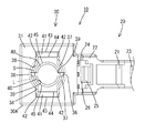
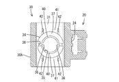
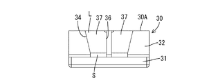
ロック部34は、図7および図8に示すように、左右一対のスリット36,36によって一対の楔部材37,37に分割されている。楔部材37は、上方に向かうほど肉厚を増すようにして楔状に形成されている。楔部材37の上端の肉厚は、挿通孔38の内周面からスタッドボルトSBのねじ山の頂点までの離間距離よりも大きく、楔部材37の下端の肉厚は、同離間距離よりも小さい。したがって、基板部31に近づくようにして楔部材37が下方に相対移動した場合には、楔部材37が、挿通孔38の内周面とスタッドボルトSBとの間で楔状に嵌り込み、楔部材37の外周面が挿通孔38の孔縁部に当接することになる。
As shown in FIGS. 7 and 8, the
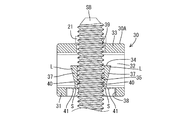
スリット36は、上下方向に延びる形態をなしている。前記したようにロック部34の内部には、図5および図6に示すように、スタッドボルトSBが嵌合可能な嵌合孔35が上下方向に貫通して形成されている。ロック部34の下端部は小径部Sとされており、ロック部34の上端部は大径部Lとされている。ロック部34を上下方向に切断した断面は、小径部Sから大径部Lにかけて徐々に肉厚が増す楔状とされている。
The
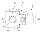
嵌合孔35の内周面は、図6に示すように、上下方向に延びる形態とされている。また、嵌合孔35の内周面には、突起40が全周に亘って形成されている。この突起40は、図10および図11に示すように、スタッドボルトSBのねじ溝に適合して嵌り込むようにやや斜めに延びる形態とされている。突起40の突出高さは、スタッドボルトSBのねじ溝の深さとほぼ同じとされている。また、嵌合孔35の孔径は、スタッドボルトSBの外径とほぼ同じかこれよりやや大きめとされている。このため、スタッドボルトSBが嵌合孔35に嵌合した状態では、突起40がスタッドボルトSBのねじ溝に全周に亘って嵌り込んで上下方向に係止することにより、ボルト固定部30がスタッドボルトSBに取り付け固定されるようになっている。
As shown in FIG. 6, the inner peripheral surface of the
基板部31には、図6に示すように、スタッドボルトSBを挿通させる挿通孔38が上下方向に貫通して形成されている。一方、上面部33には、挿通孔38と同軸をなす位置にスタッドボルトSBを挿通させる逃がし孔39が上下方向に貫通して形成されている。この逃がし孔39は、挿通孔38の孔径よりも小径でかつ嵌合孔35の孔径よりも大径とされている。このため、スタッドボルトSBが逃がし孔39に挿通された状態で、ボルト固定部30がスタッドボルトSBの側方から力を受けた場合であっても、ボルト固定部30の傾きが規制されるとともに、スタッドボルトSBが逃がし孔39の内周面に当接し、ロック部34のうち突起40とスタッドボルトSBのねじ溝との係止部分が直接力を受けることを回避できる。したがって、ロック部34の突起40がスタッドボルトSBのねじ溝に嵌り込んだ状態に保持することができる。
As shown in FIG. 6, an
楔部材37における小径部S側の端部は、図5に示すように、薄肉のヒンジ部41を介して基板部31に連結されている。ヒンジ部41は、基板部31の下面側を肉抜きすることで薄肉に形成された平面状とされており、可撓性および伸縮性を備えている。ヒンジ部41は、図3に示すように、左右一対の切り込み42,42によって基板部31と分離されており、両切り込み42,42の奥端同士を直線状に結んだ連結縁43において基板部31と連結されている。これにより、楔部材37は、図12に示すように、下方に平行移動可能であって、図9に示すように、楔部材37における大径部L側の端部がヒンジ部41を中心として径方向外側に開き変位可能となっている。
As shown in FIG. 5, the end of the
ヒンジ部41における連結縁43よりも楔部材37側には、図3に示すように、段差44が形成されている。段差44は、連結縁43と平行に配置されている。ヒンジ部41のうち段差44よりも内側部分は、外側部分よりも厚肉となっている。また、ヒンジ部41のうち楔部材37側の端縁45は円弧状をなし、この端縁45の左右両端部は、両切り込み42,42よりも左右両側へ突出する形態とされている。これにより、図12に示すように、楔部材37が挿通孔38の軸方向に平行移動した際に、楔部材37の外周面が挿通孔38の孔縁部に当接して係合し、基板部31が楔部材37を乗り越えて抜けることが規制されている。
As shown in FIG. 3, a
また、楔部材37の外周面が挿通孔38の孔縁部に係合した状態では、突起40が挿通孔38の内部に配置されているため、楔部材37が挿通孔38の孔縁部から受ける径方向内側への力を突起40に直接伝えることができる。したがって、突起40が径方向内側に押し込まれてスタッドボルトSBのねじ溝に嵌り込み、スタッドボルトSBに対してボルト固定部30を強固に固定することができる。
Further, in a state where the outer peripheral surface of the
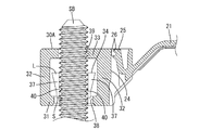
本実施形態は以上のような構成であって、続いてその作用を図9ないし図12の図面を参照しながら説明する。ボルト固定部30をスタッドボルトSBに取り付けるには、スタッドボルトSBの先端を挿通孔38から挿入し、嵌合孔35に差しかかったところで、スタッドボルトSBの先端が両楔部材37,37の両突起40,40に接触し始める。そのまま嵌合孔35にスタッドボルトSBを挿入していくと、両楔部材37,37の上端部が両ヒンジ部41,41を中心として互いに離れる方向に開き変位することで、スタッドボルトSBを嵌合孔35に挿入する際の挿入力が低減される。
This embodiment is configured as described above, and its operation will be described with reference to FIGS. 9 to 12. In order to attach the
そして、スタッドボルトSBの挿入が完了すると、図10および図11に示すように、両突起40,40がスタッドボルトSBのねじ溝に嵌り込み、両楔部材37,37の上端部が復帰変位する。この状態では、両突起40,40がスタッドボルトSBのねじ溝のほぼ全周に亘って嵌っているため、ボルト固定部30がスタッドボルトSBに固定される。
When the insertion of the stud bolt SB is completed, as shown in FIGS. 10 and 11, both the
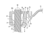
次に、ボルト固定部30がスタッドボルトSBの先端側に強く引っ張られた場合について説明する。この場合、図12に示すように、ロック部34が挿通孔38の内周面とスタッドボルトSBとの間で楔状に嵌り込み、ロック部34の外周面が挿通孔38の孔縁部に当接することになる。ここで、ロック部34の大径部Lは、挿通孔38の孔径よりも大径とされているため、両楔部材37,37の外周面と挿通孔38の孔縁部とが軸方向および径方向の双方向に係合し、筒部30Aがロック部34から上方に抜けることが規制される。また、両楔部材37,37と挿通孔38の孔縁部との係合に伴って両突起40,40をスタッドボルトSBのねじ溝に押し込むように作用するから、両突起40,40がスタッドボルトSBのねじ溝から外れることはなく、ボルト固定部30をスタッドボルトSBに対して強固に固定することができる。
Next, the case where the bolt fixing | fixed
以上のように本実施形態ではボルト固定部30がスタッドボルトSBの先端側に強く引っ張られた場合に、ロック部34が基板部31側に相対移動して挿通孔38に楔状に嵌り込み、両突起40,40がスタッドボルトSBのねじ溝に押し込まれるようにしたから、ボルト固定部30がスタッドボルトSBから外れてしまうことを規制できる。また、ロック部34を両楔部材37,37で構成し、楔部材37を基板部31に対してヒンジ部41で連結したから、スタッドボルトSBを嵌合孔35に挿入する際に、両楔部材37,37が両ヒンジ部41,41を中心として開くことになり、スタッドボルトSBの嵌合孔35への挿入力を低減できる。
As described above, in this embodiment, when the
また、ボルト固定部30に筒部30Aを設けたから、ボルト固定部30の剛性を高めることができる。さらに、上面部33にスタッドボルトSBを挿通させる逃がし孔39を設けたから、スタッドボルトSBの先端部が上面部33に干渉することを回避できる。これらに加えて、ボルト固定部30がスタッドボルトSBの側方から力を受けた場合に、スタッドボルトSBが逃がし孔39の内周面に当接することにより、ロック部34に力がかかることを規制できる。
Further, since the
<他の実施形態>
本発明は上記記述及び図面によって説明した実施形態に限定されるものではなく、例えば次のような実施形態も本発明の技術的範囲に含まれる。
(1)上記実施形態ではロック部34が円筒状に形成されているものの、本発明によると、ロック部34を角筒状に形成してもよく、その場合には挿通孔を角孔にすればよい。
<Other embodiments>
The present invention is not limited to the embodiments described with reference to the above description and drawings. For example, the following embodiments are also included in the technical scope of the present invention.
(1) Although the
(2)上記実施形態ではロック部34が両ヒンジ部41,41を介して基板部31に連結されているものの、本発明によると、ロック部を基板部とは別体に設けてもよい。
(2) Although the
(3)上記実施形態ではボルト固定部30が筒部30Aを有しているものの、本発明によると、ボルト固定部が基板部とロック部のみからなる構成としてもよい。
(3) Although the
(4)上記実施形態では逃がし孔39が挿通孔38の孔径よりも大径でかつ嵌合孔35の孔径よりも小径とされているものの、本発明によると、スタッドボルトの形状に合わせて逃がし孔の孔径を適宜設定することができる。
(4) Although the
10…ボルト用クリップ
30…ボルト固定部
30A…筒部
31…基板部
32…側面部
33…上面部
34…ロック部
35…嵌合孔
37…楔部材
38…挿通孔
39…逃がし孔
40…突起
41…ヒンジ部
SB…スタッドボルト(ボルト)
DESCRIPTION OF
Claims (4)
前記ボルトに取り付け固定されるボルト固定部は、
前記ボルトを挿通させる挿通孔を有する基板部と、
前記ボルトが嵌合可能な嵌合孔を有し、この嵌合孔の内周面に前記ボルトのねじ溝に嵌って前記ボルトを抜け止めする突起が設けられており、前記基板部に対して前記挿通孔の軸方向に相対移動可能なロック部とを備えて構成され、
前記ロック部は、前記基板部が前記ボルトの先端側へ引っ張られた際に、前記挿通孔の内面と前記ボルトとの間で楔状に嵌り込んで前記挿通孔の孔縁部に係合することを特徴とするボルト用クリップ。 A bolt clip which is attached to a bolt protruding from a member to be attached and holds a wire harness,
The bolt fixing portion fixed to the bolt is
A substrate portion having an insertion hole through which the bolt is inserted;
The bolt has a fitting hole into which the bolt can be fitted, and an inner peripheral surface of the fitting hole is provided with a protrusion that fits into a screw groove of the bolt and prevents the bolt from coming off. A lock portion that is relatively movable in the axial direction of the insertion hole,
The lock portion is fitted in a wedge shape between the inner surface of the insertion hole and the bolt and engaged with a hole edge portion of the insertion hole when the substrate portion is pulled toward the tip end side of the bolt. Bolt clip characterized by.
前記上面部には、前記挿通孔と同軸をなす位置に前記ボルトを挿通させる逃がし孔が設けられていることを特徴とする請求項1または請求項2に記載のボルト用クリップ。 The bolt fixing part has a cylindrical part formed in a cylindrical shape by the base part, a pair of side parts rising from a side edge of the base part, and an upper part formed by connecting upper edges of both side parts. The lock portion is arranged inside the cylindrical portion,
The bolt clip according to claim 1 or 2, wherein an escape hole through which the bolt is inserted is provided in the upper surface portion at a position coaxial with the insertion hole.
Priority Applications (1)
| Application Number | Priority Date | Filing Date | Title |
|---|---|---|---|
| JP2011082939A JP2012219829A (en) | 2011-04-04 | 2011-04-04 | Bolt clip |
Applications Claiming Priority (1)
| Application Number | Priority Date | Filing Date | Title |
|---|---|---|---|
| JP2011082939A JP2012219829A (en) | 2011-04-04 | 2011-04-04 | Bolt clip |
Publications (1)
| Publication Number | Publication Date |
|---|---|
| JP2012219829A true JP2012219829A (en) | 2012-11-12 |
Family
ID=47271591
Family Applications (1)
| Application Number | Title | Priority Date | Filing Date |
|---|---|---|---|
| JP2011082939A Withdrawn JP2012219829A (en) | 2011-04-04 | 2011-04-04 | Bolt clip |
Country Status (1)
| Country | Link |
|---|---|
| JP (1) | JP2012219829A (en) |
Cited By (1)
| Publication number | Priority date | Publication date | Assignee | Title |
|---|---|---|---|---|
| WO2025195172A1 (en) * | 2024-03-21 | 2025-09-25 | 欣旺达动力科技股份有限公司 | Battery pack and electrical device |
-
2011
- 2011-04-04 JP JP2011082939A patent/JP2012219829A/en not_active Withdrawn
Cited By (1)
| Publication number | Priority date | Publication date | Assignee | Title |
|---|---|---|---|---|
| WO2025195172A1 (en) * | 2024-03-21 | 2025-09-25 | 欣旺达动力科技股份有限公司 | Battery pack and electrical device |
Similar Documents
| Publication | Publication Date | Title |
|---|---|---|
| US8245367B2 (en) | Fastener | |
| JP4976708B2 (en) | Fitting | |
| US9356398B2 (en) | Lock mechanism of shield connector | |
| JP2012095434A (en) | Band clip | |
| JP2019032059A (en) | clip | |
| JP5831827B1 (en) | Electric wire housing protector | |
| JP2011226508A (en) | Bracket and metal collar | |
| JP4816959B2 (en) | Fog lamp mounting structure and mounting method thereof | |
| JP2017073300A (en) | connector | |
| JP2013074681A (en) | Electric connection box | |
| JP2012219829A (en) | Bolt clip | |
| JP6243701B2 (en) | Mounting member mounting structure | |
| JP2017163717A (en) | Binding band and fixing structure of wire harness using the same | |
| CN107534280A (en) | Wire Storage Protector | |
| JP7235570B2 (en) | clamp | |
| JP2012235575A (en) | Protector | |
| JP2009117286A (en) | Connection structure between terminal metal fitting and shielded electric wire | |
| KR20170015148A (en) | Fastener | |
| JP2016207253A (en) | Connector and terminal fitting connection structure | |
| CN107199952B (en) | Fixing structure | |
| JP2009144772A (en) | Clamp misassembly prevention structure | |
| JP2011015508A (en) | Electrical junction box | |
| JP2011202777A (en) | Binding band | |
| JP5488905B2 (en) | Terminal connection structure | |
| JP2016219308A (en) | connector |
Legal Events
| Date | Code | Title | Description |
|---|---|---|---|
| A300 | Withdrawal of application because of no request for examination |
Free format text: JAPANESE INTERMEDIATE CODE: A300 Effective date: 20140701 |