JP2012217153A - Communication device, communication system, and communication method - Google Patents
Communication device, communication system, and communication method Download PDFInfo
- Publication number
- JP2012217153A JP2012217153A JP2012055568A JP2012055568A JP2012217153A JP 2012217153 A JP2012217153 A JP 2012217153A JP 2012055568 A JP2012055568 A JP 2012055568A JP 2012055568 A JP2012055568 A JP 2012055568A JP 2012217153 A JP2012217153 A JP 2012217153A
- Authority
- JP
- Japan
- Prior art keywords
- bits
- communication
- transmission data
- duplicating
- bit length
- Prior art date
- Legal status (The legal status is an assumption and is not a legal conclusion. Google has not performed a legal analysis and makes no representation as to the accuracy of the status listed.)
- Pending
Links
Images


Abstract
【課題】第三者による通信内容の傍受可能範囲を制限しつつ、無線通信装置と通信可能な正規の端末装置の範囲制限が緩和され、遠距離においても、無線通信装置と正規の端末装置の通信が可能な通信装置、通信システムおよび通信方法を提供することを目的とする。
【解決手段】受信した冗長なデータに対して、送信側と同じ符号を作用させた後に積分を行って、送信側の変調方式に対応する復調方式を用いてデータを復調する。積分出力について、上限と下限の閾値を設定して、積分出力が上限の閾値より大きい場合には、通信相手の送信電力を下げ、積分出力が下限の閾値よりも小さい場合には、作用させる符合の長さを長くする。
【選択図】図7The range restriction of a legitimate terminal device capable of communicating with a wireless communication device is relaxed while restricting the range in which communication contents can be intercepted by a third party, and the wireless communication device and the legitimate terminal device can be connected at a long distance. An object is to provide a communication device, a communication system, and a communication method capable of communication.
The received redundant data is integrated after applying the same code as that on the transmission side, and the data is demodulated using a demodulation method corresponding to the modulation method on the transmission side. For the integral output, set the upper and lower thresholds.If the integral output is larger than the upper threshold, the transmission power of the communication partner is lowered.If the integral output is smaller than the lower threshold, the code to be acted on. Increase the length of.
[Selection] Figure 7
Description
本発明は、相手装置と通信する際に、通信する情報の守秘性を確保するための通信装置、通信システムおよび通信方法に関するものである。 The present invention relates to a communication device, a communication system, and a communication method for ensuring confidentiality of information to be communicated when communicating with a counterpart device.
図15は、(特許文献1)に記載された、守秘性を確保したい通信の処理動作を示す図である。 FIG. 15 is a diagram illustrating a communication processing operation described in (Patent Document 1) in which confidentiality is to be ensured.
以上のような処理フローを有する無線通信装置について、その動作(特許文献1に記載された動作)を説明する。 The operation (operation described in Patent Document 1) of the wireless communication apparatus having the processing flow as described above will be described.
新たに通信したい端末装置がいた場合、無線通信装置を登録モードに設定する。登録モードに設定すると、出力電力を減少させることによって、距離の近い通信装置のみが登録可能になり、距離の遠い他の端末装置を排除することが出来る。そして、端末装置からリンク接続要求が受信できれば、リンクは確立するが、リンク接続要求が受信できなければ、再送を繰り返す。これらの処理により、登録作業におけるセキュリティ上の管理が容易になるが、無線通信装置から送信される登録情報を、登録を希望する正規の端末装置が受信可能な範囲が制限される。 When there is a new terminal device that wants to communicate, the wireless communication device is set to the registration mode. When the registration mode is set, by reducing the output power, only communication devices with a short distance can be registered, and other terminal devices with a long distance can be excluded. If the link connection request can be received from the terminal device, the link is established, but if the link connection request cannot be received, retransmission is repeated. These processes facilitate security management in registration work, but limit the range in which registration information transmitted from a wireless communication apparatus can be received by a legitimate terminal apparatus that desires to register.
本発明が解決しようとしている課題は、第三者による通信内容の傍受可能範囲を制限しつつ、無線通信装置と通信可能な正規の端末装置の範囲制限が緩和され、遠距離においても、無線通信装置と正規の端末装置の通信が可能な通信装置、通信システムおよび通信方法を提供することである。 The problem to be solved by the present invention is to limit the range of legitimate terminal devices that can communicate with a wireless communication device while limiting the range in which communication contents can be intercepted by a third party. It is to provide a communication device, a communication system, and a communication method capable of communication between a device and a regular terminal device.
上記課題を解決するために、本発明は、他の通信装置と通信を行う通信装置であって、Nビットの送信データをMビットのビット長に複製する複製手段と(Nは1以上の整数、Mは2以上の整数、N<M)、複製手段により複製された送信データに乱数を乗算する乗算手段と、乗算手段により乱数が乗算された送信データを他の通信装置に送信する送信手段とを備え、複製手段は、他の通信装置からの受信電力に応じて、送信データを複製するビット長をMビットからKビットに変更し(Kは1以上の整数、K≠M)、Nビットの送信データをKビットのビット長に複製する。 In order to solve the above-described problems, the present invention provides a communication device that communicates with another communication device, and includes a duplication unit that duplicates N-bit transmission data into an M-bit bit length (N is an integer of 1 or more). , M is an integer of 2 or more, N <M), multiplication means for multiplying the transmission data duplicated by the duplication means by a random number, and transmission means for sending the transmission data multiplied by the random number by the multiplication means to another communication device The duplicating means changes the bit length for duplicating transmission data from M bits to K bits according to the received power from other communication devices (K is an integer of 1 or more, K ≠ M), N Bit transmission data is duplicated to a bit length of K bits.
本発明によれば、第1の発明によれば、受信電力が変動した場合であっても、セキュリティを確保しながら第三者へのS/N比を上げることなく、正規の受信者へのS/N比のみを向上させることが出来る。 According to the present invention, according to the first invention, even if the received power fluctuates, it is possible to ensure the security of a legitimate recipient without increasing the S / N ratio to a third party while ensuring security. Only the S / N ratio can be improved.
上記課題を解決するためになされた第1の発明は、他の通信装置と通信を行う通信装置であって、Nビットの送信データをMビットのビット長に複製する複製手段と(Nは1以上の整数、Mは2以上の整数、N<M)、複製手段により複製された送信データに乱数を乗算する乗算手段と、乗算手段により乱数が乗算された送信データを他の通信装置に送信する送信手段とを備え、複製手段は、他の通信装置からの受信電力に応じて、送信データを複製するビット長をMビットからKビットに変更し(Kは1以上の整数、K≠M)、Nビットの送信データをKビットのビット長に複製する通信装置である。 A first invention made to solve the above-described problem is a communication device that communicates with another communication device, and a duplication unit that duplicates N-bit transmission data to an M-bit bit length (N is 1). The above integer, M is an integer of 2 or more, N <M), the transmission means replicated by the replicating means is multiplied by a random number, and the transmission data multiplied by the random number is transmitted to another communication device. And the duplicating unit changes the bit length for duplicating the transmission data from M bits to K bits according to the received power from another communication device (K is an integer of 1 or more, K ≠ M ), A communication device that replicates N-bit transmission data to a bit length of K bits.
第1の発明によれば、受信電力が変動した場合であっても、セキュリティを確保しながら第三者へのS/N比を上げることなく、正規の受信者へのS/N比のみを向上させることが出来る。 According to the first invention, even when the received power fluctuates, only the S / N ratio to the legitimate receiver is increased without increasing the S / N ratio to a third party while ensuring security. Can be improved.
上記課題を解決するためになされた第2の発明は、第1の発明であって、複製手段は、受信電力が所定値より小さい場合に、送信データが複製されるビット長をKビット(M<K)に変更する通信装置である。 A second invention made to solve the above problem is the first invention, wherein the duplicating means sets a bit length for duplicating transmission data to K bits (M) when the received power is smaller than a predetermined value. The communication device is changed to <K).
第2の発明によれば、受信電力が低下した場合に、正規の受信者へのS/N比低下を抑制することが出来る。 According to the second invention, when the reception power is reduced, it is possible to suppress a decrease in the S / N ratio to a normal receiver.
上記課題を解決するためになされた第3の発明は、第2の発明であって、さらに、送信データの電力を制御する送信電力制御手段を備え、送信電力制御手段は、受信電力が所定値より小さい場合に、送信電力を低下させる通信装置である。 3rd invention made | formed in order to solve the said subject is 2nd invention, Comprising: The transmission power control means which controls the electric power of transmission data is further provided, and transmission power control means is the reception power is predetermined value. In the case of being smaller, the communication device reduces the transmission power.
第3の発明によれば、ビット長を長く変更することなく、送信電力を低下することで、オーバーヘッドの増大を抑制しながら、通信エリアの不要な拡大を防止することが出来る。 According to the third invention, it is possible to prevent unnecessary expansion of the communication area while suppressing an increase in overhead by reducing the transmission power without changing the bit length long.
上記課題を解決するためになされた第4の発明は、第3の発明であって、送信電力制御手段は、受信電力が第1の閾値より小さい場合に、送信データの電力を低下大させ、複製手段は、受信電力が第1の閾値より小さい第2の閾値より小さい場合に、送信データを複製するビット長を変更する通信装置である。 4th invention made | formed in order to solve the said subject is 3rd invention, Comprising: When reception power is smaller than a 1st threshold value, transmission power control means reduces the power of transmission data large, The duplication unit is a communication device that changes the bit length for duplicating transmission data when the received power is smaller than a second threshold value that is smaller than the first threshold value.
第4の発明によれば、受信電力が低下する場合に、送信データの電力を優先した上で、乱数を乗算する送信データの複製範囲を変更するので、通信エリアの不要な拡大を防止した上で、その通信エリア内に存在する正規の受信者へのS/N比低下を抑制することが出来る。 According to the fourth invention, when the reception power is reduced, the transmission data replication range is changed after giving priority to the transmission data power, thereby preventing unnecessary expansion of the communication area. Thus, it is possible to suppress a decrease in the S / N ratio to a normal receiver existing in the communication area.
上記課題を解決するためになされた第5の発明は、第1ないし4いずれかの発明であって、受信電力は信号成分のみの電力である通信装置である。 A fifth invention made to solve the above-mentioned problems is any one of the first to fourth inventions, wherein the received power is a power of only a signal component.
第5の発明によれば、ノイズなどの外因を除外することが出来るので、正規の受信者へのS/N比が低下する場合に、S/N比を向上させることが出来る。 According to the fifth aspect, since external factors such as noise can be excluded, the S / N ratio can be improved when the S / N ratio to a regular receiver is lowered.
上記課題を解決するためになされた第6の発明は、第1の発明であって、さらに、他の通信装置からMビットの受信データを受信する受信手段を備え、乗算手段は、さらに、前記受信データに乱数を乗算し、複製手段は、さらに、乱数が乗算された受信データのビット長をMビットからNビットに短縮し、複製手段は、受信データの電力に応じて、送信データを複製するビット長とともに、受信データに乗算される乱数のビット長をMビットからKビットに変更する通信装置。 6th invention made | formed in order to solve the said subject is 1st invention, Comprising: The receiving means which receives the reception data of M bit from another communication apparatus is further provided, and a multiplication means is further the said The received data is multiplied by a random number, and the duplicating means further shortens the bit length of the received data multiplied by the random number from M bits to N bits, and the duplicating means duplicates the transmission data according to the power of the received data. The communication apparatus changes the bit length of the random number multiplied to the received data from M bits to K bits along with the bit length to be received.
第6の発明によれば、ノイズなどの外因を除外することが出来るので、正規の受信者へのS/N比が低下する場合に、S/N比を向上させることが出来る。 According to the sixth aspect of the invention, since external factors such as noise can be excluded, the S / N ratio can be improved when the S / N ratio to the regular receiver is lowered.
上記課題を解決するためになされた第7の発明は、他の通信装置と通信を行う通信方法であって、Nビットの送信データをMビットのビット長に複製し(Nは1以上の整数、Mは2以上の整数、N<M)、複製された送信データに乱数を乗算し、乱数が乗算された送信データを他の通信装置に送信し、送信データを複製する場合において、他の通信装置からの受信電力に応じて、送信データを複製するビット長をMビットからKビットに変更し(Kは1以上の整数、K≠M)、Nビットの送信データをKビットのビット長に複製する通信方法。 A seventh invention made to solve the above-mentioned problem is a communication method for communicating with another communication device, wherein N-bit transmission data is duplicated into an M-bit bit length (N is an integer of 1 or more). , M is an integer greater than or equal to 2, N <M), when the replicated transmission data is multiplied by a random number, the transmission data multiplied by the random number is transmitted to another communication device, The bit length for duplicating transmission data is changed from M bits to K bits according to the received power from the communication device (K is an integer of 1 or more, K ≠ M), and N bits of transmission data are K bits in length. The communication method to replicate to.
第7の発明によれば、受信電力が変動した場合であっても、セキュリティを確保しながら第三者へのS/N比を上げることなく、正規の受信者へのS/N比のみを向上させることが出来る。 According to the seventh invention, even when the received power fluctuates, only the S / N ratio to the legitimate receiver is obtained without increasing the S / N ratio to a third party while ensuring security. Can be improved.
上記課題を解決するためになされた第8の発明は、送信装置および受信装置を有する通信システムであって、送信装置は、Nビットの送信データをMビットのビット長に複製する複製手段と(Nは1以上の整数、Mは2以上の整数、N<M)、複製手段により複製された送信データに乱数を乗算する第1の乗算手段と、第1の乗算手段により乱数が乗算された送信データを受信装置に送信する送信手段とを備え、複製手段は、受信電力に応じて、送信データを複製するビット長をMビットからKビットに変更し(Kは1以上の整数、K≠M)、Nビットの送信データをKビットのビット長に複製し、受信装置は、送信装置からMビットの受信データを受信する受信手段と、受信データに乱数を乗算する第2の乗算手段と、乱数が乗算された受信データのビット長をMビットからNビットに短縮する短縮手段とを備え、短縮手段は、受信電力に応じて、送信データを複製するビット長とともに、受信データに乗算される乱数のビット長をMビットからKビットに変更し、Kビットの送信データをNビットのビット長に短縮することを特徴とする通信システム。 An eighth invention made to solve the above-described problem is a communication system having a transmission device and a reception device, wherein the transmission device includes a duplicating unit that duplicates N-bit transmission data into an M-bit bit length ( N is an integer greater than or equal to 1, M is an integer greater than or equal to 2, N <M), the first multiplication means for multiplying the transmission data duplicated by the duplication means by a random number, and the first multiplication means multiplied by the random number Transmitting means for transmitting the transmission data to the receiving device, and the duplicating means changes the bit length for duplicating the transmission data from M bits to K bits according to the received power (K is an integer of 1 or more, K ≠ M), replicating N-bit transmission data into a K-bit bit length, and the receiving device receiving means for receiving M-bit received data from the transmitting device; and second multiplying means for multiplying the received data by a random number; , Received with a random number A shortening unit that shortens the bit length of the data from M bits to N bits, and the shortening unit sets the bit length of the random number multiplied by the received data together with the bit length for duplicating the transmission data according to the received power. A communication system, wherein the bit is changed from K bit to K bit, and the K bit transmission data is shortened to N bit length.
第8の発明によれば、受信電力が変動した場合であっても、セキュリティを確保しながら第三者へのS/N比を上げることなく、正規の受信者へのS/N比のみを向上させることが出来る。 According to the eighth aspect of the invention, even if the received power fluctuates, only the S / N ratio to the legitimate receiver is obtained without increasing the S / N ratio to a third party while ensuring security. Can be improved.
上記課題を解決するためになされた第9の発明は、第8の発明であって、受信装置は、さらに、乱数が乗算された受信データを鍵シーケンスとしてマスター鍵を生成するマスター鍵生成手段を備える通信システム。 A ninth invention made to solve the above-mentioned problem is the eighth invention, wherein the receiving device further comprises a master key generating means for generating a master key using the received data multiplied by the random number as a key sequence. A communication system provided.
第9の発明によれば、鍵シーケンスとして、伝送誤りの情報を利用することが出来るので、マスター鍵の予測を困難にすることが出来る。 According to the ninth aspect, since transmission error information can be used as the key sequence, it is difficult to predict the master key.
上記課題を解決するためになされた第10の発明は、第9の発明であって、記受信データは第1の値および第2の値の2値を含み、マスター鍵生成手段は、さらに、受信データにおいて第1の値のビット数と第2の値のビット数の差が所定値以下の場合に、乱数が乗算された受信データを鍵シーケンスとしてマスター鍵を生成する通信システム。 A tenth invention made to solve the above-mentioned problem is the ninth invention, wherein the received data includes a binary value of a first value and a second value, and the master key generating means further comprises: A communication system that generates a master key using received data multiplied by a random number as a key sequence when the difference between the number of bits of a first value and the number of bits of a second value is equal to or less than a predetermined value in received data.
第10の発明によれば、第1の値および第2の値の分布に適度なバランスに設定することが出来るので、鍵シーケンスKを用いた暗号鍵の推測を困難にすることが出来る。 According to the tenth aspect, since the distribution of the first value and the second value can be set to an appropriate balance, it is difficult to guess the encryption key using the key sequence K.
(実施の形態1)
以下、本発明の具体的な内容について実施の形態1を用いて説明する。
(Embodiment 1)
Hereinafter, specific contents of the present invention will be described using the first embodiment.
本発明の実施の形態1について図1、2、3、4、5、6、7、8、9、10、11、12、13および14を用いて説明する。
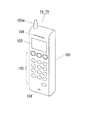
図1は、通信端末を示す外観斜視図である。 FIG. 1 is an external perspective view showing a communication terminal.
本実施の形態1における通信端末1a、1bは、通信装置の一例であって、図1に示すように、携帯可能な電話器である。通信端末1a、1bは筐体101を有しており、筐体101には、電話番号などを表示するLCD(Liquid Crystal Display)102と、電話番号を指定するためのボタンなどで構成されるキーマトリックス103と、マイク104と、電波を送受信する外部アンテナ105aと、話し相手からの音声を出力するスピーカ106とが設けられている。なお、通信端末の一例として、図1の電話器を示したが、特に電話器に限る必要はなく、通信端末は、アクセスポイントを含む他の通信端末と接続可能な機能を備えた機器(例えばパーソナルコンピュータなどの電子機器)であってもよい。
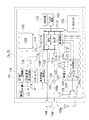
図2は、通信端末のハードウェアの一例を示すブロック図である。 FIG. 2 is a block diagram illustrating an example of hardware of the communication terminal.
通信端末1a、1bは、図2に示すように、破線で示す筐体101内に、回路モジュール110を有している。回路モジュール110には、図1で説明したLCD102やキーマトリックス103の他、ベースバンドIC(Integrated Circuit)111と、無線モジュール124とが実装されている。
As shown in FIG. 2, the
ベースバンドIC111は、CPU(Central Proccessing Unit)111aと、音声処理を行うVoIP(Voice over Internet
Protocol)ブロック111bと、無線LAN(Local Area Network)のMAC(Medium Access Control)層を制御する無線MACブロック111cと、メインバス111dやローカルバス111eなどのバスとを有している。
The baseband IC 111 includes a CPU (Central Processing Unit) 111a and a VoIP (Voice over Internet) that performs voice processing.
ベースバンドIC111内のCPU111a、VoIPブロック111b、および無線MACブロック111cは、メインバス111dを介して、SDRAM(Synchronous Dynamic Random Access Memory)112、およびFlash ROM(Flash Read Only Memory)113に接続されている。また、CPU111aは、ローカルバス111eを介して、LCD102、LCDの電源を制御するLCD電源制御IC114、必要なDC(Direct Current)電圧に変換するDC−DC(Direct Current to Direct Current)変換器116、初期化信号を通知するリセットIC118および、電池121に接続され電池121の電圧を測定することにより電池残量が少なくなったことを通知する電池残量検知IC120に接続されている。DC−DC変換器116は、ダイオード119を介して電池121に接続され、リセットIC118、および、LCD102に必要な電圧に昇圧するLCD電源用昇圧回路117は、電池121に接続されている。
The
また、CPU111a、およびVoIPブロック111bは、ローカルバス111eを介して、マイク104からの信号を増幅するアンプ122、および、スピーカ106への信号を増幅するアンプ123に接続されている。アンプ122、123はそれぞれ、マイク104およびスピーカ106に接続されている。さらに、ベースバンドIC111は、キーマトリックス103、ベースバンドICにクロックを供給する発振器115、無線モジュール124、および使用するアンテナをベースバンドIC111から切り替えるアンテナ切り替えSW(SWitch)126に接続されている。
The
無線モジュール124は、送受信切り替えSW124aと、受信信号を増幅するLNA(Low Noise Amplifier)124bと、送信信号を増幅するPA(Power Amplifier)124cと、無線信号への変調および無線信号からの復調を行うRF(Radio Frequency)変復調器124dとを有している。また、無線モジュール124は、無線モジュール124にクロックを供給する発振器125、およびアンテナ切り替えSW126に接続されている。アンテナ切り替えSW126は、図1で説明した外部アンテナ105aと、内部アンテナ105bとに接続されている。
The
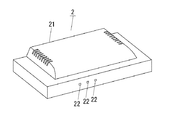
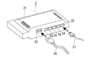
図3は、管理端末(前面)を示す外観斜視図、図4は、管理端末(背面)を示す外観斜視図である。 FIG. 3 is an external perspective view showing the management terminal (front side), and FIG. 4 is an external perspective view showing the management terminal (back side).
本実施の形態1における管理端末2は、通信装置の他の一例であって、図3に示すようにルータである。管理端末2は、筐体21を有しており、筐体21の前面には、LED(Light Emitting Diode)などの表示部22が設けられている。筐体21の背面には、図4に示すように、DC電源コネクタ23、RJ45などLAN用モジュラージャック24、およびWAN(Wide Area Network)用モジュラージャック25が設けられている。DC電源コネクタ23には、図4に示すように、平行ケーブルなどの電力線26が接続される。LAN用モジュラージャック24および、WAN用モジュラージャック25には、LANケーブル27が接続される。なお、管理端末の一例として、図3および図4のルータを示したが、特にこれに限る必要はなく、管理端末は、アクセスポイントの機能を備えた機器(例えばテレビなどの家電機器)であってもよい。
The
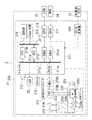
図5は、管理端末のハードウェアの一例を示すブロック図である。 FIG. 5 is a block diagram illustrating an example of hardware of the management terminal.
管理端末2は、図5に示すように、破線で示す筐体21内に、回路モジュール210を有している。回路モジュール210には、メインIC211と、無線LANコントローラ219と、無線モジュール220とが実装されている。
As shown in FIG. 5, the
メインIC211は、CPU211aと、メインバス211fやローカルバス211gなどのバスと、バス上のデータの流れを制御するBCU(Bus Control Unit)211bと、Ethernet(登録商標)のMAC層を制御するMACブロック(EMAC)211c、211dと、PCI(Periphheral Component Interconnect Unit)バスを制御するPCIU211eとを有している。
The
メインIC211内のCPU211aおよびBCU211bは、メインバス211fを介して、SDRAM214と、Flash ROM215とに接続されている。また、CPU211aおよびBCU211bは、ローカルバス211gを介して、メインIC211にクロックを供給する発振器212と、LEDなどの表示部22と、メインIC211に初期化信号を出力するリセットIC213とに接続されている。
The
メインIC211内のMACブロック211c、211dはそれぞれ、Ethernet(登録商標)の物理層を制御するPHY(PHYsical layer)・IC216、217に接続されており、PHY・IC216、217はそれぞれ、WAN用モジュラージャック24、LAN用モジュラージャック25に接続されている。また、メインIC211は、DC-DC変換器218を介して、DC電源コネクタ23に接続されている。
The MAC blocks 211c and 211d in the
DC-DC変換器218は、DC電源コネクタ23から供給されるDC電圧をメインIC211で必要なDC電圧に変換する。
The DC-
無線LANコントローラ219は、MAC層を制御するMACブロック219aと、物理層を制御するPHYブロック219bとを有している。メインIC211内のPCIU211eは、MACブロック219aを介して、PHYブロック219bに接続されている。
The
無線モジュール220は、メインIC211から送信または受信状態が設定され、送受信切り替えSW220aと、受信信号を増幅するLNA220bと、送信信号を増幅するPA220cと、無線信号への変調および無線信号からの復調を行うRF変復調器220dとを有している。
The
無線モジュール220は、無線モジュール220にクロックを供給する発振器221に接続され、無線モジュール220内のRF変復調器220dは、無線LANコントローラ219内のPHYブロック219bに接続されている。無線モジュール220内の送受信切り替えSW220aは、メインIC211から使用するアンテナを切り替えるアンテナ切り替えSW212を介して、アンテナ213、214に接続されている。
The
図6は、通信端末および管理端末の機能ブロック図である。図7は、下り回線の制御フローを示す図である。図8は、下り回線制御フローの時間軸上での概念図である。図9は、モバイル環境での下り回線の制御フローを示す図である。図10は、上り回線の制御フローを示す図である。図11は、事前処理部の機能ブロック図である。図12は、事前処理部の動作を示したタイミングチャートを示す図である。図13は、事後処理部の機能ブロック図である。図14は、事後処理部の動作を示したタイミングチャートを示す図である。 FIG. 6 is a functional block diagram of the communication terminal and the management terminal. FIG. 7 is a diagram illustrating a downlink control flow. FIG. 8 is a conceptual diagram on the time axis of the downlink control flow. FIG. 9 is a diagram illustrating a downlink control flow in a mobile environment. FIG. 10 is a diagram showing an uplink control flow. FIG. 11 is a functional block diagram of the preprocessing unit. FIG. 12 is a timing chart illustrating the operation of the preprocessing unit. FIG. 13 is a functional block diagram of the post-processing unit. FIG. 14 is a timing chart illustrating the operation of the post-processing unit.
まず、図6を用いて全体の処理の概要について説明する。通信端末1a、1bおよび管理端末2の事前処理部302、314で送信すべきメッセージに事前処理を施す。この後、その出力を変調部303、313で変調して無線部304、309、アンテナ105a、105b、308を介して通信相手に送信する。次に、送信された信号は、アンテナ105a、105b、308、無線部304、309を介して復調部306および310に入力される。復調された信号は、事後処理部305、312に入力される。例え伝送誤りが存在しても、正規の受信者の事後処理部305、312では、単位ビット当たりのエネルギーが、伝送誤りが訂正されるレベルまで増幅される。
First, the outline of the entire process will be described with reference to FIG. Preprocessing is performed on messages to be transmitted by the preprocessing
図6と図2を対比すると、図6の無線部304は、図2のベースバンドIC111に対応し、図6の事前処理部302、変調部303、復調部306、事後処理部305は、図2の無線モジュール124に対応する。
6 and FIG. 2 are compared, the
同様に、図6と図5を対比すると、図6の無線部309は、図5の無線LANコントローラ219に対応し、図6の事前処理部314、変調部313、復調部310、事後処理部312は、図5の無線LANコントローラ219に対応する。
Similarly, comparing FIG. 6 with FIG. 5, the
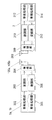
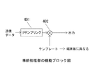
次に、図11と図12を用いて事前処理部302および314の詳細な処理について説明する。まず、送信データはリサンプリング部401に入力される。リサンプリング部401に入力された信号は、図12に示すように、送信データ1ビットの周期がテンプレート1周期の長さまで拡張される。
Next, detailed processing of the preprocessing
すなわち、送信データはNビットとすると、送信データはMビットのビット長に複製されることになる。N、Mの条件は、Nは1以上の整数、Mは2以上の整数、N<Mである。図12の説明では、N=1、M=nの場合を示しているが、N、Mは、上記条件の範囲で任意である。 That is, if the transmission data is N bits, the transmission data is copied to a bit length of M bits. As for the conditions of N and M, N is an integer of 1 or more, M is an integer of 2 or more, and N <M. The description of FIG. 12 shows the case where N = 1 and M = n, but N and M are arbitrary within the range of the above conditions.
図12において、A、B、C、a1、a2、a3は各々1ビット(2値信号)を示す。ここでは、これらは+1または−1の値をとるものとする。テンプレート1周期の長さまで拡張された送信データ1ビットに対して乗算器402でテンプレートと乗算される。
In FIG. 12, A, B, C, a1, a2, and a3 each indicate 1 bit (binary signal). Here, these assume values of +1 or -1.
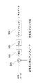
次に、図13と図14を用いて事後処理部305および312の詳細な処理について説明する。まず、受信したデータは乗算器501に入力される。乗算器501に入力された信号は、送信側と同じテンプレートと乗算される。図14に示すように、この乗算出力は、テンプレート1周期の間、積分器502で積分される。そして判定部503において、積分器502の出力が0以上の時には+1を、積分器502の出力が負の時には−1を出力する。そして、図14に示すように、判定部503の出力はビットの周期は、デサンプリング部504において元の周期に戻される(つまりビット長を短縮する)。ここで、乗算器501と積分器502の組み合わせの処理を整合フィルタということもある。
Next, detailed processing of the
事後処理を施された後の単位ビット当たりのエネルギーについて考える。本発明では、図14に示すように、積分出力n・Aの極性(0以上または負)を判定することで、受信データのビットを復調する。従って、伝送路上のノイズなどに起因して伝送誤りが発生しても、積分出力n・Aの極性が反転しなければ、受信データは正しく復調される。このことは、本発明が、その分だけ伝送誤りに耐性を有していることを示している。この場合、積分する長さnが大きい程、積分出力n・Aは大きくなり、伝送誤りへの耐性つまり雑音への耐性が改善されることがわかる。 Consider the energy per unit bit after post-processing. In the present invention, as shown in FIG. 14, the bit of the received data is demodulated by determining the polarity (0 or more or negative) of the integral output n · A. Therefore, even if a transmission error occurs due to noise on the transmission path, the received data is correctly demodulated if the polarity of the integral output n · A is not inverted. This indicates that the present invention is more resistant to transmission errors. In this case, it can be seen that the integral output n · A increases as the integration length n increases, and the resistance to transmission errors, that is, the resistance to noise is improved.
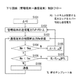
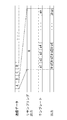
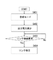
次に、図7と図8を用いて、下り回線の制御処理のフローを説明する。システムが想定する最大通信距離に相当する、管理端末の送信電力をP0とし、管理端末の送信電力の制御幅をΔとする。Δの初期値をゼロとする。ここで、図7のステップS103において、通信端末の整合フィルタ(MF)の出力をRmとする。Rmは受信電力の一例であって、具体的には、積分器502の出力n・Aである。Rmは、ノイズなどの外因を含まない受信電力を意味し、換言すれば、信号成分のみの電力を表している。
Next, the flow of downlink control processing will be described using FIG. 7 and FIG. The transmission power of the management terminal corresponding to the maximum communication distance assumed by the system is P0, and the control width of the transmission power of the management terminal is Δ. The initial value of Δ is set to zero. Here, in step S103 of FIG. 7, the output of the matched filter (MF) of the communication terminal is Rm. Rm is an example of received power, and specifically, is an output n · A of the
次のステップS104においてRmと閾値Tmaを比較する。閾値Tmaは第1の閾値の一例である。Rmが閾値Tmaより大きい場合には、ステップS105において、送信電力の制御幅Δ=Δ−ΔP(ΔP>0)にして、ステップS102に戻り送信電力をΔPだけ小さくする。ステップS104においてRmが閾値Tmaより小さい場合には、次のステップS106に進む。ステップS106において、Rmが閾値Tmiより小さい場合には、ステップS107において、整合フィルタのテンプレート長をΔPTLだけ長くして、ステップS103に戻る。閾値Tmiは第2の閾値の一例である。第2の閾値は第1の閾値より小さい値である、関係にある。 In the next step S104, Rm is compared with the threshold value Tma. The threshold value Tma is an example of a first threshold value. If Rm is greater than the threshold value Tma, in step S105, the transmission power control width Δ = Δ−ΔP (ΔP> 0) is set, and the process returns to step S102 to decrease the transmission power by ΔP. If Rm is smaller than the threshold value Tma in step S104, the process proceeds to the next step S106. If Rm is smaller than the threshold value Tmi in step S106, the template length of the matched filter is increased by ΔPTL in step S107, and the process returns to step S103. The threshold value Tmi is an example of a second threshold value. The second threshold value is a value smaller than the first threshold value.
ステップS107では、送信データを複製するビット長がMビットからKビットに変更される。この場合、K、Mの条件は、Kは1以上の整数、K≠Mである。本実施の形態1では、M=n、K>nの条件であるが、Kは、上記の範囲で任意である。送信データが存在する場合は、リサンプリング部401は、TL+ΔPTLのテンプレート長に対応したビット長まで、送信データを複製する。
In step S107, the bit length for duplicating the transmission data is changed from M bits to K bits. In this case, the condition of K and M is that K is an integer of 1 or more and K ≠ M. In the first embodiment, the conditions are M = n and K> n, but K is arbitrary in the above range. If transmission data exists,
ステップS106において、Rmが閾値Tmiより大きい場合には、通常の通信の処理に進む。図8は、以上の処理フローを時間軸上で示したもので、縦軸は整合フィルタの出力Rmである。 If Rm is larger than the threshold value Tmi in step S106, the process proceeds to normal communication processing. FIG. 8 shows the above processing flow on the time axis, and the vertical axis represents the output Rm of the matched filter.
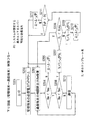
以上の処理においては、送信電力は一方的に減少するだけであり、整合フィルタのテンプレートは一方的に長くなるだけである。もし、移動通信時のように、受信信号レベルが大きく変動するような場合には、度々、フェージングなどによって受信信号レベルが大きく落ち込むことがあるが、その度にテンプレート長を長くすると、通信のオーバーヘッドが非常に大きくなり、リアルタイムでの双方向通信が行えなくなる。図9は、そのような環境でもリアルタイムでの双方向通信が行えることを目的とした下り回線の制御処理のフローである。 In the above processing, the transmission power only decreases unilaterally, and the matched filter template only increases unilaterally. If the received signal level fluctuates significantly as in mobile communication, the received signal level may often drop significantly due to fading, etc. If the template length is increased each time, the communication overhead is increased. Becomes so large that bi-directional communication in real time cannot be performed. FIG. 9 is a flowchart of downlink control processing for the purpose of enabling bidirectional communication in real time even in such an environment.
図9について説明する。システムが想定する最大通信距離に相当する、管理端末の送信電力をP0とし、管理端末の送信電力の制御幅をΔとする。Δの初期値をゼロとする。ここで、図9のステップS203において、通信端末の整合フィルタ(MF)の出力をRmとする。次のステップS204においてRmと閾値Tmaを比較する。Rmが閾値Tmaより大きい場合には、ステップS205において、送信電力の制御幅Δ=Δ−ΔP(ΔP>0)にして、ステップS202に戻り送信電力をΔPだけ小さくする。ステップS204においてRmが閾値Tmaより小さい場合には、次のステップS206に進む。ステップS206において、Rmが閾値Tmiより小さい場合には、ステップS207において、整合フィルタのテンプレート長をΔPTLだけ長くして、ステップS208に進む。ステップS208において、テンプレート長TLと閾値TLmaとを比較する。ステップS208において、テンプレート長TLが閾値TLmaより小さい場合には、ステップS203に戻る。ステップS208において、テンプレート長TLが閾値TLmaより大きい場合には、次のステップS209において、テンプレート長を2ΔPTLだけ小さくなるように設定する。さらに次のステップS210おいて、送信電力をΔPだけ大きくなるように設定する。そして次のステップS211において、送信電力TxPとP0を比較して、送信電力TxPがP0より小さい場合にはステップS202に戻り、送信電力を上げて送信する。ステップS211において、送信電力TxPがP0より大きい場合には、ステップS212において、送信電力をΔPだけ小さくなるように設定して、ステップS202に戻り、結局送信電力を変えることなく、再送信する。ステップS206において、Rmが閾値Tmiより大きい場合には、通常の通信の処理に進む。 FIG. 9 will be described. The transmission power of the management terminal corresponding to the maximum communication distance assumed by the system is P0, and the control width of the transmission power of the management terminal is Δ. The initial value of Δ is set to zero. Here, in step S203 of FIG. 9, the output of the matched filter (MF) of the communication terminal is Rm. In the next step S204, Rm is compared with the threshold value Tma. If Rm is larger than the threshold value Tma, in step S205, the transmission power control width Δ = Δ−ΔP (ΔP> 0) is set, and the process returns to step S202 to decrease the transmission power by ΔP. If Rm is smaller than the threshold value Tma in step S204, the process proceeds to the next step S206. If Rm is smaller than the threshold value Tmi in step S206, the template length of the matched filter is increased by ΔPTL in step S207, and the process proceeds to step S208. In step S208, the template length TL is compared with the threshold value TLma. If the template length TL is smaller than the threshold value TLma in step S208, the process returns to step S203. If the template length TL is larger than the threshold value TLma in step S208, the template length is set to be reduced by 2ΔPTL in the next step S209. Further, in the next step S210, the transmission power is set to increase by ΔP. Then, in the next step S211, the transmission power TxP and P0 are compared. If the transmission power TxP is smaller than P0, the process returns to step S202 to increase the transmission power and transmit. If the transmission power TxP is larger than P0 in step S211, the transmission power is set to be reduced by ΔP in step S212, the process returns to step S202, and re-transmission is performed without changing the transmission power. In step S206, when Rm is larger than the threshold value Tmi, the process proceeds to normal communication processing.
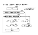
次に、図10を用いて、上り回線の制御処理のフローを説明する。システムが想定する最大通信距離に相当する、通信端末の送信電力をP0とし、通信端末の送信電力の制御幅をΔとする。Δの初期値をゼロとする。ここで、図10のステップS303において、管理端末の整合フィルタ(MF)の出力をRmとする。次のステップS304においてRmと閾値Tmaを比較する。Rmが閾値Tmaより大きい場合には、ステップS305において、送信電力の制御幅Δ=Δ−ΔP(ΔP>0)にして、ステップS302に戻り送信電力をΔPだけ小さくする。ステップS304においてRmが閾値Tmaより小さい場合には、次のステップS306に進む。ステップS306において、Rmが閾値Tmiより小さい場合には、ステップS307において、整合フィルタのテンプレート長をΔPTLだけ長くして、ステップS303に戻る。ステップS306において、Rmが閾値Tmiより大きい場合には、通常の通信の処理に進む。 Next, the flow of uplink control processing will be described with reference to FIG. The transmission power of the communication terminal corresponding to the maximum communication distance assumed by the system is P0, and the control width of the transmission power of the communication terminal is Δ. The initial value of Δ is set to zero. Here, in step S303 in FIG. 10, the output of the matched filter (MF) of the management terminal is set to Rm. In the next step S304, Rm is compared with the threshold value Tma. If Rm is larger than the threshold value Tma, in step S305, the transmission power control width Δ = Δ−ΔP (ΔP> 0) is set, and the process returns to step S302 to decrease the transmission power by ΔP. If Rm is smaller than the threshold value Tma in step S304, the process proceeds to the next step S306. If Rm is smaller than the threshold value Tmi in step S306, the template length of the matched filter is increased by ΔPTL in step S307, and the process returns to step S303. In step S306, if Rm is larger than the threshold value Tmi, the process proceeds to normal communication processing.
次に閾値TmaとTmiについて説明する。受信信号のレベル変動の幅に比べてTmaとTmiの差が小さいと整合フィルタ出力RmがTmaとTmiの間に入る確率が小さくなり、通常の通信の処理時間が短くなり、リアルタイムでの双方向通信が困難になる。そこで、所定の通信時間を確保する必要がある場合には、整合フィルタ出力Rmの変動幅をモニターし、所定の通信時間を確保できるように、整合フィルタ出力RmがTmaとTmiの間に入るようにTmaを設定する。ここで、Tmiは、所定の通信品質の最小値に相当する整合フィルタ出力Rmになるように設定する。 Next, threshold values Tma and Tmi will be described. If the difference between Tma and Tmi is smaller than the width of the level fluctuation of the received signal, the probability that matched filter output Rm falls between Tma and Tmi is reduced, the processing time of normal communication is shortened, and bi-directional in real time Communication becomes difficult. Therefore, when it is necessary to secure a predetermined communication time, the fluctuation range of the matched filter output Rm is monitored so that the matched filter output Rm falls between Tma and Tmi so that the predetermined communication time can be secured. Is set to Tma. Here, Tmi is set to be a matched filter output Rm corresponding to a minimum value of predetermined communication quality.
以上のように、本実施の形態1では、受信電力に応じて送信データを複製するビット長を変更するので、受信電力が変動した場合であっても、セキュリティを確保しながら第三者へのS/N比を上げることなく、正規の受信者へのS/N比のみを向上させることができる。 As described above, in the first embodiment, the bit length for duplicating the transmission data is changed according to the received power, so even if the received power fluctuates, security is ensured to a third party. Without increasing the S / N ratio, only the S / N ratio for a legitimate recipient can be improved.
また、受信電力が所定値より小さい場合に、送信データが複製されるビット長をKビット(M<K)に変更するので、受信電力が低下した場合に、正規の受信者へのS/N比低下を抑制することができる。 In addition, when the received power is smaller than a predetermined value, the bit length for duplicating the transmission data is changed to K bits (M <K). Ratio reduction can be suppressed.
また、送信データの電力を制御する送信電力制御手段を備え、送信電力制御手段は、受信電力が所定値より小さい場合に、送信電力を低下させるので、ビット長を長く変更することなく、送信電力を低下することで、オーバーヘッドの増大を抑制しながら、通信エリアの不要な拡大を防止することができる。 In addition, a transmission power control means for controlling the power of the transmission data is provided, and the transmission power control means reduces the transmission power when the reception power is smaller than a predetermined value, so that the transmission power can be reduced without changing the bit length long. By reducing, it is possible to prevent unnecessary expansion of the communication area while suppressing an increase in overhead.
また、受信電力が第1の閾値より小さい場合に、送信データの電力を低下させ、さらに、受信電力が第1の閾値より小さい第2の閾値より小さい場合に、送信データを複製するビット長を変更するので、受信電力が低下する場合に、送信データの電力を優先した上で、乱数を乗算する送信データの複製範囲を変更するので、通信エリアの不要な拡大を防止した上で、その通信エリア内に存在する正規の受信者へのS/N比低下を抑制することができる。 Further, when the received power is smaller than the first threshold, the power of the transmission data is reduced, and when the received power is smaller than the second threshold smaller than the first threshold, the bit length for duplicating the transmitted data is set. If the received power decreases, the transmission data power is given priority, and the copy range of the transmission data to be multiplied by the random number is changed. It is possible to suppress a decrease in the S / N ratio to a normal recipient existing in the area.
(実施の形態2)
以下、本発明の具体的な内容について実施の形態2を用いて説明する。なお、通信端末1a、1bおよび管理端末2の構成は、実施の形態1における図1ないし図6、図11および図13と共通である。
(Embodiment 2)
Hereinafter, specific contents of the present invention will be described with reference to the second embodiment. Note that the configurations of the
図16は、実施の形態2における鍵生成共有シーケンスを示す図である。図16を用いて全体の処理の概要について説明する。 FIG. 16 is a diagram showing a key generation / sharing sequence according to the second embodiment. An overview of the overall processing will be described with reference to FIG.
ステップS501において、管理端末2と通信端末1a(または通信端末1b)はともに、送信電力制御を行う。この処理は、実施の形態1における図7および図10に示される処理と同じである.これらの処理により、親機と子機が正常に受信可能な最小の送信電力出力となるように、親機と子機の送信電力が制御される一方で、盗聴者が正常に受信出来る領域の広さを最小限に抑える。
In step S501, both the
次に、ステップS502において、通信端末1aで符号化データCDを生成する。符号化データCDを生成するための構成は図11と同じである。符号化データCDは、管理端末2、通信端末1a、1b間で既知のデータである。ここでは、複数ビットで構成され、全てが同じ値である。例えば、オール1(1、1、・・・、1)、オール0(0、0、・・・、0)、オール−1(−1、−1、・・・、−1)。
Next, in step S502, the encoded data CD is generated by the
図6に示す事前処理部302において、リサンプリング部401は、「1」の値からなる送信データ1ビットの周期がテンプレート1周期の長さまで拡張する。ここでは発明の理解を容易にするため、テンプレートの1周期を5ビットとする。従って、リサンプリング部401は、オール1(1、1、1、1、1)で構成される、符号化データCDを出力する。テンプレートが(1、−1、−1、1、1)とすると、乗算器402は、符号化データCDとテンプレートを乗算して、(1、−1、−1、1、1)を出力する。
In the
通信端末1aの変調部303で所定の変調処理を行い、無線部304は、乗算器402の出力値(1、−1、−1、1、1)に基づく送信データを管理端末2に送信する。送信データが空中の伝送媒体を介して伝送されるが、雑音などの周囲の環境によっては送信データに伝送誤りが生じる。ここでは、伝送誤りによって(1、−1、−1、1、1)の2ビット目と4ビット目が誤り、値が反転したとする。その結果、(1、−1、−1、1、1)が(1、1、−1、−1、1)に変化したことになる。
The
ステップ503において、管理端末2は、送信データを受信すると、鍵シーケンスKを生成する。この処理を、図17を用いて説明する。
In
図17は、実施の形態2における鍵シーケンス生成を示すブロック図である。 FIG. 17 is a block diagram illustrating key sequence generation in the second embodiment.
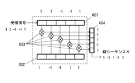
17において、管理端末2の復調部310は、受信された送信データについて復調処理を行い、受信信号(1、1、−1、−1、1)(つまり伝送誤りが生じた乗算器402の出力値)を、事後処理部312に出力する。事後処理部312は、受信信号(1、1、−1、−1、1)を受信信号用シフトレジスタ601に入力する。具体的には、受信信号用シフトレジスタ601に、図17の紙面左から右に掛けて、(1、1、−1、−1、1)が入力される。
17, the
一方、リファレンスシフトレジスタ602には、通信端末1aと同一のテンプレート(1、−1、−1、1、1)が格納されている。図17に示すような対応では、受信信号用シフトレジスタ601とリファレンスシフトレジスタ602の対応する各ビット同士の排他的論理和が、乗算器603で処理される。その結果、各乗算器603の出力は鍵シーケンス格納用シフトレジスタ604の対応するレジスタに格納される。全ての乗算器603の出力が、図17紙面上から下に掛けて、レジスタ604に(1、−1、1、−1、1)が格納され、それらの値は鍵シーケンスKとして出力される。なお、乗算方法は特に排他的論理和に限定されず、他の演算方法でも良い。
On the other hand, the
なお、この場合、仮に、送信データが通信端末1aから管理端末2に伝送される際に、伝送誤りが全く発生していなければ、鍵シーケンスKは、乗算器402の出力値(1、−1、−1、1、1)と一致する。
In this case, if transmission data is not transmitted at all when transmission data is transmitted from the
ステップ504において、鍵シーケンスK(1、−1、1、−1、1)が生成されると、これをもとにして、マスター鍵が生成される。この処理を、図18を用いて説明する。
In
図18は、マスター鍵生成フローを示す図である。 FIG. 18 is a diagram showing a master key generation flow.
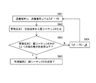
ステップS601において、図16のステップS501で設定された通信端末1aの送信電力が設定される(つまり、通信端末1aの送信信号レベルTxPがP0に設定される)。ステップS602において、管理端末2は、鍵シーケンスKを生成する。ステップS603において、管理端末2は、鍵シーケンスK中の1の数と−1の数の差が所要値以下かどうか判断する。鍵シーケンスKの1の数と−1の数の差が所定値以下でない場合(ステップS603のNo)、ステップS604において、管理端末2は、送信信号レベルTxPをP0からΔだけ減算するように、通信端末1aに指示する。通信端末1aは管理端末2からの指示に従って、送信電力が制御し、送信信号レベルTxPをP0からΔだけ減算する(ステップS601)。
In step S601, the transmission power of
一方、鍵シーケンスKの1の数と−1の数の差が所定値以下の場合(ステップS603のYes)、ステップS605において、管理端末2は、鍵シーケンスKをマスター鍵として出力する。このような鍵シーケンスKを、実際に用いる暗号鍵であるセッション鍵のシードとして使用するので、マスター鍵の推測を困難にすることが出来る。
On the other hand, if the difference between the number of 1s in the key sequence K and the number of -1 is less than or equal to the predetermined value (Yes in step S603), the
本実施の形態で、ステップS603の所定値が「2」とすると、鍵シーケンスKは、(1、−1、1、−1、1)で、1の数と−1の数の差は「1」であるから、鍵シーケンスKは(1、−1、1、−1、1)として生成が完了する。仮に、鍵シーケンスKがオール1となった場合、差は「5」になるので、送信電力を落とすことになる。 In this embodiment, when the predetermined value in step S603 is “2”, the key sequence K is (1, −1, 1, −1, 1), and the difference between the number of 1 and the number of −1 is “ 1 ”, generation of the key sequence K is completed as (1, −1, 1, −1, 1). If the key sequence K is all 1, the difference is “5”, and the transmission power is reduced.
鍵シーケンスKにおける「1」と「−1」の分布に適度なバランスがある場合は、それ自体は鍵シーケンスKとして次の処理を進めるが、鍵シーケンスKにおける値の分布がアンバランスな場合は、送信電力を下げるので、鍵シーケンスKがオール1または−1の分布に遷移して、鍵シーケンスKの分布が適度なバランスとなる。このように、送信電力を制御することで、鍵シーケンスKにおける「1」と「−1」の分布に適度なバランスに設定することが出来るので、鍵シーケンスKを用いた暗号鍵の推測を困難にすることが出来る。 When the distribution of “1” and “−1” in the key sequence K has an appropriate balance, the process proceeds as the key sequence K itself, but when the distribution of values in the key sequence K is unbalanced Since the transmission power is lowered, the key sequence K transitions to the all 1 or -1 distribution, and the distribution of the key sequence K has an appropriate balance. Thus, by controlling the transmission power, the distribution of “1” and “−1” in the key sequence K can be set to an appropriate balance, so it is difficult to guess the encryption key using the key sequence K. Can be made.
次に、管理端末2はマスター鍵を通信端末1aに送信し、管理端末2と通信端末1aでマスター鍵を共有する。共有方法は、暗号化してから送信してもよく、送信電力を落とした近距離通で暗号化することなく送信することも可能である。さらにユーザが手入力で共有されることも可能である。
Next, the
ステップ505において、管理端末2と通信端末1aは、共有したマスター鍵から、実際の暗号化に用いる、同じセッション鍵を生成する。セッション鍵の生成について、図19を用いて説明する。
In
図19は、セッション鍵生成を示す説明図である。 FIG. 19 is an explanatory diagram showing session key generation.
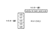
図19において、鍵K1i(i=0、1、2、3、4)は鍵K10をiビット巡回シフトした鍵シーケンスである。H(K1i||K2j)は、K1iとK2jを連結した結果のハッシュ値であり、これをセッション鍵とする。この方法により、長さNの2個のマスター鍵からN2個という非常に多くのセッション鍵を生成することが可能となる。つまり、セッション鍵を頻繁に更新して使うことが容易となり、それだけ安全性の高い鍵共有システムとなる。 In FIG. 19, a key K1i (i = 0, 1, 2, 3, 4) is a key sequence obtained by cyclically shifting the key K10 by i bits. H (K1i || K2j) is a hash value as a result of concatenating K1i and K2j, and this is used as a session key. This method makes it possible to generate a very large number of session keys, N 2, from two master keys of length N. In other words, it becomes easy to update the session key frequently and use it, and the key sharing system with higher security is obtained.
以上のように、実施の形態2では、セッション鍵を生成するのに、予測不可能な物理乱数である、雑音による伝送誤りの情報を利用するので、セッション鍵の予測が困難なものとなり、これを暗号鍵として用いると、安全性の高い暗号システムを構築すること出来る。 As described above, in the second embodiment, the generation of a session key uses information on transmission errors due to noise, which is an unpredictable physical random number, which makes it difficult to predict a session key. If is used as an encryption key, a highly secure encryption system can be constructed.
なお、本実施の形態2では、通信相手の送信電力制御を必要としたが、通信相手の送信電力制御の代わりに、自身の受信系において増幅器の利得制御を行うことでも同様の効果を得ることが出来る。 Although the transmission power control of the communication partner is required in the second embodiment, the same effect can be obtained by controlling the gain of the amplifier in its own reception system instead of the transmission power control of the communication partner. I can do it.
また、本実施の形態では、通信相手の符号化データを用いたが、受信信号電力が所要値以上で、ある程度の通信品質が確保されている時に、符号化データ受信以降の処理を行えば、同様の効果を得ることが出来る。 Further, in the present embodiment, the encoded data of the communication partner is used, but when the received signal power is equal to or higher than the required value and a certain level of communication quality is ensured, if processing after reception of the encoded data is performed, Similar effects can be obtained.
以上のような代替の方法を用いれば、通信相手の実装内容に関わらず、自身の実装のみで、前記の非常に高い安全性を有する暗号システムを構築出来る。 If such an alternative method is used, the above-described cryptographic system having extremely high security can be constructed only by its own implementation regardless of the contents of implementation of the communication partner.
なお、上記実施の形態1、2は、無線通信について説明したが、有線通信であっても良い。例えば、イーサネット(登録商標)、PLC(電力線通信)、電話線、同軸ケーブルを用いた通信媒体など各種を利用することが出来る。 In the first and second embodiments, the wireless communication has been described. However, wired communication may be used. For example, various types such as a communication medium using Ethernet (registered trademark), PLC (power line communication), a telephone line, and a coaxial cable can be used.
本発明の通信装置、通信システムおよび通信方法は、不正アクセスや盗聴への耐性を有するとともに、高い伝送信頼性を確保するため、伝送路が第3者にも共用されている他、劣悪である無線や電力線を使った通信に適用出来る。 The communication device, the communication system, and the communication method of the present invention are inferior in addition to having a resistance to unauthorized access and eavesdropping and ensuring a high transmission reliability in addition to sharing the transmission path with a third party. It can be applied to communication using wireless or power lines.
1a 通信端末
1b 通信端末
2 管理端末
302 通信端末の事前処理部
303 通信端末の変調部
304 通信端末の無線部
305 通信端末の事後処理部
306 通信端末の復調部
308 管理端末のアンテナ
309 管理端末の無線部
310 管理端末の復調部
312 管理端末の事後処理部
313 管理端末の変調部
314 管理端末の事前処理部
401 事前処理部のリサンプリング部
402 事前処理部の乗算器
501 事後処理部の乗算器
502 事後処理部の積分器
503 事後処理部の判定部
504 事後処理部のデサンプリング部
601 受信信号用シフトレジスタ
602 リファレンスシフトレジスタ
603 乗算器
604 鍵シーケンス格納用シフトレジスタ
DESCRIPTION OF
Claims (10)
Nビットの送信データをMビットのビット長に複製する複製手段と(Nは1以上の整数、Mは2以上の整数、N<M)、
前記複製手段により複製された送信データに乱数を乗算する乗算手段と、
前記乗算手段により乱数が乗算された送信データを前記他の通信装置に送信する送信手段とを備え、
前記複製手段は、前記他の通信装置からの受信電力に応じて、送信データを複製するビット長をMビットからKビットに変更し(Kは1以上の整数、K≠M)、Nビットの送信データをKビットのビット長に複製することを特徴とする通信装置。 A communication device that communicates with other communication devices,
Duplicating means for duplicating N-bit transmission data to M-bit bit length (N is an integer of 1 or more, M is an integer of 2 or more, N <M),
Multiplication means for multiplying the transmission data duplicated by the duplication means by a random number;
Transmission means for transmitting transmission data multiplied by a random number by the multiplication means to the other communication device,
The duplicating means changes the bit length for duplicating transmission data from M bits to K bits according to the received power from the other communication device (K is an integer of 1 or more, K ≠ M), and N bits A communication apparatus for duplicating transmission data to a bit length of K bits.
前記送信電力制御手段は、前記受信電力が所定値より小さい場合に、送信電力を低下させることを特徴とする請求項2記載の通信装置。 Furthermore, a transmission power control means for controlling the power of transmission data is provided,
The communication apparatus according to claim 2, wherein the transmission power control means reduces the transmission power when the received power is smaller than a predetermined value.
前記複製手段は、前記受信電力が前記第1の閾値より小さい第2の閾値より小さい場合に、送信データを複製するビット長を変更することを特徴とする請求項3記載の通信装置。 The transmission power control means reduces the power of transmission data when the reception power is smaller than a first threshold,
4. The communication apparatus according to claim 3, wherein the duplicating unit changes a bit length for duplicating transmission data when the received power is smaller than a second threshold smaller than the first threshold.
前記乗算手段は、さらに、前記受信データに乱数を乗算し、
前記複製手段は、さらに、前記乱数が乗算された受信データのビット長をMビットからNビットに短縮し、
前記複製手段は、前記受信データの電力に応じて、前記送信データを複製するビット長とともに、前記受信データに乗算される乱数のビット長をMビットからKビットに変更することを特徴とする請求項1記載の通信装置。 And further comprising receiving means for receiving M-bit received data from the other communication device,
The multiplication means further multiplies the received data by a random number,
The duplicating means further reduces the bit length of the received data multiplied by the random number from M bits to N bits,
The duplicating means changes a bit length of a random number to be multiplied by the received data from M bits to K bits together with a bit length for duplicating the transmitted data according to the power of the received data. Item 2. The communication device according to Item 1.
Nビットの送信データをMビットのビット長に複製し(Nは1以上の整数、Mは2以上の整数、N<M)、
前記複製された送信データに乱数を乗算し、
前記乱数が乗算された送信データを前記他の通信装置に送信し、
前記送信データを複製する場合において、前記他の通信装置からの受信電力に応じて、送信データを複製するビット長をMビットからKビットに変更し(Kは1以上の整数、K≠M)、Nビットの送信データをKビットのビット長に複製することを特徴とする通信方法。 A communication method for communicating with other communication devices,
N bits of transmission data are copied to an M bit length (N is an integer of 1 or more, M is an integer of 2 or more, N <M),
Multiplying the duplicated transmission data by a random number;
Transmitting the transmission data multiplied by the random number to the other communication device;
When duplicating the transmission data, the bit length for duplicating the transmission data is changed from M bits to K bits according to the received power from the other communication device (K is an integer of 1 or more, K ≠ M) A communication method, wherein N-bit transmission data is copied to a bit length of K bits.
前記送信装置は、
Nビットの送信データをMビットのビット長に複製する複製手段と(Nは1以上の整数、Mは2以上の整数、N<M)、
前記複製手段により複製された送信データに乱数を乗算する第1の乗算手段と、
前記第1の乗算手段により乱数が乗算された送信データを前記受信装置に送信する送信手段とを備え、
前記複製手段は、前記受信電力に応じて、送信データを複製するビット長をMビットからKビットに変更し(Kは1以上の整数、K≠M)、Nビットの送信データをKビットのビット長に複製し、
前記受信装置は、
前記送信装置からMビットの受信データを受信する受信手段と、
前記受信データに乱数を乗算する第2の乗算手段と、
前記乱数が乗算された受信データのビット長をMビットからNビットに短縮する短縮手段とを備え、
前記短縮手段は、前記受信電力に応じて、前記送信データを複製するビット長とともに、前記受信データに乗算される乱数のビット長をMビットからKビットに変更し、Kビットの送信データをNビットのビット長に短縮することを特徴とする通信システム。 A communication system having a transmitter and a receiver,
The transmitter is
Duplicating means for duplicating N-bit transmission data to M-bit bit length (N is an integer of 1 or more, M is an integer of 2 or more, N <M),
First multiplication means for multiplying the transmission data duplicated by the duplication means by a random number;
Transmission means for transmitting transmission data multiplied by a random number by the first multiplication means to the reception device;
The duplication means changes the bit length for duplicating the transmission data from M bits to K bits according to the received power (K is an integer of 1 or more, K ≠ M), and N bits of transmission data are converted to K bits. Duplicate to bit length,
The receiving device is:
Receiving means for receiving M-bit received data from the transmitting device;
Second multiplication means for multiplying the received data by a random number;
Shortening means for shortening the bit length of the received data multiplied by the random number from M bits to N bits,
The shortening means changes the bit length of the random number multiplied to the received data from M bits to K bits together with the bit length for duplicating the transmitted data according to the received power, and converts the K-bit transmitted data to N bits. A communication system characterized in that the bit length is shortened to a bit length.
前記マスター鍵生成手段は、さらに、前記受信データにおいて前記第1の値のビット数と前記第2の値のビット数の差が所定値以下の場合に、前記乱数が乗算された受信データを鍵シーケンスとしてマスター鍵を生成することを特徴とする請求項9記載の通信システム。 The received data includes a binary value of a first value and a second value;
The master key generation means further uses the received data multiplied by the random number as a key when the difference between the number of bits of the first value and the number of bits of the second value is less than or equal to a predetermined value in the received data. The communication system according to claim 9, wherein a master key is generated as a sequence.
Priority Applications (1)
| Application Number | Priority Date | Filing Date | Title |
|---|---|---|---|
| JP2012055568A JP2012217153A (en) | 2011-03-31 | 2012-03-13 | Communication device, communication system, and communication method |
Applications Claiming Priority (3)
| Application Number | Priority Date | Filing Date | Title |
|---|---|---|---|
| JP2011077631 | 2011-03-31 | ||
| JP2011077631 | 2011-03-31 | ||
| JP2012055568A JP2012217153A (en) | 2011-03-31 | 2012-03-13 | Communication device, communication system, and communication method |
Publications (1)
| Publication Number | Publication Date |
|---|---|
| JP2012217153A true JP2012217153A (en) | 2012-11-08 |
Family
ID=47269467
Family Applications (1)
| Application Number | Title | Priority Date | Filing Date |
|---|---|---|---|
| JP2012055568A Pending JP2012217153A (en) | 2011-03-31 | 2012-03-13 | Communication device, communication system, and communication method |
Country Status (1)
| Country | Link |
|---|---|
| JP (1) | JP2012217153A (en) |
-
2012
- 2012-03-13 JP JP2012055568A patent/JP2012217153A/en active Pending
Similar Documents
| Publication | Publication Date | Title |
|---|---|---|
| CN110691356B (en) | Ultra-wideband safety distance measurement | |
| CN102342139B (en) | Apparatus and method for virtual pairing using existing wireless connection key | |
| CN105681233B (en) | Orthogonal differential vector signaling | |
| US20190380018A1 (en) | Method and device for identifying bluetooth headset voice source | |
| US8522029B2 (en) | Secret-key exchange for wireless and sensor networks | |
| US20110093712A1 (en) | Communication device supporting pairing | |
| KR101410764B1 (en) | Apparatus and method for remotely deleting important information | |
| CN102057650A (en) | Method and apparatus for verifying data packet integrity in a streaming data channel | |
| US10635619B2 (en) | Encoding for multi-device synchronization of devices | |
| CN106211301B (en) | A method for realizing physical layer security and power optimization in a full-duplex communication system | |
| WO2015100890A1 (en) | Near field communication proximity detection method and apparatus | |
| TWI493888B (en) | Extension of ethernet phy to channels with bridged tap wires | |
| JP5789054B2 (en) | Data encoding apparatus and method based on difference of complex amplitude | |
| AU2006321928B2 (en) | Method and apparatus for authenticating a mobile phone accessory | |
| WO2013088174A1 (en) | Data transfer | |
| CN105681256B (en) | Audio communication method and voice communication application apparatus | |
| US20140181938A1 (en) | Packet processor verification methods and systems | |
| JP2012217153A (en) | Communication device, communication system, and communication method | |
| WO2013075484A1 (en) | Method and device for detecting interference | |
| CN112104444B (en) | Reference signal sending method, terminal and network side device | |
| CN103874074B (en) | Signal processing method and device thereof | |
| CN100413231C (en) | bluetooth connector | |
| JP5323106B2 (en) | Signal restoration apparatus and method | |
| CN107484246B (en) | Resource allocation method, system and storage medium based on cooperative interference | |
| TW200427296A (en) | Data control cable for connecting a mobile device to a host device |