JP2012215117A5 - - Google Patents
Download PDFInfo
- Publication number
- JP2012215117A5 JP2012215117A5 JP2011080662A JP2011080662A JP2012215117A5 JP 2012215117 A5 JP2012215117 A5 JP 2012215117A5 JP 2011080662 A JP2011080662 A JP 2011080662A JP 2011080662 A JP2011080662 A JP 2011080662A JP 2012215117 A5 JP2012215117 A5 JP 2012215117A5
- Authority
- JP
- Japan
- Prior art keywords
- engine
- frames
- pump
- frame
- pair
- Prior art date
- Legal status (The legal status is an assumption and is not a legal conclusion. Google has not performed a legal analysis and makes no representation as to the accuracy of the status listed.)
- Granted
Links
Images
Description
本発明の第1の特徴によれば、ポンプケースの下部に設けられたドレン排出孔から排出されるドレンを、エンジン本体の一部を構成するエンジン構成体にその側壁の外面から突出するようにして一体に設けられるエンジン側リブで下方に導くので、ドレン排水路を複数のカバー部材で構成することが不要であり、カバー部材の形状の自由度を増大することができるとともにカバー部材の大型化を避けることができ、冷却水ポンプから排出されるドレンを導く排水路構造の簡素化を図ることができる。 According to a first aspect of the present invention, the drain discharged from the drain discharge hole provided in the lower portion of the pump casing, so as to project from the outer surface of the side wall to the engine structure constituting a part of the engine body Therefore, it is unnecessary to configure the drain drainage channel with a plurality of cover members, increasing the degree of freedom of the shape of the cover member and increasing the size of the cover member. Therefore, it is possible to simplify the drainage channel structure that guides the drain discharged from the cooling water pump.
本発明の実施の形態について添付の図1〜図7を参照しながら説明すると、先ず図1において、自動二輪車の車体フレームFは、前輪WFを軸支したフロントフォーク51を操向可能に支承するヘッドパイプ52と、該ヘッドパイプ52から後下がりに延びる左右一対のメインフレーム53…と、それらのメインフレーム53…よりも急傾斜で後下がりに延びる左右一対のダウンフレーム54…と、前記メインフレーム53…の後端から下方に延びる左右一対のセンターフレーム55…と、該センターフレーム55…の上部から後上がりに延びる左右一対のシートレール56…と、前記センターフレーム55…の中間部および前記シートレール56…の後部間を結ぶリヤフレーム57…とを備える。 The embodiment of the present invention will be described with reference to FIGS. 1 to 7 attached herewith. First, in FIG. 1, a body frame F of a motorcycle supports a front fork 51 that pivotally supports a front wheel WF so as to be steerable. The head pipe 52, a pair of left and right main frames 53 extending rearward and downward from the head pipe 52, a pair of left and right down frames 54 extending rearward and lower than the main frames 53, and the main frame 53... A pair of left and right center frames 55 extending downward from the rear end, a pair of left and right seat rails 56 extending rearward from the upper part of the center frame 5 5 , and an intermediate portion of the center frame 55. And rear frames 57 connecting the rear portions of the seat rails 56.
図2を併せて参照して、前記メインフレーム53…、ダウンフレーム54…およびセンターフレーム55…で囲まれる領域には、多気筒たとえば2気筒であるエンジンのエンジン本体11が搭載されており、エンジンと、エンジン本体11に一部が内蔵される変速機(図示せず)とを備えるパワーユニットPが車体フレームFで支持されるようにして配置され、該パワーユニットPが発揮する動力で駆動される後輪WRを後端部で軸支するスイングアーム58の前端部が、前記センターフレーム55…に上下揺動可能に支承される。また前記エンジン本体11の上方でメインフレーム53…に収納ボックス59が搭載され、該収納ボックス59の後方にタンデム型の乗車用シート60が前記シートレール56…で支持されるようにして配置され、乗車用シート60の下方に燃料タンク61が配置される。 Referring also to FIG. 2, the main frame 53 ..., in the region surrounded by the down frames 54 ... and the center frames 55 ..., and the engine main body 11 of the engine is mounted is a multi-cylinder example 2-cylinder engine And a power unit P including a transmission (not shown) partially incorporated in the engine body 11 is disposed so as to be supported by the vehicle body frame F, and is driven by the power exerted by the power unit P. The front end portion of the swing arm 58 that pivotally supports the wheel WR at the rear end portion is supported on the center frame 55 so as to be vertically swingable. Further, a storage box 59 is mounted on the main frame 53 above the engine body 11, and a tandem riding seat 60 is disposed behind the storage box 59 so as to be supported by the seat rails 56, A fuel tank 61 is disposed below the riding seat 60.
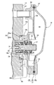
前記インペラ22は前記ポンプ室23内で前記ポンプ軸21に固定されており、このポンプ室23の中央部に通じる吸入室34が前記ポンプカバー20および前記プレート19間に形成される。
The
また第1のエンジン側リブ43は、前記シリンダヘッド14の左側の側壁14aの下部外面に突設されるボルト締結用のボス46に一体に連なって形成されており、このボス46は、ポンプケース17をシリンダヘッド14に締結するための3つのボルト36…の1つを締結するためのものである。
The first engine side rib 43, the is formed by integrally connected to the boss 46 of the bolt fastening is projected on the lower outer surface of the
Priority Applications (5)
| Application Number | Priority Date | Filing Date | Title |
|---|---|---|---|
| JP2011080662A JP5703097B2 (en) | 2011-03-31 | 2011-03-31 | Drainage structure from cooling water pump in vehicle engine |
| ITTO20120214 ITTO20120214A1 (en) | 2011-03-31 | 2012-03-09 | STRUCTURE FOR DRAINING WATER FROM A WATER-COOLING PUMP INTO THE ENGINE OF A VEHICLE. |
| DE102012204884.7A DE102012204884B4 (en) | 2011-03-31 | 2012-03-27 | Structure for discharging water from a cooling water pump in a vehicle engine |
| US13/432,848 US9010283B2 (en) | 2011-03-31 | 2012-03-28 | Structure for discharging water from cooling water pump in vehicle engine |
| BRBR102012007604-7A BR102012007604A2 (en) | 2011-03-31 | 2012-03-28 | VEHICLE ENGINE COOLING WATER PUMP WATER FRAMEWORK |
Applications Claiming Priority (1)
| Application Number | Priority Date | Filing Date | Title |
|---|---|---|---|
| JP2011080662A JP5703097B2 (en) | 2011-03-31 | 2011-03-31 | Drainage structure from cooling water pump in vehicle engine |
Publications (3)
| Publication Number | Publication Date |
|---|---|
| JP2012215117A JP2012215117A (en) | 2012-11-08 |
| JP2012215117A5 true JP2012215117A5 (en) | 2014-02-27 |
| JP5703097B2 JP5703097B2 (en) | 2015-04-15 |
Family
ID=46833083
Family Applications (1)
| Application Number | Title | Priority Date | Filing Date |
|---|---|---|---|
| JP2011080662A Active JP5703097B2 (en) | 2011-03-31 | 2011-03-31 | Drainage structure from cooling water pump in vehicle engine |
Country Status (5)
| Country | Link |
|---|---|
| US (1) | US9010283B2 (en) |
| JP (1) | JP5703097B2 (en) |
| BR (1) | BR102012007604A2 (en) |
| DE (1) | DE102012204884B4 (en) |
| IT (1) | ITTO20120214A1 (en) |
Families Citing this family (2)
| Publication number | Priority date | Publication date | Assignee | Title |
|---|---|---|---|---|
| CN204200337U (en) * | 2013-07-03 | 2015-03-11 | 福特环球技术公司 | Liquid cooling explosive motor |
| JP7195203B2 (en) | 2019-03-29 | 2022-12-23 | 本田技研工業株式会社 | internal combustion engine |
Family Cites Families (16)
| Publication number | Priority date | Publication date | Assignee | Title |
|---|---|---|---|---|
| JPH0356899U (en) * | 1989-10-05 | 1991-05-31 | ||
| JPH04116297A (en) | 1990-09-06 | 1992-04-16 | Yamaha Motor Co Ltd | Cooling water pump fitting structure for engine |
| JPH04103290U (en) * | 1991-01-22 | 1992-09-07 | イーグル工業株式会社 | water pump |
| JP2542589Y2 (en) * | 1991-05-27 | 1997-07-30 | 愛三工業株式会社 | Water pump |
| DE4119131A1 (en) | 1991-06-11 | 1992-12-17 | Kloeckner Humboldt Deutz Ag | Casing for rotary pump - has leakage channel set into swirl vane to drain off fluid |
| GB9124446D0 (en) | 1991-11-18 | 1992-01-08 | Hobourn Eng Ltd | Rotary assemblies |
| JP3173222B2 (en) | 1993-04-16 | 2001-06-04 | スズキ株式会社 | Water pump |
| US5338153A (en) | 1993-06-30 | 1994-08-16 | Caterpillar Inc. | Non-drip fluid circulating pump |
| JP2797918B2 (en) * | 1993-09-20 | 1998-09-17 | 日産自動車株式会社 | Water pump for internal combustion engine |
| JPH11257041A (en) * | 1998-03-05 | 1999-09-21 | Komatsu Zenoah Co | Cam chamber for portable 4-cycle engine |
| JP3456903B2 (en) | 1998-09-14 | 2003-10-14 | 本田技研工業株式会社 | Internal combustion engine for motorcycles |
| JP3558164B2 (en) | 2000-10-05 | 2004-08-25 | 本田技研工業株式会社 | Water pump |
| JP3867841B2 (en) | 2001-10-26 | 2007-01-17 | 本田技研工業株式会社 | V-type internal combustion engine for motorcycles |
| JP4087273B2 (en) | 2003-03-31 | 2008-05-21 | 株式会社山田製作所 | water pump |
| JP4248363B2 (en) * | 2003-10-14 | 2009-04-02 | 株式会社クボタ | engine |
| JP4933463B2 (en) * | 2008-02-14 | 2012-05-16 | 本田技研工業株式会社 | Single cylinder 4-stroke internal combustion engine |
-
2011
- 2011-03-31 JP JP2011080662A patent/JP5703097B2/en active Active
-
2012
- 2012-03-09 IT ITTO20120214 patent/ITTO20120214A1/en unknown
- 2012-03-27 DE DE102012204884.7A patent/DE102012204884B4/en active Active
- 2012-03-28 US US13/432,848 patent/US9010283B2/en active Active
- 2012-03-28 BR BRBR102012007604-7A patent/BR102012007604A2/en not_active Application Discontinuation
Similar Documents
| Publication | Publication Date | Title |
|---|---|---|
| JP5129712B2 (en) | Radiator mounting structure for motorcycles | |
| TWI417215B (en) | Motorcycle | |
| JP3157145U (en) | Motorcycle | |
| JP3154590U (en) | Motorcycle | |
| JP2016088160A (en) | Fuel cell two-wheeled vehicle | |
| JP2010058758A (en) | Saddle riding type four-wheeled vehicle | |
| JP3157144U (en) | Motorcycle | |
| JP2012215117A5 (en) | ||
| JP5700832B2 (en) | Scooter type vehicle | |
| JP5719264B2 (en) | Canister layout for saddle riding type vehicles | |
| JP2014065469A (en) | Battery arrangement structure for hybrid vehicle | |
| JP4211778B2 (en) | Motorcycle fuel supply system | |
| JP6034430B2 (en) | Radiator arrangement structure for saddle riding type vehicle | |
| JP5703097B2 (en) | Drainage structure from cooling water pump in vehicle engine | |
| CA2769876A1 (en) | Evaporated fuel treatment device for motorcycle | |
| JP2007062611A (en) | Motorcycle | |
| JP2015067247A (en) | Saddle-riding type vehicle | |
| JP2013136343A (en) | Motorcycle | |
| JP6256017B2 (en) | Cooling structure for belt transmission | |
| JP2012111417A (en) | Motorcycle | |
| TWI254007B (en) | Motorcycle | |
| JP5928042B2 (en) | Air cleaner for motorcycle | |
| JP2011256756A (en) | Fuel supply device of vehicle | |
| WO2019117239A1 (en) | Straddle-type vehicle | |
| JP2013019383A (en) | Scooter type motorcycle |