JP2012209510A - Optical fiber laser light source - Google Patents
Optical fiber laser light source Download PDFInfo
- Publication number
- JP2012209510A JP2012209510A JP2011075601A JP2011075601A JP2012209510A JP 2012209510 A JP2012209510 A JP 2012209510A JP 2011075601 A JP2011075601 A JP 2011075601A JP 2011075601 A JP2011075601 A JP 2011075601A JP 2012209510 A JP2012209510 A JP 2012209510A
- Authority
- JP
- Japan
- Prior art keywords
- light source
- output
- laser light
- optical waveguide
- fiber laser
- Prior art date
- Legal status (The legal status is an assumption and is not a legal conclusion. Google has not performed a legal analysis and makes no representation as to the accuracy of the status listed.)
- Withdrawn
Links
Images


Abstract
Description
本発明は、光ファイバレーザ光源に関し、さらに詳しくは、出力安定性が高い光ファイバレーザ光源に関する。 The present invention relates to an optical fiber laser light source, and more particularly to an optical fiber laser light source having high output stability.
従来、半導体レーザと、半導体レーザが出力する励起レーザ光を導波する励起光導波路と、励起光導波路から出力される励起レーザ光によって励起され所定の帯域を有する自然放出光を出力する増幅媒体を添加した増幅光導波路と、増幅光導波路から出力される自然放出光を導波する出力光導波路と、増幅光導波路と出力光導波路の間に設けられ所定の帯域の光を選択的に透過する波長選択素子と、増幅光導波路が出力する自然放出光を波長選択素子に透過させるレンズを有する空間結合部と、励起光導波路と増幅光導波路の間に設けられた入射側反射手段と、空間結合部と出力光導波路の間に設けられた出力側反射手段とを備えた光源が知られている(例えば、特許文献1,2参照。)。
Conventionally, there are provided a semiconductor laser, a pumping optical waveguide that guides pumping laser light output from the semiconductor laser, and an amplification medium that outputs spontaneous emission light having a predetermined band excited by pumping laser light output from the pumping optical waveguide. Added optical waveguide, output optical waveguide that guides spontaneous emission light output from the amplification optical waveguide, and wavelength that is provided between the amplification optical waveguide and the output optical waveguide and selectively transmits light in a predetermined band A spatial coupling unit having a selection element, a lens that transmits the spontaneous emission light output from the amplification optical waveguide to the wavelength selection element, an incident-side reflection unit provided between the excitation optical waveguide and the amplification optical waveguide, and a spatial coupling unit And a light source including output side reflection means provided between the output optical waveguides are known (see, for example,
上記従来の光源では、空間結合部におけるレンズや波長選択素子の端面において光の反射がある。すなわち、光の反射点が複数箇所となる。このため、出力安定性に問題がある。
そこで、本発明は、出力安定性が高い光ファイバレーザ光源を提供することを目的とする。
In the conventional light source, there is light reflection at the end face of the lens or wavelength selection element in the spatial coupling portion. That is, there are a plurality of light reflection points. For this reason, there is a problem in output stability.
Therefore, an object of the present invention is to provide an optical fiber laser light source having high output stability.
第1の観点では、本発明は、[イ]半導体励起レーザ(1)が出力する励起光を導波する励起光導波ファイバ(2)と、[ロ] 前記励起光導波ファイバ(2)から出力される励起光を入力して所定の波長帯域の放出光を放出すると共に光を導波する増幅光導波ファイバ(3)と、[ハ]前記増幅光導波ファイバ(3)から出力される光を導波する出力光導波ファイバ(4)と、[ニ]前記励起光導波ファイバ(2)の出力側端面に設けられ且つ前記増幅光導波ファイバ(3)の入力側端面との間に入力側空隙(N)を形成するか、又は、前記増幅光導波ファイバ(3)の入力側端面に設けられ且つ前記励起光導波ファイバ(2)の出力側端面との間に入力側空隙(N)を形成し、所定の波長帯域の光を反射し且つ所定の波長帯域の光を透過する入力側フィルタ膜(7)と、[ホ]前記出力光導波ファイバ(4)の入力側端面に設けられ且つ前記増幅光導波ファイバ(3)の出力側端面との間に出力側空隙(S)を形成するか、又は、前記増幅光導波ファイバ(3)の出力側端面に設けられ且つ前記出力光導波ファイバ(4)の入力側端面との間に出力側空隙(S)を形成し、所定の波長帯域の光を反射し且つ所定の波長帯域の光を透過し、前記入力側フィルタ膜(7)との間で第1光共振器(K1)を構成する出力側ハーフミラー膜(8)と、[へ]前記出力光導波路ファイバ(4)の内部に設けられ、前記入力側フィルタ膜(7)との間で第2光共振器(K2)を構成するファイバブラッググレーティング(14)とを具備し、[ト]前記入力側空隙(N)の距離(Ln)および前記出力側空隙(S)の距離(Ls)が20μm以下であることを特徴とする光ファイバレーザ光源(100)を提供する。
上記第1の観点による光ファイバレーザ光源(100)では、入力側フィルタ膜(7)での入力側空隙(N)と出力側ハーフミラー膜(8)での出力側空隙(S)の2カ所しか空間部がなく且つ入力側フィルタ膜(7)と出力側ハーフミラー膜(8)の間で第1光共振器(K1)を構成する。また、入力側フィルタ膜(7)とファイバブラッググレーティング(14)の間で第2光共振器(K2)を構成し、2段階複合共振器構造とする。これらにより、出力安定性が高くなる。さらに、入力側空隙(N)の距離(Ln)および出力側空隙(S)の距離(Ls)を20μm以下としたため、共振波長間隔30nm以上になり、モードホップが起こりにくくなり、この点でも出力安定性が高くなる。
In the first aspect, the present invention provides [a] a pumping light waveguide fiber (2) for guiding pumping light output from the semiconductor pumping laser (1), and [b] output from the pumping light waveguide fiber (2). And amplifying optical waveguide fiber (3) for emitting emitted light of a predetermined wavelength band and guiding the light, and [c] light output from the amplifying optical waveguide fiber (3). An input-side gap is provided between the output optical waveguide fiber (4) to be guided and [d] the output-side end face of the pumping-light waveguide fiber (2) and the input-side end face of the amplification optical waveguide fiber (3). (N) or an input side gap (N) provided on the input side end face of the amplification optical waveguide fiber (3) and between the output side end face of the excitation light waveguide fiber (2) And reflects light of a predetermined wavelength band and transmits light of a predetermined wavelength band. Between the input side filter membrane (7) and [e] the input side end face of the output optical waveguide fiber (4) and the output side end face (S Or an output side air gap (S) provided between the output side end face of the amplified optical waveguide fiber (3) and the input side end face of the output optical waveguide fiber (4), An output-side half mirror film (8) that reflects light of a predetermined wavelength band and transmits light of a predetermined wavelength band and constitutes the first optical resonator (K1) with the input-side filter film (7). And [to] a fiber Bragg grating (14) provided in the output optical waveguide fiber (4) and constituting a second optical resonator (K2) between the input filter film (7) and [G] Distance (Ln) of the input side gap (N) and Distance serial output gap (S) (Ls) to provide an optical fiber laser source (100), characterized in that at 20μm or less.
In the optical fiber laser light source (100) according to the first aspect, the input side gap (N) in the input side filter film (7) and the output side gap (S) in the output side half mirror film (8) are two places. However, the first optical resonator (K1) is formed between the input side filter film (7) and the output side half mirror film (8). Further, the second optical resonator (K2) is formed between the input side filter film (7) and the fiber Bragg grating (14) to form a two-stage composite resonator structure. As a result, the output stability is increased. Furthermore, since the distance (Ln) of the input side gap (N) and the distance (Ls) of the output side gap (S) are 20 μm or less, the resonance wavelength interval is 30 nm or more, and mode hops are less likely to occur. Increases stability.
第2の観点では、本発明は、前記第1の観点による光ファイバレーザ光源(100)において、前記増幅光導波路ファイバ(3)は、増幅媒体として希土類元素が添加されたコア(3a)と、前記コア(3a)の外側に設けた該コア(3a)より屈折率が低い内部クラッド(3b)と、前記内部クラッド(3b)の外側に設けた該内部クラッド(3b)より屈折率が低い外部クラッド(3c)とを有することを特徴とする光ファイバレーザ光源(100)を提供する。
上記第2の観点による光ファイバレーザ光源(100)では、コア(3a)および内部クラッド(3b)が半導体レーザからの励起光を導波し、コア(3a)に添加した増幅媒体が励起光で励起されて放出光を発生し、その放出光はコア(3a)を導波する。
In a second aspect, the present invention provides the optical fiber laser light source (100) according to the first aspect, wherein the amplification optical waveguide fiber (3) includes a core (3a) to which a rare earth element is added as an amplification medium; An inner cladding (3b) having a lower refractive index than the core (3a) provided outside the core (3a), and an outer having a lower refractive index than the inner cladding (3b) provided outside the inner cladding (3b) An optical fiber laser light source (100) characterized by having a clad (3c) is provided.
In the optical fiber laser light source (100) according to the second aspect, the core (3a) and the inner cladding (3b) guide the pumping light from the semiconductor laser, and the amplification medium added to the core (3a) is the pumping light. It is excited to generate emission light, and the emission light is guided through the core (3a).
第3の観点では、本発明は、前記第1または第2の観点による光ファイバレーザ光源(100)において、前記増幅光導波ファイバ(3)の長さ(L3)が、前記所定の波長帯域の放出光が放出されるように調整されていることを特徴とする光ファイバレーザ光源(100)を提供する。
増幅光導波ファイバ(3)の放出光の波長帯域は、増幅光導波ファイバ(3)の長さ(L3)に応じて変化する。
そこで、上記第3の観点による光ファイバレーザ光源(100)では、増幅光導波ファイバ(3)の長さ(L3)を調整し、所定の波長帯域の放出光が放出されるようにする。
In a third aspect, the present invention provides the optical fiber laser light source (100) according to the first or second aspect, wherein the length (L3) of the amplified optical waveguide fiber (3) is in the predetermined wavelength band. Provided is an optical fiber laser light source (100) characterized in that it is adjusted to emit emitted light.
The wavelength band of the emitted light of the amplified optical waveguide fiber (3) changes according to the length (L3) of the amplified optical waveguide fiber (3).
Therefore, in the optical fiber laser light source (100) according to the third aspect, the length (L3) of the amplified optical waveguide fiber (3) is adjusted so that emitted light in a predetermined wavelength band is emitted.
第4の観点では、本発明は、前記第1から第3のいずれかの観点による光ファイバレーザ光源(100)において、前記入力側フィルタ膜(7)は、前記励起光に対して透過率95%以上で且つ前記放出光に対して反射率95%以上であることを特徴とする光ファイバレーザ光源(100)を提供する。
上記第4の観点による光ファイバレーザ光源(100)では、励起光を効率よく増幅光導波ファイバ(3)に入力し、増幅光導波ファイバ(3)で発生した放出光を効率よく反射させることが出来る。
In a fourth aspect, the present invention provides the optical fiber laser light source (100) according to any one of the first to third aspects, wherein the input side filter film (7) has a transmittance of 95 with respect to the excitation light. An optical fiber laser light source (100) having a reflectance of 95% or more with respect to the emitted light is provided.
In the optical fiber laser light source (100) according to the fourth aspect, the excitation light is efficiently input to the amplified optical waveguide fiber (3), and the emitted light generated by the amplified optical waveguide fiber (3) is efficiently reflected. I can do it.
第5の観点では、本発明は、前記第1から第4のいずれかの観点による光ファイバレーザ光源(100)において、前記出力側ハーフミラー膜(8)は、前記放出光に対して反射率4%〜90%であることを特徴とする光ファイバレーザ光源(100)を提供する。
第1光共振器(K1)の出力スペクトルは、出力側ハーフミラー膜(8)の反射率に応じて変化する。
そこで、上記第5の観点による光ファイバレーザ光源(100)では、出力側ハーフミラー膜(8)の反射率を4%〜90%の間で調整し、所定の波長帯域の出力光が得られるようにする。
In a fifth aspect, the present invention provides the optical fiber laser light source (100) according to any one of the first to fourth aspects, wherein the output-side half mirror film (8) has a reflectance with respect to the emitted light. An optical fiber laser light source (100) characterized by being 4% to 90% is provided.
The output spectrum of the first optical resonator (K1) changes according to the reflectance of the output-side half mirror film (8).
Therefore, in the optical fiber laser light source (100) according to the fifth aspect, the reflectance of the output-side half mirror film (8) is adjusted between 4% and 90% to obtain output light in a predetermined wavelength band. Like that.
第6の観点では、本発明は、 前記第1から第5のいずれかの観点による光ファイバレーザ光源(100)において、前記増幅光導波ファイバ(3)のコア(3a)と前記出力光導波路ファイバ(4)のコア(4a)の中心軸をずらせたことを特徴とする光ファイバレーザ光源(100)を提供する。
光ファイバレーザ光源の性質として、半導体励起レーザ(1)のパワーが低いと、増幅光導波ファイバ(3)に励起されていない(反転分布が不安定)状態の部分が生じ、出力が不安定となり、ノイズも多くなる。例えば、蛍光分析を行う顕微鏡装置などではノイズ(rms)は数%程度以下を要求されるが、半導体励起レーザ(1)のパワーが低いとこの要求を満たせない。このため、半導体励起レーザ(1)のパワーを上げてやらなければならない。しかし、半導体励起レーザ(1)のパワーを上げると出力光のパワーも大きくなってしまい、例えば出力光が入力されるSHG素子の寿命を短くしてしまうなどの問題を生じる。
そこで、上記第6の観点による光ファイバレーザ光源(100)では、増幅光導波ファイバ(3)のコア(3a)と出力光導波路ファイバ(4)のコア(4a)の中心軸をずらせて、出力光のパワーを減衰させる。これにより、半導体励起レーザ(1)のパワーを上げて出力を安定させることが出来ると共に出力光のパワーが強くなり過ぎることを防止できる。
In a sixth aspect, the present invention provides an optical fiber laser light source (100) according to any one of the first to fifth aspects, wherein the core (3a) of the amplified optical waveguide fiber (3) and the output optical waveguide fiber An optical fiber laser light source (100) characterized in that the center axis of the core (4a) of (4) is shifted.
As a property of the optical fiber laser light source, if the power of the semiconductor pump laser (1) is low, the amplified optical waveguide fiber (3) is not pumped (inversion distribution is unstable), and the output becomes unstable. , Noise increases. For example, in a microscope apparatus that performs fluorescence analysis, noise (rms) is required to be about several percent or less, but this requirement cannot be satisfied if the power of the semiconductor excitation laser (1) is low. For this reason, the power of the semiconductor pump laser (1) must be increased. However, if the power of the semiconductor pump laser (1) is increased, the power of the output light also increases, causing problems such as shortening the life of the SHG element to which the output light is input.
Therefore, in the optical fiber laser light source (100) according to the sixth aspect, the center axes of the core (3a) of the amplified optical waveguide fiber (3) and the core (4a) of the output optical waveguide fiber (4) are shifted to output Attenuates the power of light. As a result, the power of the semiconductor pump laser (1) can be increased to stabilize the output, and the power of the output light can be prevented from becoming too strong.
第7の観点では、本発明は、 前記第1から第6のいずれかの観点による光ファイバレーザ光源(100)において、前記出力光導波路ファイバ(4)の1カ所で切断し且つ軸ずらし融着したこと特徴とする光ファイバレーザ光源(100)を提供する。
光ファイバレーザ光源の性質として、半導体励起レーザ(1)のパワーが低いと、増幅光導波ファイバ(3)に励起されていない(反転分布が不安定)状態の部分が生じ、出力が不安定となり、ノイズも多くなる。例えば、蛍光分析を行う顕微鏡装置などではノイズ(rms)は2%程度以下を要求されるが、半導体励起レーザ(1)のパワーが低いとこの要求を満たせない。このため、半導体励起レーザ(1)のパワーを上げてやらなければならない。しかし、半導体励起レーザ(1)のパワーを上げると出力光のパワーも大きくなってしまい、例えば出力光が入力されるSHG素子の寿命を短くしてしまうなどの問題を生じる。
そこで、上記第7の観点による光ファイバレーザ光源(100)では、出力光導波路ファイバ(4)の1カ所で切断し且つ軸ずらし融着して、出力光のパワーを減衰させる。これにより、半導体励起レーザ(1)のパワーを上げて出力を安定させることが出来ると共に出力光のパワーが強くなり過ぎることを防止できる。
In a seventh aspect, the present invention relates to the optical fiber laser light source (100) according to any one of the first to sixth aspects, wherein the output optical waveguide fiber (4) is cut at one place and is off-axis fused. An optical fiber laser light source (100) is provided.
As a property of the optical fiber laser light source, if the power of the semiconductor pump laser (1) is low, the amplified optical waveguide fiber (3) is not pumped (inversion distribution is unstable), and the output becomes unstable. , Noise increases. For example, in a microscope apparatus that performs fluorescence analysis, noise (rms) is required to be about 2% or less, but this requirement cannot be satisfied if the power of the semiconductor excitation laser (1) is low. For this reason, the power of the semiconductor pump laser (1) must be increased. However, if the power of the semiconductor pump laser (1) is increased, the power of the output light also increases, causing problems such as shortening the life of the SHG element to which the output light is input.
Therefore, in the optical fiber laser light source (100) according to the seventh aspect, the power of the output light is attenuated by cutting at one point of the output optical waveguide fiber (4) and fusing it while shifting its axis. As a result, the power of the semiconductor pump laser (1) can be increased to stabilize the output, and the power of the output light can be prevented from becoming too strong.
第8の観点では、本発明は、前記第1から第7のいずれかの観点による光ファイバレーザ光源(100)において、前記出力側ハーフミラー膜(8)と前記ファイバブラッググレーティング(14)の間に、偏光分離手段(13)を具備することを特徴とする光ファイバレーザ光源(100)を提供する。
上記第8の観点による光ファイバレーザ光源(100)では、第2光共振器(K2)内に偏光分離手段(13)を設置することにより、直線偏波出力が可能となるので、直線偏波成分のみを波長変換するSHG素子への光源として好適となる。
In an eighth aspect, the present invention relates to an optical fiber laser light source (100) according to any one of the first to seventh aspects, wherein the output side half mirror film (8) and the fiber Bragg grating (14) are arranged. And an optical fiber laser light source (100), characterized in that it comprises polarization separation means (13).
In the optical fiber laser light source (100) according to the eighth aspect, linearly polarized wave output can be performed by installing the polarization separating means (13) in the second optical resonator (K2). It is suitable as a light source for an SHG element that converts the wavelength of only the component.
第9の観点では、本発明は、前記第8の観点による光ファイバレーザ光源(100)において、前記偏光分離手段(13)が、偏波保持光ファイバ溶融カプラ型の偏光分離素子(13)からなることを特徴とする光ファイバレーザ光源(100)を提供する。
上記第9の観点による光ファイバレーザ光源(100)では、偏波保持光ファイバ溶融カプラ型の偏光分離素子(13)を使用したので、偏光子を挟むような偏光分離手段と比較して、空間伝播部がなく、内部反射点に起因する出力光のノイズ増大の影響を受けない。
In a ninth aspect, the present invention provides the optical fiber laser light source (100) according to the eighth aspect, wherein the polarization separation means (13) is a polarization maintaining optical fiber fusion coupler type polarization separation element (13). An optical fiber laser light source (100) is provided.
In the optical fiber laser light source (100) according to the ninth aspect, since the polarization maintaining optical fiber fusion coupler type polarization separation element (13) is used, the space is smaller than the polarization separation means that sandwiches the polarizer. There is no propagation part, and it is not affected by the noise increase of the output light caused by the internal reflection point.
第10の観点では、本発明は、前記第1から第9のいずれかの観点による光ファイバレーザ光源(100)において、前記増幅光導波ファイバ(3)および前記出力光導波ファイバ(4)が、偏波保持型光ファイバであることを特徴とする光ファイバレーザ光源(100)を提供する。
上記第10の観点による光ファイバレーザ光源(100)では、直線偏波出力を行うことが出来るので、直線偏波成分のみを波長変換するSHG素子への光源として好適となる。
In a tenth aspect, the present invention provides the optical fiber laser light source (100) according to any one of the first to ninth aspects, wherein the amplified optical waveguide fiber (3) and the output optical waveguide fiber (4) are: An optical fiber laser light source (100) is provided that is a polarization maintaining optical fiber.
The optical fiber laser light source (100) according to the tenth aspect is suitable as a light source for an SHG element that converts the wavelength of only the linearly polarized wave component because it can perform linearly polarized wave output.
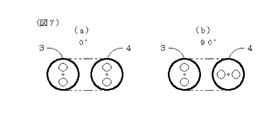
第11の観点では、本発明は、前記第10の観点による光ファイバレーザ光源(100)において、前記増幅光導波ファイバ(3)と前記出力光導波ファイバ(4)の偏波軸同士が0°または90°であることを特徴とする光ファイバレーザ光源(100)を提供する。
増幅光導波ファイバ(3)と出力光導波ファイバ(4)の偏波軸同士が0°または90°でないと、第2光共振器(K2)内を往復する光の直線偏波が保持されなくなる。
そこで、上記第11の観点による光ファイバレーザ光源(100)では、増幅光導波ファイバ(3)と出力光導波ファイバ(4)の偏波軸同士を0°または90°に調整する。
In an eleventh aspect, the present invention provides the optical fiber laser light source (100) according to the tenth aspect, wherein the polarization axes of the amplified optical waveguide fiber (3) and the output optical waveguide fiber (4) are 0 °. Alternatively, an optical fiber laser light source (100) characterized by being 90 ° is provided.
If the polarization axes of the amplification optical waveguide fiber (3) and the output optical waveguide fiber (4) are not 0 ° or 90 °, the linear polarization of the light reciprocating in the second optical resonator (K2) cannot be maintained. .
Therefore, in the optical fiber laser light source (100) according to the eleventh aspect, the polarization axes of the amplified optical waveguide fiber (3) and the output optical waveguide fiber (4) are adjusted to 0 ° or 90 °.
第12の観点では、本発明は、前記第1から第11のいずれかの観点による光ファイバレーザ光源(100)において、前記励起光導波ファイバ(2)の出力側端面または前記増幅光導波ファイバ(3)の入力側端面のうちの前記入力側フィルタ膜(7)が設けられていない方に反射防止膜(17)が設けられていることを特徴とする光ファイバレーザ光源(100)を提供する。
励起光導波ファイバ(2)の出力側端面または増幅光導波ファイバ(3)の入力側端面のうちの入力側フィルタ膜(7)が設けられていない方の面に反射防止膜(17)を設けない場合、該面での反射に起因してモードホップ発生し、発振波長が変動することがある。
上記第12の観点による光ファイバレーザ光源(100)では、反射防止膜(17)を設けているため、モードホップが起こらず、発振波長の変動を抑制できる。
In a twelfth aspect, the present invention provides an optical fiber laser light source (100) according to any one of the first to eleventh aspects, wherein an output side end face of the pumping optical waveguide fiber (2) or the amplified optical waveguide fiber ( An optical fiber laser light source (100) is provided, wherein an antireflection film (17) is provided on the input side end face of (3) where the input side filter film (7) is not provided. .
An antireflection film (17) is provided on the surface of the output side end face of the pumping optical waveguide fiber (2) or the input side end face of the amplification optical waveguide fiber (3) where the input side filter film (7) is not provided. If not, mode hops occur due to reflection on the surface, and the oscillation wavelength may fluctuate.
In the optical fiber laser light source (100) according to the twelfth aspect, since the antireflection film (17) is provided, mode hops do not occur and fluctuations in the oscillation wavelength can be suppressed.
第13の観点では、本発明は、前記第1から第12のいずれかの観点による光ファイバレーザ光源(100)において、前記増幅光導波ファイバ(3)の出力側端面または前記出力光導波路ファイバ(4)の入力側端面のうちの前記出力側ハーフミラー膜(8)が設けられていない方に反射防止膜(18)が設けられていることを特徴とする光ファイバレーザ光源(100)を提供する。
増幅光導波ファイバ(3)の出力側端面または出力光導波ファイバ(4)の入力側端面のうちの出力側ハーフミラー膜(8)が設けられていない方の面に反射防止膜(18)を設けない場合、該面での反射に起因してモードホップ発生し、発振波長が変動することがある。
上記第13の観点による光ファイバレーザ光源(100)では、反射防止膜(18)を設けているため、モードホップが起こらず、発振波長の変動を抑制できる。
In a thirteenth aspect, the present invention provides an optical fiber laser light source (100) according to any one of the first to twelfth aspects, wherein an output side end face of the amplified optical waveguide fiber (3) or the output optical waveguide fiber ( An optical fiber laser light source (100) is provided, wherein an antireflection film (18) is provided on the input side end face of 4) on which the output side half mirror film (8) is not provided. To do.
An antireflection film (18) is provided on the output side end face of the amplified optical waveguide fiber (3) or the input side end face of the output optical waveguide fiber (4) on which the output side half mirror film (8) is not provided. If not provided, mode hops may occur due to reflection on the surface, and the oscillation wavelength may vary.
In the optical fiber laser light source (100) according to the thirteenth aspect, since the antireflection film (18) is provided, mode hops do not occur and fluctuations in the oscillation wavelength can be suppressed.
第14の観点では、本発明は、前記第1から前記第13のいずれかの観点による光ファイバレーザ光源(100)において、前記励起光導波ファイバ(2)の出力側端部がフェルール(31)に固定されており、前記増幅光導波ファイバ(3)の入力側端部がフェルール(32)に固定されており、前記増幅光導波ファイバ(3)の出力側端部がフェルール(33)に固定されており、前記出力光導波ファイバ(4)の入力側端部がフェルール(34)に固定されていることを特徴とする光ファイバレーザ光源(100)を提供する。
上記第14の観点による光ファイバレーザ光源(100)では、フェルール(31)により励起光導波ファイバ(2)の出力側端部の取り扱いが容易になる。また、フェルール(32)により増幅光導波ファイバ(3)の入力側端部の取り扱いが容易になる。また、フェルール(33)により増幅光導波ファイバ(3)の出力側端部の取り扱いが容易になる。また、フェルール(34)により出力光導波ファイバ(4)の入力側端部の取り扱いが容易になる。
In a fourteenth aspect, the present invention provides the optical fiber laser light source (100) according to any one of the first to thirteenth aspects, wherein the output side end of the pumping optical waveguide fiber (2) has a ferrule (31). The input side end of the amplified optical waveguide fiber (3) is fixed to the ferrule (32), and the output side end of the amplified optical waveguide fiber (3) is fixed to the ferrule (33). An optical fiber laser light source (100) is provided, wherein an input side end of the output optical waveguide fiber (4) is fixed to a ferrule (34).
In the optical fiber laser light source (100) according to the fourteenth aspect, the ferrule (31) facilitates handling of the output side end of the pumping light waveguide fiber (2). Further, the ferrule (32) facilitates handling of the input side end of the amplified optical waveguide fiber (3). Further, the ferrule (33) facilitates handling of the output side end of the amplified optical waveguide fiber (3). Further, the ferrule (34) facilitates handling of the input side end of the output optical waveguide fiber (4).
第15の観点では、本発明は、前記第14の観点による光ファイバレーザ光源(100)において、前記フェルール(31〜34)が、セラミックスまたは透明ガラスからなることを特徴とする光ファイバレーザ光源(100)を提供する。
上記第15の観点による光ファイバレーザ光源(100)では、セラミックスの場合、光コネクタに使用されているジルコニアをそのまま流用できる利点がある。透明ガラスの場合、紫外線を良く透過させられるので、ファイバ(2,3,4)とフェルール(31,32,33,34)の接合に紫外線硬化型接着剤を使用できる利点がある。
In a fifteenth aspect, the present invention provides the optical fiber laser light source (100) according to the fourteenth aspect, wherein the ferrules (31 to 34) are made of ceramics or transparent glass. 100).
In the case of ceramics, the optical fiber laser light source (100) according to the fifteenth aspect has an advantage that zirconia used in an optical connector can be used as it is. In the case of transparent glass, since ultraviolet rays can be transmitted well, there is an advantage that an ultraviolet curable adhesive can be used for joining the fibers (2, 3, 4) and the ferrules (31, 32, 33, 34).
第16の観点では、本発明は、前記第14または前記第15の観点による光ファイバレーザ光源(100)において、前記増幅光導波路ファイバ(3)が、増幅媒体として希土類元素が添加されたコア(3a)と、前記コア(3a)の外側に設けた該コア(3a)より屈折率が低い内部クラッド(3b)と、前記内部クラッド(3b)の外側に設けた該内部クラッド(3b)より屈折率が低い外部クラッド(3c)とを有する場合に、前記増幅光導波ファイバ(3)の出力側端部の前記フェルール(33)に挿入する部分の前記外部クラッド(3c)を除去し、前記内部クラッド(3b)と同じかそれよりも高い屈折率の接着剤(35)により前記フェルール(33)の挿入穴と前記内部クラッド(3b)の間を充填し固めたことを特徴とする光ファイバレーザ光源(100)を提供する。
上記第16の観点による光ファイバレーザ光源(100)では、増幅光導波ファイバ(3)の出力側端部の外部クラッド(3c)を除去し、内部クラッド(3b)と同じかそれよりも高い屈折率の接着剤(35)でフェルール(33)の挿入穴と内部クラッド(3b)の間を充填し固めるため、内部クラッド(3b)を伝播してきた残留励起光を効率よく外部に漏れ出させることが出来る。従って、増幅光導波ファイバ(3)の出力側端部とフェルール(33)の接合部分に残留励起光で熱がこもることを抑制できる。なお、熱がこもると、接合部分の劣化が早まる。また、熱膨張により接合状態が変動し、出力特性が劣化する。
According to a sixteenth aspect, the present invention relates to the optical fiber laser light source (100) according to the fourteenth or fifteenth aspect, wherein the amplification optical waveguide fiber (3) is a core doped with a rare earth element as an amplification medium ( 3a), an inner cladding (3b) having a refractive index lower than that of the core (3a) provided outside the core (3a), and an inner cladding (3b) provided outside the inner cladding (3b). When the outer cladding (3c) having a low rate is included, the outer cladding (3c) in the portion inserted into the ferrule (33) at the output side end of the amplified optical waveguide fiber (3) is removed, and the inner cladding The gap between the insertion hole of the ferrule (33) and the inner cladding (3b) is filled and hardened with an adhesive (35) having a refractive index equal to or higher than that of the cladding (3b). Providing an optical fiber laser source (100).
In the optical fiber laser light source (100) according to the sixteenth aspect, the outer cladding (3c) at the output side end of the amplified optical waveguide fiber (3) is removed, and the refraction is equal to or higher than that of the inner cladding (3b). In order to fill and harden the space between the insertion hole of the ferrule (33) and the inner cladding (3b) with an adhesive (35) with a high rate, the residual excitation light propagating through the inner cladding (3b) can be efficiently leaked to the outside. I can do it. Therefore, it is possible to suppress heat from being accumulated by the residual excitation light at the junction between the output side end of the amplified optical waveguide fiber (3) and the ferrule (33). In addition, when heat accumulates, deterioration of a junction part will be accelerated. In addition, the joining state varies due to thermal expansion, and the output characteristics deteriorate.
第17の観点では、本発明は、前記第16の観点による光ファイバレーザ光源(100)において、前記フェルール(34)が透明ガラスからなる場合に、前記出力光導波ファイバ(4)の入力側端部を挿入する前記フェルール(34)のファイバ挿入口が円錐形状に加工されると共に金メッキまたは銀メッキ(36)がなされていることを特徴とする光ファイバレーザ光源(100)を提供する。
上記第17の観点による光ファイバレーザ光源(100)では、増幅光導波ファイバ(3)から漏れ出す残留励起光(および前記第6の観点による軸ずらし接続を行った際に損失となった光)を金メッキまたは銀メッキ(36)で外部へ反射・散乱させることが出来る。これにより、残留励起光(および前記第6の観点による軸ずらし接続を行った際に損失となった光)がフェルール(34)の接着剤溜りの部分に入射し発熱させることを防止でき、信頼性の向上が図れる。
In a seventeenth aspect, the present invention relates to an input side end of the output optical waveguide fiber (4) when the ferrule (34) is made of transparent glass in the optical fiber laser light source (100) according to the sixteenth aspect. An optical fiber laser light source (100) is provided in which a fiber insertion port of the ferrule (34) for inserting a portion is processed into a conical shape and is plated with gold or silver (36).
In the optical fiber laser light source (100) according to the seventeenth aspect, residual pumping light leaking out from the amplification optical waveguide fiber (3) (and light lost when the off-axis connection according to the sixth aspect is performed) Can be reflected and scattered to the outside by gold plating or silver plating (36). This prevents the residual excitation light (and the light lost when the off-axis connection according to the sixth aspect is performed) from entering the adhesive reservoir portion of the ferrule (34) and generating heat. Can improve the performance.
第18の観点では、本発明は、前記第14から前記第17のいずれかの観点による光ファイバレーザ光源(100)において、前記フェルール(31)の出力側端面と前記フェルール(32)の入力側端面の少なくとも一方に円環状の溝(27)を設け、前記フェルール(31)の出力側端面と前記フェルール(32)の入力側端面の前記溝(27)より外側の部分を接着剤(37)で接着し、前記フェルール(33)の出力側端面と前記フェルール(34)の入力側端面の少なくとも一方に円環状の溝(28)を設け、前記フェルール(33)の出力側端面と前記フェルール(34)の入力側端面の前記溝(28)より外側の部分を接着剤(38)で接着したことを特徴とする光ファイバレーザ光源(100)を提供する。
上記第18の観点による光ファイバレーザ光源(100)では、接着剤(37)が光路に入り込むことを溝(27)で防止することが出来る。また、接着剤(38)が光路に入り込むことを溝(28)で防止することが出来る。
In an eighteenth aspect, the present invention provides the optical fiber laser light source (100) according to any one of the fourteenth to seventeenth aspects, wherein an output side end face of the ferrule (31) and an input side of the ferrule (32) An annular groove (27) is provided in at least one of the end faces, and an adhesive (37) is provided between the output side end face of the ferrule (31) and the input end face of the ferrule (32) outside the groove (27). And an annular groove (28) is provided in at least one of the output side end face of the ferrule (33) and the input side end face of the ferrule (34), and the output side end face of the ferrule (33) and the ferrule ( 34) An optical fiber laser light source (100) characterized in that a portion of the input side end face outside the groove (28) is bonded with an adhesive (38).
In the optical fiber laser light source (100) according to the eighteenth aspect, the groove (27) can prevent the adhesive (37) from entering the optical path. Further, the groove (28) can prevent the adhesive (38) from entering the optical path.
第19の観点では、本発明は、前記第14から前記第18のいずれかの観点による光ファイバレーザ光源(100)において、前記フェルール(31)および前記フェルール(32)を同径の円筒状とし、両者をスリーブ(41)で保持し、前記フェルール(33)および前記フェルール(34)を同径の円筒状とし、両者をスリーブ(42)で保持したことを特徴とする光ファイバレーザ光源(100)を提供する。
上記第19の観点による光ファイバレーザ光源(100)では、励起光導波ファイバ(2)の出力側端部と増幅光導波ファイバ(3)の結合部をスリーブ(41)によって保護することが出来る。また、増幅光導波ファイバ(3)の出力側端部と出力光導波ファイバ(4)の結合部をスリーブ(42)によって保護することが出来る。なお、熱伝導性・熱容量が大きいスリーブを用いれば、結合損失による熱や残留励起光の漏れ出しによる熱を結合部から効率的に放熱させることが出来る。
In a nineteenth aspect, the present invention provides the optical fiber laser light source (100) according to any one of the fourteenth to eighteenth aspects, wherein the ferrule (31) and the ferrule (32) are cylindrical with the same diameter. Both are held by a sleeve (41), the ferrule (33) and the ferrule (34) are cylindrical with the same diameter, and both are held by a sleeve (42). )I will provide a.
In the optical fiber laser light source (100) according to the nineteenth aspect, the coupling portion between the output side end portion of the pumping light waveguide fiber (2) and the amplification light waveguide fiber (3) can be protected by the sleeve (41). Further, the coupling portion between the output side end portion of the amplified optical waveguide fiber (3) and the output optical waveguide fiber (4) can be protected by the sleeve (42). If a sleeve having a large thermal conductivity and heat capacity is used, heat due to coupling loss and heat due to leakage of residual excitation light can be efficiently radiated from the coupling portion.
第20の観点では、本発明は、前記第1から前記第19のいずれかの観点による光ファイバレーザ光源(100)において、前記増幅光導波ファイバ(3)と前記出力光導波ファイバ(4)の結合部に温調手段(10)を設けたことを特徴とする光ファイバレーザ光源(100)を提供する。
上記第20の観点による光ファイバレーザ光源(100)では、結合損失による熱や残留励起光の漏れ出しによる熱を温調手段(10)で吸収することが出来る。また、結合部の温度を制御することで、出力側空隙(S)の距離(Ls)を制御できる。なお、出力側空隙(S)の距離(Ls)が変化すると、出力特性(波長,パワー,ノイズ)が変化する。
In a twentieth aspect, the present invention provides an optical fiber laser light source (100) according to any one of the first to nineteenth aspects, wherein the amplified optical waveguide fiber (3) and the output optical waveguide fiber (4) Provided is an optical fiber laser light source (100) characterized in that a temperature control means (10) is provided at a coupling portion.
In the optical fiber laser light source (100) according to the twentieth aspect, heat due to coupling loss and heat due to leakage of residual excitation light can be absorbed by the temperature adjusting means (10). Further, the distance (Ls) of the output side gap (S) can be controlled by controlling the temperature of the coupling portion. Note that when the distance (Ls) of the output-side gap (S) changes, the output characteristics (wavelength, power, noise) change.
第21の観点では、本発明は、前記第1から前記第20のいずれかの観点による光ファイバレーザ光源(100)において、前記増幅光導波ファイバ(3)の温調手段(50)を設けたことを特徴とする光ファイバレーザ光源(100)を提供する。
上記第21の観点による光ファイバレーザ光源(100)では、増幅光導波ファイバ(3)の温度を制御することで、発振波長を制御できる。すなわち、増幅光導波ファイバ(3)を加熱することで発振波長を長波長側にシフトし、増幅光導波ファイバ(3)を冷却することで発振波長を短波長側にシフトすることが出来る。
In a twenty-first aspect, the present invention is the optical fiber laser light source (100) according to any one of the first to twentieth aspects, wherein temperature control means (50) for the amplified optical waveguide fiber (3) is provided. An optical fiber laser light source (100) is provided.
In the optical fiber laser light source (100) according to the twenty-first aspect, the oscillation wavelength can be controlled by controlling the temperature of the amplified optical waveguide fiber (3). That is, the oscillation wavelength can be shifted to the longer wavelength side by heating the amplified optical waveguide fiber (3), and the oscillation wavelength can be shifted to the shorter wavelength side by cooling the amplified optical waveguide fiber (3).
本発明の光ファイバレーザ光源(100)によれば、出力安定性を向上することが出来る。 According to the optical fiber laser light source (100) of the present invention, output stability can be improved.
以下、図に示す実施の形態により本発明をさらに詳細に説明する。なお、これにより本発明が限定されるものではない。 Hereinafter, the present invention will be described in more detail with reference to embodiments shown in the drawings. Note that the present invention is not limited thereby.
−実施例1−
図1は、実施例1に係る光ファイバレーザ光源100の構成説明図である。
この光ファイバレーザ光源100は、次の構成要素を備えている。
[イ]マルチモード光ファイバであり、半導体励起レーザ1が出力する励起光を導波する励起光導波ファイバ2、
[ロ]偏波保持型光ファイバであり、励起光導波ファイバ2から出力される励起光を入力して所定の波長帯域の放出光を放出すると共に光を導波する増幅光導波ファイバ3、
[ハ]偏波保持型光ファイバであり、増幅光導波ファイバ3から出力される光を導波する出力光導波ファイバ4、
[ニ]励起光導波ファイバ2の出力側端面に設けられ且つ増幅光導波ファイバ3の入力側端面との間に入力側空隙Nを形成し、所定の波長帯域の光を反射し且つ所定の波長帯域の光を透過する入力側フィルタ膜7、
[ホ]増幅光導波ファイバ3の出力側端面に設けられ且つ出力光導波ファイバ4の入力側端面との間に出力側空隙Sを形成し、所定の波長帯域の光を反射し且つ所定の波長帯域の光を透過し、入力側フィルタ膜7との間で第1光共振器K1を構成する出力側ハーフミラー膜8、
[へ]出力光導波路ファイバ4の内部に設けられ、入力側フィルタ膜7との間で第2光共振器K2を構成するファイバブラッググレーティング14、
[ト]入力側空隙Nの距離Lnおよび出力側空隙Sの距離Lsが20μm以下である、
[チ]ファイバブラッググレーティング14より前段の出力光導波路ファイバ4の途中に設けられた偏波保持光ファイバ溶融カプラ型の偏光分離素子13、
[リ]増幅光導波ファイバ3と出力光導波ファイバ4の結合部を温調する温調器10、
[ヌ]増幅光導波ファイバ3を温調する温調器50、
[ル]出力光導波ファイバ4から出力される出力光の一部を分岐するビームスプリッタ21、
[ヲ]ビームスプリッタ21で分岐された出力光を受光する受光素子22,
[ワ]受光素子22で出力光を監視し、半導体励起レーザ1を帰還制御する制御部23。
Example 1
FIG. 1 is an explanatory diagram of a configuration of an optical fiber
The optical fiber
[A] pumping
[B] Amplification
[C] Polarization-maintaining optical fiber, an output
[D] An input-side air gap N is formed between the input-side end surface of the amplifying
[E] An output side air gap S is formed between the output side end face of the amplified
[F] A fiber Bragg grating 14 provided in the output
[G] The distance Ln of the input side gap N and the distance Ls of the output side gap S are 20 μm or less.
[H] Polarization-maintaining optical fiber fusion coupler type
[Li] a
[Nu]
[Le] a
[W] a
[W] A
なお、[ニ]の入力側フィルタ膜7の代わりに、増幅光導波ファイバ3の入力側端面に設けられ且つ励起光導波ファイバ2の出力側端面との間に入力側空隙Nを形成し、所定の波長帯域の光を反射し且つ所定の波長帯域の光を透過する入力側フィルタ膜を用いてもよい。
Instead of the input
また、[ホ]の出力側ハーフミラー膜8の代わりに、出力光導波ファイバ4の入力側端面に設けられ且つ増幅光導波ファイバ3の出力側端面との間に出力側空隙Sを形成し、所定の波長帯域の光を反射し且つ所定の波長帯域の光を透過し、入力側フィルタ膜との間で第1光共振器K1を構成する出力側ハーフミラー膜を用いてもよい。
Further, instead of the output side
図2は、光ファイバレーザ光源100を含む光ファイバレーザ光源200の構成説明図である。
この光ファイバレーザ光源200は、光ファイバレーザ光源100の構成要素[イ]〜[ヌ]および次の構成要素を備えている。
[カ]出力光導波ファイバ4から出力される出力光の高調波光を出力するSHG素子51、
[ヨ]SHG素子51から出力される出力光の一部を分岐するビームスプリッタ21、
[タ]ビームスプリッタ21で分岐された出力光を受光する受光素子22,
[レ]受光素子22で出力光を監視し、半導体励起レーザ1を帰還制御する制御部23。
FIG. 2 is an explanatory diagram of a configuration of an optical fiber
The optical fiber
[F] SHG element 51 for outputting harmonic light of output light output from output
[Y] a
[T] A
[L] A
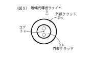
図3は、増幅光導波ファイバ3の断面図である。
増幅光導波路ファイバ3は、増幅媒体として希土類元素が添加されたコア3aと、コア3aの外側に設けた該コア3aより屈折率が低い内部クラッド(石英クラッド)3bと、内部クラッド3bの外側に設けた該内部クラッド3bより屈折率が低い外部クラッド(樹脂クラッド)3cとを有するダブルクラッドYbファイバである。
FIG. 3 is a cross-sectional view of the amplified
The amplification
図4は、増幅光導波ファイバ3のパラメータを示す図表である。
増幅光導波ファイバ3の長さL3は、例えば1〜15mである。
増幅媒体として添加された希土類元素は、例えばイッテルビウムのイオンであり、波長915nmの励起光により励起され、1000nm〜1200nmの波長帯域の放出光を発生する。
FIG. 4 is a chart showing parameters of the amplified
The length L3 of the amplified
The rare earth element added as the amplifying medium is, for example, ytterbium ions, and is excited by excitation light having a wavelength of 915 nm to generate emission light having a wavelength band of 1000 nm to 1200 nm.
出力光導波ファイバ4は、980PANDAファイバである。
The output
図5は、励起光導波ファイバ2と増幅光導波ファイバ3の結合部の拡大断面図である。
励起光導波ファイバ2の出力側端部は、樹脂被覆が除去され、円筒状のフェルール31に挿入され、クラッドの外周面がフェルール31に例えばUV硬化樹脂で接着されている。
フェルール31は、セラミックスまたは透明ガラスからなる。
FIG. 5 is an enlarged cross-sectional view of a coupling portion between the excitation
A resin coating is removed from the output side end of the excitation
The ferrule 31 is made of ceramics or transparent glass.
入力側フィルタ膜7は、励起光導波ファイバ2の出力側端部をフェルール31に挿入した後、フェルール31ごと励起光導波ファイバ2の出力側端面を研磨し、その研磨面に誘電体多層膜を形成して設けられる。
入力側フィルタ膜7は、励起光に対して透過率95%以上で且つ放出光に対して反射率95%以上である。例えば波長915nmに対しては透過率95%以上で且つ波長900nm〜1200nmに対して反射率95%以上である。
The input
The input
増幅光導波ファイバ3の入力側端部は、円筒状のフェルール32に挿入され、外周面がフェルール32に例えばUV硬化樹脂で接着されている。
フェルール32は、セラミックスまたは透明ガラスからなる。
フェルール32の入力側端面には、円環状に溝27が形成されている。
The input side end of the amplification
The
An annular groove 27 is formed on the input side end face of the
増幅光導波ファイバ3の入力側端部をフェルール32に挿入した後、フェルール32ごと増幅光導波ファイバ3の入力側端面を研磨し、その研磨面の溝27より内側に反射防止膜17が設けられる。反射防止膜17は、例えば波長950nm〜1150nmに応じたARコートである。
After the input side end of the amplified
励起光導波ファイバ2の出力側端部を挿入したフェルール31は、金属製のスリーブ41の中程までスリーブ41に挿入される。
他方、増幅光導波ファイバ3の入力側端部を挿入したフェルール32は、溝27より外側の入力側端面に接着剤37を塗布され、スリーブ41に挿入され、フェルール31に接着される。
The ferrule 31 into which the output side end portion of the excitation
On the other hand, the
図6は、増幅光導波ファイバ3と出力光導波ファイバ4の結合部の拡大断面図である。
増幅光導波ファイバ3の出力側端部は、外部クラッド3cが除去され、円筒状のフェルール33に挿入され、内部クラッド3bの外周面がフェルール33に接着剤35で接着されている。
この接着剤35は、内部クラッド3bと同じかそれよりも高い屈折率の接着剤であり、例えば屈折率を調整したUV硬化樹脂である。
フェルール33は、セラミックスまたは透明ガラスからなる。
フェルール33の出力側端面には、円環状に溝28が形成されている。
FIG. 6 is an enlarged cross-sectional view of the coupling portion between the amplified
The outer clad 3 c is removed from the output side end of the amplified
This adhesive 35 is an adhesive having a refractive index equal to or higher than that of the inner clad 3b, and is, for example, a UV curable resin having an adjusted refractive index.
The
An annular groove 28 is formed on the output side end face of the
出力側ハーフミラー膜8は、増幅光導波ファイバ3の出力側端部をフェルール33に挿入した後、フェルール33ごと増幅光導波ファイバ3の出力側端面を研磨し、その研磨面の溝28より内側に設けられる。
The output-side
出力光導波ファイバ4の入力側端部は、樹脂被覆が除去され、円筒状のフェルール34に挿入され、クラッドの外周面がフェルール34に例えばUV硬化樹脂で接着されている。
フェルール34は、セラミックスまたは透明ガラスからなる。
フェルール34が透明ガラスからなる場合、出力光導波ファイバ4の入力側端部を挿入するフェルール34のファイバ挿入口が円錐形状に加工される。
The input side end of the output
The ferrule 34 is made of ceramics or transparent glass.
When the ferrule 34 is made of transparent glass, the fiber insertion port of the ferrule 34 into which the input side end portion of the output
出力光導波ファイバ4の入力側端部をフェルール34に挿入した後、フェルール34ごと出力光導波ファイバ4の入力側端面を研磨し、その研磨面に反射防止膜18が設けられる。
フェルール34が透明ガラスからなる場合、円錐形状に加工されたファイバ挿入口に金メッキまたは銀メッキ36が施される。
After the input side end portion of the output
When the ferrule 34 is made of transparent glass, gold or silver plating 36 is applied to the fiber insertion port processed into a conical shape.
出力光導波ファイバ4の入力側端部を挿入したフェルール34は、金属製のスリーブ42の中程までスリーブ42に挿入される。
他方、増幅光導波ファイバ3の出力側端部を挿入したフェルール33は、溝28より外側の入力側端面に接着剤38を塗布され、スリーブ42に挿入され、フェルール34に接着される。
The ferrule 34 into which the input side end of the output
On the other hand, the
増幅光導波ファイバ3と出力光導波ファイバ4の結合部を温調する温調器10は、ペルチェ素子10aとサーミスタ10bとからなる。
A
図示しないが、増幅光導波ファイバ3を温調する温調器50は、ペルチェ素子とサーミスタとを備えると共に増幅光導波ファイバ3を収容するケースからなる。
Although not shown, the
図7に示すように、増幅光導波ファイバ3と出力光導波ファイバ4の偏波軸同士が0°または90°になるように調整する。
As shown in FIG. 7, adjustment is made so that the polarization axes of the amplified
図8は、出力側ハーフミラー膜8の反射率−波長特性図である。
出力側ハーフミラー膜8の反射率Rsは、励起光の波長範囲を含み且つ放出光の波長帯域の中心の前後100nm以上を含む範囲を含むブロードな波長範囲(波長900nm〜1200nm)に対して約50%である。
FIG. 8 is a reflectance-wavelength characteristic diagram of the output-side
The reflectance Rs of the output-side
ファイバブラッググレーティング14の波長は、所望の出力光の波長とする。
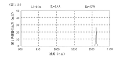
図9は、ファイバブラッググレーティング14の波長を例えば波長1112nmとした構成における光ファイバレーザ光源100の出力スペクトル図である。
The wavelength of the fiber Bragg grating 14 is the wavelength of the desired output light.
FIG. 9 is an output spectrum diagram of the optical fiber
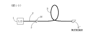
図10に示すように増幅光導波ファイバ3の出力側端部を無反射端末8’とした場合、増幅光導波ファイバ3の出力側端部からは図11に示すように波長915nmの励起光eと波長1050nm〜1100nmのブロードな放出光rが出力される。
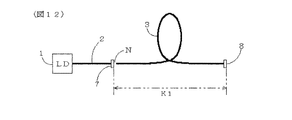
図12に示すようにように増幅光導波ファイバ3の出力側端部に出力側ハーフミラー膜8を設けて第1共振器K1を構成した場合、出力側ハーフミラー膜8の出力は図13に示すようなスペクトルとすることが出来る。
すなわち、第1共振器K1を設けたことによって、1100nmよりも長い波長帯域でも出力の安定化・ノイズ低減が可能となる。
As shown in FIG. 10, when the output side end of the amplified
As shown in FIG. 12, when the first resonator K1 is configured by providing the output-side
That is, by providing the first resonator K1, output can be stabilized and noise can be reduced even in a wavelength band longer than 1100 nm.
図14の(a)は、平行平板共振器(ファブリペローエタロン)における空隙の距離dを10μmとしたときの透過率−波長特性図である。
空隙の距離dが10μmのとき、透過率のピーク間隔は約60nmになる。
図14の(b)は、平行平板共振器における空隙の距離dを20μmとしたときの透過率−波長特性図である。
空隙の距離dが20μmのとき、透過率のピーク間隔は約30nmになる。
図14の(c)は、平行平板共振器における空隙の距離dを30μmとしたときの透過率−波長特性図である。
空隙の距離dが30μmのとき、透過率のピーク間隔は約20nmになる。
光ファイバレーザ光源100における入力側空隙Nと出力側空隙Sが平行平板共振器における空隙と同様の機能を奏するため、入力側空隙Nの距離Lnと出力側空隙Sの距離Lsを20μm以下とすることで、透過率のピーク間隔が約30nm以上となり、モードホップが起こりにくくなり、出力の安定性を向上できる。
FIG. 14A is a transmittance-wavelength characteristic diagram when the gap distance d in the parallel plate resonator (Fabry-Perot etalon) is 10 μm.
When the gap distance d is 10 μm, the transmittance peak interval is about 60 nm.
FIG. 14B is a transmittance-wavelength characteristic diagram when the gap distance d in the parallel plate resonator is 20 μm.
When the gap distance d is 20 μm, the transmittance peak interval is about 30 nm.
FIG. 14C is a transmittance-wavelength characteristic diagram when the gap distance d in the parallel plate resonator is 30 μm.
When the gap distance d is 30 μm, the transmittance peak interval is about 20 nm.
Since the input side gap N and the output side gap S in the optical fiber
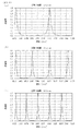
図15の(a)は、増幅光導波ファイバ3の長さL3を15mとしたときの第1共振器K1の出力−波長特性図である。
図15の(b)は、増幅光導波ファイバ3の長さL3を14mとしたときの第1共振器K1の出力−波長特性図である。
増幅光導波ファイバ3の長さL3は、所望の波長帯域の放出光を放出させるために調整される。
FIG. 15A is an output-wavelength characteristic diagram of the first resonator K1 when the length L3 of the amplified
FIG. 15B is an output-wavelength characteristic diagram of the first resonator K1 when the length L3 of the amplified
The length L3 of the amplified
図16の(a)は、出力側ハーフミラー膜8の反射率Rsを約50%としたときの第1共振器K1の出力−波長特性図である。
図16の(b)は、出力側ハーフミラー膜8の反射率Rsを約40%としたときの第1共振器K1の出力−波長特性図である。
出力側ハーフミラー膜8の反射率Rsは、所望の波長帯域の放出光を放出させるために4%〜90%の範囲で調整される。
FIG. 16A is an output-wavelength characteristic diagram of the first resonator K1 when the reflectance Rs of the output-side
FIG. 16B is an output-wavelength characteristic diagram of the first resonator K1 when the reflectance Rs of the output-side
The reflectance Rs of the output-side
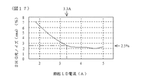
図17は、図2の光ファイバレーザ光源200におけるSHG光ノイズ(rms)−励起LD電流特性図である。
励起LD電流を増やすと、Yb3+の励起状態(反転分布状態)が安定することで、ノイズが低下する。
SHG光ノイズ(rms)を例えば2.5%以下に抑えたい場合、励起LD電流を3.3A以上にする必要がある。
しかし、励起LD電流を3.3A以上にすると、出力光のパワーも大きくなってしまい、SHG素子51の寿命を短くしてしまうなどの問題を生じる。
そこで、図18に示すように、フェルール33とフェルール34のファイバ挿入穴の中心軸をずらせておく。すると、増幅光導波ファイバ3のコア3aと出力光導波路ファイバ4のコア4aの中心軸がずれて、出力光のパワーを減衰させることが出来る。
また、図19に示すように、出力光導波路ファイバ4の1カ所で切断し、軸ずらし融着すれば、出力光のパワーを減衰させることが出来る。
FIG. 17 is an SHG optical noise (rms) -excitation LD current characteristic diagram in the optical fiber
When the excitation LD current is increased, the excitation state (inversion distribution state) of Yb3 + is stabilized, and noise is reduced.
In order to suppress SHG optical noise (rms) to 2.5% or less, for example, the excitation LD current needs to be 3.3 A or more.
However, when the pumping LD current is set to 3.3 A or more, the output light power also increases, causing problems such as shortening the life of the SHG element 51.
Therefore, as shown in FIG. 18, the center axes of the fiber insertion holes of the
Further, as shown in FIG. 19, the power of the output light can be attenuated by cutting at one point of the output
偏波分離素子13は、増幅光導波ファイバ4に980PANDAファイバ4’を隣接するように置いて、応力付与部の方向を互いに直角になるよう配置し、火炎等であぶり柔らかくして、増幅光導波ファイバ4と980PANDAファイバ4’を融着させ、延伸して製作される。
The
偏波分離素子13において、縦波は出力光導波ファイバ4を通過し、横波は隣接した980PANDAファイバ4’に乗り移り、出て行く。この結果、縦波のみを通過させることが出来る。
In the
増幅光導波ファイバ3と出力光導波ファイバ4の結合部では、結合損失による熱や残留励起光の漏れ出しによる熱を冷却すると共に温度変動による出力特性の変動を防ぐために、温調器10で一定温度に温調する。
In the coupling portion between the amplification
増幅光導波ファイバ3は、加熱すると波長が長くなる側に発振波長がシフトし、冷却すると波長が短くなる側に発振波長がシフトする。所望の発振波長が得られるように温調器50で温調する。
When the amplified
実施例1の光ファイバレーザ光源100によれば、第1光共振器K1と第2光共振器K2の2段階複合共振器構造とするため、出力安定性が高くなる。さらに、入力側空隙Nの距離Lnおよび出力側空隙Sの距離Lsを20μm以下としたため、モードホップが起こりにくくなり、この点でも出力安定性が高くなる。
According to the optical fiber
本発明の光ファイバレーザ光源は、レーザ顕微鏡装置,バイオ医療用分析装置,精密測定装置などに利用することが出来る。 The optical fiber laser light source of the present invention can be used in laser microscope devices, biomedical analyzers, precision measuring devices, and the like.
1 半導体励起レーザ
2 励起光導波ファイバ
3 増幅光導波ファイバ
4 出力光導波ファイバ
7 入力側フィルタ膜
8 出力側ハーフミラー膜
10 温調器
13 偏波分離素子
14 ファイバブラッググレーティング
17,18 反射防止膜
21 ビームスプリッタ
22 受光素子
23 制御部
27,28 溝
35 接着剤
37,38 接着剤
31,32 フェルール
33,34 フェルール
41,42 スリーブ
50 温調器
51 SHG素子
100 光ファイバレーザ光源
200 光ファイバレーザ光源
K1 第1共振器
K2 第2共振器
N 入力側空隙
S 出力側空隙
DESCRIPTION OF
Claims (21)
[ロ] 前記励起光導波ファイバ(2)から出力される励起光を入力して所定の波長帯域の放出光を放出すると共に光を導波する増幅光導波ファイバ(3)と、
[ハ]前記増幅光導波ファイバ(3)から出力される光を導波する出力光導波ファイバ(4)と、
[ニ]前記励起光導波ファイバ(2)の出力側端面に設けられ且つ前記増幅光導波ファイバ(3)の入力側端面との間に入力側空隙(N)を形成するか、又は、前記増幅光導波ファイバ(3)の入力側端面に設けられ且つ前記励起光導波ファイバ(2)の出力側端面との間に入力側空隙(N)を形成し、所定の波長帯域の光を反射し且つ所定の波長帯域の光を透過する入力側フィルタ膜(7)と、
[ホ]前記出力光導波ファイバ(4)の入力側端面に設けられ且つ前記増幅光導波ファイバ(3)の出力側端面との間に出力側空隙(S)を形成するか、又は、前記増幅光導波ファイバ(3)の出力側端面に設けられ且つ前記出力光導波ファイバ(4)の入力側端面との間に出力側空隙(S)を形成し、所定の波長帯域の光を反射し且つ所定の波長帯域の光を透過し、前記入力側フィルタ膜(7)との間で第1光共振器(K1)を構成する出力側ハーフミラー膜(8)と、
[へ]前記出力光導波路ファイバ(4)の内部に設けられ、前記入力側フィルタ膜(7)との間で第2光共振器(K2)を構成するファイバブラッググレーティング(14)とを具備し、
[ト]前記入力側空隙(N)の距離(Ln)および前記出力側空隙(S)の距離(Ls)が20μm以下である
ことを特徴とする光ファイバレーザ光源(100)。 [A] a pumping light waveguide fiber (2) for guiding pumping light output from the semiconductor pumping laser (1);
[B] An amplification optical waveguide fiber (3) that receives the excitation light output from the excitation light waveguide fiber (2), emits emission light of a predetermined wavelength band, and guides the light;
[C] an output optical waveguide fiber (4) for guiding the light output from the amplified optical waveguide fiber (3);
[D] An input side air gap (N) provided on the output side end face of the pumping optical waveguide fiber (2) and the input side end face of the amplification optical waveguide fiber (3), or the amplification An input side gap (N) is formed between the input side end face of the optical waveguide fiber (3) and the output side end face of the excitation light guide fiber (2), and reflects light in a predetermined wavelength band; An input side filter film (7) that transmits light of a predetermined wavelength band;
[E] An output side air gap (S) is formed between the output side end face of the output optical waveguide fiber (4) and the output side end face of the amplified optical waveguide fiber (3), or the amplification An output side air gap (S) is formed between the output side end face of the optical waveguide fiber (3) and the input side end face of the output optical waveguide fiber (4), and reflects light in a predetermined wavelength band; An output-side half mirror film (8) that transmits light in a predetermined wavelength band and forms a first optical resonator (K1) with the input-side filter film (7);
[F] A fiber Bragg grating (14) provided inside the output optical waveguide fiber (4) and constituting a second optical resonator (K2) with the input-side filter film (7). ,
[G] The optical fiber laser light source (100), wherein the distance (Ln) of the input side gap (N) and the distance (Ls) of the output side gap (S) are 20 μm or less.
前記増幅光導波路ファイバ(3)は、増幅媒体として希土類元素が添加されたコア(3a)と、前記コア(3a)の外側に設けた該コア(3a)より屈折率が低い内部クラッド(3b)と、前記内部クラッド(3b)の外側に設けた該内部クラッド(3b)より屈折率が低い外部クラッド(3c)とを有することを特徴とする光ファイバレーザ光源(100)。 The optical fiber laser light source (100) according to claim 1,
The amplification optical waveguide fiber (3) includes a core (3a) to which a rare earth element is added as an amplification medium, and an inner cladding (3b) having a lower refractive index than the core (3a) provided outside the core (3a). And an outer cladding (3c) having a lower refractive index than the inner cladding (3b) provided outside the inner cladding (3b).
前記増幅光導波ファイバ(3)の長さ(L3)が、前記所定の波長帯域の放出光が放出されるように調整されていることを特徴とする光ファイバレーザ光源(100)。 The optical fiber laser light source (100) according to claim 1 or 2,
An optical fiber laser light source (100), wherein the length (L3) of the amplification optical waveguide fiber (3) is adjusted so that the emitted light of the predetermined wavelength band is emitted.
前記入力側フィルタ膜(7)は、前記励起光に対して透過率95%以上で且つ前記放出光に対して反射率95%以上であることを特徴とする光ファイバレーザ光源(100)。 In the optical fiber laser light source (100) according to any one of claims 1 to 3,
The optical fiber laser light source (100), wherein the input filter film (7) has a transmittance of 95% or more for the excitation light and a reflectance of 95% or more for the emitted light.
前記出力側ハーフミラー膜(8)は、前記放出光に対して反射率4%〜90%であることを特徴とする光ファイバレーザ光源(100)。 In the optical fiber laser light source (100) according to any one of claims 1 to 4,
The optical fiber laser light source (100), wherein the output-side half mirror film (8) has a reflectance of 4% to 90% with respect to the emitted light.
前記増幅光導波ファイバ(3)のコア(3a)と前記出力光導波路ファイバ(4)のコア(4a)の中心軸をずらせたことを特徴とする光ファイバレーザ光源(100)。 In the optical fiber laser light source (100) according to any one of claims 1 to 5,
An optical fiber laser light source (100), wherein the central axes of the core (3a) of the amplification optical waveguide fiber (3) and the core (4a) of the output optical waveguide fiber (4) are shifted.
前記出力光導波路ファイバ(4)の1カ所で切断し且つ軸ずらし融着したこと特徴とする光ファイバレーザ光源(100)。 The optical fiber laser light source (100) according to any one of claims 1 to 6,
An optical fiber laser light source (100) characterized in that it is cut at one point of the output optical waveguide fiber (4) and fused by shifting its axis.
前記出力側ハーフミラー膜(8)と前記ファイバブラッググレーティング(14)の間に、偏光分離手段(13)を具備することを特徴とする光ファイバレーザ光源(100)。 In the optical fiber laser light source (100) according to any one of claims 1 to 7,
An optical fiber laser light source (100) comprising a polarization separation means (13) between the output-side half mirror film (8) and the fiber Bragg grating (14).
前記増幅光導波ファイバ(3)および前記出力光導波ファイバ(4)が、偏波保持型光ファイバであることを特徴とする光ファイバレーザ光源(100)。 In the optical fiber laser light source (100) according to any one of claims 1 to 9,
An optical fiber laser light source (100), wherein the amplification optical waveguide fiber (3) and the output optical waveguide fiber (4) are polarization maintaining optical fibers.
前記励起光導波ファイバ(2)の出力側端面または前記増幅光導波ファイバ(3)の入力側端面のうちの前記入力側フィルタ膜(7)が設けられていない方に反射防止膜(17)が設けられていることを特徴とする光ファイバレーザ光源(100)。 The optical fiber laser light source (100) according to any of claims 1 to 11,
Of the output side end face of the excitation light waveguide fiber (2) or the input side end face of the amplification optical waveguide fiber (3), an antireflection film (17) is provided on the side where the input side filter film (7) is not provided. An optical fiber laser light source (100) characterized by being provided.
前記増幅光導波ファイバ(3)の出力側端面または前記出力光導波路ファイバ(4)の入力側端面のうちの前記出力側ハーフミラー膜(8)が設けられていない方に反射防止膜(18)が設けられていることを特徴とする光ファイバレーザ光源(100)。 The optical fiber laser light source (100) according to any of claims 1 to 12,
Of the output side end face of the amplification optical waveguide fiber (3) or the input side end face of the output optical waveguide fiber (4), the antireflection film (18) is not provided on the output side half mirror film (8). An optical fiber laser light source (100) characterized in that is provided.
前記励起光導波ファイバ(2)の出力側端部がフェルール(31)に固定されており、前記増幅光導波ファイバ(3)の入力側端部がフェルール(32)に固定されており、
前記増幅光導波ファイバ(3)の出力側端部がフェルール(33)に固定されており、前記出力光導波ファイバ(4)の入力側端部がフェルール(34)に固定されていることを特徴とする光ファイバレーザ光源(100)。 The optical fiber laser light source (100) according to any of claims 1 to 13,
The output side end of the excitation light waveguide fiber (2) is fixed to the ferrule (31), and the input side end of the amplification light waveguide fiber (3) is fixed to the ferrule (32),
The output side end of the amplified optical waveguide fiber (3) is fixed to the ferrule (33), and the input side end of the output optical waveguide fiber (4) is fixed to the ferrule (34). An optical fiber laser light source (100).
前記フェルール(31〜34)が、セラミックスまたは透明ガラスからなることを特徴とする光ファイバレーザ光源(100)。 The optical fiber laser light source (100) according to claim 14,
The optical fiber laser light source (100), wherein the ferrule (31 to 34) is made of ceramics or transparent glass.
前記増幅光導波路ファイバ(3)が、増幅媒体として希土類元素が添加されたコア(3a)と、前記コア(3a)の外側に設けた該コア(3a)より屈折率が低い内部クラッド(3b)と、前記内部クラッド(3b)の外側に設けた該内部クラッド(3b)より屈折率が低い外部クラッド(3c)とを有する場合に、
前記増幅光導波ファイバ(3)の出力側端部の前記フェルール(33)に挿入する部分の前記外部クラッド(3c)を除去し、前記内部クラッド(3b)と同じかそれよりも高い屈折率の接着剤(35)により前記フェルール(33)の挿入穴と前記内部クラッド(3b)の間を充填し固めたことを特徴とする光ファイバレーザ光源(100)。 The optical fiber laser light source (100) according to claim 14 or 15,
The amplification optical waveguide fiber (3) includes a core (3a) to which a rare earth element is added as an amplification medium, and an inner cladding (3b) having a refractive index lower than that of the core (3a) provided outside the core (3a). And an outer cladding (3c) having a lower refractive index than the inner cladding (3b) provided outside the inner cladding (3b),
The outer cladding (3c) of the portion inserted into the ferrule (33) at the output side end of the amplified optical waveguide fiber (3) is removed, and the refractive index is the same as or higher than that of the inner cladding (3b). An optical fiber laser light source (100), wherein the space between the insertion hole of the ferrule (33) and the inner clad (3b) is filled with an adhesive (35) and hardened.
前記フェルール(34)が透明ガラスからなる場合に、
前記出力光導波ファイバ(4)の入力側端部を挿入する前記フェルール(34)のファイバ挿入口が円錐形状に加工されると共に金メッキまたは銀メッキ(36)がなされていることを特徴とする光ファイバレーザ光源(100)。 The optical fiber laser light source (100) according to claim 16,
When the ferrule (34) is made of transparent glass,
The fiber insertion port of the ferrule (34) into which the input side end of the output optical waveguide fiber (4) is inserted is processed into a conical shape and is gold-plated or silver-plated (36). Fiber laser light source (100).
前記フェルール(31)の出力側端面と前記フェルール(32)の入力側端面の少なくとも一方に円環状の溝(27)を設け、前記フェルール(31)の出力側端面と前記フェルール(32)の入力側端面の前記溝(27)より外側の部分を接着剤(37)で接着し、
前記フェルール(33)の出力側端面と前記フェルール(34)の入力側端面の少なくとも一方に円環状の溝(28)を設け、前記フェルール(33)の出力側端面と前記フェルール(34)の入力側端面の前記溝(28)より外側の部分を接着剤(38)で接着したことを特徴とする光ファイバレーザ光源(100)。 The optical fiber laser light source (100) according to any of claims 14 to 17,
An annular groove (27) is provided in at least one of the output side end face of the ferrule (31) and the input side end face of the ferrule (32), and the output side end face of the ferrule (31) and the input of the ferrule (32) are provided. Adhering a portion of the side end surface outside the groove (27) with an adhesive (37),
An annular groove (28) is provided in at least one of the output side end face of the ferrule (33) and the input side end face of the ferrule (34), and the output side end face of the ferrule (33) and the input of the ferrule (34) are provided. An optical fiber laser light source (100), wherein a portion of the side end face outside the groove (28) is bonded with an adhesive (38).
前記フェルール(31)および前記フェルール(32)を同径の円筒状とし、両者をスリーブ(41)で保持し、
前記フェルール(33)および前記フェルール(34)を同径の円筒状とし、両者をスリーブ(42)で保持したことを特徴とする光ファイバレーザ光源(100)。 The optical fiber laser light source (100) according to any of claims 14 to 18,
The ferrule (31) and the ferrule (32) are cylindrical with the same diameter, and both are held by a sleeve (41),
An optical fiber laser light source (100), wherein the ferrule (33) and the ferrule (34) are cylindrical with the same diameter, and both are held by a sleeve (42).
前記増幅光導波ファイバ(3)と前記出力光導波ファイバ(4)の結合部に温調手段(10)を設けたことを特徴とする光ファイバレーザ光源(100)。 The optical fiber laser light source (100) according to any of claims 1 to 19,
An optical fiber laser light source (100), characterized in that a temperature control means (10) is provided at a joint between the amplified optical waveguide fiber (3) and the output optical waveguide fiber (4).
前記増幅光導波ファイバ(3)の温調手段(50)を設けたことを特徴とする光ファイバレーザ光源(100)。 The optical fiber laser light source (100) according to any of claims 1 to 20,
An optical fiber laser light source (100) characterized in that a temperature adjusting means (50) for the amplification optical waveguide fiber (3) is provided.
Priority Applications (1)
| Application Number | Priority Date | Filing Date | Title |
|---|---|---|---|
| JP2011075601A JP2012209510A (en) | 2011-03-30 | 2011-03-30 | Optical fiber laser light source |
Applications Claiming Priority (1)
| Application Number | Priority Date | Filing Date | Title |
|---|---|---|---|
| JP2011075601A JP2012209510A (en) | 2011-03-30 | 2011-03-30 | Optical fiber laser light source |
Publications (1)
| Publication Number | Publication Date |
|---|---|
| JP2012209510A true JP2012209510A (en) | 2012-10-25 |
Family
ID=47188989
Family Applications (1)
| Application Number | Title | Priority Date | Filing Date |
|---|---|---|---|
| JP2011075601A Withdrawn JP2012209510A (en) | 2011-03-30 | 2011-03-30 | Optical fiber laser light source |
Country Status (1)
| Country | Link |
|---|---|
| JP (1) | JP2012209510A (en) |
Cited By (5)
| Publication number | Priority date | Publication date | Assignee | Title |
|---|---|---|---|---|
| JP2013130665A (en) * | 2011-12-21 | 2013-07-04 | Yazaki Corp | Optical transmission line |
| JP2015023204A (en) * | 2013-07-22 | 2015-02-02 | 株式会社島津製作所 | Fiber coupling laser module |
| JP2015111200A (en) * | 2013-12-06 | 2015-06-18 | 住友電気工業株式会社 | Ferrule-attached optical fiber and manufacturing method thereof |
| WO2015106606A1 (en) * | 2014-01-17 | 2015-07-23 | 华南理工大学 | Tunable narrow-linewidth single-frequency linear-polarization laser device |
| KR101766404B1 (en) * | 2015-08-21 | 2017-08-09 | 성기석 | Guide Laser Diode Package and Machining Apparatus adopting the LD |
-
2011
- 2011-03-30 JP JP2011075601A patent/JP2012209510A/en not_active Withdrawn
Cited By (6)
| Publication number | Priority date | Publication date | Assignee | Title |
|---|---|---|---|---|
| JP2013130665A (en) * | 2011-12-21 | 2013-07-04 | Yazaki Corp | Optical transmission line |
| JP2015023204A (en) * | 2013-07-22 | 2015-02-02 | 株式会社島津製作所 | Fiber coupling laser module |
| JP2015111200A (en) * | 2013-12-06 | 2015-06-18 | 住友電気工業株式会社 | Ferrule-attached optical fiber and manufacturing method thereof |
| WO2015106606A1 (en) * | 2014-01-17 | 2015-07-23 | 华南理工大学 | Tunable narrow-linewidth single-frequency linear-polarization laser device |
| US9787050B2 (en) | 2014-01-17 | 2017-10-10 | South China University Of Technology | Tunable narrow-linewidth single-frequency linear-polarization laser device |
| KR101766404B1 (en) * | 2015-08-21 | 2017-08-09 | 성기석 | Guide Laser Diode Package and Machining Apparatus adopting the LD |
Similar Documents
| Publication | Publication Date | Title |
|---|---|---|
| US8611003B2 (en) | Double clad fiber laser device | |
| JP5260885B2 (en) | Optical fiber leakage light processing structure | |
| US6816652B1 (en) | Pump fiber bundle coupler for double-clad fiber devices | |
| JP5236081B2 (en) | Optical combiner and fiber laser device using the same | |
| US9537282B2 (en) | System and method for a multi-mode pump in an optical amplifier | |
| JP6356856B1 (en) | Clad mode light removal structure and laser device | |
| CN109716599B (en) | Fiber coupled laser source pump with wavelength division multiplexer, isolator, tap filter and photodetector | |
| US7430225B2 (en) | Fiber laser beam processing apparatus | |
| US8665514B2 (en) | Multi-core optical amplification fiber wound with decreasing radius of curvature | |
| JP2012209510A (en) | Optical fiber laser light source | |
| US20150247972A1 (en) | Optical fiber, fiber laser, and optical fiber manufacturing method | |
| US8018982B2 (en) | Sliced fiber bragg grating used as external cavity for semiconductor laser and solid state laser | |
| US7801186B2 (en) | Light source | |
| JP5643632B2 (en) | Multi-port coupler, and optical fiber amplifier, fiber laser apparatus and resonator using the same | |
| WO2020203136A1 (en) | Fiber laser device | |
| US7724424B2 (en) | Optical module and optical amplification module | |
| JP4899705B2 (en) | Optical amplification module | |
| US20090067188A1 (en) | Light source | |
| KR102027376B1 (en) | Laser resonator | |
| KR101889293B1 (en) | Laser resonator | |
| JP2021136242A (en) | Fiber laser device | |
| JP2009059953A (en) | Optical fiber laser | |
| JPWO2007043558A1 (en) | Optical receptacle, optical module, and method for reducing variation in coupling efficiency in optical receptacle | |
| WO2011007693A1 (en) | Fusion-splicing structure, optical waveguide element having fusion-splicing structure, and light source device using optical waveguide element, and splicing method | |
| JP6792716B2 (en) | How to set heating conditions, how to make fiber Bragg gratings, and how to make fiber laser systems |
Legal Events
| Date | Code | Title | Description |
|---|---|---|---|
| A300 | Application deemed to be withdrawn because no request for examination was validly filed |
Free format text: JAPANESE INTERMEDIATE CODE: A300 Effective date: 20140603 |