JP2012208397A - Optical film, polarizer, liquid crystal display and homeotropic surfactant - Google Patents
Optical film, polarizer, liquid crystal display and homeotropic surfactant Download PDFInfo
- Publication number
- JP2012208397A JP2012208397A JP2011075247A JP2011075247A JP2012208397A JP 2012208397 A JP2012208397 A JP 2012208397A JP 2011075247 A JP2011075247 A JP 2011075247A JP 2011075247 A JP2011075247 A JP 2011075247A JP 2012208397 A JP2012208397 A JP 2012208397A
- Authority
- JP
- Japan
- Prior art keywords
- liquid crystal
- group
- film
- ring
- anisotropic layer
- Prior art date
- Legal status (The legal status is an assumption and is not a legal conclusion. Google has not performed a legal analysis and makes no representation as to the accuracy of the status listed.)
- Withdrawn
Links
Images
Landscapes
- Liquid Crystal (AREA)
- Polarising Elements (AREA)
Abstract
Description
本発明は、液晶表示装置の光学補償等に有用な光学フィルム、垂直配向剤、並びにそれを有する偏光板及び液晶表示装置に関する。 The present invention relates to an optical film useful for optical compensation of a liquid crystal display device, a vertical alignment agent, a polarizing plate having the same, and a liquid crystal display device.
従来、液晶分子のハイブリッド配向状態を固定して形成された光学異方性層を、TNモード液晶表示装置の光学補償に利用することが提案されている。中でも、近年、高いΔn及び低い波長分散性を有するディスコティック液晶化合物が種々開発され、これらの化合物の光学補償部材への利用が期待されている(例えば、特許文献1及び2)。
Conventionally, it has been proposed to use an optically anisotropic layer formed by fixing the hybrid alignment state of liquid crystal molecules for optical compensation of a TN mode liquid crystal display device. In particular, in recent years, various discotic liquid crystal compounds having high Δn and low wavelength dispersion have been developed, and use of these compounds in optical compensation members is expected (for example,
ここで「ディスコティック液晶分子のハイブリッド配向」とは、ディスコティック液晶分子の円盤面と層面とのなす角度(以下、「チルト角」という)が、層厚み方向において変化(増加又は減少)している配向状態である。当該光学異方性層は、一般的には、配向膜の表面上でディスコティック液晶化合物を含有する組成物を配向させて形成されるので、該層には配向膜界面と空気界面とが存在する。ハイブリッド配向には、前記チルト角が、配向膜界面側で大きく、空気界面側で小さくなっている態様(即ち、チルト角が配向膜界面から空気界面に向けて減少している態様、以下、「逆ハイブリッド配向」という)、及び前記チルト角が、配向膜界面側で小さく、空気界面側で大きくなっている態様(即ち、チルト角が配向膜界面から空気界面に向けて増加している態様、以下「正ハイブリッド配向」という)の2態様がある。従来、ディスコティック液晶分子を用いた光学補償フィルムとしては、後者の態様、即ち、正ハイブリッド配向、が一般的である。 Here, “hybrid alignment of discotic liquid crystal molecules” means that the angle (hereinafter referred to as “tilt angle”) between the disc surface and the layer surface of the discotic liquid crystal molecules changes (increases or decreases) in the layer thickness direction. Orientation state. Since the optically anisotropic layer is generally formed by orienting a composition containing a discotic liquid crystal compound on the surface of the alignment film, the layer has an alignment film interface and an air interface. To do. In hybrid alignment, the tilt angle is large on the alignment film interface side and small on the air interface side (that is, the tilt angle is decreased from the alignment film interface toward the air interface, hereinafter, “ `` Reverse hybrid orientation ''), and the aspect in which the tilt angle is small on the alignment film interface side and large on the air interface side (that is, the tilt angle increases from the alignment film interface toward the air interface, There are two modes (hereinafter referred to as “positive hybrid orientation”). Conventionally, as the optical compensation film using discotic liquid crystal molecules, the latter mode, that is, the positive hybrid alignment is generally used.
液晶化合物の逆ハイブリッド配向を固定した光学異方性層を有する光学フィルムについても、種々提案されている(例えば、特許文献3及び4)。ところで、例えば、配向膜のラビング処理面上で、ディスコティック液晶化合物の分子を、その円盤面を配向膜面に対して垂直に配向(以下、「垂直配向」という)させると、ディスコティック液晶分子は、ラビング処理によって形成された溝に、その円盤面をはめ込んだ状態で垂直配向するのが一般的である。よって、従来実現している逆ハイブリッド配向状態では、配向膜界面で垂直配向しているディスコティック液晶分子は、その円盤面を、ラビング方向に平行にして垂直配向しているものがほとんどである。その様な、配向膜面界面でディスコティック液晶分子がその円盤面をラビング方向に平行にして配向している、上記従来の逆ハイブリッド配向を固定した光学異方性層では、遅相軸は、ラビング方向に対して平行方向に発現することになる。一方、連続生産では、長尺フィルムの搬送方向に沿ってラビング処理が実施されるのが一般的である。よって、上記逆ハイブリッド配向を固定した光学異方性層を、長尺のフィルム状に連続的に生産する場合は、その遅相軸は、長手方向に対して平行になっている。しかし、かかる特性の光学異方性層を連続的に長尺状に生産しても、その後、長尺状の偏光子と、長手方向を一致させて貼合することはできず、そのことが、実用化の弊害となっている。 Various optical films having an optically anisotropic layer in which the reverse hybrid orientation of a liquid crystal compound is fixed have been proposed (for example, Patent Documents 3 and 4). By the way, for example, when the discotic liquid crystal compound molecules are aligned perpendicularly to the alignment film surface (hereinafter referred to as “vertical alignment”) on the rubbing-treated surface of the alignment film, the discotic liquid crystal molecules In general, the vertical orientation is performed with the disk surface fitted in the groove formed by rubbing. Therefore, in the reverse hybrid alignment state realized in the past, most of the discotic liquid crystal molecules vertically aligned at the alignment film interface are vertically aligned with the disk surface parallel to the rubbing direction. In such an optically anisotropic layer in which the conventional reverse hybrid orientation is fixed, the discotic liquid crystal molecules are oriented with the disc surface parallel to the rubbing direction at the orientation film surface interface, and the slow axis is It appears in a direction parallel to the rubbing direction. On the other hand, in continuous production, rubbing is generally performed along the conveying direction of a long film. Therefore, when the optically anisotropic layer in which the reverse hybrid orientation is fixed is continuously produced in the form of a long film, the slow axis is parallel to the longitudinal direction. However, even if an optically anisotropic layer having such characteristics is continuously produced in a long shape, it cannot be bonded with the long polarizer so that the longitudinal direction coincides. It has become a negative effect of practical use.
ディスコティック液晶化合物及び棒状液晶化合物を含めて、配向膜界面側のチルト角を大きくする、すなわち液晶化合物を垂直配向させる方法としては、例えば、配向制御剤を光学異方性層に含有させることが提案されている(例えば特許文献4及び5)。 As a method for increasing the tilt angle on the alignment film interface side including the discotic liquid crystal compound and the rod-shaped liquid crystal compound, that is, for vertically aligning the liquid crystal compound, for example, an alignment controller is included in the optically anisotropic layer. It has been proposed (for example, Patent Documents 4 and 5).
上記した通り、従来、液晶分子を用いた光学補償フィルムとしては、正ハイブリッド配向を固定して形成した光学異方性層を有する光学補償フィルムが一般的である。本発明者が鋭意検討した結果、正ハイブリッド配向状態の液晶分子の配向は、ミクロレベルでみると若干の乱れがあり、このミクロレベルの配向乱れは、光学異方性層のミクロ配向軸ズレとなって現れ、光学補償部材として液晶表示装置に用いた場合に、正面コントラスト(CR)を低下させる一因となることがわかった。特に近年では、正面コントラストの上昇が顕著であり、従来は問題視されていなかった正面CRの低下原因に対しても、解決することが求められている。一方、従来の逆ハイブリッド配向を利用する態様には、上記した通り、製造上の問題点が存在する。 As described above, conventionally, as an optical compensation film using liquid crystal molecules, an optical compensation film having an optically anisotropic layer formed by fixing positive hybrid alignment is generally used. As a result of intensive studies by the present inventors, the alignment of liquid crystal molecules in the positive hybrid alignment state is slightly disturbed at the micro level, and this micro level of alignment disorder is caused by the micro-alignment axis deviation of the optical anisotropic layer. It has been found that, when used in a liquid crystal display device as an optical compensation member, it becomes a cause of lowering the front contrast (CR). In particular, in recent years, the increase in front contrast has been remarkable, and it has been demanded to solve the cause of the decrease in front CR, which has not been regarded as a problem in the past. On the other hand, in the aspect using the conventional reverse hybrid orientation, as described above, there are manufacturing problems.
逆ハイブリッド配向を形成するためには、配向膜界面で液晶分子を垂直配向させる必要がある。配向膜界面で液晶分子を安定的に垂直配向させるためには、配向膜側界面に高い偏在性を示す配向制御剤を併用することが有効である。しかし、そのような特性の配向制御剤を使用すると、光学異方性層と配向膜との界面の密着性が低下するという問題がある。
本発明は、上記問題点に鑑みなされたものであって、配向膜界面において液晶分子が安定な垂直配向状態にあり、しかも配向膜と光学異方性層との密着性にも優れた光学フィルム、その製造に利用可能な垂直配向剤、並びにそれを有する偏光板及び液晶表示装置を提供することを課題とする。
In order to form reverse hybrid alignment, it is necessary to vertically align liquid crystal molecules at the alignment film interface. In order to stably vertically align the liquid crystal molecules at the alignment film interface, it is effective to use an alignment control agent exhibiting high uneven distribution at the alignment film side interface. However, when an alignment control agent having such characteristics is used, there is a problem that the adhesion at the interface between the optically anisotropic layer and the alignment film is lowered.
The present invention has been made in view of the above problems, and an optical film in which liquid crystal molecules are in a stable vertical alignment state at the alignment film interface and has excellent adhesion between the alignment film and the optically anisotropic layer. Another object of the present invention is to provide a vertical alignment agent that can be used in the production thereof, and a polarizing plate and a liquid crystal display device having the same.
前記課題を解決するための手段は、以下の通りである。
[1] 支持体とラビング処理された配向膜と液晶化合物を含む光学異方性層とをこの順で有する光学フィルムであって、
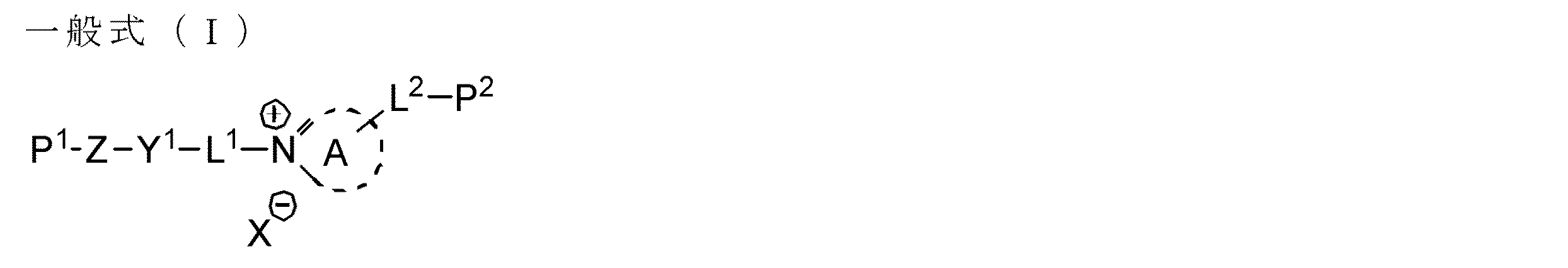
前記光学異方性層が、少なくとも1種の下記一般式(I)で表されるオニウム化合物を含むことを特徴とする光学フィルム:
[2] 前記少なくとも1種の一般式(I)で表されるオニウム化合物が、下記一般式(I−1)又は(I−2)で表される化合物である[1]の光学フィルム:
[3] 前記少なくとも1種の一般式(I)で表されるオニウム化合物が、下記一般式(I−3)又は(I−4)で表される化合物の少なくともいずれかである[2]の光学フィルム:
[4] 前記配向膜が、変性又は未変性ポリビニルアルコールを主成分として含有する膜である[1]〜[3]のいずれかの光学フィルム。
[5] 前記光学異方性層が、さらに、少なくとも1種のフルオロ脂肪族基を有する繰り返し単位を含む共重合体を含有する[1]〜[4]のいずれかの光学フィルム。
[6] 前記液晶化合物の分子の配向膜側チルト角が、空気界面側チルト角より大きい配向状態に固定される[1]〜[5]のいずれかの光学フィルム。
[7] 前記光学異方性層の遅相軸方向が、前記配向膜のラビング方向と直交する[1]〜[6]のいずれかの光学フィルム。
[8] 前記液晶化合物が、ディスコティック液晶化合物である[1]〜[7]のいずれかの光学フィルム。
[9] 前記ディスコティック液晶化合物が、下記式(X)を円盤状コアとして有するディスコティック液晶化合物である[8]の光学フィルム:
[10] 前記オニウム化合物の添加量が、前記液晶化合物100質量部に対し、0.5〜3質量部である[1]〜[9]のいずれかの光学フィルム。
[11] 前記フルオロ脂肪族基を有する繰り返し単位を含む共重合体の添加量が、前記液晶化合物100質量部に対し、0.2〜2.0質量部である[5]〜[10]のいずれかの光学フィルム。
[12] 偏光膜と、[1]〜[11]のいずれかの光学フィルムと、を少なくとも有する偏光板。
[13] [12]の偏光板を少なくとも有する液晶表示装置。
[14] TNモードである[13]の液晶表示装置。
[15] 下記一般式(I)で表されるオニウム化合物を含むことを特徴とする垂直配向剤:
[1] An optical film having a support, a rubbing-treated alignment film, and an optically anisotropic layer containing a liquid crystal compound in this order,
The optically anisotropic layer contains at least one onium compound represented by the following general formula (I):
[2] The optical film of [1], wherein the at least one onium compound represented by the general formula (I) is a compound represented by the following general formula (I-1) or (I-2):
[3] The onium compound represented by the general formula (I) is at least one of the compounds represented by the following general formula (I-3) or (I-4): Optical film:
[4] The optical film according to any one of [1] to [3], wherein the alignment film is a film containing a modified or unmodified polyvinyl alcohol as a main component.
[5] The optical film according to any one of [1] to [4], wherein the optically anisotropic layer further contains a copolymer containing a repeating unit having at least one fluoroaliphatic group.
[6] The optical film according to any one of [1] to [5], wherein the alignment film side tilt angle of the molecules of the liquid crystal compound is fixed in an alignment state larger than the air interface side tilt angle.
[7] The optical film according to any one of [1] to [6], wherein a slow axis direction of the optically anisotropic layer is orthogonal to a rubbing direction of the alignment film.
[8] The optical film according to any one of [1] to [7], wherein the liquid crystal compound is a discotic liquid crystal compound.
[9] The optical film of [8], wherein the discotic liquid crystal compound is a discotic liquid crystal compound having the following formula (X) as a discotic core:
[10] The optical film according to any one of [1] to [9], wherein an addition amount of the onium compound is 0.5 to 3 parts by mass with respect to 100 parts by mass of the liquid crystal compound.
[11] The amount of the copolymer including the repeating unit having a fluoroaliphatic group is 0.2 to 2.0 parts by mass with respect to 100 parts by mass of the liquid crystal compound. Any optical film.
[12] A polarizing plate having at least a polarizing film and the optical film of any one of [1] to [11].
[13] A liquid crystal display device having at least the polarizing plate of [12].
[14] The liquid crystal display device according to [13], which is a TN mode.
[15] A vertical alignment agent comprising an onium compound represented by the following general formula (I):
本発明によれば、配向膜界面において液晶分子が安定な垂直配向状態にあり、しかも配向膜と光学異方性層との密着性にも優れた光学フィルム、その製造に利用可能な垂直配向剤、並びにそれを有する偏光板及び液晶表示装置を提供することができる。 According to the present invention, an optical film in which liquid crystal molecules are in a stable vertical alignment state at the alignment film interface and excellent in adhesion between the alignment film and the optically anisotropic layer, and a vertical alignment agent that can be used in the production thereof In addition, a polarizing plate and a liquid crystal display device including the same can be provided.
以下、本発明について詳細に説明する。
なお、本実施形態の説明において、「平行」あるいは「直交」とは、厳密な角度±5°未満の範囲内であることを意味する。厳密な角度との誤差は、4°未満であることが好ましく、3°未満であることがより好ましい。
また、角度について、「+」は時計周り方向を意味し、「−」は反時計周り方向を意味するものとする。
また、「遅相軸」は、屈折率が最大となる方向を意味し、更に屈折率の測定波長は、特別な記述がない限り、可視光域(λ=550nm)での値である。
Hereinafter, the present invention will be described in detail.
In the description of this embodiment, “parallel” or “orthogonal” means that the angle is within a strict angle of less than ± 5 °. The error from the exact angle is preferably less than 4 °, more preferably less than 3 °.
Regarding the angle, “+” means the clockwise direction, and “−” means the counterclockwise direction.
The “slow axis” means the direction in which the refractive index is maximized, and the measurement wavelength of the refractive index is a value in the visible light region (λ = 550 nm) unless otherwise specified.
また、本実施形態の説明において「偏光板」とは、特別な記述がない限り、長尺の偏光板、及び液晶装置に組み込まれる大きさに裁断された偏光板の両者を含む意味で用いている。なお、ここでいう「裁断」には「打ち抜き」及び「切り出し」等も含むものとする。また、本実施形態の説明では、「偏光子」と「偏光板」とを区別して用いるが、「偏光板」は「偏光子」の少なくとも片面に該偏光子を保護する透明保護膜を有する積層体のことを意味するものとする。 In the description of this embodiment, the term “polarizing plate” is used to mean both a long polarizing plate and a polarizing plate cut into a size incorporated in a liquid crystal device unless otherwise specified. Yes. Here, “cutting” includes “punching” and “cutting out”. In the description of the present embodiment, “polarizer” and “polarizing plate” are distinguished from each other, but “polarizing plate” is a laminate having a transparent protective film for protecting the polarizer on at least one surface of “polarizer”. It shall mean the body.
また、本実施形態の説明において「分子対称軸」とは、分子が回転対称軸を有する場合は、当該対称軸を指すが、厳密な意味で、分子が回転対称性であることを要求するものではない。一般的に、ディスコティック液晶性化合物において、分子対称軸は、円盤面の中心を貫く円盤面に対して垂直な軸と一致し、棒状液晶性化合物において、分子対称軸は、分子の長軸と一致する。 In the description of the present embodiment, the “molecular symmetry axis” refers to a symmetry axis when the molecule has a rotational symmetry axis, but strictly requires that the molecule is rotationally symmetric. is not. In general, in a discotic liquid crystalline compound, the molecular symmetry axis coincides with an axis perpendicular to the disc surface passing through the center of the disc surface, and in a rod-like liquid crystalline compound, the molecular symmetry axis is the long axis of the molecule. Match.
また、本明細書において、Re(λ)、Rth(λ)は、各々、波長λにおける面内のレターデーション、及び厚さ方向のレターデーションを表す。Re(λ)はKOBRA 21ADH、又はWR(王子計測機器(株)製)において、波長λnmの光をフィルム法線方向に入射させて測定される。測定波長λnmの選択にあたっては、波長選択フィルターをマニュアルで交換するか、または測定値をプログラム等で変換して測定することができる。測定されるフィルムが、1軸又は2軸の屈折率楕円体で表されるものである場合には、以下の方法によりRth(λ)が算出される。なお、この測定方法は、後述する光学異方性層中のディスコティック液晶分子の配向膜側の平均チルト角、その反対側の平均チルト角の測定においても一部利用される。
Rth(λ)は、前記Re(λ)を、面内の遅相軸(KOBRA 21ADH、又はWRにより判断される)を傾斜軸(回転軸)として(遅相軸がない場合には、フィルム面内の任意の方向を回転軸とする)のフィルム法線方向に対して法線方向から片側50°まで10度ステップで各々その傾斜した方向から波長λnmの光を入射させて全部で6点測定し、その測定されたレターデーション値と平均屈折率の仮定値及び入力された膜厚値を基にKOBRA 21ADH又はWRが算出する。上記において、法線方向から面内の遅相軸を回転軸として、ある傾斜角度にレターデーションの値がゼロとなる方向をもつフィルムの場合には、その傾斜角度より大きい傾斜角度でのレターデーション値はその符号を負に変更した後、KOBRA 21ADH、又はWRが算出する。なお、遅相軸を傾斜軸(回転軸)として(遅相軸がない場合には、フィルム面内の任意の方向を回転軸とする)、任意の傾斜した2方向からレターデーション値を測定し、その値と平均屈折率の仮定値、及び入力された膜厚値を基に、以下の式(A)、及び式(III)よりRthを算出することもできる。
In this specification, Re (λ) and Rth (λ) represent in-plane retardation and retardation in the thickness direction at the wavelength λ, respectively. Re (λ) is measured with KOBRA 21ADH or WR (manufactured by Oji Scientific Instruments Co., Ltd.) by making light having a wavelength of λ nm incident in the normal direction of the film. In selecting the measurement wavelength λnm, the wavelength selection filter can be exchanged manually, or the measurement value can be converted by a program or the like. When the film to be measured is represented by a uniaxial or biaxial refractive index ellipsoid, Rth (λ) is calculated by the following method. This measuring method is also partially used for measuring the average tilt angle on the alignment film side of the discotic liquid crystal molecules in the optically anisotropic layer, which will be described later, and the average tilt angle on the opposite side.
Rth (λ) is the film surface when Re (λ) is used and the in-plane slow axis (determined by KOBRA 21ADH or WR) is the tilt axis (rotation axis) (if there is no slow axis) Measurement is performed at a total of 6 points by injecting light of wavelength λ nm from each inclined direction in steps of 10 degrees from the normal direction to 50 ° on one side with respect to the film normal direction (with any rotation direction as the rotation axis). Then, KOBRA 21ADH or WR is calculated based on the measured retardation value, the assumed value of the average refractive index, and the input film thickness value. In the above case, in the case of a film having a direction in which the retardation value is zero at a certain tilt angle with the in-plane slow axis from the normal direction as the rotation axis, retardation at a tilt angle larger than the tilt angle. The value is calculated by KOBRA 21ADH or WR after changing its sign to negative. The retardation value is measured from two inclined directions with the slow axis as the tilt axis (rotation axis) (if there is no slow axis, the arbitrary direction in the film plane is the rotation axis). Rth can also be calculated from the following formula (A) and formula (III) based on the value, the assumed value of the average refractive index, and the input film thickness value.
Rth={(nx+ny)/2−nz}×d・・・・・・・・・・・式(III)
Rth = {(nx + ny) / 2−nz} × d (formula (III))
測定されるフィルムが、1軸や2軸の屈折率楕円体で表現できないもの、いわゆる光学軸(optic axis)がないフィルムの場合には、以下の方法により、Rth(λ)は算出される。Rth(λ)は、前記Re(λ)を、面内の遅相軸(KOBRA 21ADH、又はWRにより判断される)を傾斜軸(回転軸)として、フィルム法線方向に対して−50°から+50°まで10°ステップで各々その傾斜した方向から波長λnmの光を入射させて11点測定し、その測定されたレターデーション値と平均屈折率の仮定値及び入力された膜厚値を基にKOBRA 21ADH又はWRが算出する。また、上記の測定において、平均屈折率の仮定値は、ポリマーハンドブック(JOHN WILEY&SONS,INC)、各種光学フィルムのカタログの値を使用することができる。平均屈折率の値が既知でないものについては、アッベ屈折計で測定することができる。主な光学フィルムの平均屈折率の値を以下に例示する:
セルロースアシレート(1.48)、シクロオレフィンポリマー(1.52)、ポリカーボネート(1.59)、ポリメチルメタクリレート(1.49)、ポリスチレン(1.59)である。
これら平均屈折率の仮定値と膜厚を入力することで、KOBRA 21ADH又はWRはnx、ny、nzを算出する。この算出されたnx,ny,nzよりNz=(nx−nz)/(nx−ny)が更に算出される。
なお、屈折率の測定波長は、特に断らない限り、可視光域のλ=550nmでの値であり、Re及びRthの測定波長については、特に断らない限り、550nmとする。
When the film to be measured is a film that cannot be expressed by a uniaxial or biaxial refractive index ellipsoid, that is, a film without a so-called optical axis, Rth (λ) is calculated by the following method. Rth (λ) is from −50 ° to the normal direction of the film, with Re (λ) being the in-plane slow axis (determined by KOBRA 21ADH or WR) as the tilt axis (rotary axis). Measured at 11 points by making light of wavelength λ nm incident in 10 ° steps up to + 50 °, and based on the measured retardation value, average refractive index assumption value and input film thickness value. KOBRA 21ADH or WR is calculated. In the above measurement, as the assumed value of the average refractive index, values in the polymer handbook (John Wiley & Sons, Inc.) and catalogs of various optical films can be used. If the average refractive index is not known, it can be measured with an Abbe refractometer. Examples of the average refractive index values of main optical films are given below:
Cellulose acylate (1.48), cycloolefin polymer (1.52), polycarbonate (1.59), polymethyl methacrylate (1.49), and polystyrene (1.59).
The KOBRA 21ADH or WR calculates nx, ny, and nz by inputting the assumed value of the average refractive index and the film thickness. Nz = (nx−nz) / (nx−ny) is further calculated from the calculated nx, ny, and nz.
The measurement wavelength of the refractive index is a value at λ = 550 nm in the visible light region unless otherwise specified, and the measurement wavelength of Re and Rth is 550 nm unless otherwise specified.
(チルト角の測定)
ディスコティック液晶性化合物を配向させた光学異方性層において、光学異方性層の一方の面におけるチルト角(ディスコティック液晶性化合物における物理的な対象軸が光学異方性層の界面となす角度をチルト角とする)θ1及び他方の面のチルト角θ2を、直接的にかつ正確に測定することは困難である。そこで本明細書においては、θ1及びθ2は、以下の手法で算出する。本手法は本発明の実際の配向状態を正確に表現していないが、光学フィルムのもつ一部の光学特性の相対関係を表す手段として有効である。
本手法では算出を容易にすべく、下記の2点を仮定し、光学異方性層の2つの界面におけるチルト角とする。
1.光学異方性層はディスコティック液晶性化合物を含む層で構成された多層体と仮定する。さらに、それを構成する最小単位の層(ディスコティック液晶性化合物のチルト角は該層内において一様と仮定)は光学的に一軸と仮定する。
2.各層のチルト角は光学異方性層の厚み方向に沿って一次関数で単調に変化すると仮定する。
具体的な算出法は下記のとおりである。
(1)各層のチルト角が光学異方性層の厚み方向に沿って一次関数で単調に変化する面内で、光学異方性層への測定光の入射角を変化させ、3つ以上の測定角でレターデーション値を測定する。測定及び計算を簡便にするためには、光学異方性層に対する法線方向を0°とし、−40°、0°、+40°の3つの測定角でレターデーション値を測定することが好ましい。このような測定は、KOBRA−21ADH及びKOBRA−WR(王子計測器(株)製)、透過型のエリプソメータAEP−100((株)島津製作所製)、M150及びM520(日本分光(株)製)、ABR10A(ユニオプト(株)製)で行うことができる。
(2)上記のモデルにおいて、各層の常光の屈折率をno、異常光の屈折率をne(neは各々すべての層において同じ値、noも同様とする)、及び多層体全体の厚みをdとする。さらに各層におけるチルト方向とその層の一軸の光軸方向とは一致するとの仮定の元に、光学異方性層のレターデーション値の角度依存性の計算が測定値に一致するように、光学異方性層の一方の面におけるチルト角θ1及び他方の面のチルト角θ2を変数としてフィッティングを行い、θ1及びθ2を算出する。
ここで、no及びneは文献値、カタログ値等の既知の値を用いることができる。値が未知の場合はアッベ屈折計を用いて測定することもできる。光学異方性層の厚みは、光学干渉膜厚計、走査型電子顕微鏡の断面写真等により測定することができる。
(Measurement of tilt angle)
In an optically anisotropic layer in which a discotic liquid crystalline compound is aligned, the tilt angle on one surface of the optically anisotropic layer (the physical target axis in the discotic liquid crystalline compound forms the interface of the optically anisotropic layer) It is difficult to directly and accurately measure θ1 (the angle is the tilt angle) and the tilt angle θ2 of the other surface. Therefore, in this specification, θ1 and θ2 are calculated by the following method. Although this method does not accurately represent the actual orientation state of the present invention, it is effective as a means for expressing the relative relationship of some optical properties of the optical film.
In this method, in order to facilitate calculation, the following two points are assumed and the tilt angle at the two interfaces of the optically anisotropic layer is used.
1. The optically anisotropic layer is assumed to be a multilayer body including a layer containing a discotic liquid crystalline compound. Further, the minimum unit layer (assuming that the tilt angle of the discotic liquid crystalline compound is uniform in the layer) is assumed to be optically uniaxial.
2. It is assumed that the tilt angle of each layer changes monotonically with a linear function along the thickness direction of the optically anisotropic layer.
The specific calculation method is as follows.
(1) In a plane in which the tilt angle of each layer changes monotonically with a linear function along the thickness direction of the optically anisotropic layer, the incident angle of the measurement light to the optically anisotropic layer is changed, and three or more The retardation value is measured at the measurement angle. In order to simplify the measurement and calculation, it is preferable to measure the retardation value at three measurement angles of −40 °, 0 °, and + 40 °, with the normal direction to the optically anisotropic layer being 0 °. Such measurements include KOBRA-21ADH and KOBRA-WR (manufactured by Oji Scientific Instruments), transmission ellipsometer AEP-100 (manufactured by Shimadzu Corporation), M150 and M520 (manufactured by JASCO Corporation). , ABR10A (manufactured by UNIOPT Co., Ltd.).
(2) In the above model, the refractive index of ordinary light in each layer is no, the refractive index of extraordinary light is ne (ne is the same value in all layers, and no is the same), and the thickness of the entire multilayer body is d. And Further, based on the assumption that the tilt direction of each layer and the uniaxial optical axis direction of the layer coincide with each other, the calculation of the angular dependence of the retardation value of the optically anisotropic layer agrees with the measured value. Fitting is performed using the tilt angle θ1 on one surface of the isotropic layer and the tilt angle θ2 on the other surface as variables, and θ1 and θ2 are calculated.
Here, known values such as literature values and catalog values can be used for no and ne. If the value is unknown, it can also be measured using an Abbe refractometer. The thickness of the optically anisotropic layer can be measured by an optical interference film thickness meter, a cross-sectional photograph of a scanning electron microscope, or the like.
1.光学フィルム
本発明は、透明支持体、配向膜、及び光学異方性層を有する光学フィルムに関する。本発明の光学フィルムは、前記光学異方性層が、液晶化合物、及び下記式(I)で表されるオニウム化合物を含むことを特徴とする。なお、本明細書では、「式(I)で表されるオニウム化合物を含有する」とは、式(I)のオニウム化合物が未反応のまま含有される状態のみならず、末端の重合性基が重合し、他の成分と結合した状態で含有される状態も含まれるものとする。液晶化合物についても同様である。
1. TECHNICAL FIELD The present invention relates to an optical film having a transparent support, an alignment film, and an optically anisotropic layer. The optical film of the present invention is characterized in that the optically anisotropic layer contains a liquid crystal compound and an onium compound represented by the following formula (I). In the present specification, “containing the onium compound represented by the formula (I)” means not only the state in which the onium compound of the formula (I) is contained unreacted, but also a terminal polymerizable group. Is also included in a state of being polymerized and contained in a state of being combined with other components. The same applies to the liquid crystal compound.
上記した通り、逆ハイブリッド配向状態は、正ハイブリッド配向を固定した光学異方性層と比較してミクロな配向乱れが少なく、光学補償フィルム等の用途によっては、より有用性が高いと言える。逆ハイブリッド配向状態を得るためには、液晶分子を配向膜界面で垂直配向させる必要がある。配向膜界面で液晶分子を安定的に垂直配向させるためには、配向膜側界面に高い偏在性を示す配向制御剤を併用することが有効であるが、一方で、そのような特性の配向制御剤を使用すると、光学異方性層と配向膜との界面の密着性が低下するという問題がある。 As described above, the reverse hybrid alignment state has less microscopic alignment disturbance than the optically anisotropic layer in which the positive hybrid alignment is fixed, and can be said to be more useful depending on the use of the optical compensation film or the like. In order to obtain the reverse hybrid alignment state, it is necessary to vertically align the liquid crystal molecules at the alignment film interface. In order to stably align the liquid crystal molecules vertically at the alignment film interface, it is effective to use an alignment control agent exhibiting high uneven distribution at the alignment film side interface. When the agent is used, there is a problem that the adhesion at the interface between the optically anisotropic layer and the alignment film is lowered.
本発明者の鋭意研究の結果、特定の構造を有する下記一般式(I)で表されるオニウム化合物を光学異方性層の形成に用いることで、配向膜界面において液晶分子を安定的に垂直配向させることができるとともに、光学異方性層と配向膜界面との密着性をも改善できることを見出した。 As a result of intensive studies by the present inventors, the onium compound represented by the following general formula (I) having a specific structure is used for forming an optically anisotropic layer, whereby liquid crystal molecules are stably vertically aligned at the alignment film interface. It has been found that it can be oriented and the adhesion between the optically anisotropic layer and the alignment film interface can also be improved.
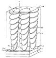
図1に本発明の光学フィルムの一例の断面模式図を示す。図1中、液晶分子LCはディスコティック液晶分子となっているが、これに限定されるものではない。
図1に示す光学フィルムは、ポリマーフィルム等からなる支持体1、配向膜2、及び光学異方性層3を有する。光学異方性層3中、液晶分子LCは、配向膜2との界面A近傍において、その円盤面と、配向膜2の表面とのなす角(チルト角)βaで配向している。また、光学異方性層3中、液晶分子LCは、空気界面Bの近傍において、その円盤面と、層面Bとのなす角(チルト角)βbで配向している。配向膜界面Aのチルト角βaと、空気界面Bのチルト角βbとは、βb<βa、の関係が成立していて、即ち、液晶分子LCは、逆ハイブリッド配向状態に固定されている。
逆ハイブリッド配向状態は、正ハイブリッド配向状態(βa<βb)よりも、液晶分子LCの配向乱れによるミクロ配向軸ズレを軽減できる。ミクロ配向軸ズレは、光学補償部材として液晶表示装置に用いた場合に、正面コントラストの低下の一因となる。本発明の光学フィルムは、正面コントラストを低下させることなく、光学補償に寄与するという利点がある。
FIG. 1 shows a schematic cross-sectional view of an example of the optical film of the present invention. In FIG. 1, the liquid crystal molecules LC are discotic liquid crystal molecules, but are not limited thereto.
The optical film shown in FIG. 1 has a
The reverse hybrid alignment state can reduce the micro-alignment misalignment due to the alignment disorder of the liquid crystal molecules LC than the normal hybrid alignment state (βa <βb). The micro-alignment axis misalignment causes a decrease in front contrast when used in a liquid crystal display device as an optical compensation member. The optical film of the present invention has an advantage that it contributes to optical compensation without lowering the front contrast.
図1に示す通り、配向膜2の表面にはラビング方向Rに沿って、ラビング処理が施されている。従来、配向膜のラビング処理面で液晶化合物の分子を配向させると、該分子は、ラビング方向に対して、円盤面を平行にして配向するのが一般的である。しかし、本発明では、所定の液晶化合物の分子を、所定の2種の添加剤の存在下で配向させているので、配向膜界面A近傍のディスコティック液晶分子LCは、その円盤面を、ラビング方向Rに対して直交にしてチルト角βaで配向している。その結果、光学異方性層の遅相軸Sは、ラビング方向Rに対して直交した方向に発現する。
連続生産においては、長尺のポリマーフィルムである支持体を搬送しつつ、長手方向にラビング処理が施される。即ち、ラビング方向Rは、搬送方向(フィルムの長手方向)と一致する。これに連続的に、光学異方性層を形成すると、本発明では、図1に示す通り、光学異方性層の遅相軸Sがラビング方向Rと直交する方向に発現する。その結果、長尺状の偏光膜と一体化する際に、長手方向を一致させたままで貼り合せることができる。従来の逆ハイブリッドでは、配向膜界面において、例えば、ディスコティック液晶分子が、円盤面をラビング方向に平行にして配向してしまうため、連続生産に適さず、実用化の弊害になっていたが、本発明ではかかる弊害を解決することができる。
As shown in FIG. 1, the surface of the
In continuous production, a rubbing treatment is performed in the longitudinal direction while conveying a support which is a long polymer film. That is, the rubbing direction R coincides with the transport direction (longitudinal direction of the film). When an optically anisotropic layer is formed continuously, the slow axis S of the optically anisotropic layer appears in a direction orthogonal to the rubbing direction R as shown in FIG. As a result, when integrating with a long polarizing film, it can be bonded while keeping the longitudinal direction coincident. In the conventional reverse hybrid, for example, the discotic liquid crystal molecules are aligned at the interface of the alignment film with the disk surface parallel to the rubbing direction. The present invention can solve such an adverse effect.
本発明の光学フィルムの一例では、配向膜界面における液晶分子のチルト角βaは、90〜70°(好ましくは90〜80°)であり;一方、空気界面におけるチルト角βbは、0〜30°(好ましくは0〜20°)である。それぞれの界面のチルト角が前記範囲である逆ハイブリッド配向は、TNモード液晶表示装置の視野角補償に適する。 In an example of the optical film of the present invention, the tilt angle βa of the liquid crystal molecules at the alignment film interface is 90 to 70 ° (preferably 90 to 80 °); on the other hand, the tilt angle βb at the air interface is 0 to 30 °. (Preferably 0 to 20 °). The reverse hybrid alignment in which the tilt angle of each interface is in the above range is suitable for viewing angle compensation of a TN mode liquid crystal display device.
図1に示す態様によれば、本発明の効果である光学異方性層と配向膜との密着性の改善効果が得られるとともに、従来の液晶化合物のハイブリッド配向状態を固定した光学異方性層の、ミクロな配向乱れ、それによって生じるミクロ配向軸ズレを軽減することができる。即ち、図1の態様によれば、密着性を改善できるとともに、液晶化合物のハイブリッド配向状態を固定した光学異方性層を有する光学フィルムに起因する正面コントラストの低下を軽減することができる。
但し、本発明は、図1に示す例に限定されるものではなく、例えば、液晶化合物の垂直配向状態を固定してなる光学異方性層を有する光学フィルム等であってもよい。
According to the embodiment shown in FIG. 1, the effect of improving the adhesion between the optically anisotropic layer and the alignment film, which is the effect of the present invention, is obtained, and the optical anisotropy in which the hybrid alignment state of the conventional liquid crystal compound is fixed. It is possible to reduce the micro-alignment disorder of the layer and the resulting micro-alignment misalignment. That is, according to the embodiment of FIG. 1, the adhesion can be improved, and the decrease in front contrast caused by the optical film having the optically anisotropic layer in which the hybrid alignment state of the liquid crystal compound is fixed can be reduced.
However, this invention is not limited to the example shown in FIG. 1, For example, the optical film etc. which have the optically anisotropic layer formed by fixing the vertical alignment state of a liquid crystal compound may be sufficient.
以下、本発明の光学フィルムの製造に用いられる材料及び製造方法について詳細に説明する。
(1)光学異方性層
本発明の光学フィルムは、液晶化合物を含む光学異方性層が、下記一般式(I)で表されるオニウム化合物の少なくとも1種を含むことを特徴とする。該オニウム化合物は、液晶化合物の配向膜界面における垂直配向を促進する垂直配向剤として作用するとともに、光学異方性層と配向膜との界面の密着性改善にも寄与する。前記光学異方性層は、また、必要に応じて、空気界面側の配向を制御する空気界面側配向制御剤(例えば、フルオロ脂肪族基を有する繰り返し単位を含む共重合体)を含有していてもよい。
Hereinafter, the material and manufacturing method used for manufacturing the optical film of the present invention will be described in detail.
(1) Optically anisotropic layer The optical film of the present invention is characterized in that the optically anisotropic layer containing a liquid crystal compound contains at least one onium compound represented by the following general formula (I). The onium compound acts as a vertical alignment agent for promoting vertical alignment at the alignment film interface of the liquid crystal compound, and also contributes to improving the adhesion at the interface between the optically anisotropic layer and the alignment film. The optically anisotropic layer also contains an air interface side orientation control agent (for example, a copolymer containing a repeating unit having a fluoroaliphatic group) for controlling the orientation on the air interface side, if necessary. May be.
(1)−1 垂直配向剤(一般式(I)で表されるオニウム化合物)
一般式(I)で表されるオニウム化合物は、液晶化合物の配向膜界面における配向を制御することを目的として添加され、液晶化合物の分子の配向膜界面近傍におけるチルト角を増加させる作用がある。
(1) -1 Vertical alignment agent (onium compound represented by general formula (I))
The onium compound represented by the general formula (I) is added for the purpose of controlling the alignment of the liquid crystal compound at the alignment film interface, and has the effect of increasing the tilt angle in the vicinity of the alignment film interface of the molecules of the liquid crystal compound.
一般式(I)中、環Aは含窒素複素環からなる第4級アンモニウムイオンを表し、Xはアニオンを表し;L1は二価の連結基を表し;L2は単結合又は二価の連結基を表し;Y1は5又は6員環を部分構造として有する2価の連結基を表し;Zは2〜20のアルキレン基を部分構造として有する2価の連結基を表し;P1及びP2はそれぞれ独立に重合性エチレン性不飽和基を有する一価の置換基を表す。 In general formula (I), ring A represents a quaternary ammonium ion composed of a nitrogen-containing heterocycle, X represents an anion; L 1 represents a divalent linking group; L 2 represents a single bond or a divalent group. Y 1 represents a divalent linking group having a 5- or 6-membered ring as a partial structure; Z represents a divalent linking group having 2 to 20 alkylene groups as a partial structure; P 1 and P 2 independently represents a monovalent substituent having a polymerizable ethylenically unsaturated group.
環Aは含窒素複素環からなる第4級アンモニウムイオンを表す。環Aの例としては、ピリジン環、ピコリン環、2,2’−ビピリジル環、4,4’−ビピリジル環、1,10−フェナントロリン環、キノリン環、オキサゾール環、チアゾール環、イミダゾール環、ピラジン環、トリアゾール環、テトラゾール環などが挙げられ、好ましくは第4級イミダゾリウムイオン、及び第4級ピリジニウムイオンである。 Ring A represents a quaternary ammonium ion composed of a nitrogen-containing heterocyclic ring. Examples of ring A include pyridine ring, picoline ring, 2,2′-bipyridyl ring, 4,4′-bipyridyl ring, 1,10-phenanthroline ring, quinoline ring, oxazole ring, thiazole ring, imidazole ring, pyrazine ring , Triazole ring, tetrazole ring and the like, preferably quaternary imidazolium ion and quaternary pyridinium ion.
Xは、アニオンを表す。Xの例としては、ハロゲン陰イオン(例えば、フッ素イオン、塩素イオン、臭素イオン、ヨウ素イオンなど)、スルホネートイオン(例えば、メタンスルホン酸イオン、トリフルオロメタンスルホン酸イオン、メチル硫酸イオン、ビニルスルホン酸イオン、アリルスルホン酸イオン、p−トルエンスルホン酸イオン、p−クロロベンゼンスルホン酸イオン、p−ビニルベンゼンスルホン酸イオン、1,3−ベンゼンジスルホン酸イオン、1,5−ナフタレンジスルホン酸イオン、2,6−ナフタレンジスルホン酸イオンなど)、硫酸イオン、炭酸イオン、硝酸イオン、チオシアン酸イオン、過塩素酸イオン、テトラフルオロほう酸イオン、ピクリン酸イオン、酢酸イオン、安息香酸イオン、p−ビニル安息香酸イオン、ギ酸イオン、トリフルオロ酢酸イオン、リン酸イオン(例えば、ヘキサフルオロリン酸イオン)、水酸化物イオンなどが挙げられる。好ましくは、ハロゲン陰イオン、スルホネートイオン、水酸化物イオンである。また、特に塩素イオン、臭素イオン、ヨウ素イオン、メタンスルホン酸イオン、ビニルスルホン酸イオン、p−トルエンスルホン酸イオン、p−ビニルベンゼンスルホン酸イオンが好ましい。 X represents an anion. Examples of X include a halogen anion (for example, fluorine ion, chlorine ion, bromine ion, iodine ion, etc.), sulfonate ion (for example, methanesulfonate ion, trifluoromethanesulfonate ion, methylsulfate ion, vinylsulfonate ion) , Allyl sulfonate ion, p-toluene sulfonate ion, p-chlorobenzene sulfonate ion, p-vinylbenzene sulfonate ion, 1,3-benzene disulfonate ion, 1,5-naphthalene disulfonate ion, 2,6- Naphthalenedisulfonate ion), sulfate ion, carbonate ion, nitrate ion, thiocyanate ion, perchlorate ion, tetrafluoroborate ion, picrate ion, acetate ion, benzoate ion, p-vinylbenzoate ion, formate ion The trifle B acetate ion, phosphoric acid ion (e.g., hexafluorophosphate ion), such as a hydroxide ion. Preferred are halogen anions, sulfonate ions, and hydroxide ions. In particular, chlorine ion, bromine ion, iodine ion, methanesulfonic acid ion, vinylsulfonic acid ion, p-toluenesulfonic acid ion, and p-vinylbenzenesulfonic acid ion are preferable.
L1は、二価の連結基を表す。L1の例としては、アルキレン基、−O−、−S−、−CO−、−SO2−、−NRa−(但し、Raは炭素原子数が1〜5のアルキル基又は水素原子である)、アルケニレン基、アルキニレン基またはアリーレン基との組み合わせからなる炭素原子数が1〜20の二価の連結基が挙げられる。L1は、炭素原子数が1〜10の−AL−、−O−AL−、−CO−O−AL−、−O−CO−AL−が好ましく、炭素原子数が1〜10の−AL−、−O−AL−がさらに好ましく、炭素原子数が1〜5の−AL−、−O−AL−が最も好ましい。なお、ALはアルキレン基を表す。 L 1 represents a divalent linking group. Examples of L 1 include an alkylene group, —O—, —S—, —CO—, —SO 2 —, —NRa— (where Ra is an alkyl group having 1 to 5 carbon atoms or a hydrogen atom. ), A divalent linking group having 1 to 20 carbon atoms, which is a combination with an alkenylene group, an alkynylene group or an arylene group. L 1 is preferably -AL-, -O-AL-, -CO-O-AL-, or -O-CO-AL- having 1 to 10 carbon atoms, and -AL having 1 to 10 carbon atoms. -And -O-AL- are more preferable, and -AL- and -O-AL- having 1 to 5 carbon atoms are most preferable. AL represents an alkylene group.
L2は、単結合又は二価の連結基を表す。L2の例としては、アルキレン基、−O−、−S−、−CO−、−SO2−、−NRa−(但し、Raは炭素原子数が1〜5のアルキル基又は水素原子である)、アルケニレン基、アルキニレン基またはアリーレン基との組み合わせからなる炭素原子数が1〜10の二価の連結基、単結合、−O−、−O−CO−、−CO−O−、−O−AL−O−、−O−AL−O−CO−、−O−AL−CO−O−、−CO−O−AL−O−、−CO−O−AL−O−CO−、−CO−O−AL−CO−O−、−O−CO−AL−O−、−O−CO−AL−O−CO−、−O−CO−AL−CO−O−などが挙げられる。なお、ALはアルキレン基を表す。L2は、単結合、炭素原子数が1〜10の−AL−、−O−AL−、−NRa−AL−O−が好ましく、単結合、炭素原子数が1〜5の−AL−、−O−AL−、−NRa−AL−O−がさらに好ましく、単結合、炭素原子数が1〜5の−O−AL−、−NRa−AL−O−が最も好ましい。 L 2 represents a single bond or a divalent linking group. Examples of L 2 include an alkylene group, —O—, —S—, —CO—, —SO 2 —, —NRa— (where Ra is an alkyl group having 1 to 5 carbon atoms or a hydrogen atom. ), A divalent linking group having 1 to 10 carbon atoms consisting of a combination with an alkenylene group, an alkynylene group or an arylene group, a single bond, —O—, —O—CO—, —CO—O—, —O -AL-O-, -O-AL-O-CO-, -O-AL-CO-O-, -CO-O-AL-O-, -CO-O-AL-O-CO-, -CO -O-AL-CO-O-, -O-CO-AL-O-, -O-CO-AL-O-CO-, -O-CO-AL-CO-O-, and the like can be given. AL represents an alkylene group. L 2 is preferably a single bond, -AL- having 1 to 10 carbon atoms, -O-AL-, or -NRa-AL-O-, a single bond, -AL- having 1 to 5 carbon atoms, —O—AL— and —NRa—AL—O— are more preferable, and —O—AL— and —NRa—AL—O— having a single bond and 1 to 5 carbon atoms are most preferable.
Y1は、5又は6員環を部分構造として有する2価の連結基を表す。Y1の例としては、シクロヘキシル環、芳香族環または複素環などが挙げられる。芳香族環としては、例えば、ベンゼン環、インデン環、ナフタレン環、フルオレン環、フェナントレン環、アントラセン環、ビフェニル環、ピレン環などが挙げられ、ベンゼン環、ビフェニル環、ナフタレン環が特に好ましい。複素環を構成する複素原子としては、窒素原子、酸素原子および硫黄原子が好ましく、例えば、フラン環、チオフェン環、ピロール環、ピロリン環、ピロリジン環、オキサゾール環、イソオキサゾール環、チアゾール環、イソチアゾール環、イミダゾール環、イミダゾリン環、イミダゾリジン環、ピラゾール環、ピラゾリン環、ピラゾリジン環、トリアゾール環、フラザン環、テトラゾール環、ピラン環、ジオキサン環、ジチアン環、チイン環、ピリジン環、ピペリジン環、オキサジン環、モルホリン環、チアジン環、ピリダジン環、ピリミジン環、ピラジン環、ピペラジン環およびトリアジン環などが挙げられる。複素環は6員環であることが好ましい。Y1で表される5又は6員環を部分構造として有する2価の連結基はさらに置換基を有していてもよい。 Y 1 represents a divalent linking group having a 5- or 6-membered ring as a partial structure. Examples of Y 1 include a cyclohexyl ring, an aromatic ring or a heterocyclic ring. Examples of the aromatic ring include a benzene ring, an indene ring, a naphthalene ring, a fluorene ring, a phenanthrene ring, an anthracene ring, a biphenyl ring, and a pyrene ring, and a benzene ring, a biphenyl ring, and a naphthalene ring are particularly preferable. The hetero atom constituting the hetero ring is preferably a nitrogen atom, an oxygen atom or a sulfur atom. For example, a furan ring, thiophene ring, pyrrole ring, pyrroline ring, pyrrolidine ring, oxazole ring, isoxazole ring, thiazole ring, isothiazole Ring, imidazole ring, imidazoline ring, imidazolidine ring, pyrazole ring, pyrazoline ring, pyrazolidine ring, triazole ring, furazane ring, tetrazole ring, pyran ring, dioxane ring, dithiane ring, thiine ring, pyridine ring, piperidine ring, oxazine ring Morpholine ring, thiazine ring, pyridazine ring, pyrimidine ring, pyrazine ring, piperazine ring and triazine ring. The heterocycle is preferably a 6-membered ring. The divalent linking group having a 5- or 6-membered ring represented by Y 1 as a partial structure may further have a substituent.
置換基の例としては、ハロゲン原子、シアノ基、炭素原子数が1〜12(より好ましくは1〜10、さらに好ましくは1〜5)のアルキル基、炭素原子数が2〜12(より好ましくは2〜10、さらに好ましくは2〜5)のアルケニル基、炭素原子数が1〜12(より好ましくは1〜10、さらに好ましくは1〜5)のアルコキシ基などが挙げられる。アルキル基およびアルコキシ基は、炭素原子数が2〜12(より好ましくは2〜10、さらに好ましくは2〜5)のアシル基または炭素原子数が2〜12(より好ましくは2〜10、さらに好ましくは2〜5)のアシルオキシ基で置換されていてもよい。アシル基は−CO−R、アシルオキシ基は−O−CO−Rで表され、Rは脂肪族基(アルキル基、置換アルキル基、アルケニル基、置換アルケニル基、アルキニル基、置換アルキニル基)または芳香族基(アリール基、置換アリール基)である。Rは、脂肪族基であることが好ましく、アルキル基またはアルケニル基であることがさらに好ましい。 Examples of the substituent include a halogen atom, a cyano group, an alkyl group having 1 to 12 carbon atoms (more preferably 1 to 10, more preferably 1 to 5), and 2 to 12 carbon atoms (more preferably). An alkenyl group having 2 to 10 and more preferably 2 to 5), an alkoxy group having 1 to 12 carbon atoms (more preferably 1 to 10, more preferably 1 to 5), and the like can be mentioned. The alkyl group and the alkoxy group have an acyl group having 2 to 12 carbon atoms (more preferably 2 to 10 and more preferably 2 to 5) or 2 to 12 carbon atoms (more preferably 2 to 10 and more preferably). May be substituted with an acyloxy group of 2-5). The acyl group is represented by —CO—R, the acyloxy group is represented by —O—CO—R, and R is an aliphatic group (alkyl group, substituted alkyl group, alkenyl group, substituted alkenyl group, alkynyl group, substituted alkynyl group) or aromatic. Group (aryl group, substituted aryl group). R is preferably an aliphatic group, and more preferably an alkyl group or an alkenyl group.
Y1で表される2価の連結基は、5又は6員環を2以上有する2価の連結基であるのが好ましく、2以上の環が、連結基で連結された構造を有するのがより好ましい。連結基の例については、L1及びL2が表す連結基の例や−C≡C−、−CH=CH−、−CH=N−、−N=CH−、−N=N−などが挙げられる。 The divalent linking group represented by Y 1 is preferably a divalent linking group having two or more 5- or 6-membered rings, and preferably has a structure in which two or more rings are connected by a linking group. More preferred. Examples of linking groups include linking groups represented by L 1 and L 2, and —C≡C—, —CH═CH—, —CH═N—, —N═CH—, —N═N— and the like. Can be mentioned.
Zは、炭素原子数2〜20のアルキレン基を部分構造として有し、−O−、−S−、−CO−、−SO2−との組み合わせからなる2価の連結基を表し、アルキレン基は置換基を有していてもよい。前記2価の連結基の例としては、アルキレンオキシ基、ポリアルキレンオキシ基が挙げられる。Zが表すアルキレン基の炭素原子数は、2〜16であるのがより好ましく、2〜12であるのがさらに好ましく、2〜8であるのが特に好ましい。 Z represents a divalent linking group having a combination of —O—, —S—, —CO—, and —SO 2 — with a C 2-20 alkylene group as a partial structure, and an alkylene group May have a substituent. Examples of the divalent linking group include an alkyleneoxy group and a polyalkyleneoxy group. The number of carbon atoms of the alkylene group represented by Z is more preferably 2 to 16, more preferably 2 to 12, and particularly preferably 2 to 8.
P1及びP2は、それぞれ独立に重合性エチレン性不飽和基を有する一価の置換基を表す。前記重合性エチレン性不飽和基を有する一価の置換基の例としては、下記の式(M−1)〜(M−8)が挙げられる。即ち、重合性エチレン性不飽和基を有する一価の置換基は、(M−8)のように、エテニル基のみからなる置換基であってもよい。 P 1 and P 2 each independently represent a monovalent substituent having a polymerizable ethylenically unsaturated group. Examples of the monovalent substituent having the polymerizable ethylenically unsaturated group include the following formulas (M-1) to (M-8). That is, the monovalent substituent having a polymerizable ethylenically unsaturated group may be a substituent consisting only of an ethenyl group as in (M-8).
式(M−3)、(M−4)中、Rは水素原子またはアルキル基を表し、水素原子またはメチル基が好ましい。上記式(M−1)〜(M−8)の中、(M−1)、(M−2)、(M−8)が好ましく、(M−1)又は(M−8)がより好ましい。特に、P1としては(M−1)が好ましい。またP2としては、(M−1)又は(M−8)が好ましく、環Aが第4級イミダゾリウムイオンである化合物では、P2は(M−8)又は(M−1)であるのが好ましく、及び環Aが第4級ピリジニウムイオンである化合物では、P2は(M−1)であるのが好ましい。 In formulas (M-3) and (M-4), R represents a hydrogen atom or an alkyl group, preferably a hydrogen atom or a methyl group. Among the above formulas (M-1) to (M-8), (M-1), (M-2) and (M-8) are preferable, and (M-1) or (M-8) is more preferable. . In particular, (M-1) is preferable as P 1 . P 2 is preferably (M-1) or (M-8), and in the compound in which ring A is a quaternary imidazolium ion, P 2 is (M-8) or (M-1). And in compounds where ring A is a quaternary pyridinium ion, P 2 is preferably (M-1).
一般式(I)で表されるオニウム化合物は、下記一般式(I−1)及び(I−2)で表されるオニウム化合物が含まれる。
L3は、二価の連結基を表し、L3の例としては、単結合、−O−、−O−CO−、−CO−O−、−O−AL−O−、−O−AL−O−CO−、−O−AL−CO−O−、−CO−O−AL−O−、−CO−O−AL−O−CO−、−CO−O−AL−CO−O−、−O−CO−AL−O−、−O−CO−AL−O−CO−、−O−CO−AL−CO−O−である。なお、ALは、炭素原子数が1〜10のアルキレン基を表す。L3は、単結合、−O−、−O−AL−O−、−O−AL−O−CO−、−O−AL−CO−O−、−CO−O−AL−O−、−CO−O−AL−O−CO−、−CO−O−AL−CO−O−、−O−CO−AL−O−、−O−CO−AL−O−CO−、−O−CO−AL−CO−O−が好ましく、単結合または−O−がさらに好ましく、−O−が最も好ましい。 L 3 represents a divalent linking group, and examples of L 3 include a single bond, —O—, —O—CO—, —CO—O—, —O—AL—O—, —O—AL. -O-CO-, -O-AL-CO-O-, -CO-O-AL-O-, -CO-O-AL-O-CO-, -CO-O-AL-CO-O-, -O-CO-AL-O-, -O-CO-AL-O-CO-, and -O-CO-AL-CO-O-. Note that AL represents an alkylene group having 1 to 10 carbon atoms. L 3 represents a single bond, —O—, —O—AL—O—, —O—AL—O—CO—, —O—AL—CO—O—, —CO—O—AL—O—, — CO-O-AL-O-CO-, -CO-O-AL-CO-O-, -O-CO-AL-O-, -O-CO-AL-O-CO-, -O-CO- AL-CO-O- is preferable, a single bond or -O- is more preferable, and -O- is most preferable.
L4は、二価の連結基を表し、L4の例としては、単結合、−O−、−O−CO−、−CO−O−、−C≡C−、−CH=CH−、−CH=N−、−N=CH−、−N=N−、−NH−CO−、−CO−NH−である。L4は、単結合、−O−CO−、−CO−O−、−C≡C−、−NH−CO−、−CO−NH−が好ましく、単結合、−O−CO−、−CO−O−がさらに好ましく、−O−CO−、−CO−O−が最も好ましい。 L 4 represents a divalent linking group, and examples of L 4 include a single bond, —O—, —O—CO—, —CO—O—, —C≡C—, —CH═CH—, -CH = N-, -N = CH-, -N = N-, -NH-CO-, -CO-NH-. L 4 is preferably a single bond, —O—CO—, —CO—O—, —C≡C—, —NH—CO—, —CO—NH—, and preferably a single bond, —O—CO—, —CO. —O— is more preferable, and —O—CO— and —CO—O— are most preferable.
Y2及びY3はそれぞれ独立に置換基を有していてもよい6員環を表し、6員環は、脂肪族環、芳香族環(ベンゼン環)および複素環を含む。脂肪族6員環の例としては、シクロヘキサン環、シクロヘキセン環およびシクロヘキサジエン環などが挙げられる。芳香族環の例としては、ベンゼン環、インデン環、ナフタレン環、フルオレン環、フェナントレン環、アントラセン環、ビフェニル環、ピレン環などが挙げられる。6員複素環の例としては、ピラン環、ジオキサン環、ジチアン環、チイン環、ピリジン環、ピペリジン環、オキサジン環、モルホリン環、チアジン環、ピリダジン環、ピリミジン環、ピラジン環、ピペラジン環、トリアジン環などが挙げられる。また、6員環に他の6員環または5員環が縮合していてもよい。Y2及びY3は、シクロヘキサン環、ピリジン環、ピリミジン環、ベンゼン環が好ましく、ピリミジン環、ベンゼン環がさらに好ましく、ベンゼン環が最も好ましい。 Y 2 and Y 3 each independently represent a 6-membered ring optionally having a substituent, and the 6-membered ring includes an aliphatic ring, an aromatic ring (benzene ring) and a heterocyclic ring. Examples of the aliphatic 6-membered ring include a cyclohexane ring, a cyclohexene ring, and a cyclohexadiene ring. Examples of the aromatic ring include a benzene ring, an indene ring, a naphthalene ring, a fluorene ring, a phenanthrene ring, an anthracene ring, a biphenyl ring, and a pyrene ring. Examples of 6-membered heterocycles include pyran ring, dioxane ring, dithiane ring, thiine ring, pyridine ring, piperidine ring, oxazine ring, morpholine ring, thiazine ring, pyridazine ring, pyrimidine ring, pyrazine ring, piperazine ring, triazine ring Etc. Further, another 6-membered ring or a 5-membered ring may be condensed with the 6-membered ring. Y 2 and Y 3 are preferably a cyclohexane ring, a pyridine ring, a pyrimidine ring or a benzene ring, more preferably a pyrimidine ring or a benzene ring, and most preferably a benzene ring.
置換基の例としては、ハロゲン原子、シアノ基、炭素原子数が1〜12(より好ましくは1〜10、さらに好ましくは1〜5)のアルキル基、炭素原子数が1〜12のアルコキシ基などが挙げられる。アルキル基およびアルコキシ基は、炭素原子数が2〜12のアシル基または炭素原子数が2〜12のアシルオキシ基で置換されていてもよい。アシル基は−CO−R、アシルオキシ基は−O−CO−Rで表され、Rは脂肪族基(アルキル基、置換アルキル基、アルケニル基、置換アルケニル基、アルキニル基、置換アルキニル基)または芳香族基(アリール基、置換アリール基)である。Rは、脂肪族基であることが好ましく、アルキル基またはアルケニル基であることがさらに好ましい。
式(I−1)及び(I−2)中、少なくとも1つのY3は、置換されたベンゼン環であるのが好ましく、1以上のハロゲン基、アルキル基又はアルコキシ基を有するベンゼン環であるのがより好ましく、2以上のアルキル基又はアルケニル基を有するベンゼン環であるのがさらに好ましい。
Examples of the substituent include a halogen atom, a cyano group, an alkyl group having 1 to 12 carbon atoms (more preferably 1 to 10, more preferably 1 to 5), an alkoxy group having 1 to 12 carbon atoms, and the like. Is mentioned. The alkyl group and the alkoxy group may be substituted with an acyl group having 2 to 12 carbon atoms or an acyloxy group having 2 to 12 carbon atoms. The acyl group is represented by —CO—R, the acyloxy group is represented by —O—CO—R, and R is an aliphatic group (alkyl group, substituted alkyl group, alkenyl group, substituted alkenyl group, alkynyl group, substituted alkynyl group) or aromatic. Group (aryl group, substituted aryl group). R is preferably an aliphatic group, and more preferably an alkyl group or an alkenyl group.
In formulas (I-1) and (I-2), at least one Y 3 is preferably a substituted benzene ring, preferably a benzene ring having one or more halogen groups, alkyl groups or alkoxy groups. Is more preferable, and a benzene ring having two or more alkyl groups or alkenyl groups is more preferable.
mは1又は2の整数を表し、mが2の場合、二つのL4及び二つのY3は、異なっていてもよい。 m represents an integer of 1 or 2, and when m is 2, two L 4 and two Y 3 may be different.
CpH2pは、分岐構造を有していてもよい鎖状アルキレン基を表す。CpH2pは、直鎖状アルキレン基(−(CH2)p−)であることが好ましい。 C p H 2p represents a chain alkylene group which may have a branched structure. C p H 2p is preferably a linear alkylene group (— (CH 2 ) p —).
pは、1〜10の整数を表し、1〜5であることがさらに好ましく、1〜2であることが最も好ましい。 p represents an integer of 1 to 10, more preferably 1 to 5, and most preferably 1 to 2.
一般式(I)で表されるオニウム化合物は、下記一般式(I−3)及び(I−4)で表されるオニウム化合物が含まれる。
一般式(I−3)及び(I−4)の各記号の定義は、一般式(I−1)又は(I−2)中のそれぞれと同義であり;R’は、置換基を表し;bは、1〜4の整数を表す。 The definition of each symbol of general formula (I-3) and (I-4) is synonymous with each in general formula (I-1) or (I-2); R 'represents a substituent; b represents an integer of 1 to 4.
R’の例は、一般式(I−1)又は(I−2)中のY2及びY3で表される6員環が有する置換基の例と同様であり、好ましい範囲も同様である。即ち、R’はハロゲン基、アルキル基又はアルコキシ基であるのが好ましい。
bは、1〜4の整数を表し、1〜3であることがより好ましく、2〜3であることがさらに好ましい。
Examples of R ′ are the same as the examples of the substituent of the 6-membered ring represented by Y 2 and Y 3 in general formula (I-1) or (I-2), and the preferred ranges are also the same. . That is, R ′ is preferably a halogen group, an alkyl group or an alkoxy group.
b represents an integer of 1 to 4, more preferably 1 to 3, and still more preferably 2 to 3.
以下に、一般式(I)で表される化合物の具体例を示す。 Specific examples of the compound represented by the general formula (I) are shown below.
一般式(I)のオニウム化合物は、一般に含窒素ヘテロ環をアルキル化(メンシュトキン反応)することで合成することができる。 The onium compound of the general formula (I) can be generally synthesized by alkylating a nitrogen-containing heterocycle (Menstokin reaction).
(1)−2 液晶化合物
光学異方性層には、液晶化合物が含まれる。
前記光学異方性層の形成に用いられる液晶化合物は、棒状液晶性化合物であっても、ディスコティック液晶化合物であってもよい。中でも、ディスコティック液晶化合物が好ましく、トリフェニレン化合物、及びベンゼンの1、3及び5位が置換された3置換ベンゼン化合物が好ましく、特に、例えば、以下の式(X)を円盤状コアとして有する3置換ベンゼン化合物が好ましい。
(1) -2 Liquid crystal compound The optically anisotropic layer contains a liquid crystal compound.
The liquid crystal compound used for forming the optically anisotropic layer may be a rod-like liquid crystal compound or a discotic liquid crystal compound. Among them, a discotic liquid crystal compound is preferable, a triphenylene compound, and a 3-substituted benzene compound in which 1, 3, and 5 positions of benzene are substituted are preferable, and particularly, for example, a tri-substituted compound having the following formula (X) as a discotic core Benzene compounds are preferred.
式(X)中、Rはそれぞれ式(X)の化合物が液晶性を示すために必要な有機置換基を表し、式(1)のR1、R2及びR3と同義である。 In formula (X), R represents an organic substituent necessary for the compound of formula (X) to exhibit liquid crystallinity, and has the same meaning as R 1 , R 2 and R 3 in formula (1).
式(X)で表されるディスコティック液晶化合物は、高いΔn及び低い波長分散性を示すので、当該化合物の分子の配向を固定して形成された光学異方性層を有する光学フィルムは、液晶表示装置の光学補償フィルムとしての有用性が高い。中でも、式(X)のディスコティック液晶化合物の分子を、「垂直配向」や「逆ハイブリッド配向」に固定して形成された光学異方性層を有する光学フィルムは、液晶表示装置の光学補償フィルムとしての有用性が特に高い。 Since the discotic liquid crystal compound represented by the formula (X) exhibits high Δn and low wavelength dispersion, an optical film having an optically anisotropic layer formed by fixing the molecular orientation of the compound is a liquid crystal. It is highly useful as an optical compensation film for display devices. Among them, an optical film having an optically anisotropic layer formed by fixing molecules of the discotic liquid crystal compound of formula (X) to “vertical alignment” or “reverse hybrid alignment” is an optical compensation film for liquid crystal display devices. Especially useful as.
前記式(X)の化合物については、特開2002−90545号公報、特開2006−276203号公報、及び特願2009−68293号の明細書に詳細な記載があり、具体例についても同様である。 The compound of formula (X) is described in detail in JP-A-2002-90545, JP-A-2006-276203, and Japanese Patent Application No. 2009-68293, and the same applies to specific examples. .
ディスコティック液晶性化合物は、重合により固定可能なように、重合性基を有するのが好ましい。例えば、ディスコティック液晶性化合物の円盤状コアに、置換基として重合性基を結合させた構造が考えられるが、但し、円盤状コアに重合性基を直結させると、重合反応において配向状態を保つことが困難になる。そこで、円盤状コアと重合性基との間に連結基を有する構造が好ましい。即ち、重合性基を有するディスコティック液晶性化合物は、下記式(II)で表される化合物であることが好ましい。 The discotic liquid crystalline compound preferably has a polymerizable group so that it can be fixed by polymerization. For example, a structure in which a polymerizable group is bonded as a substituent to a discotic core of a discotic liquid crystalline compound is conceivable. However, when a polymerizable group is directly connected to the discotic core, the alignment state is maintained in the polymerization reaction. It becomes difficult. Therefore, a structure having a linking group between the discotic core and the polymerizable group is preferable. That is, the discotic liquid crystalline compound having a polymerizable group is preferably a compound represented by the following formula (II).
式中、Y11、Y12及びY13は、それぞれ独立に置換されていてもよいメチン又は窒素原子を表し;L1、L2及びL3は、それぞれ独立に単結合又は二価の連結基を表し;H1、H2及びH3は、それぞれ独立に一般式(I−A)又は(I−B)の基を表し;R1、R2及びR3は、それぞれ独立に下記一般式(I−R)を表す; In the formula, Y 11 , Y 12 and Y 13 each independently represent a methine or nitrogen atom which may be substituted; L 1 , L 2 and L 3 each independently represent a single bond or a divalent linking group. H 1 , H 2 and H 3 each independently represent a group of the general formula (IA) or (IB); R 1 , R 2 and R 3 each independently represent the following general formula Represents (IR);
一般式(I−A)中、YA1及びYA2は、それぞれ独立にメチン又は窒素原子を表し;XAは、酸素原子、硫黄原子、メチレン又はイミノを表し;*は上記一般式(1)におけるL1〜L3側と結合する位置を表し;**は上記一般式(1)におけるR1〜R3側と結合する位置を表す; In the general formula (IA), YA 1 and YA 2 each independently represents a methine or nitrogen atom; XA represents an oxygen atom, a sulfur atom, methylene or imino; * represents the above general formula (1) Represents a position bonded to the L 1 to L 3 side; ** represents a position bonded to the R 1 to R 3 side in the general formula (1);
一般式(I−B)中、YB1及びYB2は、それぞれ独立にメチン又は窒素原子を表し;XBは、酸素原子、硫黄原子、メチレン又はイミノを表し;*は上記一般式(1)におけるL1〜L3側と結合する位置を表し;**は上記一般式(1)におけるR1〜R3側と結合する位置を表す; In the general formula (IB), YB 1 and YB 2 each independently represent a methine or nitrogen atom; XB represents an oxygen atom, a sulfur atom, methylene or imino; * represents the above general formula (1) Represents a position bonded to the L 1 to L 3 side; ** represents a position bonded to the R 1 to R 3 side in the general formula (1);
一般式(I−R)
*−(−L21−Q2)n1−L22−L23−Q1
一般式(I−R)中、*は、一般式(1)におけるH1〜H3側と結合する位置を表す;L21は単結合又は二価の連結基を表す;Q2は少なくとも1種類の環状構造を有する二価の基(環状基)を表す;n1は、0〜4の整数を表す;L22は、**−O−、**−O−CO−、**−CO−O−、**−O−CO−O−、**−S−、**−NH−、**−SO2−、**−CH2−、**−CH=CH−又は**−C≡C−を表す;L23は、−O−、−S−、−C(=O)−、−SO2−、−NH−、−CH2−、−CH=CH−及び−C≡C−並びにこれらの組み合わせからなる群より選ばれる二価の連結基を表す;Q1は重合性基又は水素原子を表す。
General formula (IR)
*-(-L 21 -Q 2 ) n1 -L 22 -L 23 -Q 1
In the general formula (IR), * represents a position bonded to the H 1 to H 3 side in the general formula (1); L 21 represents a single bond or a divalent linking group; Q 2 is at least 1 It represents the type of divalent group having a cyclic structure (cyclic group); n1 represents an integer of 0 to 4; L 22 is, ** - O -, ** - O-CO -, ** - CO -O -, ** - O-CO -O -, ** - S -, ** - NH -, ** - SO 2 -, ** - CH 2 -, ** - CH = CH- or ** —C≡C—; L 23 represents —O—, —S—, —C (═O) —, —SO 2 —, —NH—, —CH 2 —, —CH═CH— and —C. Represents a divalent linking group selected from the group consisting of ≡C— and combinations thereof; Q 1 represents a polymerizable group or a hydrogen atom;
前記式(II)で表される3置換ベンゼン系ディスコティック液晶性化合物の各符号の好ましい範囲、及び前記式(II)の化合物の具体例については、特開2010−244038号公報の段落[0013]〜[0077]、特開2006-76992号公報の[0052]の[化13]〜[化43]、特開2007−2220号公報の[0040]の[化13]〜[0063]の[化36]の記載を参照することができる。但し、本発明に使用可能なディスコティック液晶性化合物は、前記式(II)の3置換ベンゼン系ディスコティック液晶性化合物に限定されるものではない。 For preferred ranges of the respective symbols of the trisubstituted benzene-based discotic liquid crystalline compound represented by the formula (II) and specific examples of the compound of the formula (II), refer to paragraph [0013] of JP 2010-244038 A. ] To [0077], [Chemical 13] to [Chemical 43] of [0052] of JP-A-2006-76992, and [Chemical 13] to [0063] of [0040] of JP-A-2007-2220. The description of Chemical Formula 36] can be referred to. However, the discotic liquid crystalline compound that can be used in the present invention is not limited to the trisubstituted benzene-based discotic liquid crystalline compound of the formula (II).
また、ディスコティック液晶化合物の例にはトリフェニレン化合物が含まれ、トリフェニレン化合物としては、特開2007−108732号公報の段落[0062]〜[0067]に記載の化合物等が挙げられるが、本発明はこれらに限定されるものではない。 Examples of the discotic liquid crystal compound include a triphenylene compound, and examples of the triphenylene compound include the compounds described in paragraphs [0062] to [0067] of JP-A-2007-108732. It is not limited to these.
また、ディスコティック液晶化合物の例にはベンゼンの1、3位が置換された2置換ベンゼン化合物が含まれ、2置換ベンゼン化合物としては、特願2009−68293号の段落[0020]〜[0064]に記載の化合物等が挙げられるが、本発明はこれらに限定されるものではない。 Examples of the discotic liquid crystal compound include a disubstituted benzene compound substituted at the 1,3-position of benzene. Examples of the disubstituted benzene compound include paragraphs [0020] to [0064] of Japanese Patent Application No. 2009-68293. However, the present invention is not limited to these.
その他、本発明に利用可能なディスコティック化合物の例には、ベンゼン誘導体(C.Destradeらの研究報告、Mol.Cryst.71巻、111頁(1981年)に記載)、トルキセン誘導体(C.Destradeらの研究報告、Mol.Cryst.122巻、141頁(1985年)、Physics lett,A,78巻、82頁(1990)に記載)、シクロヘキサン誘導体(B.Kohneらの研究報告、Angew.Chem.96巻、70頁(1984年)に記載)及びアザクラウン系又はフェニルアセチレン系のマクロサイクル(J.M.Lehnらの研究報告、J.Chem.Commun.,1794頁(1985年)、J.Zhangらの研究報告、J.Am.Chem.Soc.116巻、2655頁(1994年)記載)が含まれる。 Other examples of discotic compounds that can be used in the present invention include benzene derivatives (described in the research report of C. Destrade et al., Mol. Cryst. 71, 111 (1981)), and truxene derivatives (C. Destrade). Et al., Mol. Cryst. 122, 141 (1985), Physics lett, A, 78, 82 (1990)), cyclohexane derivatives (B. Kohne et al., Angew. Chem. 96, 70 (1984)) and azacrown or phenylacetylene macrocycles (J.M. Lehn et al., J. Chem. Commun., 1794 (1985), J. Zhang et al., J. Am. Chem. Soc., 116, 265 Page (1994) described) are included.
また、光学異方性層の形成に利用可能な棒状液晶性化合物としては、アゾメチン類、アゾキシ類、シアノビフェニル類、シアノフェニルエステル類、安息香酸エステル類、シクロヘキサンカルボン酸フェニルエステル類、シアノフェニルシクロヘキサン類、シアノ置換フェニルピリミジン類、アルコキシ置換フェニルピリミジン類、フェニルジオキサン類、トラン類及びアルケニルシクロヘキシルベンゾニトリル類が好ましく用いられる。以上のような低分子液晶性化合物だけではなく、高分子液晶性化合物も用いることができる。棒状液晶性化合物を重合によって配向を固定することがより好ましい。液晶性化合物には活性光線や電子線、熱などによって重合や架橋反応を起こしうる部分構造を有するものが好適に用いられる。その部分構造の個数は好ましくは1〜6個、より好ましくは1〜3個である。重合性棒状液晶性化合物としては、Makromol.Chem.,190巻、2255頁(1989年)、Advanced Materials 5巻、107頁(1993年)、米国特許第4683327号明細書、同5622648号明細書、同5770107号明細書、国際公開WO95/22586号公報、同95/24455号公報、同97/00600号公報、同98/23580号公報、同98/52905号公報、特開平1−272551号公報、同6−16616号公報、同7−110469号公報、同11−80081号公報、及び特開2001−328973号公報などに記載の化合物を用いることができる。 Examples of rod-like liquid crystalline compounds that can be used for forming the optically anisotropic layer include azomethines, azoxys, cyanobiphenyls, cyanophenyl esters, benzoic acid esters, cyclohexanecarboxylic acid phenyl esters, cyanophenylcyclohexane. , Cyano-substituted phenylpyrimidines, alkoxy-substituted phenylpyrimidines, phenyldioxanes, tolanes and alkenylcyclohexylbenzonitriles are preferably used. Not only the above low-molecular liquid crystalline compounds but also high-molecular liquid crystalline compounds can be used. It is more preferable to fix the alignment of the rod-like liquid crystal compound by polymerization. As the liquid crystalline compound, those having a partial structure capable of causing polymerization or crosslinking reaction by actinic rays, electron beams, heat, or the like are suitably used. The number of the partial structures is preferably 1 to 6, more preferably 1 to 3. As the polymerizable rod-like liquid crystalline compound, Makromol. Chem. 190, 2255 (1989), Advanced Materials 5, 107 (1993), US Pat. No. 4,683,327, US Pat. No. 5,622,648, US Pat. No. 5,770,107, International Publication WO95 / 22586. No. 95/24455, No. 97/00600, No. 98/23580, No. 98/52905, JP-A-1-272551, No. 6-16616, and No. 7-110469. 11-80081 and JP-A-2001-328773, etc. can be used.
光学異方性層中の液晶分子の配向状態については特に制限はないが、垂直配向状態又は逆ハイブリッド配向状態が好ましい。また、ディスコティック液晶分子を垂直配向や逆ハイブリッド配向させた時、ディスコティック分子の配向は、その円盤面と配向膜をラビング処理した方向が平行になるように配向(以下「平行配向」ともいう)する場合と、円盤面の法線方向とラビング方向が平行になるように配向(以下「直交配向」ともいう)する場合が考えられるが、「平行配向」になることがほとんどである。また実際の生産では連続生産が用いられるためにフィルム長尺方向に沿ってラビング処理が施されるのが一般的である。従って、長尺状の偏光子と長尺方向を一致させて貼り合わせることを考えた場合、「平行配向」ではなく、「直交配向」が望まれる。 The alignment state of the liquid crystal molecules in the optically anisotropic layer is not particularly limited, but a vertical alignment state or a reverse hybrid alignment state is preferable. In addition, when the discotic liquid crystal molecules are aligned vertically or reversely hybrid, the orientation of the discotic molecules is such that the disc surface and the direction in which the alignment film is rubbed are parallel (hereinafter also referred to as “parallel alignment”). ) And the case of orientation (hereinafter also referred to as “orthogonal orientation”) such that the normal direction of the disc surface and the rubbing direction are parallel to each other. In actual production, since continuous production is used, rubbing is generally performed along the lengthwise direction of the film. Therefore, when it is considered that the long polarizer and the long direction are bonded together, “orthogonal alignment” is desired instead of “parallel alignment”.
(1)−3 フルオロ脂肪族基を有する繰り返し単位を含む共重合体
フルオロ脂肪族基を有する繰り返し単位を含む共重合体は、主に液晶化合物(例えば、前記一般式(1)で表されるディスコティック液晶化合物)の空気界面における配向を制御することを目的として添加され、ディスコティック液晶化合物の分子の空気界面近傍におけるチルト角を減少させる作用がある。
(1) -3 Copolymer containing a repeating unit having a fluoroaliphatic group A copolymer containing a repeating unit having a fluoroaliphatic group is mainly represented by a liquid crystal compound (for example, the general formula (1)). It is added for the purpose of controlling the orientation of the discotic liquid crystal compound) at the air interface, and has the effect of reducing the tilt angle of the molecules of the discotic liquid crystal compound in the vicinity of the air interface.
フルオロ脂肪族基を有する繰り返し単位を含む共重合体は特開2008−257205号公報の[0051]〜[0052]に記載のフルオロ脂肪族基含有モノマーより誘導される構成単位と[0055]〜[0056]に記載のモノマーより誘導される構成単位とからなる共重合体(好ましい例[0054])、特開2008−257205号、特開2008−111110号、特開2007−272185号、及び特開2007−217656号の各公報に記載の化合物が挙げられる。 A copolymer containing a repeating unit having a fluoroaliphatic group includes a structural unit derived from a fluoroaliphatic group-containing monomer described in [0051] to [0052] of JP-A-2008-257205, and [0055] to [ [0056] Copolymers (preferred examples [0054]) comprising constituent units derived from the monomers described in JP-A-2008-257205, JP-A-2008-111110, JP-A-2007-272185, and JP-A-2007-272185. The compounds described in each publication of 2007-217656 are mentioned.
(1)−4 組成物の調製
光学異方性層は、液晶化合物、一般式(I)で表されるオニウム化合物を少なくとも含む組成物から形成される。組成物中、液晶化合物が主成分として用いられる。配合量については特に制限はないが、前記一般式(I)で表されるオニウム化合物、及びフルオロ脂肪族基を有する繰り返し単位を含む共重合体の各化合物のディスコティック液晶化合物に対する質量比を、乱れのない配向状態を得るために調整するのが好ましい。この観点では、式(I)のオニウム化合物の添加量は、液晶化合物100質量部に対し、0.5〜3質量部であるのが好ましく、1〜3質量部であるのがより好ましい。
一方、フルオロ脂肪族基を有する繰り返し単位を含む共重合体を含む化合物の添加量は、液晶化合物100質量部に対し、0.2〜2.0質量部であるのが好ましく、0.3〜1.0質量部であるのがより好ましい。
前記フルオロ脂肪族基を有する繰り返し単位を含む共重合体の添加量が、0.2質量部未満であると、熟成温度に対するチルト角の変動が大きくなり製造適性上好ましくないことがあり、また、乾燥時の風ムラにより面状が悪化することがある。2.0質量部を超えると、液晶化合物が配向不良を引き起こしやすくなることがある。
(1) -4 Preparation of Composition The optically anisotropic layer is formed from a composition containing at least a liquid crystal compound and an onium compound represented by the general formula (I). In the composition, a liquid crystal compound is used as a main component. Although there is no restriction | limiting in particular about compounding quantity, The mass ratio with respect to the discotic liquid crystal compound of each compound of the onium compound represented by the said general formula (I), and the copolymer containing the repeating unit which has a fluoro aliphatic group, It is preferable to adjust in order to obtain a disordered alignment state. In this respect, the addition amount of the onium compound of the formula (I) is preferably 0.5 to 3 parts by mass, and more preferably 1 to 3 parts by mass with respect to 100 parts by mass of the liquid crystal compound.
On the other hand, the addition amount of the compound containing a copolymer containing a repeating unit having a fluoroaliphatic group is preferably 0.2 to 2.0 parts by mass with respect to 100 parts by mass of the liquid crystal compound. More preferably, it is 1.0 part by mass.
When the addition amount of the copolymer containing a repeating unit having a fluoroaliphatic group is less than 0.2 parts by mass, the variation of the tilt angle with respect to the aging temperature may increase, which may be unfavorable for production suitability. The surface condition may deteriorate due to wind unevenness during drying. If it exceeds 2.0 parts by mass, the liquid crystal compound may easily cause alignment failure.
前記組成物は塗布液として調製することができる。塗布液の調製に使用する溶媒としては、有機溶媒が好ましい。有機溶媒の例には、アミド(例えば、N,N−ジメチルホルムアミド)、スルホキシド(例えば、ジメチルスルホキシド)、ヘテロ環化合物(例えば、ピリジン)、炭化水素(例えば、ベンゼン、ヘキサン)、アルキルハライド(例えば、クロロホルム、ジクロロメタン、テトラクロロエタン)、エステル(例えば、酢酸メチル、酢酸ブチル)、ケトン(例えば、アセトン、メチルエチルケトン)、エーテル(例えば、テトラヒドロフラン、1,2−ジメトキシエタン)が含まれ、アルキルハライド及びケトンが好ましい。前記有機溶媒は、1種単独で使用してもよく、2種類を併用してもよい。塗布液の表面張力が25mN/m以下(より好ましくは22mN/m以下)であると、均一性の高い光学異方性層を形成できるので好ましい。 The composition can be prepared as a coating solution. As a solvent used for preparation of a coating liquid, an organic solvent is preferable. Examples of organic solvents include amides (eg N, N-dimethylformamide), sulfoxides (eg dimethyl sulfoxide), heterocyclic compounds (eg pyridine), hydrocarbons (eg benzene, hexane), alkyl halides (eg , Chloroform, dichloromethane, tetrachloroethane), esters (eg, methyl acetate, butyl acetate), ketones (eg, acetone, methyl ethyl ketone), ethers (eg, tetrahydrofuran, 1,2-dimethoxyethane), alkyl halides and ketones Is preferred. The said organic solvent may be used individually by 1 type, and may use 2 types together. It is preferable that the surface tension of the coating solution is 25 mN / m or less (more preferably 22 mN / m or less) because an optically anisotropic layer with high uniformity can be formed.
また、前記組成物は、硬化性であるのが好ましく、当該態様では、重合開始剤を含有しているのが好ましい。前記重合開始剤は、熱重合開始剤であっても光重合開始剤であってもよいが、制御が容易である等の観点から、光重合開始剤が好ましい。光の作用によりラジカルを発生させる光重合開始剤の例としては、α−カルボニル化合物(米国特許第2367661号、同2367670号の各明細書記載)、アシロインエーテル(米国特許第2448828号明細書記載)、α−炭化水素置換芳香族アシロイン化合物(米国特許第2722512号明細書記載)、多核キノン化合物(米国特許第3046127号、同2951758号の各明細書記載)、トリアリールイミダゾールダイマーとp−アミノフェニルケトンとの組み合わせ(米国特許第3549367号明細書記載)、アクリジン及びフェナジン化合物(特開昭60−105667号公報、米国特許第4239850号明細書記載)及びオキサジアゾール化合物(米国特許第4212970号明細書記載)、アセトフェノン系化合物、ベンゾインエーテル系化合物、ベンジル系化合物、ベンゾフェノン系化合物、チオキサントン系化合物等が好ましい。 Moreover, it is preferable that the said composition is curable, and it is preferable to contain the polymerization initiator in the said aspect. The polymerization initiator may be a thermal polymerization initiator or a photopolymerization initiator, but a photopolymerization initiator is preferable from the viewpoint of easy control. Examples of photopolymerization initiators that generate radicals by the action of light include α-carbonyl compounds (described in US Pat. Nos. 2,367,661 and 2,367,670) and acyloin ethers (described in US Pat. No. 2,448,828). ), Α-hydrocarbon substituted aromatic acyloin compounds (described in US Pat. No. 2,722,512), polynuclear quinone compounds (described in US Pat. Nos. 3,046,127 and 2,951,758), triarylimidazole dimers and p-amino Combination with phenyl ketone (described in US Pat. No. 3,549,367), acridine and phenazine compounds (described in JP-A-60-105667, US Pat. No. 4,239,850) and oxadiazole compounds (US Pat. No. 4,221,970) Description), acetophenone series Compounds, benzoin ether compounds, benzyl compounds, benzophenone compounds, thioxanthone compounds and the like are preferable.
また、感度を高める目的で重合開始剤に加えて、増感剤を用いてもよい。増感剤の例には、n−ブチルアミン、トリエチルアミン、トリ−n−ブチルホスフィン、及びチオキサントン等が含まれる。光重合開始剤は複数種を組み合わせてもよく、使用量は、塗布液の固形分の0.01〜20質量%であることが好ましく、0.5〜5質量%であることがより好ましい。液晶化合物の重合のための光照射は紫外線を用いることが好ましい。 In addition to a polymerization initiator, a sensitizer may be used for the purpose of increasing sensitivity. Examples of the sensitizer include n-butylamine, triethylamine, tri-n-butylphosphine, thioxanthone and the like. Multiple photopolymerization initiators may be combined, and the amount used is preferably 0.01 to 20% by mass, more preferably 0.5 to 5% by mass, based on the solid content of the coating solution. The light irradiation for the polymerization of the liquid crystal compound preferably uses ultraviolet rays.
前記組成物は、重合性液晶化合物とは別に、非液晶性の重合性モノマーを含有していてもよい。重合性モノマーとしては、ビニル基、ビニルオキシ基、アクリロイル基又はメタクリロイル基を有する化合物が好ましい。なお、重合性の反応性官能基数が2以上の多官能モノマー、例えば、エチレンオキサイド変性トリメチロールプロパンアクリレートを用いると、耐久性が改善されるので好ましい。前記非液晶性の重合性モノマーは、非液晶性成分であるので、その添加量が、液晶化合物に対して15質量%を超えることはなく、0〜10質量%程度であるのが好ましい。 Apart from the polymerizable liquid crystal compound, the composition may contain a non-liquid crystalline polymerizable monomer. As the polymerizable monomer, a compound having a vinyl group, a vinyloxy group, an acryloyl group or a methacryloyl group is preferable. Note that it is preferable to use a polyfunctional monomer having two or more polymerizable reactive functional groups, for example, ethylene oxide-modified trimethylolpropane acrylate because durability is improved. Since the non-liquid crystalline polymerizable monomer is a non-liquid crystalline component, the addition amount thereof does not exceed 15% by mass with respect to the liquid crystal compound, and is preferably about 0 to 10% by mass.
(1)−5 光学異方性層の形成
前記光学異方性層の形成方法の一例は、以下の通りである。
配向膜のラビング処理面に、塗布液として調製された前記液晶化合物、一般式(I)で表されるオニウム化合物を少なくとも含有する組成物を塗布する。塗布方法としてはカーテンコーティング法、ディップコーティング法、スピンコーティング法、印刷コーティング法、スプレーコーティング法、スロットコーティング法、ロールコーティング法、スライドコーテティング法、ブレードコーティング法、グラビアコーティング法、ワイヤーバー法等の公知の塗布方法が挙げられる。
(1) -5 Formation of optically anisotropic layer An example of a method for forming the optically anisotropic layer is as follows.
A composition containing at least the liquid crystal compound prepared as a coating liquid and the onium compound represented by the general formula (I) is applied to the rubbing-treated surface of the alignment film. Application methods include curtain coating, dip coating, spin coating, print coating, spray coating, slot coating, roll coating, slide coating, blade coating, gravure coating, wire bar method, etc. A well-known coating method is mentioned.
前記組成物の塗膜を乾燥して、液晶化合物の分子を所望の配向状態にする。この際に、加熱することが好ましい。特に、50〜120℃で加熱すると、例えば、ディスコティック液晶化合物の分子を、逆ハイブリッド配向状態であって、しかも遅相軸をラビング方向に対して直交方向に発現させることができ、配向状態を安定的に形成することができる。50℃未満で加熱すると、配向に乱れが多くなり、一方、120℃を超えて加熱すると、逆ハイブリッド配向は得られても、遅相軸はラビング方向に対して平行に発現する配向状態になる傾向がある。70〜100℃で加温するのがさらに好ましい。また、加温する時間は、60〜300秒程度であるのが好ましく、90〜300秒程度であるのがより好ましい。 The coating film of the composition is dried to bring the liquid crystal compound molecules into a desired alignment state. At this time, it is preferable to heat. In particular, when heated at 50 to 120 ° C., for example, the molecules of the discotic liquid crystal compound can be in a reverse hybrid alignment state, and the slow axis can be expressed in a direction perpendicular to the rubbing direction. It can be formed stably. When heated below 50 ° C., the orientation is more disturbed. On the other hand, when heated above 120 ° C., the reverse axis is obtained, but the slow axis is in an aligned state that is parallel to the rubbing direction. Tend. It is more preferable to heat at 70-100 degreeC. Further, the heating time is preferably about 60 to 300 seconds, and more preferably about 90 to 300 seconds.
液晶化合物の分子を所望の配向状態とした後、重合により硬化させ、その配向状態を固定して、光学異方性層を形成する。照射する光は、X線、電子線、紫外線、可視光線または赤外線(熱線)を用いることができる。中でも、紫外線を利用するのが好ましい。光源としては、低圧水銀ランプ(殺菌ランプ、蛍光ケミカルランプ、ブラックライト)、高圧放電ランプ(高圧水銀ランプ、メタルハライドランプ)あるいはショートアーク放電ランプ(超高圧水銀ランプ、キセノンランプ、水銀キセノンランプ)が好ましく用いられる。露光量は、50〜6000mJ/cm2程度であることが好ましく、100〜2000mJ/cm2 程度であることがさらに好ましい。短時間で配向を制御するためには、加熱しながら光を照射することが好ましい。加熱温度は、40〜140℃程度であることが好ましい。 After the molecules of the liquid crystal compound are brought into a desired alignment state, they are cured by polymerization, the alignment state is fixed, and an optically anisotropic layer is formed. X-rays, electron beams, ultraviolet rays, visible rays, or infrared rays (heat rays) can be used as the irradiation light. Among these, it is preferable to use ultraviolet rays. The light source is preferably a low-pressure mercury lamp (sterilization lamp, fluorescent chemical lamp, black light), high-pressure discharge lamp (high-pressure mercury lamp, metal halide lamp) or short arc discharge lamp (super-high pressure mercury lamp, xenon lamp, mercury xenon lamp). Used. Exposure dose is preferably about 50~6000mJ / cm 2, and still more preferably about 100 to 2000 mJ / cm 2. In order to control the alignment in a short time, it is preferable to irradiate light while heating. The heating temperature is preferably about 40 to 140 ° C.
この様にして形成する光学異方性層の厚みについては特に制限されないが、0.1〜10μmであるのが好ましく、0.5〜5μmであるのがより好ましい。 The thickness of the optically anisotropic layer formed in this manner is not particularly limited, but is preferably 0.1 to 10 μm, and more preferably 0.5 to 5 μm.
(2)配向膜
本発明では、配向膜の材料として、変性又は未変性のポリビニルアルコールを使用する。垂直配向膜として公知の材料のみならず、水平配向膜として公知の材料から選択することもできる。変性又は未変性ポリビニルアルコールは、水平配向膜としても用いられているが、上記式(I)のオニウム化合物を光学異方性層形成用組成物中に添加することで、オニウム化合物と当該配向膜との作用、及びオニウム化合物と液晶化合物との作用等により、液晶分子を配向膜界面で垂直配向させることができる。変性ポリビニルアルコールの中でも、重合性基を有する単位を含む変性ポリビニルアルコールを含有する配向膜を用いると、光学異方性層との密着性をさらに改善できるので好ましい。ビニル部分、オキシラニル部分またはアジリジニル部分を有する基で、少なくとも一個のヒドロキシル基が置換されたポリビニルアルコールが好ましく、例えば、特許第3907735号公報の段落番号[0071]〜[0095]に記載の変性ポリビニルアルコールが好ましい。
(2) Alignment film In the present invention, modified or unmodified polyvinyl alcohol is used as the material of the alignment film. Not only a known material for the vertical alignment film but also a known material for the horizontal alignment film can be selected. Modified or unmodified polyvinyl alcohol is also used as a horizontal alignment film. By adding the onium compound of the above formula (I) to the composition for forming an optically anisotropic layer, the onium compound and the alignment film are used. The liquid crystal molecules can be vertically aligned at the interface of the alignment film by the action of and the action of the onium compound and the liquid crystal compound. Among the modified polyvinyl alcohols, it is preferable to use an alignment film containing a modified polyvinyl alcohol containing a unit having a polymerizable group, since the adhesion to the optically anisotropic layer can be further improved. Polyvinyl alcohol in which at least one hydroxyl group is substituted with a group having a vinyl moiety, an oxiranyl moiety, or an aziridinyl moiety is preferable. Is preferred.
本発明で使用可能な配向膜は、ラビング処理を施されたラビング処理面を有する。本発明では、一般的なラビング処理方法を利用することができる。例えば、配向膜の表面を、ラビングロールで摺ることによって実施できる。長尺状のポリマーフィルムからなる支持体上に連続的に配向膜を形成する態様では、製造適性の観点では、ラビング処理の方向(ラビング方向)は、ポリマーフィルムの長手方向と一致しているのが好ましい。 The alignment film that can be used in the present invention has a rubbing treatment surface that has been subjected to rubbing treatment. In the present invention, a general rubbing processing method can be used. For example, it can be carried out by rubbing the surface of the alignment film with a rubbing roll. In an aspect in which an alignment film is continuously formed on a support made of a long polymer film, the rubbing treatment direction (rubbing direction) coincides with the longitudinal direction of the polymer film from the viewpoint of production suitability. Is preferred.
(3)支持体
支持体については特に制限はない。種々のポリマーフィルムを用いることができる。一例は、透明で、光学異方性が小さいポリマーフィルムであるが、これに限定されるものではない。ここで支持体が透明であるとは、光透過率が80%以上であることを意味する。また、光学異方性が小さいとは、具体的には、面内レターデーション(Re)が20nm以下であることを意味し、10nm以下であることがさらに好ましい。透明支持体は、長尺状であってロール形態に巻き上げられた形状であっても、最終製品の大きさである、例えば、長方形のシート状であってもよい。ロール状に巻き上げられた長尺のポリマーフィルムを、支持体として用い、配向膜及び光学異方性層を連続的に形成してから、必要な大きさに切断することが好ましい。
(3) Support body There is no restriction | limiting in particular about a support body. Various polymer films can be used. An example is a polymer film that is transparent and has small optical anisotropy, but is not limited thereto. Here, that the support is transparent means that the light transmittance is 80% or more. Further, the small optical anisotropy specifically means that the in-plane retardation (Re) is 20 nm or less, and more preferably 10 nm or less. The transparent support may be a long and roll-shaped shape, or a size of the final product, for example, a rectangular sheet shape. It is preferable to use a long polymer film wound up in a roll shape as a support, continuously form an alignment film and an optically anisotropic layer, and then cut into a required size.
支持体として使用可能なポリマーフィルムの例には、セルロースアシレート、ポリカーボネート、ポリスルホン、ポリエーテルスルホン、ポリアクリレート及びポリメタクリレート、環状ポリオレフィン等のフィルムが含まれる。セルロースアシレートフィルムが好ましく、セルロースアセテートフィルムがさらに好ましい。セルロースアシレートフィルムを用いると、正面コントラストの低下がより抑えられる。 Examples of polymer films that can be used as the support include films of cellulose acylate, polycarbonate, polysulfone, polyethersulfone, polyacrylate and polymethacrylate, cyclic polyolefin, and the like. A cellulose acylate film is preferred, and a cellulose acetate film is more preferred. When a cellulose acylate film is used, a decrease in front contrast is further suppressed.
支持体として用いられるポリマーフィルム厚みについては特に制限はないが、一般的には、20〜500μmであることが好ましく、30〜200μmであることがさらに好ましい。 Although there is no restriction | limiting in particular about the polymer film thickness used as a support body, Generally, it is preferable that it is 20-500 micrometers, and it is more preferable that it is 30-200 micrometers.
支持体用のポリマーフィルムは、溶液製膜法及び溶融製膜法のいずれの方法で製造されたフィルムであってもよい。セルロースアシレートフィルムについては、ソルベントキャスト法により製造されたフィルムが好ましい。また、透明支持体として用いられるポリマーフィルムには、その上に設けられる配向膜との接着を改善するため、表面処理(例、グロー放電処理、コロナ放電処理、紫外線(UV)処理、火炎処理、ケン化処理)を実施してもよい。透明支持体の上に、接着層(下塗り層)を設けてもよい。 The polymer film for the support may be a film produced by either a solution casting method or a melt casting method. About a cellulose acylate film, the film manufactured by the solvent cast method is preferable. Further, in order to improve the adhesion with the alignment film provided on the polymer film used as the transparent support, surface treatment (eg, glow discharge treatment, corona discharge treatment, ultraviolet (UV) treatment, flame treatment, Saponification treatment) may be performed. An adhesive layer (undercoat layer) may be provided on the transparent support.
2.偏光板
本発明は、偏光膜と、本発明の光学フィルムとを少なくとも有する偏光板にも関する。本発明の偏光板の一態様は、偏光膜の一方の表面に本発明の光学フィルムが積層され、他方の表面に保護フィルムが積層された偏光板である。本態様では、本発明の光学フィルムの支持体の裏面(配向膜及び光学異方性層が形成されていない側の面)が、偏光膜の一方の表面に貼合されているのが好ましい。他方の表面に貼合される保護フィルムについては特に制限はなく、上記支持体として利用可能なポリマーフィルムの例から選択するのが好ましい。保護フィルムの好ましい一例は、トリアセチルセルロースフィルム等のセルロースアシレートフィルムである。
2. Polarizing plate The present invention also relates to a polarizing plate having at least a polarizing film and the optical film of the present invention. One embodiment of the polarizing plate of the present invention is a polarizing plate in which the optical film of the present invention is laminated on one surface of a polarizing film and a protective film is laminated on the other surface. In this aspect, it is preferable that the back surface (the surface on which the alignment film and the optically anisotropic layer are not formed) of the support of the optical film of the present invention is bonded to one surface of the polarizing film. There is no restriction | limiting in particular about the protective film bonded on the other surface, It is preferable to select from the example of the polymer film which can be utilized as the said support body. A preferred example of the protective film is a cellulose acylate film such as a triacetyl cellulose film.
偏光膜には、ヨウ素系偏光膜、二色性染料を用いる染料系偏光膜やポリエン系偏光膜があり、本発明にはいずれを使用してもよい。ヨウ素系偏光膜および染料系偏光膜は、一般にポリビニルアルコール系フィルムを用いて製造する。 Examples of the polarizing film include an iodine-based polarizing film, a dye-based polarizing film using a dichroic dye, and a polyene-based polarizing film, and any of them may be used in the present invention. The iodine polarizing film and the dye polarizing film are generally produced using a polyvinyl alcohol film.
長尺状の偏光膜と、長尺状の本発明の光学フィルムとを、連続的に貼合して、偏光板を作製することができる。光学フィルムの製造において、支持体の長手方向に沿ってラビング処理をすることが製造適性の観点では好ましいことは上記した通りである。本発明の光学フィルムでは、光学異方性層の遅相軸はラビング方向に直交する方向にあり、即ち、長手方向に対して直交した方向にある。よって、長尺状の偏光膜と貼り合せる際に、長手方向を一致させて本発明の光学フィルムを積層することで、光学異方性層の遅相軸と、偏光膜の吸収軸とが直交した偏光板を、容易に連続的に作製することができる。 A long polarizing film and a long optical film of the present invention can be continuously bonded to produce a polarizing plate. As described above, in the production of an optical film, it is preferable to perform a rubbing treatment along the longitudinal direction of the support from the viewpoint of production suitability. In the optical film of the present invention, the slow axis of the optically anisotropic layer is in a direction orthogonal to the rubbing direction, that is, in a direction orthogonal to the longitudinal direction. Therefore, when laminating the optical film of the present invention with the longitudinal direction coincided when pasting with the long polarizing film, the slow axis of the optically anisotropic layer and the absorption axis of the polarizing film are orthogonal to each other. The polarizing plate can be easily and continuously produced.
3.液晶表示装置
本発明は、本発明の偏光板を有する液晶表示装置にも関する。本発明の光学フィルムは、TN型液晶表示装置の光学補償に適している。従って、本発明の液晶表示装置の好ましい態様は、TN型液晶表示装置である。TNモードの液晶セルとTN型液晶表示装置とについては、従来からよく知られている。液晶セルのΔn・dは300〜500nm程度である。本発明の偏光板は、本発明の光学フィルムを、液晶セル側にして配置されるのが好ましい。光学補償に利用される光学異方性層中にマクロな乱れがあると、それは例えば、液晶表示装置の正面コントラストの低下の一因となる。本発明の光学フィルムが有する光学異方性層は、ディスコティック液晶分子の逆ハイブリッド配向を固定した層であるので、正ハイブリッドを固定した層と比較して、マクロな配向乱れが非常に小さい。よって、本発明によれば、液晶表示装置の正面コントラストを低下させることなく、本発明の光学フィルムにより十分な光学補償を達成することができる。
3. Liquid crystal display device TECHNICAL FIELD This invention relates also to the liquid crystal display device which has the polarizing plate of this invention. The optical film of the present invention is suitable for optical compensation of a TN liquid crystal display device. Therefore, a preferred embodiment of the liquid crystal display device of the present invention is a TN type liquid crystal display device. TN mode liquid crystal cells and TN type liquid crystal display devices have been well known. The Δn · d of the liquid crystal cell is about 300 to 500 nm. The polarizing plate of the present invention is preferably disposed with the optical film of the present invention facing the liquid crystal cell. If there is a macro disturbance in the optically anisotropic layer used for optical compensation, for example, it contributes to a decrease in the front contrast of the liquid crystal display device. Since the optically anisotropic layer of the optical film of the present invention is a layer in which the reverse hybrid orientation of the discotic liquid crystal molecules is fixed, the macro alignment disorder is very small compared to the layer in which the positive hybrid is fixed. Therefore, according to the present invention, sufficient optical compensation can be achieved by the optical film of the present invention without reducing the front contrast of the liquid crystal display device.
以下に実施例を挙げて本発明をさらに具体的に説明する。以下の実施例に示す材料、使用量、割合、処理内容、処理手順等は、本発明の趣旨を逸脱しない限り、適宜、変更することができる。従って、本発明の範囲は以下に示す具体例に限定されるものではない。 The present invention will be described more specifically with reference to the following examples. The materials, amounts used, ratios, processing details, processing procedures, and the like shown in the following examples can be changed as appropriate without departing from the spirit of the present invention. Therefore, the scope of the present invention is not limited to the specific examples shown below.
1.光学フィルムの作製
(1)透明支持体の作製
<支持体の準備>
下記の組成物をミキシングタンクに投入し、30℃に加熱しながら攪拌して、各成分を溶解し、セルロースアシレート溶液を調製した。
────────────────────────────────────
セルロースアシレート溶液組成(質量部) 内層 外層
────────────────────────────────────
酢化度60.9%のセルロースアシレート 100 100
トリフェニルホスフェート(可塑剤) 7.8 7.8
ビフェニルジフェニルホスフェート(可塑剤) 3.9 3.9
メチレンクロライド(第1溶媒) 293 314
メタノール(第2溶媒) 71 76
1−ブタノール(第3溶媒) 1.5 1.6
シリカ微粒子(AEROSIL R972、日本アエロジル(株)製)
0 0.8
下記レターデーション上昇剤 1.3 1.3
────────────────────────────────────
1. Production of optical film (1) Production of transparent support <Preparation of support>
The following composition was put into a mixing tank and stirred while heating to 30 ° C. to dissolve each component to prepare a cellulose acylate solution.
────────────────────────────────────
Cellulose acylate solution composition (parts by mass) Inner layer Outer layer ────────────────────────────────────
Cellulose acylate with an acetylation degree of 60.9% 100 100
Triphenyl phosphate (plasticizer) 7.8 7.8
Biphenyl diphenyl phosphate (plasticizer) 3.9 3.9
Methylene chloride (first solvent) 293 314
Methanol (second solvent) 71 76
1-butanol (third solvent) 1.5 1.6
Silica fine particles (AEROSIL R972, manufactured by Nippon Aerosil Co., Ltd.)
0 0.8
The following retardation increasing agent 1.3 1.3
────────────────────────────────────
得られた内層用ドープ及び外層用ドープを、三層共流延ダイを用いて、−10℃に冷却したドラム上に流延した。セルロースアシレート100質量部に対し、残留溶剤量が290質量部のフィルムをドラムから剥ぎ取り、両端をピンテンターにて固定して搬送方向のドロー比を115%として搬送しながら給気温度70℃で乾燥させ、残留溶剤量が40質量部となったところで、給気温度140℃で乾燥させた。その後、給気温度140℃の温度で10分間乾燥し、残留溶剤が0.2質量%のセルロースアシレートフィルム(外層膜厚:3μm、内層膜厚:74μm(総膜厚:80μm)、長さ:2000m、幅:1490mm)を作製した。 The obtained inner layer dope and outer layer dope were cast on a drum cooled to −10 ° C. using a three-layer co-casting die. With respect to 100 parts by mass of cellulose acylate, a film having a residual solvent amount of 290 parts by mass is peeled off from the drum, both ends are fixed with a pin tenter, and the draw ratio in the conveyance direction is 115% while conveying at a supply temperature of 70 ° C. When the residual solvent amount reached 40 parts by mass, drying was performed at an air supply temperature of 140 ° C. Thereafter, the cellulose acylate film is dried at a supply air temperature of 140 ° C. for 10 minutes and the residual solvent is 0.2% by mass (outer layer thickness: 3 μm, inner layer thickness: 74 μm (total thickness: 80 μm), length. : 2000 m, width: 1490 mm).
作製したセルロースアシレートフィルムについて、エリプソメータ(M−150、日本分光(株)製)を用いて、波長632.8nmにおける面内方向のレターデーション値(Re)および厚み方向のレターデーション値(Rth)を測定した。遅相軸は搬送方向に直交であり、Reは15nm、Rthは100nmであった。 About the produced cellulose acylate film, using an ellipsometer (M-150, manufactured by JASCO Corporation), an in-plane direction retardation value (Re) and a thickness direction retardation value (Rth) at a wavelength of 632.8 nm are used. Was measured. The slow axis was orthogonal to the transport direction, Re was 15 nm, and Rth was 100 nm.
(アルカリ鹸化処理)
セルロースアシレートフィルムを、温度60℃の誘電式加熱ロールを通過させ、フィルム表面温度を40℃に昇温した後に、フィルムの片面に下記に示す組成のアルカリ溶液を、バーコーターを用いて塗布量14ml/m2で塗布し、110℃に加熱した(株)ノリタケカンパニーリミテド製のスチーム式遠赤外ヒーターの下に、10秒間搬送した。続いて、同じくバーコーターを用いて、純水を3ml/m2塗布した。次いで、ファウンテンコーターによる水洗とエアナイフによる水切りを3回繰り返した後に、70℃の乾燥ゾーンに10秒間搬送して乾燥し、アルカリ鹸化処理したセルロースアシレートフィルムを作製した。
(Alkaline saponification treatment)
After passing the cellulose acylate film through a dielectric heating roll at a temperature of 60 ° C. and raising the film surface temperature to 40 ° C., the coating amount of an alkali solution having the composition shown below is applied to one side of the film using a bar coater. It was transported for 10 seconds under a steam far-infrared heater manufactured by Noritake Co., Ltd., which was applied at 14 ml / m 2 and heated to 110 ° C. Subsequently, 3 ml / m 2 of pure water was applied using the same bar coater. Next, washing with a fountain coater and draining with an air knife were repeated three times, and then transported to a drying zone at 70 ° C. for 10 seconds and dried to prepare an alkali saponified cellulose acylate film.
────────────────────────────────────
アルカリ溶液組成
────────────────────────────────────
水酸化カリウム 4.7質量部
水 15.8質量部
イソプロパノール 63.7質量部
界面活性剤
SF−1:C14H29O(CH2CH2O)20H 1.0質量部
プロピレングリコール 14.8質量部
────────────────────────────────────
────────────────────────────────────
Alkaline solution composition ────────────────────────────────────
Potassium hydroxide 4.7 parts by weight Water 15.8 parts by weight Isopropanol 63.7 parts by weight Surfactant SF-1: C 14 H 29 O (CH 2 CH 2 O) 20 H 1.0 part by weight Propylene glycol 14. 8 parts by mass ────────────────────────────────────
この様にして作製したセルロースアシレートフィルムを支持体として用いた。 The cellulose acylate film thus produced was used as a support.
(2)配向膜の形成
上記作製した支持体の、鹸化処理を施した面に、下記の組成の配向膜塗布液を#14のワイヤーバーで連続的に塗布した。60℃の温風で60秒、さらに100℃の温風で120秒乾燥し、配向膜を形成した。
────────────────────────────────────
配向膜形成用塗布液の組成
────────────────────────────────────
下記の変性ポリビニルアルコール 10質量部
水 371質量部
メタノール 119質量部
光重合開始剤(イルガキュアー2959、チバ・ジャパン製) 0.3質量部
────────────────────────────────────
(2) Formation of Alignment Film An alignment film coating solution having the following composition was continuously applied to the saponified surface of the above prepared support with a # 14 wire bar. The alignment film was formed by drying with warm air of 60 ° C. for 60 seconds and further with warm air of 100 ° C. for 120 seconds.
────────────────────────────────────
Composition of coating solution for alignment film formation ────────────────────────────────────
Denatured polyvinyl alcohol 10 parts by weight Water 371 parts by weight Methanol 119 parts by weight Photopolymerization initiator (Irgacure 2959, manufactured by Ciba Japan) 0.3 parts by weight ─────────────── ─────────────────────
形成した配向膜の表面に、フィルムの長手方向に沿ってラビング処理を行った。 The surface of the formed alignment film was rubbed along the longitudinal direction of the film.
(3)光学異方性層の形成
下記組成の光学異方性層用塗布液を、バーコーターを用いて塗布量4ml/m2で塗布した。下記表に示す熟成温度で120秒間加熱し、液晶化合物を配向させた。その後、その温度を維持して、紫外線照射装置(紫外線ランプ:出力160W/cm、発光長1.6m)により、照度600mW/cm2の紫外線を4秒間照射し、架橋反応を進行させ、液晶化合物をその配向に固定した。その後、室温まで放冷し、円筒状に巻き取ってロール状の光学フィルムを得た。
(3) Formation of optically anisotropic layer An optically anisotropic layer coating solution having the following composition was applied at a coating amount of 4 ml / m 2 using a bar coater. The liquid crystal compound was aligned by heating for 120 seconds at the aging temperature shown in the following table. Thereafter, the temperature is maintained, and an ultraviolet ray irradiation device (ultraviolet lamp: output 160 W / cm, emission length 1.6 m) is irradiated with ultraviolet rays having an illuminance of 600 mW / cm 2 for 4 seconds to advance the crosslinking reaction, thereby producing a liquid crystal compound. Was fixed in that orientation. Then, it was allowed to cool to room temperature and wound into a cylindrical shape to obtain a roll-shaped optical film.
────────────────────────────────────
光学異方性層塗布液組成
────────────────────────────────────
下記表に示す液晶化合物 100.0質量部
下記表に示すオニウム化合物 下記表に示す質量部
下記表に示すフルオロ脂肪族基を有する
繰り返し単位を含む共重合体 下記表に示す質量部
光重合開始剤(イルガキュアー907、チバガイギー社製) 3.0質量部
増感剤(カヤキュアーDETX、日本化薬(株)製) 1.0質量部
メチルエチルケトン 341.8質量部
────────────────────────────────────
────────────────────────────────────
Optically anisotropic layer coating composition ─────────────────────────────────────
100.0 parts by mass of a liquid crystal compound shown in the following table Mass parts shown in the following table Mass parts shown in the following table Copolymers containing repeating units having a fluoroaliphatic group shown in the following table Mass parts shown in the following table Photopolymerization initiator (Irgacure 907, manufactured by Ciba Geigy) 3.0 parts by mass Sensitizer (Kayacure DETX, manufactured by Nippon Kayaku Co., Ltd.) 1.0 part by mass Methyl ethyl ketone 341.8 parts by mass ────────── ──────────────────────────
(4)光学フィルムの評価
(4)−1 配向評価
作製した各光学フィルムについて、KOBRA−21ADH(王子計測器(株)製)を用いて前記方法に従って、配向膜界面のディスコティック液晶化合物分子のチルト角、及び空気界面のディスコティック液晶化合物の分子のチルト角をそれぞれ測定した。下記表に結果を示す。下記表中、垂直とは、チルト角70°〜90°を表し、水平とは、チルト角0°〜30°を表す。上記以外の範囲については、測定角度を示す。
また、各光学フィルムについて、KOBRA−21ADH(王子計測器(株)製)を用いて、前記方法に従って、光学異方性層の遅相軸の方向を決定した。
下記表に、光学異方性層の遅相軸と配向膜のラビング方向との関係を示す。
(4) Evaluation of optical film (4) -1 Orientation evaluation About each produced optical film, according to the said method using KOBRA-21ADH (made by Oji Scientific Instruments), the discotic liquid crystal compound molecule | numerator of alignment film interface The tilt angle and the tilt angle of the molecules of the discotic liquid crystal compound at the air interface were measured. The results are shown in the following table. In the following table, “vertical” represents a tilt angle of 70 ° to 90 °, and “horizontal” represents a tilt angle of 0 ° to 30 °. For ranges other than the above, the measurement angle is shown.
Moreover, about each optical film, the direction of the slow axis of the optically anisotropic layer was determined according to the said method using KOBRA-21ADH (Oji Scientific Instruments Co., Ltd. product).
The following table shows the relationship between the slow axis of the optically anisotropic layer and the rubbing direction of the alignment film.
(4)−2 密着性評価
作製した各光学フィルムの液晶層を有する側の表面に、カッターナイフで碁盤目状に縦11本、横11本の切り込みを入れて、合計100個の1mm四方の正方形の升目を刻み、日東電工(株)製のポリエステル粘着テープ「No.31B」を圧着して、密着試験を行った。剥がれの有無を目視で観察し、下記の4段階評価を行った。
◎:100個の升目中に剥がれが全く認められなかったもの
○:100個の升目中に剥がれが認められたものが2升以内のもの
△:100個の升目中に剥がれが認められたものが3〜10升のもの
×:100個の升目中に剥がれが認められたものが10升を超えたもの
結果を下記表に示す。
(4) -2 Adhesion evaluation The surface on the side having the liquid crystal layer of each of the produced optical films was cut into 11 vertical and 11 horizontal cuts with a cutter knife in a total of 100 1 mm squares. A square grid was cut, and a polyester adhesive tape “No. 31B” manufactured by Nitto Denko Corporation was pressure-bonded to perform an adhesion test. The presence or absence of peeling was visually observed, and the following four-stage evaluation was performed.
◎: No peeling was observed in 100 squares ○: No peeling was observed in 100 squares within 2 squares Δ: peeling was observed in 100 squares Of 3 to 10 cm x: those in which peeling was observed in 100 cells exceeded 10 cm. The results are shown in the following table.
2.液晶表示装置の作製と評価
(1)偏光板の作製
厚さ80μmのポリビニルアルコール(PVA)フィルムを、ヨウ素濃度0.05質量%のヨウ素水溶液中に30℃で60秒間浸漬して染色し、次いでホウ酸濃度4質量%濃度のホウ酸水溶液中に60秒間浸漬している間に元の長さの5倍に縦延伸した。その後、50℃で4分間乾燥させて、厚さ20μmの偏光膜を得た。
市販のセルロースアセテートフィルムを1.5モル/Lで、55℃の水酸化ナトリウム水溶液中に浸漬した後、水で十分に水酸化ナトリウムを洗い流した。その後、0.005モル/Lで35℃の希硫酸水溶液に1分間浸漬した後、水に浸漬し、希硫酸水溶液を十分に洗い流した。最後に試料を120℃で十分に乾燥させた。
前記の方法で作製した光学フィルムと、鹸化処理を行った市販のセルロースアセテートフィルムとを組み合わせて前記の偏光膜を挟むようにポリビニルアルコール系接着剤を用いて貼り合せて偏光板を得た。ここで、光学フィルムの光学異方性層が、外側にくるように配置した。また市販のセルロースアセテートフィルムとしてはフジタックTF80UL(富士フイルム(株)製)を用いた。このとき、偏光膜及び偏光膜両側の保護膜はロール形態で作製されているため各ロールフィルムの長手方向が平行となっており連続的に貼り合わした。従って光学フィルムのロール長手方向(セルロースアセテートフィルムの流延方向)と偏光子吸収軸とは平行な方向となった。
2. Production and Evaluation of Liquid Crystal Display (1) Production of Polarizing Plate A polyvinyl alcohol (PVA) film having a thickness of 80 μm is dyed by immersing in an aqueous iodine solution having an iodine concentration of 0.05 mass% at 30 ° C. for 60 seconds, and then While immersed in an aqueous boric acid solution having a boric acid concentration of 4 mass% for 60 seconds, the film was stretched longitudinally to 5 times the original length. Then, it was dried at 50 ° C. for 4 minutes to obtain a polarizing film having a thickness of 20 μm.
A commercially available cellulose acetate film was immersed in an aqueous sodium hydroxide solution at 55 ° C. at 1.5 mol / L, and then the sodium hydroxide was sufficiently washed away with water. Then, after being immersed for 1 minute in 35 degreeC dilute sulfuric acid aqueous solution at 0.005 mol / L, it was immersed in water and the dilute sulfuric acid aqueous solution was fully washed away. Finally, the sample was thoroughly dried at 120 ° C.
The optical film produced by the above method and a commercially available cellulose acetate film subjected to saponification treatment were combined and bonded using a polyvinyl alcohol-based adhesive so as to sandwich the polarizing film to obtain a polarizing plate. Here, it arrange | positioned so that the optically anisotropic layer of an optical film might come outside. As a commercially available cellulose acetate film, Fujitac TF80UL (manufactured by FUJIFILM Corporation) was used. At this time, since the polarizing film and the protective films on both sides of the polarizing film were produced in the form of rolls, the longitudinal directions of the roll films were parallel to each other and were bonded together. Therefore, the roll longitudinal direction of the optical film (the casting direction of the cellulose acetate film) and the polarizer absorption axis were parallel to each other.
(2)TNモード液晶表示装置の作製
TN型液晶セルを使用した液晶表示装置(AL2216W、日本エイサー(株)製)に設けられている一対の偏光板を剥がし、代わりに上記の作製した偏光板を、光学フィルムが液晶セル側となるように、即ち、光学異方性層を最も液晶セル側にして、粘着剤を介して、観察者側及びバックライト側に一枚ずつ貼り付けた。このとき、観察者側の偏光板の透過軸と、バックライト側の偏光板の透過軸とを直交にして配置した。
(2) Production of TN mode liquid crystal display device A pair of polarizing plates provided in a liquid crystal display device (AL2216W, manufactured by Nippon Acer Co., Ltd.) using a TN type liquid crystal cell is peeled off, and the produced polarizing plate is used instead. Were attached to the observer side and the backlight side one by one with an adhesive such that the optical film was on the liquid crystal cell side, that is, the optically anisotropic layer was most on the liquid crystal cell side. At this time, the transmission axis of the polarizing plate on the observer side and the transmission axis of the polarizing plate on the backlight side were arranged orthogonal to each other.
(3)TNモード液晶表示装置の評価
作製した液晶表示装置について、輝度計(TOPCON製BM−5)を用いて、正面の黒状態の輝度、および白状態の輝度を測定し、正面コントラストを算出した。正面コントラストを以下の基準で評価した。
◎:1200以上2000未満
○:800以上1200未満
△:400以上800未満
×:400未満
結果を下記表に示す。
(3) Evaluation of TN mode liquid crystal display device Using the luminance meter (TOPCON BM-5), the front black state luminance and the white state luminance are measured and the front contrast is calculated for the manufactured liquid crystal display device. did. The front contrast was evaluated according to the following criteria.
A: 1200 or more and less than 2000 ○: 800 or more and less than 1200 Δ: 400 or more and less than 800 ×: less than 400 The results are shown in the following table.
また、上下左右方向の視野角特性を評価した。具体的には、黒表示時の上下左右視野角コントラストを測定機(Ez−contrast160D、ELDIM社製)を用いて測定し、以下の基準で評価した。
◎・・・CR>10となる上下左右の極角の和が350以上
○・・・CR>10となる上下左右の極角の和が250以上350未満
△・・・CR>10となる上下左右の極角の和が150以上250未満
×・・・CR>10となる上下左右の極角の和が0以上150未満
結果を下記表に示す。
In addition, viewing angle characteristics in the vertical and horizontal directions were evaluated. Specifically, the vertical / horizontal viewing angle contrast during black display was measured using a measuring instrument (Ez-contrast 160D, manufactured by ELDIM) and evaluated according to the following criteria.
◎ ... Sum of upper and lower polar angles where CR> 10 is 350 or more ○ ... Sum of upper, lower, left and right polar angles where CR> 10 is 250 or more and less than 350 Δ ・ ・ ・ Upper and lower where CR> 10 The sum of the left and right polar angles is 150 or more and less than 250 ×... CR> 10.
上記表に示す結果から、所定の式(I)で表されるオニウム化合物を用いた実施例1〜24はいずれも、光学異方性層と配向膜との間の密着性に優れていることが理解できる。
特に、液晶化合物として3置換ベンゼン型ディスコティック液晶化合物を用いた実施例1〜10、及び実施例13〜21では、逆ハイブリッド配向であるとともに、遅相軸をラビング方向に対して直交方向に発現する光学異方性層が得られたことが理解できる。
一方、重合性基を有してない、又は片末端のみにしか有してない、式(I)の範囲外のオニウム化合物(CI−1〜CI−5)を利用した比較例1〜5、及び比較例8〜9では、実施例と比較して、光学異方性層と配向膜との密着性が顕著に劣っていることが理解できる。
オニウム化合物を全く添加していない比較例6及び7では、密着性が実施例と同様に高かったことを勘案すると、オニウム化合物を添加すると、該オニウム化合物が配向膜界面近傍に偏在し、そのことが光学異方性層と配向膜との密着性を低下することの一因であると推測できる。一方で、オニウム化合物の配向制御能を活用するためには、配向膜近傍に偏在させたりすることが必要である。オニウム化合物を配向膜側界面制御剤に利用した従来技術では、安定的に逆ハイブリッド配向状態を得ることと、光学異方性層及び配向膜間の高い密着性を得ることを、同時に達成するのは困難であったと言える。
本発明の実施例によれば、従来のオニウム化合物を用いた比較例では困難である、逆ハイブリッド配向状態の安定的な形成と、光学異方性層及び配向膜間の高い密着性の双方を同時に達成している。
From the results shown in the above table, Examples 1 to 24 using the onium compound represented by the predetermined formula (I) are all excellent in adhesion between the optically anisotropic layer and the alignment film. Can understand.
In particular, in Examples 1 to 10 and Examples 13 to 21 using a 3-substituted benzene type discotic liquid crystal compound as the liquid crystal compound, the hybrid is in the reverse hybrid orientation and the slow axis is expressed in a direction orthogonal to the rubbing direction. It can be understood that an optically anisotropic layer was obtained.
On the other hand, Comparative Examples 1 to 5 using an onium compound (CI-1 to CI-5) outside the range of the formula (I), which has no polymerizable group or only at one end, In Comparative Examples 8 to 9, it can be understood that the adhesion between the optically anisotropic layer and the alignment film is significantly inferior to that of the example.
In Comparative Examples 6 and 7 in which no onium compound was added, considering that the adhesion was as high as in the examples, when the onium compound was added, the onium compound was unevenly distributed in the vicinity of the interface of the alignment film. It can be presumed that this is a cause of lowering the adhesion between the optically anisotropic layer and the alignment film. On the other hand, in order to utilize the alignment control ability of the onium compound, it is necessary to make it unevenly distributed in the vicinity of the alignment film. In the conventional technology using an onium compound as an alignment film side interface control agent, a stable reverse hybrid alignment state and high adhesion between the optically anisotropic layer and the alignment film are achieved at the same time. Was difficult.
According to the examples of the present invention, both stable formation of the reverse hybrid alignment state and high adhesion between the optically anisotropic layer and the alignment film, which are difficult in the comparative example using the conventional onium compound, are achieved. Achieved at the same time.
また、上記表に示す結果から、実施例1〜10、及び実施例13〜21では、逆ハイブリッド配向状態を固定してなる光学異方性層を有する光学フィルムを液晶表示装置の光学補償に利用しているので、光学フィルムによる正面CRの低下の影響をほとんど受けずに、視野角が補償されていることが理解できる。
なお、実施例11、及び実施例22〜24は、逆ハイブリッド配向状態を達成できなかったので、TNモード液晶表示装置の視野角補償フィルムとしては適切でなかった。
また、比較例7は、配向膜界面側で水平配向し、空気界面側で高いチルト角で配向した正ハイブリッド配向状態を固定してなる光学異方性層を有する液晶表示装置の光学補償に利用しているので、正面CRが逆ハイブリッド配向状態の実施例と比較して低かった。
Further, from the results shown in the above table, in Examples 1 to 10 and Examples 13 to 21, an optical film having an optically anisotropic layer formed by fixing the reverse hybrid alignment state is used for optical compensation of a liquid crystal display device. Therefore, it can be understood that the viewing angle is compensated almost without being affected by the decrease in the front CR by the optical film.
In addition, since Example 11 and Examples 22-24 were not able to achieve a reverse hybrid orientation state, they were not suitable as a viewing angle compensation film of a TN mode liquid crystal display device.
Further, Comparative Example 7 is used for optical compensation of a liquid crystal display device having an optically anisotropic layer formed by fixing a positive hybrid alignment state horizontally aligned on the alignment film interface side and aligned at a high tilt angle on the air interface side. Therefore, the front CR was lower than that in the reverse hybrid alignment example.
参考例:
配向膜としてポリイミド膜を用いた以外は、実施例8と同様にして光学異方性層を形成し、光学フィルムを得た。しかし、液晶分子の配向が乱れ、所望の配向状態を得られず、また光学異方性層と該配向膜との密着性も劣っていた。この結果から、配向膜として変性ポリビニルアルコール、特に重合性基を有する繰り返し単位を有する変性ポリビニルアルコールを主成分とする配向膜を利用するのが好ましいことが理解できる。
Reference example:
An optically anisotropic layer was formed in the same manner as in Example 8 except that a polyimide film was used as the alignment film to obtain an optical film. However, the alignment of the liquid crystal molecules is disturbed, and a desired alignment state cannot be obtained, and the adhesion between the optically anisotropic layer and the alignment film is poor. From this result, it can be understood that it is preferable to use an alignment film mainly composed of modified polyvinyl alcohol, particularly modified polyvinyl alcohol having a repeating unit having a polymerizable group.
1 支持体
2 配向膜
3 光学異方性層
DESCRIPTION OF
Claims (15)
前記光学異方性層が、少なくとも1種の下記一般式(I)で表されるオニウム化合物を含むことを特徴とする光学フィルム:
The optically anisotropic layer contains at least one onium compound represented by the following general formula (I):
Priority Applications (1)
| Application Number | Priority Date | Filing Date | Title |
|---|---|---|---|
| JP2011075247A JP2012208397A (en) | 2011-03-30 | 2011-03-30 | Optical film, polarizer, liquid crystal display and homeotropic surfactant |
Applications Claiming Priority (1)
| Application Number | Priority Date | Filing Date | Title |
|---|---|---|---|
| JP2011075247A JP2012208397A (en) | 2011-03-30 | 2011-03-30 | Optical film, polarizer, liquid crystal display and homeotropic surfactant |
Publications (1)
| Publication Number | Publication Date |
|---|---|
| JP2012208397A true JP2012208397A (en) | 2012-10-25 |
Family
ID=47188175
Family Applications (1)
| Application Number | Title | Priority Date | Filing Date |
|---|---|---|---|
| JP2011075247A Withdrawn JP2012208397A (en) | 2011-03-30 | 2011-03-30 | Optical film, polarizer, liquid crystal display and homeotropic surfactant |
Country Status (1)
| Country | Link |
|---|---|
| JP (1) | JP2012208397A (en) |
Cited By (5)
| Publication number | Priority date | Publication date | Assignee | Title |
|---|---|---|---|---|
| JP2016180997A (en) * | 2012-04-13 | 2016-10-13 | 富士フイルム株式会社 | Retardation film, polarizing plate, and liquid crystal display |
| WO2019182052A1 (en) | 2018-03-23 | 2019-09-26 | 富士フイルム株式会社 | Cholesteric liquid crystal layer production method, cholesteric liquid crystal layer, liquid crystal composition, cured product, optically anisotropic body, and reflective layer |
| WO2019181247A1 (en) | 2018-03-23 | 2019-09-26 | 富士フイルム株式会社 | Cholesteric liquid crystal layer, laminated body, optically anisotropic body, reflective film, production method for cholesteric liquid crystal layer; forgery prevention medium, and determination method |
| WO2021131792A1 (en) | 2019-12-26 | 2021-07-01 | 富士フイルム株式会社 | Light absorption anisotropic layer, laminate, optical film, image display device, back light module |
| WO2022270222A1 (en) | 2021-06-21 | 2022-12-29 | 富士フイルム株式会社 | Image projection system |
-
2011
- 2011-03-30 JP JP2011075247A patent/JP2012208397A/en not_active Withdrawn
Cited By (5)
| Publication number | Priority date | Publication date | Assignee | Title |
|---|---|---|---|---|
| JP2016180997A (en) * | 2012-04-13 | 2016-10-13 | 富士フイルム株式会社 | Retardation film, polarizing plate, and liquid crystal display |
| WO2019182052A1 (en) | 2018-03-23 | 2019-09-26 | 富士フイルム株式会社 | Cholesteric liquid crystal layer production method, cholesteric liquid crystal layer, liquid crystal composition, cured product, optically anisotropic body, and reflective layer |
| WO2019181247A1 (en) | 2018-03-23 | 2019-09-26 | 富士フイルム株式会社 | Cholesteric liquid crystal layer, laminated body, optically anisotropic body, reflective film, production method for cholesteric liquid crystal layer; forgery prevention medium, and determination method |
| WO2021131792A1 (en) | 2019-12-26 | 2021-07-01 | 富士フイルム株式会社 | Light absorption anisotropic layer, laminate, optical film, image display device, back light module |
| WO2022270222A1 (en) | 2021-06-21 | 2022-12-29 | 富士フイルム株式会社 | Image projection system |
Similar Documents
| Publication | Publication Date | Title |
|---|---|---|
| KR101816459B1 (en) | Phase difference film, polarization plate, and liquid crystal display device | |
| JP4440817B2 (en) | An optically anisotropic film, a brightness enhancement film, a laminated optical film, and an image display device using them. | |
| JP6216323B2 (en) | Circularly polarizing plate and manufacturing method thereof, optical laminate | |
| JP5302119B2 (en) | Polarizing plate and liquid crystal display device using the same | |
| JP6193192B2 (en) | Polarizing plate, manufacturing method of polarizing plate, and liquid crystal display device | |
| WO2014073616A1 (en) | Retardation plate, circularly polarizing plate, and organic el display device | |
| JP5876801B2 (en) | Optical film, liquid crystal display device, transfer material, and optical film manufacturing method | |
| JP2007047696A (en) | Liquid crystal display device | |
| JP2013054201A (en) | Optical compensation sheet, polarizing plate and liquid crystal display device | |
| JP4958824B2 (en) | Retardation film, polarizing plate, and liquid crystal display device | |
| JP2012208397A (en) | Optical film, polarizer, liquid crystal display and homeotropic surfactant | |
| JP2013050572A (en) | Optical film, polarizing plate, liquid crystal display device and alignment controlling agent | |
| JP6586467B2 (en) | Infrared light control film and window | |
| JP5394662B2 (en) | Optical film, polarizing plate, and liquid crystal display device | |
| JP2011133549A (en) | Optical film, polarizing plate, liquid crystal display device, and method of manufacturing the optical film | |
| TWI403754B (en) | Optical film, polarizing plate and liquid crystal display device | |
| JP4832796B2 (en) | Optical compensation sheet, polarizing plate, and liquid crystal display device | |
| JP4874915B2 (en) | Retardation film, optical film, polarizing plate, and liquid crystal display device | |
| JP5295691B2 (en) | Optical compensation film, polarizing plate, and liquid crystal display device | |
| JP2009258660A (en) | Polarizing plate with optical compensation film, liquid crystal panel, and liquid crystal display device | |
| JP2009098642A (en) | Laminated optical film, polarizing plate and liquid crystal display device | |
| JP6543675B2 (en) | Retardation film, polarizing plate and liquid crystal display | |
| JP2009098633A (en) | Laminated optical film, polarizing plate and liquid crystal display device | |
| JP2009098643A (en) | Laminated optical film, polarizing plate and liquid crystal display device | |
| JP3981508B2 (en) | Optical compensation sheet, elliptically polarizing plate, and liquid crystal display device |
Legal Events
| Date | Code | Title | Description |
|---|---|---|---|
| A300 | Withdrawal of application because of no request for examination |
Free format text: JAPANESE INTERMEDIATE CODE: A300 Effective date: 20140603 |