JP2012207648A - Gas turbine - Google Patents
Gas turbine Download PDFInfo
- Publication number
- JP2012207648A JP2012207648A JP2011076017A JP2011076017A JP2012207648A JP 2012207648 A JP2012207648 A JP 2012207648A JP 2011076017 A JP2011076017 A JP 2011076017A JP 2011076017 A JP2011076017 A JP 2011076017A JP 2012207648 A JP2012207648 A JP 2012207648A
- Authority
- JP
- Japan
- Prior art keywords
- throat width
- turbine
- end side
- blade
- exhaust
- Prior art date
- Legal status (The legal status is an assumption and is not a legal conclusion. Google has not performed a legal analysis and makes no representation as to the accuracy of the status listed.)
- Granted
Links
- 239000007789 gas Substances 0.000 claims abstract description 89
- 239000000567 combustion gas Substances 0.000 claims abstract description 41
- 239000000446 fuel Substances 0.000 claims abstract description 7
- 238000011084 recovery Methods 0.000 abstract description 21
- 238000010586 diagram Methods 0.000 description 20
- 230000007423 decrease Effects 0.000 description 5
- 230000003187 abdominal effect Effects 0.000 description 2
- 230000003247 decreasing effect Effects 0.000 description 2
- 238000002485 combustion reaction Methods 0.000 description 1
- 238000001816 cooling Methods 0.000 description 1
- 238000004299 exfoliation Methods 0.000 description 1
- 239000012530 fluid Substances 0.000 description 1
- 230000002093 peripheral effect Effects 0.000 description 1
- 238000007789 sealing Methods 0.000 description 1
- 230000007704 transition Effects 0.000 description 1
Images


Classifications
-
- F—MECHANICAL ENGINEERING; LIGHTING; HEATING; WEAPONS; BLASTING
- F01—MACHINES OR ENGINES IN GENERAL; ENGINE PLANTS IN GENERAL; STEAM ENGINES
- F01D—NON-POSITIVE DISPLACEMENT MACHINES OR ENGINES, e.g. STEAM TURBINES
- F01D5/00—Blades; Blade-carrying members; Heating, heat-insulating, cooling or antivibration means on the blades or the members
- F01D5/12—Blades
- F01D5/14—Form or construction
- F01D5/141—Shape, i.e. outer, aerodynamic form
- F01D5/142—Shape, i.e. outer, aerodynamic form of the blades of successive rotor or stator blade-rows
-
- F—MECHANICAL ENGINEERING; LIGHTING; HEATING; WEAPONS; BLASTING
- F01—MACHINES OR ENGINES IN GENERAL; ENGINE PLANTS IN GENERAL; STEAM ENGINES
- F01D—NON-POSITIVE DISPLACEMENT MACHINES OR ENGINES, e.g. STEAM TURBINES
- F01D5/00—Blades; Blade-carrying members; Heating, heat-insulating, cooling or antivibration means on the blades or the members
- F01D5/12—Blades
- F01D5/14—Form or construction
- F01D5/141—Shape, i.e. outer, aerodynamic form
- F01D5/145—Means for influencing boundary layers or secondary circulations
-
- F—MECHANICAL ENGINEERING; LIGHTING; HEATING; WEAPONS; BLASTING
- F05—INDEXING SCHEMES RELATING TO ENGINES OR PUMPS IN VARIOUS SUBCLASSES OF CLASSES F01-F04
- F05B—INDEXING SCHEME RELATING TO WIND, SPRING, WEIGHT, INERTIA OR LIKE MOTORS, TO MACHINES OR ENGINES FOR LIQUIDS COVERED BY SUBCLASSES F03B, F03D AND F03G
- F05B2220/00—Application
- F05B2220/30—Application in turbines
- F05B2220/302—Application in turbines in gas turbines
-
- F—MECHANICAL ENGINEERING; LIGHTING; HEATING; WEAPONS; BLASTING
- F05—INDEXING SCHEMES RELATING TO ENGINES OR PUMPS IN VARIOUS SUBCLASSES OF CLASSES F01-F04
- F05B—INDEXING SCHEME RELATING TO WIND, SPRING, WEIGHT, INERTIA OR LIKE MOTORS, TO MACHINES OR ENGINES FOR LIQUIDS COVERED BY SUBCLASSES F03B, F03D AND F03G
- F05B2240/00—Components
- F05B2240/20—Rotors
- F05B2240/30—Characteristics of rotor blades, i.e. of any element transforming dynamic fluid energy to or from rotational energy and being attached to a rotor
Landscapes
- Engineering & Computer Science (AREA)
- Mechanical Engineering (AREA)
- General Engineering & Computer Science (AREA)
- Physics & Mathematics (AREA)
- Fluid Mechanics (AREA)
- Turbine Rotor Nozzle Sealing (AREA)
- Supercharger (AREA)
Abstract
Description
本発明は、例えば、圧縮した高温・高圧の空気に対して燃料を供給して燃焼し、発生した燃焼ガスをタービンに供給して回転動力を得るガスタービンに関する。 The present invention relates to a gas turbine that supplies, for example, fuel to compressed high-temperature and high-pressure air and burns, and supplies the generated combustion gas to a turbine to obtain rotational power.
ガスタービンは、圧縮機と燃焼器とタービンにより構成されており、空気取入口から取り込まれた空気が圧縮機によって圧縮されることで高温・高圧の圧縮空気となり、燃焼器にて、この圧縮空気に対して燃料を供給して燃焼させ、高温・高圧の燃焼ガスがタービンを駆動し、このタービンに連結された発電機を駆動する。この場合、タービンは、車室内に複数の静翼及び動翼が交互に配設されて構成されており、燃焼ガスにより動翼を駆動することで発電機の連結される出力軸を回転駆動している。そして、タービンを駆動した燃焼ガス(排気ガス)のエネルギは、排気ディフューザにより損失が発生しないように徐々に圧力に変換されて大気に放出される。 The gas turbine is composed of a compressor, a combustor, and a turbine, and the air taken in from the air intake port is compressed by the compressor to become high-temperature / high-pressure compressed air. The fuel is supplied and burned, and the high-temperature and high-pressure combustion gas drives the turbine, and the generator connected to the turbine is driven. In this case, the turbine is configured by alternately arranging a plurality of stationary blades and moving blades in the vehicle interior, and rotationally drives an output shaft connected to the generator by driving the moving blades with combustion gas. ing. The energy of the combustion gas (exhaust gas) that has driven the turbine is gradually converted to a pressure and released to the atmosphere so that no loss occurs by the exhaust diffuser.
このように構成されたガスタービンにおけるタービンにて、排気ディフューザは、タービン出口、つまり、ディフューザ入口から排ガスの流動方向に向けてその流路面積が拡大するように構成されており、タービンで動力が回収された後の排気ガスを減速し、圧力を回復することができる。 In the turbine in the gas turbine configured as described above, the exhaust diffuser is configured so that its flow passage area increases from the turbine outlet, that is, from the diffuser inlet toward the flow direction of the exhaust gas. The exhaust gas after being recovered can be decelerated to restore the pressure.
このような排気ディフューザを有するガスタービンとしては、例えば、下記特許文献1に記載されたものがある。 As a gas turbine having such an exhaust diffuser, for example, there is one described in Patent Document 1 below.
ところで、上述した排気ディフューザでは、排気ガスの減速により圧力回復量が大きくなると、タービン効率が向上してガスタービンの性能が向上する。この排気ディフューザでの圧力回復量を大きくするためには、入口の流路面積に比べて出口流路面積を大きくすることが有効的である。しかし、排気ディフューザにて、入口の流路面積に比べて出口流路面積を急激に大きくすると、排気ディフューザにおける外周側の壁面近傍や中心側の壁面近傍で、排気ガスの流れが剥離し、圧力回復量が小さくなってしまう。一方、排気ディフューザにて、入口の流路面積に比べて出口流路面積が急激に大きくならないようにすると、排気ディフューザにおける長手方向(排気ガスの流動方向)の長さが大きくなり、排気ディフューザの大型化を招いてしまう。 By the way, in the exhaust diffuser described above, when the pressure recovery amount increases due to the deceleration of the exhaust gas, the turbine efficiency is improved and the performance of the gas turbine is improved. In order to increase the pressure recovery amount in the exhaust diffuser, it is effective to increase the outlet channel area compared to the inlet channel area. However, in the exhaust diffuser, if the outlet flow passage area is suddenly increased compared to the inlet flow passage area, the exhaust gas flow is separated near the outer peripheral wall surface and the central wall surface of the exhaust diffuser, and the pressure is increased. The amount of recovery will be small. On the other hand, in the exhaust diffuser, if the outlet flow passage area is not abruptly increased compared to the inlet flow passage area, the length of the exhaust diffuser in the longitudinal direction (exhaust gas flow direction) becomes large, and the exhaust diffuser It will increase the size.
本発明は上述した課題を解決するものであり、効率的な排気ガスの圧力回復を行うことでタービン効率を向上して性能向上を可能とするガスタービンを提供することを目的とする。 The present invention solves the above-described problems, and an object of the present invention is to provide a gas turbine capable of improving the performance by improving the turbine efficiency by efficiently recovering the pressure of the exhaust gas.
上記の目的を達成するための本発明のガスタービンは、圧縮機で圧縮した圧縮空気に燃焼器で燃料を供給して燃焼し、発生した燃焼ガスをタービンに供給することで回転動力を得るガスタービンにおいて、前記タービンは、円筒形状をなすタービン車室の内側に静翼体と動翼体が燃焼ガスの流動方向に沿って交互に配置され、前記タービン車室の後部に円筒形状をなす排気ディフューザが連結されて構成され、前記静翼体は、複数の静翼が周方向に等間隔で配置されて構成されると共に、前記動翼体は、複数の動翼が周方向に等間隔で固定されて構成され、前記静翼または前記動翼は、長手方向における端部側のスロート幅が長手方向における中間部側のスロート幅より大きく設定される、ことを特徴とするものである。 In order to achieve the above object, a gas turbine according to the present invention is a gas which obtains rotational power by supplying a combustion gas to compressed air compressed by a compressor and burning it, and supplying the generated combustion gas to the turbine. In the turbine, the turbine is configured such that a stationary blade body and a moving blade body are alternately arranged along a flow direction of combustion gas inside a cylindrical turbine casing, and a cylindrical exhaust is formed at a rear portion of the turbine casing. A diffuser is connected, and the stationary blade body is configured by arranging a plurality of stationary blades at equal intervals in the circumferential direction, and the moving blade body includes a plurality of moving blades at equal intervals in the circumferential direction. The stationary blade or the moving blade is characterized in that the throat width on the end portion side in the longitudinal direction is set larger than the throat width on the intermediate portion side in the longitudinal direction.
従って、静翼や動翼における端部側のスロート幅が中間部側のスロート幅より大きく設定されることで、端部側の流出角が中間部の流出角より小さくなり、排気ディフューザを流れる排気ガスの流れを適正に制御することで、効率的な排気ガスの圧力回復を行うことができ、タービン効率を向上して性能向上を可能とすることができる。 Therefore, by setting the throat width on the end side of the stationary blade or moving blade to be larger than the throat width on the intermediate side, the outflow angle on the end side becomes smaller than the outflow angle on the intermediate side, and the exhaust gas flowing through the exhaust diffuser By appropriately controlling the gas flow, it is possible to efficiently recover the pressure of the exhaust gas, thereby improving the turbine efficiency and improving the performance.
本発明のガスタービンでは、前記静翼または前記動翼は、長手方向における両端部側のスロート幅が長手方向における中間部側のスロート幅より大きく設定されることを特徴としている。 In the gas turbine of the present invention, the stationary blade or the moving blade is characterized in that a throat width on both ends in the longitudinal direction is set larger than a throat width on the intermediate portion in the longitudinal direction.
従って、静翼や動翼における長手方向の両端部側から排気ディフューザに流れる排気ガスの流れを適正に制御することができ、ここでの圧力回復量を適正に増加することができる。 Accordingly, it is possible to appropriately control the flow of the exhaust gas flowing from the longitudinal end portions of the stationary blade and the moving blade to the exhaust diffuser, and it is possible to appropriately increase the pressure recovery amount here.
本発明のガスタービンでは、前記動翼は、タービン軸に固定される基端部側のスロート幅及び先端部側のスロート幅が基端部側と先端部側の間の中間部側のスロート幅より大きく設定され、先端部側のスロート幅が基端部側のスロート幅より大きく設定されることを特徴としている。 In the gas turbine of the present invention, the rotor blade has a throat width on the proximal end side fixed to the turbine shaft and a throat width on the intermediate portion side between the proximal end portion side and the distal end portion side. The throat width on the distal end side is set to be larger than the throat width on the proximal end side.
従って、動翼における端部側のスロート幅が中間部側のスロート幅より大きく設定されることで、端部側の流出角が中間部の流出角より小さくなり、端部側で燃焼ガスからの動力取得量が減少するが、中間部側で燃焼ガスからの動力取得量が増加する。その結果、翼の中間部側の出口に比べて端部側の出口での燃焼ガスの全圧が高くなり、排気ディフューザの壁面近傍での排気ガスの剥離が生じにくくなることから、ここでの圧力回復量が増加し、効率的な排気ガスの圧力回復を行うことでタービン効率を向上して性能向上を可能とすることができる。 Therefore, by setting the throat width on the end side of the rotor blade to be larger than the throat width on the intermediate side, the outflow angle on the end side becomes smaller than the outflow angle on the intermediate part, and from the combustion gas on the end side. Although the power acquisition amount decreases, the power acquisition amount from the combustion gas increases on the intermediate side. As a result, the total pressure of the combustion gas at the outlet on the end side is higher than the outlet on the intermediate side of the blade, and the exhaust gas is less likely to peel off near the wall of the exhaust diffuser. By increasing the pressure recovery amount and performing efficient exhaust gas pressure recovery, it is possible to improve turbine efficiency and improve performance.
本発明のガスタービンでは、前記静翼は、タービン軸側に配置される基端部側のスロート幅及び先端部側のスロート幅が基端部側と先端部側の間の中間部側のスロート幅より大きく設定され、基端部側のスロート幅と先端部側のスロート幅とがほぼ同じに設定されることを特徴としている。 In the gas turbine of the present invention, the stationary blade has a throat width on the base end side and a throat width on the intermediate end side between the base end side and the tip end side, which are disposed on the turbine shaft side. It is set to be larger than the width, and the throat width on the base end side and the throat width on the tip end side are set to be substantially the same.
従って、静翼における端部側のスロート幅が中間部側のスロート幅より大きく設定されることで、端部側の流出角が中間部の流出角より小さくなり、前記静翼の下流に配置される動翼における端部側の流入角が小さくなる。これにより、動翼の中間部側に比べて端部側では燃焼ガスの転向角が小さくなり、端部側で燃焼ガスからの動力取得量が減少するが、中間部で燃焼ガスからの動力取得量が増加する。その結果、動翼の中間部側の出口に比べて端部側の出口での燃焼ガスの全圧が高くなり、排気ディフューザの壁面近傍での排気ガスの剥離が生じにくくなることから、ここでの圧力回復量が増加し、効率的な排気ガスの圧力回復を行うことでタービン効率を向上して性能向上を可能とすることができる。 Therefore, by setting the throat width on the end side of the stationary blade to be larger than the throat width on the intermediate side, the outflow angle on the end side becomes smaller than the outflow angle on the intermediate portion and is arranged downstream of the stationary blade. The inflow angle on the end side of the moving blade becomes smaller. As a result, the turning angle of the combustion gas is reduced on the end side compared to the intermediate part side of the rotor blade, and the amount of power acquired from the combustion gas is reduced on the end side, but the power acquisition from the combustion gas is reduced on the intermediate part. The amount increases. As a result, the total pressure of the combustion gas at the outlet on the end side becomes higher than the outlet on the intermediate side of the rotor blade, and the exhaust gas is less likely to peel off near the wall surface of the exhaust diffuser. By increasing the pressure recovery amount of the exhaust gas efficiently and recovering the pressure of the exhaust gas efficiently, the turbine efficiency can be improved and the performance can be improved.
本発明のガスタービンでは、最終段動翼体にて、前記動翼は、長手方向における端部側のスロート幅が長手方向における中間部側のスロート幅より大きく設定されることを特徴としている。 In the gas turbine of the present invention, in the final stage moving blade body, the moving blade is characterized in that the throat width on the end portion side in the longitudinal direction is set larger than the throat width on the intermediate portion side in the longitudinal direction.
従って、最終段動翼体から排気ディフューザに流れる排気ガスの全圧を径方向で適正値とすることで、排気ディフューザにおける圧力回復量を増加させることができる。 Therefore, the pressure recovery amount in the exhaust diffuser can be increased by setting the total pressure of the exhaust gas flowing from the final stage rotor body to the exhaust diffuser to an appropriate value in the radial direction.
本発明のガスタービンでは、最終段静翼体にて、前記静翼は、長手方向における端部側のスロート幅が長手方向における中間部側のスロート幅より大きく設定されることを特徴としている。 In the gas turbine of the present invention, in the final stage stationary blade body, the stationary blade is characterized in that the throat width on the end portion side in the longitudinal direction is set larger than the throat width on the intermediate portion side in the longitudinal direction.
従って、最終段動翼体から最終段動翼体を通過して排気ディフューザに流れる排気ガスの全圧を径方向で適正値とすることで、排気ディフューザにおける圧力回復量を増加させることができる。 Therefore, the pressure recovery amount in the exhaust diffuser can be increased by setting the total pressure of the exhaust gas flowing from the final stage moving blade body to the exhaust diffuser through the final stage moving blade body to an appropriate value in the radial direction.
本発明のガスタービンによれば、静翼または動翼の長手方向における端部側のスロート幅を長手方向における中間部側のスロート幅より大きく設定するので、端部側の流出角が中間部の流出角より小さくなり、排気ディフューザを流れる排気ガスの流れを適正に制御することで、効率的な排気ガスの圧力回復を行うことができ、タービン効率を向上して性能向上を可能とすることができる。 According to the gas turbine of the present invention, the throat width on the end side in the longitudinal direction of the stationary blade or the moving blade is set larger than the throat width on the intermediate side in the longitudinal direction. By properly controlling the flow of exhaust gas flowing through the exhaust diffuser, the exhaust gas pressure can be recovered efficiently, and turbine efficiency can be improved and performance can be improved. it can.
以下に添付図面を参照して、本発明に係るガスタービンの好適な実施例を詳細に説明する。なお、この実施例により本発明が限定されるものではなく、また、実施例が複数ある場合には、各実施例を組み合わせて構成するものも含むものである。 Exemplary embodiments of a gas turbine according to the present invention will be described below in detail with reference to the accompanying drawings. In addition, this invention is not limited by this Example, Moreover, when there exists multiple Example, what comprises combining each Example is also included.
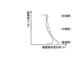
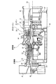
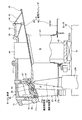
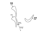
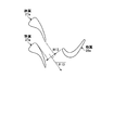
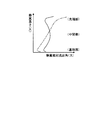
図1は、本発明の実施例1に係るガスタービンにおけるタービンの最終段動翼を表す概略図、図2は、実施例1のタービンの最終段動翼における先端部のスロート幅を表す概略図、図3は、実施例1のタービンの最終段動翼における中間部のスロート幅を表す概略図、図4は、実施例1のタービンの最終段動翼における基端部のスロート幅を表す概略図、図5は、最終段動翼の高さ方向における動翼相対流出角を表すグラフ、図6は、最終段動翼の高さ方向における最終段動翼の出口絶対全圧を表すグラフ、図7は、実施例1のガスタービンを表す概略図、図8は、実施例1のガスタービンにおける最終段静翼から排気ディフューザまでの構成を表す概略図である。 FIG. 1 is a schematic diagram illustrating a final stage moving blade of a turbine in a gas turbine according to a first embodiment of the present invention, and FIG. 2 is a schematic diagram illustrating a throat width of a tip portion of the final stage moving blade of the turbine of the first embodiment. FIG. 3 is a schematic diagram showing the throat width of the intermediate part in the final stage rotor blade of the turbine of the first embodiment, and FIG. 4 is a schematic diagram showing the throat width of the base end part in the final stage rotor blade of the turbine of the first embodiment. FIG. 5 is a graph showing a relative outflow angle of a moving blade in the height direction of the final stage moving blade, and FIG. 6 is a graph showing an absolute absolute pressure at the outlet of the final stage moving blade in the height direction of the final stage moving blade. FIG. 7 is a schematic diagram illustrating a gas turbine according to the first embodiment, and FIG. 8 is a schematic diagram illustrating a configuration from a final stage stationary blade to an exhaust diffuser in the gas turbine according to the first embodiment.
実施例1のガスタービンは、図7に示すように、圧縮機11と燃焼器12とタービン13により構成されている。このガスタービンには、図示しない発電機が連結されており、発電可能となっている。
As shown in FIG. 7, the gas turbine according to the first embodiment includes a
圧縮機11は、空気を取り込む空気取入口21を有し、圧縮機車室22内に複数の静翼体23と動翼体24が前後方向(後述するロータ32の軸方向)に交互に配設されてなり、その外側に抽気室25が設けられている。燃焼器12は、圧縮機11で圧縮された圧縮空気に対して燃料を供給し、点火することで燃焼可能となっている。タービン13は、タービン車室26内に複数の静翼体27と動翼体28が前後方向(後述するロータ32の軸方向)に交互に配設されている。このタービン車室26の下流側には、排気車室29を介して排気室30が配設されており、排気室30は、タービン13に連続する排気ディフューザ31を有している。
The
また、圧縮機11、燃焼器12、タービン13、排気室30の中心部を貫通するようにロータ(タービン軸)32が位置している。ロータ32は、圧縮機11側の端部が軸受部33により回転自在に支持される一方、排気室30側の端部が軸受部34により回転自在に支持されている。そして、このロータ32は、圧縮機11にて、各動翼体24が装着されたディスクが複数重ねられて固定され、タービン13にて、各動翼体28が装着されたディスクが複数重ねられて固定されており、圧縮機11側の端部に図示しない発電機の駆動軸が連結されている。
A rotor (turbine shaft) 32 is positioned so as to penetrate the
そして、このガスタービンは、圧縮機11の圧縮機車室22が脚部35に支持され、タービン13のタービン車室26が脚部36により支持され、排気室30が脚部37により支持されている。
In this gas turbine, the
従って、圧縮機11の空気取入口21から取り込まれた空気が、複数の静翼体23と動翼体24を通過して圧縮されることで高温・高圧の圧縮空気となる。燃焼器12にて、この圧縮空気に対して所定の燃料が供給され、燃焼する。そして、この燃焼器12で生成された作動流体である高温・高圧の燃焼ガスが、タービン13を構成する複数の静翼体27と動翼体28を通過することでロータ32を駆動回転し、このロータ32に連結された発電機を駆動する。一方、排気ガス(燃焼ガス)のエネルギは、排気室30の排気ディフューザ31により圧力に変換され減速されてから大気に放出される。
Therefore, the air taken in from the
上述したタービン13において、図8に示すように、円筒形状をなすタービン車室26は、その内側に複数の静翼体27と動翼体28が燃焼ガスの流動方向に沿って交互に配設されている。このタービン車室26は、排気ガスの流動方向の下流側に円筒形状をなす排気車室29が配設されている。この排気車室29は、排気ガスの流動方向の下流側に円筒形状をなす排気室30が配設されている。この排気室30は、排気ガスの流動方向の下流側に排気ダクト(図示略)が配設されている。この場合、タービン車室26、排気車室29、排気室30、排気ダクトは、それぞれ上下2分割に形成され、両者が一体に連結されて構成されている。
In the
そして、タービン車室26と排気車室29とは、複数の連結ボルト41により連結され、排気車室29と排気室30とは、熱伸びを吸収可能な複数の排気室サポート42,43により連結されている。この排気室サポート42,43は、短冊形状をなし、タービン13の軸方向に沿って延設されると共に、周方向に所定の間隔で複数並設されている。この排気室サポート42,43は、排気車室29と排気室30との間で温度差により熱伸びが発生したとき、変形することでその熱伸びを吸収可能となっている。この熱伸びは、タービン13の始動時などの過渡期や高負荷時に発生しやすい。また、排気車室29と排気室30との間には、各排気室サポート42,43の間に位置してガスシール44が設けられている。
The
排気車室29は、その内側に排気室30を構成する円筒形状をなす排気ディフューザ31が配置されている。この排気ディフューザ31は、円筒形状をなす外側ディフューザ45と内側ディフューザ46が複数のストラットシールド47により連結されて構成されている。このストラットシールド47は、円筒形状や楕円筒状などの中空構造をなし、排気ディフューザ31の周方向に均等間隔で複数設けられている。なお、上述した排気室サポート42,43及びガスシール44は、端部が排気室30を構成する排気ディフューザ31における外側ディフューザ45に連結されている。
The
ストラットシールド47内には、ストラット48が配設されている。このストラット48は、一端側が内側ディフューザ46を貫通して軸受部34を収容する軸受箱49に連結され、この軸受34によりロータ32が回転自在に支持されている。また、ストラット48は、他端側が外側ディフューザ45を貫通して排気車室29に固定されている。なお、ストラットシールド47内部の空間は、排気ディフューザ31(内側ディフューザ46)の内側の空間や、排気車室29と排気ディフューザ31(外側ディフューザ45)との間の空間に連通し、外部からこれらの空間に冷却空気を供給可能となっている。
A
また、タービン車室26は、その内側に複数の静翼体27と動翼体28が交互に配設されており、各段の翼環構造はほぼ同様の構成となっている。この場合、静翼体27は、複数の静翼27aが周方向に均等間隔で配置され、ロータ32側の基端部に内側シュラウド27bが固定され、タービン車室26側の先端部に外側シュラウド27cが固定されて構成されている。また、動翼体28は、同様に、動翼28aが周方向に均等間隔で配置され、基端部がロータ32に固定されるロータディスク28bに固定され、先端部がタービン車室26側に延出されて構成されている。そして、最終段静翼27aの下流側に最終段動翼28aが配置されている。
Further, the
ここで、タービン車室26における最終段翼環構造は、円筒形状をなすタービン車室本体51と、タービン車室本体51の内側に設けられて円筒形状をなす翼環52と、最終段動翼28aの外方に配置されて円筒形状をなす分割環53と、分割環53及び翼環52と最終段静翼27aの外側シュラウド27cとを連結する遮熱環54,55,56とから構成されている。
Here, the final stage blade ring structure in the
タービン13は、このように各段の翼環構造が構成されることから、タービン車室26を構成する内側シュラウド27c、分割環53などにより燃焼ガス通路Aが構成され、タービン車室26及び排気車室29の後部の内側に、排気ディフューザ31の前部が径方向に所定隙間をもって侵入し、シール装置57により連結されることで、排気ディフューザ31により構成される排気ガス通路Bが構成され、燃焼ガス通路Aと排気ガス通路Bが連続するようになっている。
Since the
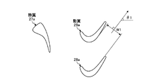
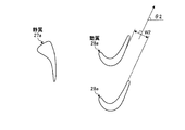
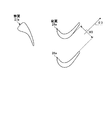
このように構成された実施例1のタービン13にて、図1に示すように、動翼(最終段動翼)28aは、長手方向における端部側のスロート幅が長手方向における中間部側のスロート幅より大きく設定されている。実施例1では、動翼28aは、長手方向における両端部側のスロート幅が長手方向における中間部側のスロート幅より大きく設定されている。この場合、動翼28aは、ロータ32に固定される基端部側のスロート幅及び先端部側のスロート幅が、基端部側と先端部側の間の中間部側のスロート幅より大きく設定され、且つ、先端部側のスロート幅が基端部側のスロート幅より大きく設定されている。
In the
具体的に説明すると、図2は、動翼28aにおける先端部側(タービン車室26及び分割環53側)の断面形状を表すものであり、隣接する動翼28a同士のスロート幅w1に設定することで、流出角(ゲージング角)θ1に設定されている。また、図3は、動翼28aにおける長手方向の中間部側の断面形状を表すものであり、隣接する動翼28a同士のスロート幅w2に設定することで、流出角(ゲージング角)θ2に設定されている。更に、図4は、動翼28aにおける基端部側(ロータ32及びロータディスク28b側)の断面形状を表すものであり、隣接する動翼28a同士のスロート幅w3に設定することで、流出角(ゲージング角)θ3に設定されている。
Specifically, FIG. 2 shows a cross-sectional shape of the moving
そして、動翼28aにおける先端部側及び基端部側のスロート幅w1,w3は、中間部側のスロート幅w2より大きくなっている。また、基端部側のスロート幅w3は、先端部側のスロート幅w1より大きくなっている。
The throat widths w1 and w3 on the distal end side and the proximal end side of the
なお、スロートとは、周方向に隣接する動翼28a間にて、燃焼ガスの流動方向の下流側における動翼28aの背面と腹面との間にある最小面積部であって、スロート幅wとは、このスロート部の幅である。また、流出方向とは、このスロート部の幅方向に直交する方向であり、流出角θとは、ロータ32の軸心方向に対する流出方向の角度である。
The throat is a minimum area portion between the back surface and the abdominal surface of the moving
従って、図5に示すように、従来の動翼は、一点鎖線で表すように、動翼の先端部側から基端部側に向けて流出角が徐々に小さくなるように設定されていた。これに対して、実施例1の動翼28aは、実線で表すように、流出角が動翼28aの先端部側から中間部に向けて徐々に大きくなった後に基端部側に向けて徐々に小さくなるように設定されている。
Therefore, as shown in FIG. 5, the conventional moving blade is set so that the outflow angle gradually decreases from the leading end side to the base end side of the moving blade, as represented by a one-dot chain line. On the other hand, in the moving
そのため、動翼28aは、先端部側と基端部側の流出角が小さい、つまり、スロート幅が大きいことから、燃焼ガスからの動力取得量が減少する一方、中間部側の流出角が大きい、つまり、スロート幅が小さいことから、燃焼ガスからの動力取得量が増加する。その結果、図6に示すように、従来は、一点鎖線で表すように、動翼の先端部側から基端部側までの動翼出口、つまり、排気ディフューザ入口での燃焼ガス(排気ガス)の全圧がほぼ一定となり、外側ディフューザや内側ディフューザの壁面近傍で排気ガスの剥離が生じやすくなり、排気ディフューザにおける圧力回復量が小さくなってしまう。これに対して、実施例1では、実線で表すように、動翼28aの中間部に比べて先端部側及び基端部側の動翼28aの出口、つまり、排気ディフューザ31の入口での燃焼ガス(排気ガス)の全圧が高くなることから、外側ディフューザ45及び内側ディフューザ46の壁面近傍で排気ガスの剥離が生じにくくなり、排気ディフューザ31における圧力回復量が大きくなる。
Therefore, the moving
このように実施例1のガスタービンにあっては、圧縮機11で圧縮した圧縮空気に燃焼器12で燃料を供給して燃焼し、発生した燃焼ガスをタービン13に供給することで回転動力を得るように構成し、円筒形状をなすタービン車室26の内側に静翼体27と動翼体28を燃焼ガスの流動方向に沿って交互に配置し、タービン車室26の後部に円筒形状をなす排気ディフューザ31を連結してタービン13を構成し、複数の動翼28aを周方向に等間隔で配置して動翼体28を構成し、この動翼28aの長手方向における端部側のスロート幅を、長手方向における中間部側のスロート幅より大きく設定している。
As described above, in the gas turbine according to the first embodiment, the
従って、動翼28aにおける端部側のスロート幅が中間部側のスロート幅より大きく設定されることで、端部側の流出角が中間部の流出角より小さくなり、端部側で燃焼ガスからの動力取得量が減少するが、中間部側で燃焼ガスからの動力取得量が増加する。その結果、動翼28aの中間部側の出口に比べて端部側の出口での燃焼ガスの全圧が高くなり、排気ディフューザ31の壁面近傍での排気ガスの剥離が生じにくくなることから、ここでの圧力回復量が増加し、効率的な排気ガスの圧力回復を行うことでタービン効率を向上して性能向上を可能とすることができる。
Therefore, by setting the throat width on the end portion side of the
また、実施例1のガスタービンでは、動翼28aの長手方向における両端部側のスロート幅を長手方向における中間部側のスロート幅より大きく設定している。従って、動翼28aにおける長手方向の両端部側から排気ディフューザ31に流れる排気ガスの流れを適正に制御することができ、ここでの圧力回復量を適正に増加することができる。
In the gas turbine of the first embodiment, the throat width on both end sides in the longitudinal direction of the
また、実施例1のガスタービンでは、最終段動翼体28における動翼28aの端部側のスロート幅を長手方向における中間部側のスロート幅より大きく設定している。従って、最終段動翼体28から排気ディフューザ31に流れる排気ガスの全圧を径方向で適正値とすることで、排気ディフューザ31における圧力回復量を増加させることができる。
In the gas turbine of the first embodiment, the throat width on the end portion side of the moving
なお、この実施例1では、動翼28aの長手方向における先端部側と基端部側の両方のスロート幅を中間部側のスロート幅より大きく設定したが、動翼28aの長手方向における先端部側のスロート幅だけ、または、基端部側のスロート幅だけを中間部側のスロート幅より大きく設定してもよい。
In the first embodiment, the throat width on both the distal end side and the proximal end side in the longitudinal direction of the moving
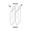
図9は、本発明の実施例2に係るガスタービンにおけるタービンの最終段静翼を表す概略図、図10は、実施例2のタービンの最終段静翼における先端部のスロート幅を表す概略図、図11は、実施例2のタービンの最終段静翼における中間部のスロート幅を表す概略図、図12は、実施例2のタービンの最終段静翼における基端部のスロート幅を表す概略図、図13は、最終段静翼の高さ方向における静翼相対流出角を表すグラフである。 FIG. 9 is a schematic diagram illustrating the final stage stationary blade of the turbine in the gas turbine according to the second embodiment of the present invention, FIG. 10 is a schematic diagram illustrating the throat width of the tip of the final stage stationary blade of the turbine of the second embodiment, and FIG. FIG. 12 is a schematic diagram showing the throat width of the intermediate part in the final stage stationary blade of the turbine of Example 2, FIG. 12 is a schematic diagram showing the throat width of the base end part in the final stage stationary blade of the turbine of Example 2, and FIG. It is a graph showing the stationary blade relative outflow angle in the height direction.
実施例2のガスタービンのタービンにて、図9に示すように、静翼(最終段静翼)27aは、長手方向における端部側のスロート幅が長手方向における中間部側のスロート幅より大きく設定されている。実施例2では、静翼27aは、長手方向における両端部側のスロート幅が長手方向における中間部側のスロート幅より大きく設定されている。この場合、静翼27aは、内側シュラウド27bに固定される基端部側のスロート幅及び外側シュラウド27cに固定される先端部側のスロート幅が、基端部側と先端部側の間の中間部側のスロート幅より大きく設定され、且つ、先端部側のスロート幅と基端部側のスロート幅とがほぼ同じに設定されている。
In the turbine of the gas turbine of the second embodiment, as shown in FIG. 9, the stationary blade (final stage stationary blade) 27a is set such that the throat width on the end side in the longitudinal direction is larger than the throat width on the intermediate portion side in the longitudinal direction. ing. In Example 2, the
具体的に説明すると、図10は、静翼27aにおける先端部側(外側シュラウド27c側)の断面形状を表すものであり、隣接する静翼27a同士のスロート幅w11に設定することで、流出角(ゲージング角)θ11に設定されている。また、図11は、静翼27aにおける長手方向の中間部側の断面形状を表すものであり、隣接する静翼27a同士のスロート幅w12に設定することで、流出角(ゲージング角)θ12に設定されている。更に、図12は、静翼27aにおける基端部側(内側シュラウド27b側)の断面形状を表すものであり、隣接する静翼27a同士のスロート幅w13に設定することで、流出角(ゲージング角)θ13に設定されている。
More specifically, FIG. 10 shows the cross-sectional shape of the tip side (outside
そして、静翼27aにおける先端部側及び基端部側のスロート幅w11,w13は、中間部側のスロート幅w12より大きくなっている。また、先端部側のスロート幅w11と基端部側のスロート幅w13とは、ほぼ同じ大きさとなっている。
The throat widths w11 and w13 on the distal end side and the proximal end side of the
なお、スロートとは、周方向に隣接する静翼27a間にて、燃焼ガスの流動方向の下流側における静翼27aの背面と腹面との間にある最小面積部であって、スロート幅wとは、このスロート部の幅である。また、流出方向とは、このスロート部の幅方向に直交する方向であり、流出角θとは、ロータ32の軸心方向に対する流出方向の角度である。
The throat is the smallest area portion between the back surface and the abdominal surface of the
従って、図13に示すように、従来の静翼は、一点鎖線で表すように、静翼の先端部側から基端部側に向けて流出角が徐々に小さくなるように設定されていた。これに対して、実施例2の静翼27aは、実線で表すように、流出角が静翼27aの先端部側から中間部に向けて徐々に大きくなった後に基端部側に向けて徐々に小さくなるように設定されている。
Therefore, as shown in FIG. 13, the conventional stationary blade is set so that the outflow angle gradually decreases from the distal end side to the proximal end side of the stationary blade, as represented by a one-dot chain line. On the other hand, in the
そのため、静翼27aは、先端部側と基端部側の流出角が小さくなり、下流側に位置する動翼28aの先端部側と基端部側は流入角が小さくなる。その結果、動翼28aの先端部側と基端部側は転向角が減少し、燃焼ガスからの動力取得量が減少する。一方、静翼27aの中間部は流出角が大きくなり、下流側に位置する動翼28aの中間部の流入角が大きくなる。その結果、動翼28aの中間部の転向角は増加し、燃焼ガスからの動力取得量は増加する。その結果、従来は、実施例1で説明した図6に一点鎖線で表すように、動翼の先端部側から基端部側までの動翼出口、つまり、排気ディフューザ入口での燃焼ガス(排気ガス)の全圧がほぼ一定となり、外側ディフューザや内側ディフューザの壁面近傍で排気ガスの剥離が生じやすくなり、排気ディフューザにおける圧力回復量が小さくなってしまう。これに対して、実施例2では、図6に実線で表すように、動翼28aの中間部に比べて先端部側及び基端部側の動翼28aの出口、つまり、排気ディフューザ31の入口での燃焼ガス(排気ガス)の全圧が高くなることから、外側ディフューザ45及び内側ディフューザ46の壁面近傍で排気ガスの剥離が生じにくくなり、排気ディフューザ31における圧力回復量が大きくなる。
Therefore, the
このように実施例2のガスタービンにあっては、複数の静翼27aを周方向に等間隔で固定して静翼2体7を構成し、静翼27aのロータ32側に配置される基端部側のスロート幅及び先端部側のスロート幅を、基端部側と先端部側の間の中間部側のスロート幅より大きく設定し、基端部側のスロート幅と先端部側のスロート幅とをほぼ同じに設定している。
As described above, in the gas turbine according to the second embodiment, the plurality of
従って、静翼27aにおける端部側のスロート幅が中間部側のスロート幅より大きく設定されることで、端部側の流出角が中間部の流出角より小さくなり、端部側で下流側に位置する動翼28aの流入角および転向角が減少し、燃焼ガスからの動力取得量が減少するが、中間部側で燃焼ガスからの動力取得量が増加する。その結果、動翼28aの中間部側の出口に比べて端部側の出口での燃焼ガスの全圧が高くなり、排気ディフューザ31の壁面近傍での排気ガスの剥離が生じにくくなることから、ここでの圧力回復量が増加し、効率的な排気ガスの圧力回復を行うことでタービン効率を向上して性能向上を可能とすることができる。
Therefore, by setting the throat width on the end side of the
実施例2のガスタービンでは、最終段静翼体27にて、静翼27aの長手方向における端部側のスロート幅を長手方向における中間部側のスロート幅より大きく設定している。従って、最終段静翼体27aから最終段動翼体28aを通過して排気ディフューザ31に流れる排気ガスの全圧を径方向で適正値とすることができ、排気ディフューザ31における圧力回復量を増加させることができる。
In the gas turbine of the second embodiment, in the final stage
なお、この実施例2では、静翼27aの長手方向における先端部側と基端部側の両方のスロート幅を中間部側のスロート幅より大きく設定したが、静翼27aの長手方向における先端部側のスロート幅だけ、または、基端部側のスロート幅だけを中間部側のスロート幅より大きく設定してもよい。
In the second embodiment, the throat width on both the distal end side and the proximal end portion side in the longitudinal direction of the
また、実施例1における動翼体28の動翼28aの形状と、実施例2における静翼体27の静翼27aの形状との両方を適用したタービンを適用することで、更なるタービン効率を向上して性能向上を可能とすることができる。
Further, by applying a turbine to which both the shape of the moving
11 圧縮機
12 燃焼器
13 タービン
26 タービン車室
27 静翼体
27a 最終段静翼
27b 内側シュラウド
27c 外側シュラウド
28 動翼体
28a 最終段動翼
28b ロータディスク
29 排気車室
30 排気室
31 排気ディフューザ
32 ロータ(タービン軸)
45 外側ディフューザ
46 内側ディフューザ
48 ストラット
51 タービン車室本体
52 翼環
53 分割環
54,55,56 遮熱環
A 燃焼ガス通路
B 排気ガス通路
DESCRIPTION OF
45 Outer diffuser 46
Claims (6)
前記タービンは、円筒形状をなすタービン車室の内側に静翼体と動翼体が燃焼ガスの流動方向に沿って交互に配置され、前記タービン車室の後部に円筒形状をなす排気ディフューザが連結されて構成され、
前記静翼体は、複数の静翼が周方向に等間隔で配置されて構成されると共に、前記動翼体は、複数の動翼が周方向に等間隔で固定されて構成され、
前記静翼または前記動翼は、長手方向における端部側のスロート幅が長手方向における中間部側のスロート幅より大きく設定される、
ことを特徴とするガスタービン。 In a gas turbine that obtains rotational power by supplying fuel to compressed air compressed by a compressor and burning it with a combustor and supplying the generated combustion gas to the turbine,
In the turbine, a stationary blade body and a moving blade body are alternately arranged along a flow direction of combustion gas inside a cylindrical turbine casing, and a cylindrical exhaust diffuser is connected to a rear portion of the turbine casing. Be configured,
The stationary blade body is configured by arranging a plurality of stationary blades at equal intervals in the circumferential direction, and the moving blade body is configured by fixing a plurality of moving blades at equal intervals in the circumferential direction,
The stationary blade or the moving blade is set such that the throat width on the end portion side in the longitudinal direction is larger than the throat width on the intermediate portion side in the longitudinal direction.
A gas turbine characterized by that.
Priority Applications (8)
| Application Number | Priority Date | Filing Date | Title |
|---|---|---|---|
| JP2011076017A JP5868605B2 (en) | 2011-03-30 | 2011-03-30 | gas turbine |
| EP12763068.9A EP2692987B1 (en) | 2011-03-30 | 2012-03-23 | Gas turbine |
| PCT/JP2012/057592 WO2012133224A1 (en) | 2011-03-30 | 2012-03-23 | Gas turbine |
| KR1020137025559A KR20130129301A (en) | 2011-03-30 | 2012-03-23 | Gas turbine |
| US14/008,513 US9719354B2 (en) | 2011-03-30 | 2012-03-23 | Gas turbine with improved blade and vane and flue gas diffuser |
| CN201280016252.2A CN103459775B (en) | 2011-03-30 | 2012-03-23 | Gas turbine |
| KR1020157032763A KR101760199B1 (en) | 2011-03-30 | 2012-03-23 | Gas turbine |
| KR1020177019434A KR101839279B1 (en) | 2011-03-30 | 2012-03-23 | Gas turbine |
Applications Claiming Priority (1)
| Application Number | Priority Date | Filing Date | Title |
|---|---|---|---|
| JP2011076017A JP5868605B2 (en) | 2011-03-30 | 2011-03-30 | gas turbine |
Publications (3)
| Publication Number | Publication Date |
|---|---|
| JP2012207648A true JP2012207648A (en) | 2012-10-25 |
| JP2012207648A5 JP2012207648A5 (en) | 2015-01-29 |
| JP5868605B2 JP5868605B2 (en) | 2016-02-24 |
Family
ID=46930946
Family Applications (1)
| Application Number | Title | Priority Date | Filing Date |
|---|---|---|---|
| JP2011076017A Active JP5868605B2 (en) | 2011-03-30 | 2011-03-30 | gas turbine |
Country Status (6)
| Country | Link |
|---|---|
| US (1) | US9719354B2 (en) |
| EP (1) | EP2692987B1 (en) |
| JP (1) | JP5868605B2 (en) |
| KR (3) | KR101839279B1 (en) |
| CN (1) | CN103459775B (en) |
| WO (1) | WO2012133224A1 (en) |
Cited By (4)
| Publication number | Priority date | Publication date | Assignee | Title |
|---|---|---|---|---|
| US10655471B2 (en) | 2015-02-10 | 2020-05-19 | Mitsubishi Hitachi Power Systems, Ltd. | Turbine and gas turbine |
| US10794397B2 (en) | 2015-04-03 | 2020-10-06 | Mitsubishi Heavy Industries, Ltd. | Rotor blade and axial flow rotary machine |
| JPWO2022201932A1 (en) * | 2021-03-24 | 2022-09-29 | ||
| CN115210451A (en) * | 2020-03-04 | 2022-10-18 | 诺沃皮尼奥内技术股份有限公司 | Improved turbine and blade for protecting roots from hot gas of flow path |
Families Citing this family (2)
| Publication number | Priority date | Publication date | Assignee | Title |
|---|---|---|---|---|
| JP6396093B2 (en) * | 2014-06-26 | 2018-09-26 | 三菱重工業株式会社 | Turbine rotor cascade, turbine stage and axial turbine |
| RU191926U1 (en) * | 2019-02-28 | 2019-08-28 | Публичное Акционерное Общество "Одк-Сатурн" | TURBINE NOZZLE DEVICE |
Citations (6)
| Publication number | Priority date | Publication date | Assignee | Title |
|---|---|---|---|---|
| JP2000045704A (en) * | 1998-07-31 | 2000-02-15 | Toshiba Corp | Steam turbine |
| JP2003020904A (en) * | 2001-07-11 | 2003-01-24 | Toshiba Corp | Axial turbine blade and axial turbine stage |
| JP2004263602A (en) * | 2003-02-28 | 2004-09-24 | Toshiba Corp | Nozzle blades, rotor blades and turbine stage of axial flow turbine |
| JP2010180827A (en) * | 2009-02-06 | 2010-08-19 | Mitsubishi Heavy Ind Ltd | Gas turbine blade and gas turbine |
| JP2011021525A (en) * | 2009-07-15 | 2011-02-03 | Toshiba Corp | Turbine blade cascade, and turbine stage and axial flow turbine using the same |
| JP2011038491A (en) * | 2009-08-18 | 2011-02-24 | Mitsubishi Heavy Ind Ltd | Turbine exhaust structure and gas turbine |
Family Cites Families (15)
| Publication number | Priority date | Publication date | Assignee | Title |
|---|---|---|---|---|
| JP3786443B2 (en) * | 1995-02-14 | 2006-06-14 | 株式会社東芝 | Turbine nozzle, turbine blade and turbine stage |
| JP3773565B2 (en) | 1995-10-16 | 2006-05-10 | 株式会社東芝 | Turbine nozzle |
| US6004095A (en) * | 1996-06-10 | 1999-12-21 | Massachusetts Institute Of Technology | Reduction of turbomachinery noise |
| JP3621216B2 (en) | 1996-12-05 | 2005-02-16 | 株式会社東芝 | Turbine nozzle |
| JP2002213202A (en) * | 2001-01-12 | 2002-07-31 | Mitsubishi Heavy Ind Ltd | Gas turbine blade |
| JP4373629B2 (en) | 2001-08-31 | 2009-11-25 | 株式会社東芝 | Axial flow turbine |
| ITMI20040710A1 (en) * | 2004-04-09 | 2004-07-09 | Nuovo Pignone Spa | HIGH EFFICIENCY STATOR FOR SECOND STAGE OF A GAS TURBINE |
| US7547187B2 (en) * | 2005-03-31 | 2009-06-16 | Hitachi, Ltd. | Axial turbine |
| JP5047000B2 (en) | 2008-02-27 | 2012-10-10 | 三菱重工業株式会社 | Exhaust chamber connection structure and gas turbine |
| CN103557035B (en) | 2008-02-27 | 2015-04-29 | 三菱日立电力系统株式会社 | Connection structure of exhaust chamber, support structure of turbine, and gas turbine |
| JP2013015018A (en) * | 2009-09-29 | 2013-01-24 | Hitachi Ltd | Turbine stator vane designing method, turbine stator vane, and steam turbine device using turbine stator vane |
| ITMI20101447A1 (en) | 2010-07-30 | 2012-01-30 | Alstom Technology Ltd | "LOW PRESSURE STEAM TURBINE AND METHOD FOR THE FUNCTIONING OF THE SAME" |
| EP2434094A3 (en) | 2010-09-28 | 2018-02-21 | Mitsubishi Hitachi Power Systems, Ltd. | Steam turbine stator vane and steam turbine |
| US8708639B2 (en) * | 2010-10-11 | 2014-04-29 | The Coca-Cola Company | Turbine bucket shroud tail |
| US20130064638A1 (en) * | 2011-09-08 | 2013-03-14 | Moorthi Subramaniyan | Boundary Layer Blowing Using Steam Seal Leakage Flow |
-
2011
- 2011-03-30 JP JP2011076017A patent/JP5868605B2/en active Active
-
2012
- 2012-03-23 KR KR1020177019434A patent/KR101839279B1/en active Active
- 2012-03-23 KR KR1020137025559A patent/KR20130129301A/en not_active Ceased
- 2012-03-23 CN CN201280016252.2A patent/CN103459775B/en active Active
- 2012-03-23 EP EP12763068.9A patent/EP2692987B1/en active Active
- 2012-03-23 WO PCT/JP2012/057592 patent/WO2012133224A1/en not_active Ceased
- 2012-03-23 US US14/008,513 patent/US9719354B2/en active Active
- 2012-03-23 KR KR1020157032763A patent/KR101760199B1/en active Active
Patent Citations (6)
| Publication number | Priority date | Publication date | Assignee | Title |
|---|---|---|---|---|
| JP2000045704A (en) * | 1998-07-31 | 2000-02-15 | Toshiba Corp | Steam turbine |
| JP2003020904A (en) * | 2001-07-11 | 2003-01-24 | Toshiba Corp | Axial turbine blade and axial turbine stage |
| JP2004263602A (en) * | 2003-02-28 | 2004-09-24 | Toshiba Corp | Nozzle blades, rotor blades and turbine stage of axial flow turbine |
| JP2010180827A (en) * | 2009-02-06 | 2010-08-19 | Mitsubishi Heavy Ind Ltd | Gas turbine blade and gas turbine |
| JP2011021525A (en) * | 2009-07-15 | 2011-02-03 | Toshiba Corp | Turbine blade cascade, and turbine stage and axial flow turbine using the same |
| JP2011038491A (en) * | 2009-08-18 | 2011-02-24 | Mitsubishi Heavy Ind Ltd | Turbine exhaust structure and gas turbine |
Cited By (8)
| Publication number | Priority date | Publication date | Assignee | Title |
|---|---|---|---|---|
| US10655471B2 (en) | 2015-02-10 | 2020-05-19 | Mitsubishi Hitachi Power Systems, Ltd. | Turbine and gas turbine |
| US10794397B2 (en) | 2015-04-03 | 2020-10-06 | Mitsubishi Heavy Industries, Ltd. | Rotor blade and axial flow rotary machine |
| CN115210451A (en) * | 2020-03-04 | 2022-10-18 | 诺沃皮尼奥内技术股份有限公司 | Improved turbine and blade for protecting roots from hot gas of flow path |
| CN115244277A (en) * | 2020-03-04 | 2022-10-25 | 诺沃皮尼奥内技术股份有限公司 | Improved Turbine and Blades for Root Protection from Flow Path Hot Gas |
| JPWO2022201932A1 (en) * | 2021-03-24 | 2022-09-29 | ||
| WO2022201932A1 (en) * | 2021-03-24 | 2022-09-29 | 三菱パワー株式会社 | Turbine and gas turbine |
| US12305573B2 (en) | 2021-03-24 | 2025-05-20 | Mitsubishi Heavy Industries, Ltd. | Gas turbine engine exhaust diffuser having multiple inclined surfaces at different angles |
| JP7692988B2 (en) | 2021-03-24 | 2025-06-16 | 三菱重工業株式会社 | Gas turbine |
Also Published As
| Publication number | Publication date |
|---|---|
| KR20150133862A (en) | 2015-11-30 |
| US20140041395A1 (en) | 2014-02-13 |
| KR101760199B1 (en) | 2017-07-31 |
| EP2692987B1 (en) | 2021-01-20 |
| CN103459775A (en) | 2013-12-18 |
| US9719354B2 (en) | 2017-08-01 |
| CN103459775B (en) | 2015-09-16 |
| KR101839279B1 (en) | 2018-03-15 |
| KR20170085610A (en) | 2017-07-24 |
| JP5868605B2 (en) | 2016-02-24 |
| KR20130129301A (en) | 2013-11-27 |
| EP2692987A4 (en) | 2014-08-27 |
| WO2012133224A1 (en) | 2012-10-04 |
| EP2692987A1 (en) | 2014-02-05 |
Similar Documents
| Publication | Publication Date | Title |
|---|---|---|
| JP5951187B2 (en) | Turbine exhaust structure and gas turbine | |
| JP6208922B2 (en) | Blade used with a rotating machine and method for assembling such a rotating machine | |
| JP6468414B2 (en) | Compressor vane, axial compressor, and gas turbine | |
| US11035237B2 (en) | Blade with tip rail cooling | |
| US10753207B2 (en) | Airfoil with tip rail cooling | |
| JP5868605B2 (en) | gas turbine | |
| CN103184900B (en) | For turbine shroud to the cellular seal of front step | |
| US9175565B2 (en) | Systems and apparatus relating to seals for turbine engines | |
| JP2017078416A (en) | Turbine blade | |
| JP2015121220A (en) | Snubber configurations for turbine rotor blades | |
| CN108868898A (en) | Apparatus and method for cooling an airfoil tip of a turbine engine | |
| EP2551458A2 (en) | Blade Cooling and Sealing System | |
| CN107084001B (en) | Airfoils for Gas Turbine Engines | |
| JP2019056366A (en) | Shield for turbine engine airfoil | |
| CN107061015A (en) | Gas-turbine unit with cooling fluid path | |
| CN108691658A (en) | Turbine engine with platform cooling circuit |
Legal Events
| Date | Code | Title | Description |
|---|---|---|---|
| A521 | Request for written amendment filed |
Free format text: JAPANESE INTERMEDIATE CODE: A523 Effective date: 20140226 |
|
| A621 | Written request for application examination |
Free format text: JAPANESE INTERMEDIATE CODE: A621 Effective date: 20140226 |
|
| A521 | Request for written amendment filed |
Free format text: JAPANESE INTERMEDIATE CODE: A523 Effective date: 20141208 |
|
| A131 | Notification of reasons for refusal |
Free format text: JAPANESE INTERMEDIATE CODE: A131 Effective date: 20150331 |
|
| A521 | Request for written amendment filed |
Free format text: JAPANESE INTERMEDIATE CODE: A523 Effective date: 20150529 |
|
| TRDD | Decision of grant or rejection written | ||
| A01 | Written decision to grant a patent or to grant a registration (utility model) |
Free format text: JAPANESE INTERMEDIATE CODE: A01 Effective date: 20151208 |
|
| A61 | First payment of annual fees (during grant procedure) |
Free format text: JAPANESE INTERMEDIATE CODE: A61 Effective date: 20160106 |
|
| R151 | Written notification of patent or utility model registration |
Ref document number: 5868605 Country of ref document: JP Free format text: JAPANESE INTERMEDIATE CODE: R151 |
|
| S531 | Written request for registration of change of domicile |
Free format text: JAPANESE INTERMEDIATE CODE: R313531 |
|
| S111 | Request for change of ownership or part of ownership |
Free format text: JAPANESE INTERMEDIATE CODE: R313113 |
|
| R350 | Written notification of registration of transfer |
Free format text: JAPANESE INTERMEDIATE CODE: R350 |
|
| R350 | Written notification of registration of transfer |
Free format text: JAPANESE INTERMEDIATE CODE: R350 |
|
| S533 | Written request for registration of change of name |
Free format text: JAPANESE INTERMEDIATE CODE: R313533 |
|
| R350 | Written notification of registration of transfer |
Free format text: JAPANESE INTERMEDIATE CODE: R350 |