JP2012207491A - Travel control device of construction machine - Google Patents
Travel control device of construction machine Download PDFInfo
- Publication number
- JP2012207491A JP2012207491A JP2011075366A JP2011075366A JP2012207491A JP 2012207491 A JP2012207491 A JP 2012207491A JP 2011075366 A JP2011075366 A JP 2011075366A JP 2011075366 A JP2011075366 A JP 2011075366A JP 2012207491 A JP2012207491 A JP 2012207491A
- Authority
- JP
- Japan
- Prior art keywords
- traveling
- pilot
- control valve
- remote control
- control device
- Prior art date
- Legal status (The legal status is an assumption and is not a legal conclusion. Google has not performed a legal analysis and makes no representation as to the accuracy of the status listed.)
- Granted
Links
- 238000010276 construction Methods 0.000 title claims description 12
- 230000004044 response Effects 0.000 claims abstract description 7
- 238000006073 displacement reaction Methods 0.000 claims description 3
- 230000001934 delay Effects 0.000 abstract 1
- 238000000034 method Methods 0.000 description 12
- 230000008569 process Effects 0.000 description 9
- 230000003111 delayed effect Effects 0.000 description 5
- 230000000630 rising effect Effects 0.000 description 5
- 238000010586 diagram Methods 0.000 description 4
- 230000000694 effects Effects 0.000 description 3
- 230000009471 action Effects 0.000 description 2
- 238000001514 detection method Methods 0.000 description 2
- 230000001133 acceleration Effects 0.000 description 1
- 230000008901 benefit Effects 0.000 description 1
- 230000008859 change Effects 0.000 description 1
- 238000005553 drilling Methods 0.000 description 1
- 238000005516 engineering process Methods 0.000 description 1
Images


Landscapes
- Operation Control Of Excavators (AREA)
Abstract
Description
本発明は油圧ショベル等のクローラ走行体を備えた建設機械の走行制御装置に関するものである。 The present invention relates to a traveling control device for a construction machine including a crawler traveling body such as a hydraulic excavator.
油圧ショベルを例にとって背景技術を説明する。 The background art will be described using a hydraulic excavator as an example.
油圧ショベルは、クローラ式の下部走行体上に上部旋回体が地面に対して鉛直となる軸のまわりに旋回自在に搭載され、この上部旋回体にブーム、アーム、バケットを備えた掘削アタッチメントが取付けられて構成される。 The hydraulic excavator is mounted on a crawler type lower traveling body so that the upper swinging body can swing around an axis perpendicular to the ground, and a drilling attachment equipped with a boom, an arm, and a bucket is attached to the upper swinging body. Configured.
下部走行体は左右のクローラ走行装置を備え、この両クローラ走行装置が、油圧ポンプを駆動源とする別々の走行モータ(油圧モータ)によって駆動される。 The lower traveling body includes left and right crawler traveling devices, and both the crawler traveling devices are driven by separate traveling motors (hydraulic motors) using a hydraulic pump as a drive source.
この両走行モータは、上部旋回体に設けられた個別の操作手段(通常はレバー操作されるリモコン弁。以下、この例で説明する)の操作に基づくコントロールバルブの切換わり作動によって回転方向と速度が制御される。 These two traveling motors are rotated in the direction and speed by switching the control valve based on the operation of individual operating means (normally a remote-controlled valve operated by a lever, which will be described in this example) provided on the upper swing body. Is controlled.
この油圧ショベルにおいては、上部旋回体の旋回によってリモコン弁の操作方向と下部走行体の進行方向が逆になる事態が生じる。 In this hydraulic excavator, there occurs a situation in which the operation direction of the remote control valve and the traveling direction of the lower traveling body are reversed due to the turning of the upper rotating body.
すなわち、オペレータが前進操作したつもりが後進してしまう事態、または逆の事態である。 That is, a situation in which the operator intends to move forward moves backward or vice versa.
この場合、通常走行時と同じ速度の立ち上がり(加速度)で発進させると、オペレータが誤操作に気づいて修正する余裕がないため好ましくない。 In this case, it is not preferable to start the vehicle at the same rising speed (acceleration) as that during normal traveling because the operator has no room for recognizing an erroneous operation and correcting it.
この点の対策として出願人は、走行発進時に、リモコン弁の操作に対してポンプ吐出量、またはコントロールバルブの切換えに応答遅れを持たせることにより、走行モータの速度の立ち上がりを緩やかにしてゆっくりと発進させる緩発進方式を提案した(特許文献1参照) As countermeasures against this point, the applicant, at the time of traveling start, slowly slows the rising of the traveling motor speed by giving a delay in response to the pump discharge amount or control valve switching with respect to the operation of the remote control valve. Proposed a slow start system to start (see Patent Document 1)
上記公知技術では、両走行モータが同時に同方向に駆動される両走行時(直進時)と、一方の走行モータのみが駆動される片走行時(ピボットターン時)とに関係なく、走行操作があれば同じ特性で緩発進させる構成をとっている。 In the above-mentioned known technology, the traveling operation is performed regardless of both the traveling time in which both traveling motors are simultaneously driven in the same direction (straight traveling) and the single traveling time in which only one traveling motor is driven (in the pivot turn). If there is, it is configured to start slowly with the same characteristics.
ところが、片走行時には、直進時と比べて走行負荷が格段に大きくて必要な走行トルクも大きくなるため、狙いとする応答遅れからさらに遅れた後で動き出す。 However, during one-way travel, the travel load is much larger than when traveling straight, and the required travel torque also increases. Therefore, the vehicle begins to move after further delay from the targeted response delay.
つまり、緩発進のための遅れ時間を超える発進遅れの後、急発進することになり、緩発進制御が生かせず、誤操作を防止する(誤操作をオペレータに気づかせて修正操作させる)という本来の目的が達成できない。 In other words, after the start delay that exceeds the delay time for slow start, it will start suddenly, the slow start control can not be utilized, and the original purpose of preventing erroneous operation (notifying the operator of correct operation) Cannot be achieved.
そこで本発明は、片走行時にも両走行時と同じ緩発進機能を確保することができる建設機械の走行制御装置を提供するものである。 Therefore, the present invention provides a traveling control device for a construction machine that can ensure the same slow start function as that during both travelings even during one traveling.
上記課題を解決する手段として、本発明においては、左右の走行モータを駆動源とする左右両側の走行装置によって前進、後進する走行体と、上記両走行モータの作動を個別に指令する左右の走行操作手段と、上記左右の走行操作手段の操作を検出する操作検出手段と、この操作検出手段からの信号に基づいて走行時に上記走行操作手段の操作に対する走行モータの応答を遅らせて走行体を緩発進させる遅延処理を行う制御手段とを備えた建設機械の走行制御装置において、上記制御手段は、上記左右の走行モータが同時に同方向に駆動される両走行時と、一方の走行モータのみが駆動される片走行時とで発進の速度の立ち上がりが同じとなるように、両走行時と片走行時とに応じて上記遅延処理の特性を異ならせるように構成したものである。 As means for solving the above-described problems, in the present invention, the left and right traveling motors using the left and right traveling motors as drive sources are used to travel forward and backward, and left and right traveling that individually command the operation of both the traveling motors. Based on the operation means, the operation detection means for detecting the operation of the left and right travel operation means, and the signal from the operation detection means, the response of the travel motor to the operation of the travel operation means is delayed during travel to loosen the traveling body. In the traveling control apparatus for a construction machine, comprising a control means for performing a delaying process for starting, the control means is driven during both travels in which the left and right travel motors are simultaneously driven in the same direction, and only one travel motor is driven. The characteristic of the delay processing is made different according to both the traveling and the one-way traveling so that the starting speed rises at the same time during the one-way traveling. .
このように、片走行時には両走行時よりも走行負荷が大きくて速度の立ち上がりが遅くなる点に着目し、この片走行時の発進速度の立ち上がり(速度勾配)が両走行時と同じとなるように遅延処理特性を異ならせる構成としたから、片走行時にも両走行時と同じ緩発進機能を確保し、誤操作を防止することができる。 In this way, paying attention to the fact that the traveling load is larger and the rise of speed is slower than that of both runs during one run, so that the start speed rise (speed gradient) during this one run is the same as during both runs. Since the delay processing characteristics are made different from each other, the same slow start function can be ensured even during one traveling as in both traveling, and erroneous operation can be prevented.
本発明においては、上記左右の走行モータとして油圧ポンプを油圧源とする油圧モータ、上記操作手段としてパイロットポンプを圧源とするリモコン弁をそれぞれ用い、このリモコン弁から送られるパイロット圧により油圧パイロット式のコントロールバルブを操作して上記走行モータの回転方向と速度を制御するように構成し、上記制御手段は、両走行時と片走行時とに応じて、上記リモコン弁の操作に対する上記パイロット圧の遅延処理の特性を異ならせるように構成するのが望ましい(請求項2〜4)。 In the present invention, a hydraulic motor using a hydraulic pump as a hydraulic source is used as the left and right traveling motors, and a remote control valve using a pilot pump as a pressure source is used as the operating means. The control means controls the rotational direction and speed of the travel motor, and the control means controls the pilot pressure with respect to the operation of the remote control valve according to both travel and single travel. It is desirable that the delay processing has different characteristics (claims 2 to 4).
このように、コントロールバルブのパイロット圧制御によって両走行時と片走行時の遅延処理特性を異ならせるパイロット圧制御方式をとれば、低圧制御であるため制御が容易で、しかも制御の応答性が良いものとなる。 In this way, if the pilot pressure control system that makes the delay processing characteristics different during both traveling and single traveling by pilot pressure control of the control valve is adopted, control is easy because of low pressure control, and control response is good. It will be a thing.
この場合、上記パイロットポンプとリモコン弁とを結ぶパイロットポンプ回路に、リモコン弁に送られるパイロット一次圧を制御する電磁比例減圧弁を設け、上記制御手段は、両走行時と片走行時とに応じて、上記リモコン弁の操作に対する上記パイロット一次圧の遅延処理特性を異ならせるように構成してもよいし(請求項3)、上記リモコン弁とコントロールバルブとを結ぶパイロット回路に、上記コントロールバルブに送られるパイロット圧を制御する電磁比例減圧弁を設け、上記制御手段は、両走行時と片走行時とに応じて、上記リモコン弁の操作に対するパイロット圧の遅延処理特性を異ならせるように構成してもよい(請求項4)。 In this case, an electromagnetic proportional pressure reducing valve for controlling the pilot primary pressure sent to the remote control valve is provided in the pilot pump circuit connecting the pilot pump and the remote control valve, and the control means is adapted for both travel and single travel. The pilot primary pressure delay processing characteristic for the operation of the remote control valve may be made different (Claim 3), or a pilot circuit connecting the remote control valve and the control valve may be connected to the control valve. An electromagnetic proportional pressure reducing valve for controlling the pilot pressure to be sent is provided, and the control means is configured to vary the delay processing characteristics of the pilot pressure with respect to the operation of the remote control valve according to both traveling and one traveling. (Claim 4).
前者のパイロット一次圧を制御する構成によれば、一つの電磁比例減圧弁で左右のコントロールバルブを制御できるため、コストが安くてすむ。 According to the former configuration that controls the pilot primary pressure, the left and right control valves can be controlled by one electromagnetic proportional pressure reducing valve, so that the cost can be reduced.
あるいは、他の制御方式として、上記油圧ポンプとして、レギュレータによって吐出量が制御される可変容量ポンプを用い、上記制御手段は、両走行時と片走行時とに応じて、上記リモコン弁の操作に対するポンプ吐出量の遅延処理特性を異ならせるように構成してもよいし(請求項5)、上記油圧ポンプをエンジンによって駆動するように構成し、上記制御手段は、両走行時と片走行時とに応じて、上記リモコン弁の操作に対するエンジン回転数の遅延処理特性を異ならせるように構成してもよい(請求項6)。 Alternatively, as another control method, a variable displacement pump whose discharge amount is controlled by a regulator is used as the hydraulic pump, and the control means responds to the operation of the remote control valve according to both traveling and single traveling. The delay characteristic of the pump discharge amount may be made different (Claim 5), or the hydraulic pump may be driven by an engine, and the control means may be used for both traveling and single traveling. Accordingly, the delay processing characteristic of the engine speed with respect to the operation of the remote control valve may be made different (claim 6).
この構成によれば、レギュレータまたはエンジンのガバナという既存設備を制御すればよく、緩発進のために追加すべき制御設備が不要となるため、コストが安くてすむ。 According to this configuration, it is only necessary to control the existing equipment such as the regulator or the governor of the engine, and the control equipment to be added for the slow start is unnecessary, so that the cost can be reduced.
本発明によると、片走行時にも両走行時と同じ緩発進機能を確保して誤操作を防止し、安全性を高めることができる。 According to the present invention, the same slow start function as that during both travelings can be ensured even during one traveling to prevent erroneous operation and to improve safety.
実施形態は油圧ショベルを適用対象としている。 The embodiment is applied to a hydraulic excavator.
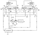
図1はこの油圧ショベルの走行回路を示し、走行駆動系を実線で、パイロット系を破線で、制御系を斜線付きの実線でそれぞれ示す。 FIG. 1 shows a traveling circuit of this hydraulic excavator, in which a traveling drive system is indicated by a solid line, a pilot system is indicated by a broken line, and a control system is indicated by a solid line with diagonal lines.
この回路においては、エンジン1によって走行油圧源としてのメインの油圧ポンプ2とパイロット圧源としてのパイロットポンプ3が駆動され、油圧ポンプ2から吐出される圧油によって左右の走行モータ(油圧モータ)4,5が駆動される。
In this circuit, a main
油圧ポンプ2と両走行モータ4,5との間には、操作手段としての左、右両走行リモコン弁6,7によって個別に操作される油圧パイロット式の左走行用及び右走行用のコントロールバルブ8,9が設けられ、このコントロールバルブ8,9によって両走行モータ4,5の回転方向と回転速度、つまり下部走行体の前進/後進の切換えと走行速度が制御される。図1中、Tはタンクである。
Between the
油圧ポンプ2は、油圧ショベルの標準仕様として、レギュレータ10による傾転調節作用によって吐出量が変化する可変容量ポンプとして構成され、種々のセンサ信号に基づき制御手段としてのコントローラ11によって吐出量が制御される。
The
但し、第1実施形態ではこのポンプ制御は走行緩発進と無関係のため、詳細な説明は省略する。 However, in the first embodiment, this pump control is irrelevant to the slow start, so a detailed description is omitted.
パイロットポンプ3と左右のリモコン弁6,7は、パイロットポンプ3からパイロット油が吐出されるパイロットポンプ回路12と、吐出されたパイロットポンプ油を両リモコン弁6,7に分配するパイロット一次圧回路13,14とによって接続され、パイロットポンプ3から送られるパイロット一次圧をリモコン弁操作量に応じて減圧し、その二次圧(パイロット圧)をパイロット回路15,16によってコントロールバルブ8,9のパイロットポートに送るように構成されている。
The
これにより、リモコン弁6,7の操作に応じて両コントロールバルブ8,9が切換制御され、両走行モータ4,5の作動(前進/後進とその速度)が制御される。
As a result, the
第1実施形態においては、パイロットポンプ回路12に電磁比例減圧弁(以下、単に比例弁という)17が設けられるとともに、左右のリモコン弁6,7からのパイロット圧を検出する操作検出手段としてのパイロット圧センサ18,19が設けられ、この両センサ18,19からの出力に基づくコントローラ11からの制御信号により比例弁17の二次圧、つまりリモコン弁6,7に送られるパイロット一次圧が制御されるように構成されている。
In the first embodiment, the
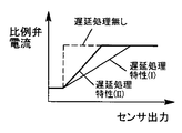
図2は、リモコン弁6,7がフルレバー操作されたときのセンサ出力と、これに基づいてコントローラ11から比例弁17に送られる電流の関係を示す。
FIG. 2 shows the relationship between the sensor output when the
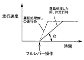
また、図3は、その結果としての時間の経過に対する走行速度の立ち上がり特性を示す。 FIG. 3 shows the rising characteristics of the traveling speed with respect to the passage of time as a result.
図2,3中、破線は遅延処理を加えない場合を示し、図2中、実線は両走行時、太線は片走行時の比例弁電流をそれぞれ示す。 2 and 3, the broken line indicates a case where no delay process is applied. In FIG. 2, the solid line indicates the proportional valve current during both travels, and the thick line indicates the proportional valve current during one travel.
遅延処理を加えない場合は、図2の破線で示すようにリモコン弁6,7が操作(走行操作)されると比例弁電流が殆ど遅れ無しで立ち上がる。
When the delay process is not applied, as shown by the broken line in FIG. 2, when the
その結果、図3の破線で示すように、フルレバー操作されてすぐ走行速度が急激に立ち上がる。 As a result, as shown by the broken line in FIG. 3, the traveling speed rapidly rises as soon as the full lever is operated.
これに対し、実施形態によると、走行時に、図2の実線及び太線で示すようにセンサ出力に対して比例弁電流を緩やかに増加させる遅延処理が行われる。 On the other hand, according to the embodiment, during traveling, a delay process is performed in which the proportional valve current is gently increased with respect to the sensor output as indicated by the solid line and the thick line in FIG.
この結果、図3の実線で示すようにフルレバー操作時点から緩やかな速度勾配αをもって走行速度が立ち上がる。すなわち、ゆっくりと発進する「走行緩発進」が行われる。 As a result, as shown by the solid line in FIG. 3, the traveling speed rises with a gentle speed gradient α from the point of full lever operation. That is, “slow start” is performed to start slowly.
これにより、たとえば上部旋回体の向きが反転した状態でオペレータが前進(または後進)のつもりで後進(または前進)操作した場合でも、わずかな移動距離で誤操作に気づき、すぐに修正操作(走行停止や後進操作)を行うことができる。 As a result, for example, even if the operator moves backward (or moves forward) with the intention of moving forward (or moving backward) with the direction of the upper turning body reversed, he notices an erroneous operation within a short moving distance, and immediately corrects it (stops running). Or reverse operation).
この場合、左右両走行モータ4,5の一方のみが駆動される片走行時(ピボットターン時)には、走行負荷が両走行時よりも格段に大きくて必要な走行トルクも大きくなるため、狙いとする応答遅れからさらに遅れた後で動き出す。
In this case, when only one of the left and right traveling
つまり、緩発進のための遅れ時間を超える発進遅れの後、急発進することになり、緩発進機能が生かせなくなる。 That is, after the start delay exceeding the delay time for slow start, the vehicle starts suddenly and the slow start function cannot be used.
そこでこの実施形態では、両走行時と片走行時とで遅延処理特性を異ならせている。 Therefore, in this embodiment, the delay processing characteristics are different for both traveling and one traveling.
すなわち、コントローラ11に、図2実線で示すように比例弁電流の立ち上がりが緩やかな両走行時用の遅延処理特性Iと、片走行時の発進遅れ分をカバーするために遅延処理特性(I)よりも比例弁電流の立ち上がりを急とする片走行時用の遅延処理特性(II)とを予め設定・記憶させておき、両走行時には遅延処理特性Iを、片走行時には遅延処理特性IIをそれぞれ選択し実行することにより、片走行時にも両走行時と同じ、図3の速度勾配αをもった緩発進機能が得られるように構成している。
That is, as shown by the solid line in FIG. 2, the
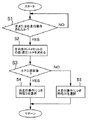
この点のコントローラ11の作用を図4のフローチャートを用いて説明する。
The operation of the
制御開始後、ステップS1で、パイロット圧センサ18,19からの出力に基づいて左または右走行操作されたか否かが判断され、NO(無操作)の場合はステップS1に戻り、YES(操作有り)の場合にステップS2に移行する。
After the control is started, it is determined in step S1 whether the left or right traveling operation has been performed based on the outputs from the
このステップS2で左右の走行パイロット圧の差(差圧)ΔPが求められ、続くステップS3でこの差圧ΔPが設定値よりも小さいか否か(両走行か片走行か)が判断される。 In step S2, a difference (differential pressure) ΔP between the left and right traveling pilot pressures is obtained. In subsequent step S3, it is determined whether or not the differential pressure ΔP is smaller than a set value (both traveling or single traveling).
ここでYES(両走行)と判断されると、ステップS4で遅延処理特性(I)が選択・実行されてステップS1に戻る。 If it is determined YES (both traveling), the delay processing characteristic (I) is selected and executed in step S4, and the process returns to step S1.
一方、NO(片走行)と判断されると、ステップS5で遅延処理特性(II)が選択・実行されてステップS1に戻る。 On the other hand, if NO (one-way running) is determined, the delay processing characteristic (II) is selected and executed in step S5, and the process returns to step S1.
このように、両走行時と片走行時とで遅延処理特性を異ならせることにより、発進速度の立ち上がりを同じとして同じ緩発進機能を確保し、誤操作を防止することができる。 In this way, by making the delay processing characteristics different between the two travelings and the one traveling, the same slow starting function can be ensured with the same starting speed rising, and erroneous operation can be prevented.
なお、両走行時及び片走行時ともフルレバー操作されることを前提とすれば、両走行時か片走行時かを判断する手法として、上記のようにパイロット差圧ΔPを求めて設定値と比較する処理に代えて、両パイロット圧センサ18,19の両方から出力があったか、片方のみから出力があったかだけによって両走行時か片走行時かを判断してもよい。
Assuming that the full lever is operated during both travel and single travel, the pilot differential pressure ΔP is obtained as described above and compared with the set value as a method for determining whether the travel is either double travel or single travel. Instead of the processing to be performed, it may be determined whether the vehicle is traveling in both directions or only in traveling, depending on whether there is an output from both
第2実施形態(図5参照)
以下の各実施形態では第1実施形態との相違点のみを説明する。
Second embodiment (see FIG. 5)
In the following embodiments, only differences from the first embodiment will be described.
第2実施形態では、左右のパイロット回路15,16にそれぞれ電磁比例減圧弁(比例弁)20,21を設け、この両比例弁20,21をコントローラ11によって個別に制御する構成をとっている。
In the second embodiment, electromagnetic proportional pressure reducing valves (proportional valves) 20 and 21 are provided in the left and
すなわち、リモコン弁6,7からコントロールバルブ8,9に送られるパイロット圧を両比例弁20,21によって制御し、両走行時と片走行時とに応じて、リモコン弁の操作に対するパイロット圧の遅延処理特性を特性(I)(II)のうちから選択するように構成している。
That is, the pilot pressure sent from the
具体的には、両走行時には両比例弁20,21が同時に図2の遅延処理特性(I)に従って制御され、片走行時には走行操作された側の比例弁20または21のみが遅延処理特性(II)に従って制御される。
Specifically, both
この構成によっても、第1実施形態と同様に、片走行時にも両走行時と同じ緩発進機能を確保するという基本的効果が得られる。 Also with this configuration, as in the first embodiment, the basic effect of ensuring the same slow start function as during both travelings can be obtained even during one traveling.
但し、第1実施形態によると、一つの比例弁17で左右のコントロールバルブ8,9を制御できるため、第2実施形態と比較してコストが安くてすむという利点がある。
However, according to the first embodiment, since the left and
第3実施形態(図6参照)
第3実施形態では、センサ出力と油圧ポンプ2の吐出量の関係について両走行時と片走行時とで異なる特性で遅延させる構成、すなわち、センサ出力に対するポンプ吐出量の立ち上がりを緩やかにし、かつ、この立ち上がりの特性を両走行時と片走行時とで異ならせる構成をとっている。
Third embodiment (see FIG. 6)
In the third embodiment, a configuration in which the relationship between the sensor output and the discharge amount of the
具体的には、コントローラ11によってレギュレータ10を制御し、図2の縦軸をポンプ吐出量とした場合に、両走行時にはポンプ吐出量を図2の実線で示す緩やかな立ち上がりで増加させるのに対し、片走行時には図2の太線で示すように両走行時よりも急な立ち上がりで増加させるように構成している。
Specifically, when the
第4実施形態(図7参照)
第4実施形態では、センサ出力とエンジン回転数の関係について両走行時と片走行時とで異なる特性で遅延させる構成、すなわち、センサ出力に対するエンジン回転数の立ち上がりを緩やかにし、かつ、この立ち上がりの特性を両走行時と片走行時とで異ならせる構成をとっている。
Fourth embodiment (see FIG. 7)
In the fourth embodiment, the relationship between the sensor output and the engine speed is delayed with different characteristics for both travel and single travel, that is, the rise of the engine speed with respect to the sensor output is moderated, and this rise The configuration is such that the characteristics are different for both traveling and single traveling.
具体的には、コントローラ11により、エンジン回転数を制御するガバナ制御部22を制御し、図2の縦軸をエンジン回転数とした場合に、両走行時にはエンジン回転数を図2の実線で示す緩やかな立ち上がりで増加させるのに対し、片走行時には図2の太線で示すように両走行時よりも急な立ち上がりで増加させるように構成している。
Specifically, the
この第3及び第4両実施形態によっても第1実施形態と基本的に同じ効果を得ることができる。 Both the third and fourth embodiments can provide basically the same effects as the first embodiment.
また、第3及び第4両実施形態によると、既存設備(レギュレータ10またはガバナ制御部22)を制御する構成であって、緩発進のために追加すべき制御設備が不要となるため、コストが安くてすむ。
In addition, according to both the third and fourth embodiments, the existing equipment (the
ところで、他の制御方式として、コントロールバルブ8,9と走行モータ4,5との間に流量制御弁を設け、走行モータ4,5に供給される流量について遅延処理を行う構成をとってもよい。
As another control method, a configuration may be adopted in which a flow rate control valve is provided between the
また、緩発進機能が不要な状況では同機能を解除できるように緩発進解除スイッチを設けてもよい。 Further, a slow start release switch may be provided so that the function can be canceled in a situation where the slow start function is unnecessary.
一方、本発明はエンジン1で油圧ポンプ2を駆動して走行モータ(油圧モータ)4,5を駆動する全油圧式のショベルに限らず、エンジン動力とバッテリ動力を併用するハイブリッドショベルや、エンジン駆動の発電機や商用電源からの電力、あるいはバッテリ電力によって走行モータ(電動機)を駆動する電動ショベルやバッテリショベルにも適用することができる。
On the other hand, the present invention is not limited to an all-hydraulic excavator in which the
また、ショベルに限らず、ショベルを母体として構成される解体機や破砕機等、他の建設機械にも適用することができる。 Further, the present invention can be applied not only to the shovel but also to other construction machines such as a dismantling machine and a crusher configured with the shovel as a base.
なお、走行モータとして電動機を用いる場合、たとえばセンサ出力に対して電動機電流を図2の遅延処理特性(I)(II)と同様に制御すればよい。 When an electric motor is used as the traveling motor, for example, the electric motor current may be controlled in the same manner as the delay processing characteristics (I) and (II) in FIG. 2 with respect to the sensor output.
1 エンジン
2 油圧ポンプ
3 パイロットポンプ
4 左右両走行モータ
6,7 走行操作手段としてのリモコン弁
8,9 コントロールバルブ
10 レギュレータ
11 制御手段としてのコントローラ
12 パイロットポンプ回路
15,16 パイロット回路
17 電磁比例減圧弁
18,19 操作検出手段としてのパイロット圧センサ
20,21 電磁比例減圧弁
22 エンジン回転数を制御するためのガバナ制御部
DESCRIPTION OF
Claims (6)
Priority Applications (1)
| Application Number | Priority Date | Filing Date | Title |
|---|---|---|---|
| JP2011075366A JP5601262B2 (en) | 2011-03-30 | 2011-03-30 | Construction machine travel control device |
Applications Claiming Priority (1)
| Application Number | Priority Date | Filing Date | Title |
|---|---|---|---|
| JP2011075366A JP5601262B2 (en) | 2011-03-30 | 2011-03-30 | Construction machine travel control device |
Publications (2)
| Publication Number | Publication Date |
|---|---|
| JP2012207491A true JP2012207491A (en) | 2012-10-25 |
| JP5601262B2 JP5601262B2 (en) | 2014-10-08 |
Family
ID=47187452
Family Applications (1)
| Application Number | Title | Priority Date | Filing Date |
|---|---|---|---|
| JP2011075366A Expired - Fee Related JP5601262B2 (en) | 2011-03-30 | 2011-03-30 | Construction machine travel control device |
Country Status (1)
| Country | Link |
|---|---|
| JP (1) | JP5601262B2 (en) |
Cited By (1)
| Publication number | Priority date | Publication date | Assignee | Title |
|---|---|---|---|---|
| WO2022209920A1 (en) * | 2021-03-29 | 2022-10-06 | 日立建機株式会社 | Work machine |
Citations (4)
| Publication number | Priority date | Publication date | Assignee | Title |
|---|---|---|---|---|
| JPH0971263A (en) * | 1995-09-05 | 1997-03-18 | Mitsubishi Agricult Mach Co Ltd | Traveling operating device of crawler type traveling vehicle |
| JPH10299034A (en) * | 1997-04-25 | 1998-11-10 | Yutani Heavy Ind Ltd | Construction machine |
| JPH10299033A (en) * | 1997-04-22 | 1998-11-10 | Kensetsusho Kanto Chiho Kensetsu Kyokucho | Traveling operation improving equipment for traveling work vehicle having upper revolving substructure and method |
| JP2000319940A (en) * | 1999-05-13 | 2000-11-21 | Kobelco Contstruction Machinery Ltd | Travel control device of construction machine |
-
2011
- 2011-03-30 JP JP2011075366A patent/JP5601262B2/en not_active Expired - Fee Related
Patent Citations (4)
| Publication number | Priority date | Publication date | Assignee | Title |
|---|---|---|---|---|
| JPH0971263A (en) * | 1995-09-05 | 1997-03-18 | Mitsubishi Agricult Mach Co Ltd | Traveling operating device of crawler type traveling vehicle |
| JPH10299033A (en) * | 1997-04-22 | 1998-11-10 | Kensetsusho Kanto Chiho Kensetsu Kyokucho | Traveling operation improving equipment for traveling work vehicle having upper revolving substructure and method |
| JPH10299034A (en) * | 1997-04-25 | 1998-11-10 | Yutani Heavy Ind Ltd | Construction machine |
| JP2000319940A (en) * | 1999-05-13 | 2000-11-21 | Kobelco Contstruction Machinery Ltd | Travel control device of construction machine |
Cited By (1)
| Publication number | Priority date | Publication date | Assignee | Title |
|---|---|---|---|---|
| WO2022209920A1 (en) * | 2021-03-29 | 2022-10-06 | 日立建機株式会社 | Work machine |
Also Published As
| Publication number | Publication date |
|---|---|
| JP5601262B2 (en) | 2014-10-08 |
Similar Documents
| Publication | Publication Date | Title |
|---|---|---|
| JP5823492B2 (en) | Excavator and control method of excavator | |
| JP4315248B2 (en) | Control device for traveling work vehicle | |
| JP5192601B1 (en) | Work vehicle and control method of work vehicle | |
| JP6495729B2 (en) | Construction machine control equipment | |
| JP5092060B1 (en) | Work vehicle and control method of work vehicle | |
| EP2749700B1 (en) | Rotation control device and construction machine including rotation control device | |
| EP3037589B1 (en) | Construction machine | |
| JP5961580B2 (en) | Drive device for work machine | |
| JP2011085159A (en) | Hydraulic driving device of working machine | |
| JP2011236751A (en) | Prime mover revolution speed control system for hydraulic construction machine | |
| CN103608570A (en) | Wheel loader and method for controlling wheel loader | |
| WO2016047167A1 (en) | Working machine display device | |
| US20150354174A1 (en) | Method for controlling driving speed of construction machinery | |
| KR20150114477A (en) | Device and method for controlling flow rate in construction machinery | |
| JP5736909B2 (en) | Pump controller for construction machinery | |
| JP6001162B2 (en) | Engine speed control device for work machines | |
| JP5601262B2 (en) | Construction machine travel control device | |
| WO2021059617A1 (en) | Construction machinery | |
| JP2015004369A (en) | Control device of hydraulic motor | |
| JP5976471B2 (en) | Excavator control method | |
| WO2020071044A1 (en) | Hydraulic shovel drive system | |
| JP2011117316A (en) | Control device of construction machine | |
| JP5177044B2 (en) | Hydraulic pump control device for construction machinery | |
| JP2006097855A (en) | Travel control device for construction machine | |
| JP2018028357A (en) | Hydraulic system for construction machine |
Legal Events
| Date | Code | Title | Description |
|---|---|---|---|
| A621 | Written request for application examination |
Free format text: JAPANESE INTERMEDIATE CODE: A621 Effective date: 20131107 |
|
| A977 | Report on retrieval |
Free format text: JAPANESE INTERMEDIATE CODE: A971007 Effective date: 20140324 |
|
| A131 | Notification of reasons for refusal |
Free format text: JAPANESE INTERMEDIATE CODE: A131 Effective date: 20140430 |
|
| A521 | Request for written amendment filed |
Free format text: JAPANESE INTERMEDIATE CODE: A523 Effective date: 20140626 |
|
| TRDD | Decision of grant or rejection written | ||
| A01 | Written decision to grant a patent or to grant a registration (utility model) |
Free format text: JAPANESE INTERMEDIATE CODE: A01 Effective date: 20140722 |
|
| A61 | First payment of annual fees (during grant procedure) |
Free format text: JAPANESE INTERMEDIATE CODE: A61 Effective date: 20140804 |
|
| R150 | Certificate of patent or registration of utility model |
Ref document number: 5601262 Country of ref document: JP Free format text: JAPANESE INTERMEDIATE CODE: R150 |
|
| LAPS | Cancellation because of no payment of annual fees |