JP2012205604A - Bioimpedance measuring device - Google Patents
Bioimpedance measuring device Download PDFInfo
- Publication number
- JP2012205604A JP2012205604A JP2011058885A JP2011058885A JP2012205604A JP 2012205604 A JP2012205604 A JP 2012205604A JP 2011058885 A JP2011058885 A JP 2011058885A JP 2011058885 A JP2011058885 A JP 2011058885A JP 2012205604 A JP2012205604 A JP 2012205604A
- Authority
- JP
- Japan
- Prior art keywords
- electromagnets
- current
- electrodes
- frequency
- bioimpedance
- Prior art date
- Legal status (The legal status is an assumption and is not a legal conclusion. Google has not performed a legal analysis and makes no representation as to the accuracy of the status listed.)
- Granted
Links
Images

Abstract
Description
本発明は、生体組織を無侵襲的に測定する技術に関する。 The present invention relates to a technique for non-invasively measuring a living tissue.
構造が複雑な生体臓器およびそれを構成する各組織は電気的な異方性を有している。電気インピーダンスの異方性の測定により、組織の構成と電気特性に関係した質の情報を得ることが期待されるため、生理学的研究、あるいは臨床応用面のおける価値が高い。 A living organ having a complicated structure and each tissue constituting the living organ have electrical anisotropy. Measurement of electrical impedance anisotropy is expected to provide quality information related to tissue composition and electrical properties, which is of great value in physiological research and clinical applications.
生体の電気インピーダンスを測定する方法として、四電極法が知られている。四電極法は、測定対象と電極との不安定な接触抵抗の影響が少ないという利点を有する反面、生体組織の形状の複雑さゆえ、生体断面のどの部分のインピーダンスを測定しているのかが判然とせず、したがって測定された結果と生理現象との対応関係の信頼性が高くないという問題がある。 A four-electrode method is known as a method for measuring the electrical impedance of a living body. While the four-electrode method has the advantage of being less affected by unstable contact resistance between the measurement object and the electrode, it is clear which part of the cross-section of the living body is being measured due to the complexity of the shape of the living tissue. Therefore, there is a problem that the correspondence between the measured result and the physiological phenomenon is not reliable.
生体の電気インピーダンスを測定する手法として、本発明者らは、特許文献1に記載の技術を提案している。しかし同文献に記載の技術では、2つの電磁石の間に生体組織を挟み込む必要があり、その用途には制限があった。
As a technique for measuring the electrical impedance of a living body, the present inventors have proposed the technique described in
本発明は係る課題に鑑みてなされたものであり、そのある態様の例示的な目的のひとつは、組織の電気インピーダンスの異方性を簡易に測定可能な装置の提供にある。 The present invention has been made in view of the above problems, and one of the exemplary purposes of an embodiment thereof is to provide an apparatus that can easily measure the electrical impedance anisotropy of a tissue.
本発明のある態様は、生体組織のインピーダンスを測定する生体インピーダンス測定装置に関する。生体インピーダンス測定装置は、渦電流発生装置と、電位差測定装置と、を備える。渦電流発生装置は、略同心円上に略等間隔に配置されたm個(mは2以上の整数)の電磁石であって、それぞれの端面が生体組織の表面に対向するように配置されるm個の電磁石を有する。各電磁石は、それぞれのコイルに流れる駆動電流に応じた渦電流を発生させる。渦電流発生装置は、生体組織内にm個の電磁石が発生させる渦電流の合成電流の方向が、時間とともに変化するように、m個の電磁石それぞれのコイルに流れる駆動電流を変化させる。電位差測定装置は、生体組織の表面上に配置された複数の測定用電極を有し、渦電流によって生体組織に発生する電位差を、2つの測定用電極のペアを用いて測定する。 One embodiment of the present invention relates to a bioimpedance measuring apparatus that measures impedance of a living tissue. The bioimpedance measurement device includes an eddy current generator and a potential difference measurement device. The eddy current generator is m electromagnets (m is an integer of 2 or more) arranged at substantially equal intervals on a substantially concentric circle, and each end surface thereof is arranged to face the surface of a living tissue. Having one electromagnet. Each electromagnet generates an eddy current corresponding to the drive current flowing through the coil. The eddy current generator changes the drive current flowing through the coils of each of the m electromagnets so that the direction of the combined current of the eddy currents generated by the m electromagnets in the living tissue changes with time. The potential difference measuring device has a plurality of measurement electrodes arranged on the surface of a living tissue, and measures a potential difference generated in the living tissue by an eddy current using a pair of two measuring electrodes.
この態様によると、複数の電磁石に駆動電流を供給することにより、生体組織には渦電流が発生する。そしてその渦電流の合成電流の流れる方向は、各電磁石のコイルに与える駆動電流の強さ、あるいは振幅の組み合わせに応じて変化させることができる。したがって生体組織内に、任意の方向で電流を流すことができ、その電流により生ずる電位差を測定用電極のペアを用いて測定することにより、生体インピーダンスの異方性を容易、および/または正確に測定することが可能となる。また、この態様によれば、複数の電磁石の間に試料を挟み込む必要が無いため、従来技術に比べて、幅広い用途に利用できる。 According to this aspect, an eddy current is generated in the living tissue by supplying a driving current to the plurality of electromagnets. The direction in which the combined current of the eddy current flows can be changed according to the strength of the drive current applied to the coils of each electromagnet or the combination of the amplitudes. Therefore, an electric current can be passed through the living tissue in an arbitrary direction, and the anisotropy of the bioimpedance can be easily and / or accurately measured by measuring a potential difference caused by the electric current using a pair of electrodes for measurement. It becomes possible to measure. Moreover, according to this aspect, since it is not necessary to pinch | interpose a sample between several electromagnets, it can utilize for a wide use compared with a prior art.
m個の電磁石それぞれのコイルには、互いに位相が略(360/m)度シフトした同一周波数の高周波の駆動電流が供給されてもよい。生体組織内には、流れる方向が駆動電流と同期して回転する合成電流が発生してもよい。 The coils of each of the m electromagnets may be supplied with a high-frequency driving current having the same frequency and having a phase shifted by approximately (360 / m) degrees. A synthetic current whose flowing direction rotates in synchronization with the drive current may be generated in the living tissue.
m=3であって、3個の電磁石は空間的に120度ずつ離れた略同心円上に配置され、各電磁石のコイルには、三相対称高周波の駆動電流が供給されてもよい。 m = 3, the three electromagnets may be arranged on substantially concentric circles that are 120 degrees apart spatially, and a three-phase symmetrical high-frequency driving current may be supplied to the coils of each electromagnet.
渦電流発生装置は、第1周波数を有する高周波キャリア電流を、第1周波数より低い第2周波数を有するm個の変調信号によって振幅変調することによりm個の駆動電流を生成し、m個の駆動電流それぞれをm個の電磁石それぞれのコイルに流すことにより、流れる方向が変調信号と同期して変化する合成電流を生体組織内に発生させてもよい。 The eddy current generator generates m drive currents by amplitude-modulating a high-frequency carrier current having a first frequency with m modulation signals having a second frequency lower than the first frequency, and generates m drive currents. A synthetic current whose flowing direction changes in synchronization with the modulation signal may be generated in the living tissue by causing each current to flow through each coil of the m electromagnets.
m=3であって、3個の電磁石は空間的に120度ずつ離れた略同心円上に配置されてもよい。m個の変調信号は、位相が互いに120度シフトした第2周波数の三相対称交流の各成分であってもよい。 m = 3, and the three electromagnets may be arranged on substantially concentric circles spatially separated by 120 degrees. The m modulation signals may be components of a three-phase symmetrical alternating current having a second frequency whose phases are shifted by 120 degrees from each other.
ある態様の電位差測定装置は、生体組織の表面上に配置された複数のキャンセル用電極をさらに有してもよい。2つの測定用電極のペアの間に発生する電位差が実質的にゼロになるように、それと対応するキャンセル用電極のペアの間に通電する高周波電流の振幅と位相を制御し、このキャンセル用電極のペア間に流れた電流値より、対応する測定用電極のペアがなす方向のインピーダンスを測定してもよい。 The potentiometric device according to an aspect may further include a plurality of cancel electrodes arranged on the surface of the biological tissue. The canceling electrode is controlled by controlling the amplitude and phase of the high-frequency current that flows between the corresponding pair of cancel electrodes so that the potential difference generated between the two pairs of measurement electrodes is substantially zero. The impedance in the direction formed by the corresponding pair of electrodes for measurement may be measured from the current value flowing between the pair.
複数の測定用電極は、m個の電磁石の端面がなす面と平行で、深度が異なる面内に設置されてもよい。 The plurality of measurement electrodes may be installed in planes that are parallel to the surface formed by the end surfaces of the m electromagnets and have different depths.
複数の測定用電極および複数のキャンセル用電極の少なくとも一方は、m個の電磁石の端面がなす面と平行で、深度が異なる面内に設置されてもよい。 At least one of the plurality of measurement electrodes and the plurality of cancellation electrodes may be disposed in a plane that is parallel to a surface formed by end surfaces of the m electromagnets and has different depths.
ある態様の生体インピーダンス測定装置は、m個の電磁石の第2の端面に、磁気的に共通にカップリングされるフェライトをさらに備えてもよい。フェライトとm個の電磁石の第2の端面の距離が調節可能であってもよい。
この態様によれば、フェライトと電磁石の距離に応じて、電磁石が発生する磁界が生体組織に浸透する深さを調節することができ、深さ方向のインピーダンス分布を測定することが可能となる。
The bioimpedance measuring device according to an aspect may further include a ferrite that is magnetically coupled in common to the second end faces of the m electromagnets. The distance between the ferrite and the second end face of the m electromagnets may be adjustable.
According to this aspect, the depth at which the magnetic field generated by the electromagnet penetrates into the living tissue can be adjusted according to the distance between the ferrite and the electromagnet, and the impedance distribution in the depth direction can be measured.
なお、以上の構成要素を任意に組み合わせたもの、あるいは本発明の表現を、方法、装置などの間で変換したものもまた、本発明の態様として有効である。 Note that any combination of the above-described components, or a conversion of the expression of the present invention between methods, apparatuses, and the like is also effective as an aspect of the present invention.
本発明のある態様によれば、生体組織の電気インピーダンスの異方性を簡易に測定できる。 According to an aspect of the present invention, the anisotropy of the electrical impedance of a living tissue can be easily measured.
以下、本発明を好適な実施の形態をもとに図面を参照しながら説明する。各図面に示される同一または同等の構成要素、部材、処理には、同一の符号を付するものとし、適宜重複した説明は省略する。また、実施の形態は、発明を限定するものではなく例示であって、実施の形態に記述されるすべての特徴やその組み合わせは、必ずしも発明の本質的なものであるとは限らない。 The present invention will be described below based on preferred embodiments with reference to the drawings. The same or equivalent components, members, and processes shown in the drawings are denoted by the same reference numerals, and repeated descriptions are omitted as appropriate. The embodiments do not limit the invention but are exemplifications, and all features and combinations thereof described in the embodiments are not necessarily essential to the invention.
(第1の実施の形態)
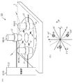
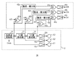
図1(a)、(b)は、第1の実施の形態に係る生体インピーダンス測定装置100の構成を示す図である。生体インピーダンス測定装置100は、生体組織のインピーダンスを測定するために利用される。図1(a)は、生体インピーダンス測定装置100の斜視図であり、図1(b)は上方断面図である。生体インピーダンス測定装置100は、主として、渦電流発生装置10および30を備える。
(First embodiment)
FIGS. 1A and 1B are diagrams illustrating a configuration of a bioimpedance measurement apparatus 100 according to the first embodiment. The bioimpedance measuring apparatus 100 is used for measuring the impedance of a living tissue. 1A is a perspective view of the bioimpedance measuring apparatus 100, and FIG. 1B is an upper cross-sectional view. The bioimpedance measuring apparatus 100 mainly includes eddy
渦電流発生装置10は、複数m個(mは2以上の整数)の電磁石M1〜Mmと、駆動部12を備える。本実施の形態ではm=3の場合を説明するが、本発明はそれに限定されるものではない。
The eddy
複数の電磁石M1〜M3は、略同心円上に略等間隔に配置される。電磁石M1〜M3それぞれの下側の端面は、測定対象の試料(生体組織ともいう)2の表面に対向するように配置される。好ましくは3個の電磁石M1〜M3は空間的に120度ずつ離れた略同心円上に配置される。各電磁石M1〜M3のコイルL1〜L3には、駆動部12から駆動電流IL1〜Il3が供給される。その結果、各電磁石M1〜M3は、試料2内に、駆動電流IL1〜IL3に応じた渦電流を発生させる。
The plurality of electromagnets M <b> 1 to M <b> 3 are arranged at substantially equal intervals on a substantially concentric circle. The lower end surface of each of the electromagnets M1 to M3 is disposed so as to face the surface of the sample (also referred to as a biological tissue) 2 to be measured. Preferably, the three electromagnets M1 to M3 are arranged on a substantially concentric circle spatially separated by 120 degrees. Drive currents I L1 to I 13 are supplied from the
駆動部12は、生体組織内に複数の電磁石M1〜M3が発生させる渦電流の合成電流の方向が、時間とともに変化するように、複数の電磁石M1〜M3それぞれのコイルL1〜L3に流れる駆動電流IL1〜IL3を変化させる。
The driving
図1(b)を参照する。試料2の表面と平行にx−y平面にとるものとする。第1の電磁石M1がθ=180度、第2の電磁石M2がθ=300度、第3の電磁石M3がθ=60度の位置に配置されているとする。このとき、原点O付近の観測点にて第1の電磁石M1が発生する渦電流J1は、コイルL1に流れる電流IL1を用いて、式(1)で与えられる。
J1=k1×IL1×h1 …(1)
ここでh1は、θ=90度の向きを有する単位ベクトルであり、k1は電磁石M1の形状、材料、コイルの巻き数、磁石と観測点の位置関係等によって定まる係数である。
Reference is made to FIG. It is assumed that the xy plane is parallel to the surface of the
J 1 = k 1 × I L1 ×
Here, h 1 is a unit vector having a direction of θ = 90 degrees, and k 1 is a coefficient determined by the shape of the electromagnet M1, the material, the number of turns of the coil, the positional relationship between the magnet and the observation point, and the like.
同様に、第2の電磁石M1が発生する渦電流J2、第3の電磁石M3が発生する渦電流J3はそれぞれ、コイルL2、L3に流れる電流IL2、IL3を用いて、式(2)、(3)で与えられる。
J2=k2×IL2×h2 …(2)
J3=k3×IL3×h3 …(3)
h2は、θ=210度の向きを有する単位ベクトル、h3はθ=330度の向きを有する単位ベクトルであり、k2、k3は、k1と同様の係数である。
Similarly, an eddy current J 2 of the second electromagnet M1 is generated, an eddy current J 3 of the third electromagnet M3 is generated respectively, using the current I L2, I L3 flowing through the coil L2, L3, formula (2 ) And (3).
J 2 = k 2 × I L2 ×
J 3 = k 3 × IL 3 × h 3 (3)
h 2 is a unit vector having a direction of θ = 210 degrees, h 3 is a unit vector having a direction of θ = 330 degrees, and k 2 and k 3 are coefficients similar to k 1 .
観測点において、3つの電磁石M1〜M3が作る渦電流J1〜J3の合成電流Jtotalは、式(4)で与えられる。
Jtotal=Σi=1:mJi=J1+J2+J3
=k1×IL1×h1+k2×IL2×h2+k3×IL3×h3 …(4)
ここで、Σi=1:mJiは、J1からJmの総和を表す。
In the observation point, resultant current J total eddy current J1~J3 make three electromagnets M1~M3 is given by Equation (4).
J total = Σ i = 1: m J i = J 1 + J 2 + J 3
= K 1 × I L1 × h 1 +
Here, Σ i = 1: m J i represents the total sum of J 1 to J m .
したがって、図1の渦電流発生装置10によれば、駆動電流IL1〜IL3を時々刻々と変化させることにより、合成電流Jtotalの向き、および/または大きさを時々刻々と変化させることができる。
Therefore, according to the
続いて、いくつかの好ましい駆動電流IL1〜IL3の発生手法を説明する。 Subsequently, a method for generating some preferable drive currents I L1 to I L3 will be described.
(第1の駆動方法)
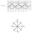
好ましい態様において、駆動部12は、電磁石M1〜M3それぞれのコイルL1〜L3に、互いに位相が略(360/m)度シフトした同一周波数の高周波の駆動電流IL1〜IL3を供給する。つまり各電磁石M1〜M3のコイルL1〜L3には、角周波数ωの三相対称高周波の駆動電流IL1〜IL3が供給される。図2(a)、(b)は、三相対称高周波の駆動電流IL1〜IL3および合成電流Jtotalの向きを示す図である。
IL1=I0・cos(ωt) …(5a)
IL2=I0・cos(ωt−2π/3) …(5b)
IL3=I0・cos(ωt−4π/3) …(5c)
(First driving method)
In a preferred embodiment, the
I L1 = I 0 · cos (ωt) (5a)
I L2 = I 0 · cos (ωt−2π / 3) (5b)
I L3 = I 0 · cos (ωt−4π / 3) (5c)
いま、観測点が3つの電磁石M1〜M3から等距離にあり、各電磁石の形状、特性が等しいとすれば、k1=k2=k3=kとみなすことができる。このとき式(4)の合成電流Jtotalは、式(6)で与えられる。
Jtotal=k×(IL1×h1+IL2×h2+IL3×h3) …(6)
Now, there from the observation point three electromagnets M1~M3 equidistant, the shape of the electromagnets, if properties are equal, can be regarded as k 1 = k 2 = k 3 = k. At this time, the combined current Jtotal of the equation (4) is given by the equation (6).
J total = k × (I L1 × h 1 + I L2 × h 2 + I L3 × h 3 ) (6)
式(6)に、式(5a)〜(5c)を代入すると、式(7)を得る。
Jtotal=k×I0×{h1・cos(ωt)+h2・cos(ωt−2π/3)+h3・cos(ωt−4π/3)} …(7)
When the expressions (5a) to (5c) are substituted into the expression (6), the expression (7) is obtained.
J total = k × I 0 × {h 1 · cos (ωt) + h 2 · cos (ωt−2π / 3) + h 3 · cos (ωt−4π / 3)} (7)
式(7)の合成電流Jtotalをx成分Jxとy成分Jyに分解すると、式(8a)、(8b)を得る。
Jx=−(3/2)k・I0・sin(ωt) (8a)
Jy=(3/2)k・I0・cos(ωt) (8b)
When the combined current J total of the equation (7) is decomposed into the x component Jx and the y component Jy, equations (8a) and (8b) are obtained.
Jx = − (3/2) k · I 0 · sin (ωt) (8a)
Jy = (3/2) k · I 0 · cos (ωt) (8b)
式(8a)、(8b)は、角周波数ωで時々刻々と回転する電流場を表しており、合成電流Jtotalの向きは、θ=ωt[rad]で与えられる。つまり、図1(a)の渦電流発生装置10によれば、生体組織内に、流れる方向が駆動電流IL1〜IL3と同期して回転する合成電流を発生させることができる。
Expressions (8a) and (8b) represent a current field that rotates every moment at the angular frequency ω, and the direction of the combined current J total is given by θ = ωt [rad]. That is, according to the
図1(a)に戻る。電位差測定装置30は、生体組織(不図示)の表面上に配置された複数の測定用電極e1〜e4を有する。複数の測定用電極e1〜e4の個数は特に限定されず、6個、あるいは8個、それ以上であってもよい。複数の測定用電極e1〜e4は、円盤(ディスク)32上に配置、固定されてもよい。
Returning to FIG. The potential
互いに対向する2つの測定用電極e1とe2はペアをなし、e3とe4はペアをなす。上述のように渦電流発生装置10によって合成電流Jtotalを発生させると、その合成電流Jtotalが、インピーダンスを有する生体組織に流れることにより、生体組織の2点間に電位差(電圧降下)が発生する。具体的には、測定用電極e1とe2のペアの間には、オームの法則によりΔVx=Rx×Jxなる電位差が発生し、測定用電極e3とe4の間には、ΔVy=Ry×Jyなる電圧降下が発生する。RxおよびRyは、x方向およびy方向のインピーダンス成分を表す。
Two measuring electrodes e1 and e2 facing each other make a pair, and e3 and e4 make a pair. When the combined current J total is generated by the
このように、実施の形態に係る生体インピーダンス測定装置100によれば、対向する測定用電極のペアの間に生ずる電位差ΔVを測定することにより、インピーダンスの異方性を測定することができる。 Thus, according to the bioelectrical impedance measuring apparatus 100 according to the embodiment, the anisotropy of impedance can be measured by measuring the potential difference ΔV generated between a pair of opposing measuring electrodes.
(第2の駆動方法)
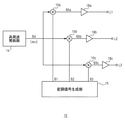
駆動部12は、第1周波数ω1を有する高周波キャリア電流を、第1周波数ω1より低い第2周波数ω2を有するm個の変調信号S1〜Smによって振幅変調することによりm個の駆動電流IL1〜ILmを生成する。そしてm個の駆動電流IL1〜ILmそれぞれを電磁石M1〜MmそれぞれのコイルL1〜Lmに流すことにより、流れる方向が変調信号S1〜Smと同期して変化する合成電流Jtotalを生体組織内に発生させる。
(Second driving method)
図3は、第2の駆動方式を行う駆動部12の構成例を示すブロック図である。高周波発振器14は、第1周波数ω1のキャリア信号S4(=cosω1t)を生成する。変調信号生成部15は、3つの変調信号S1〜S3を生成する。乗算器16a〜16cは、キャリア信号S4に、変調信号S1〜S3を掛け合わせることにより振幅変調する。アンプ18a〜18cは、乗算器16a〜16cの出力S5a〜S5cを、対応するコイルL1〜L3に供給する。
FIG. 3 is a block diagram illustrating a configuration example of the driving
好ましい態様においてm=3であって、3個の電磁石M1〜M3は空間的に120度ずつ離れた略同心円上に配置される。m個の変調信号S1〜S3は、位相が互いに120度シフトした第2周波数ω2の三相対称交流の各成分であり、式(9a)〜(9c)で与えられる。
S1=cos(ω2t) …(9a)
S2=cos(ω2t−2π/3) …(9b)
S3=cos(ω2t−4π/3) …(9c)
In a preferred embodiment, m = 3, and the three electromagnets M1 to M3 are arranged on substantially concentric circles that are spatially separated by 120 degrees. The m modulation signals S1 to S3 are the components of the three-phase symmetrical alternating current of the second frequency ω 2 whose phases are shifted from each other by 120 degrees, and are given by the equations (9a) to (9c).
S1 = cos (ω 2 t) (9a)
S2 = cos (ω 2 t−2π / 3) (9b)
S3 = cos (ω 2 t−4π / 3) (9c)
このとき、駆動電流IL1〜IL3は、式(10a)〜(10c)で与えられる。
IL1=I0・cos(ω1t)・cos(ω2t) …(10a)
IL2=I0・cos(ω1t)・cos(ω2t−2π/3) …(10b)
IL3=I0・cos(ω1t)・cos(ω2t−4π/3) …(10c)
At this time, drive currents I L1 to I L3 are given by equations (10a) to (10c).
I L1 = I 0 · cos (ω 1 t) · cos (ω 2 t) (10a)
I L2 = I 0 · cos (ω 1 t) · cos (ω 2 t−2π / 3) (10b)
I L3 = I 0 · cos (ω 1 t) · cos (ω 2 t−4π / 3) (10c)
このとき、合成電流Jtotalのx成分およびy成分はそれぞれ式(11a)、(11b)で与えられる。
Jx=−(3/2)k・I0・cos(ω1t)sin(ω2t) (11a)
Jy=(3/2)k・I0・cos(ω1t)・cos(ω2t) (11b)
At this time, the x component and the y component of the combined current J total are given by the equations (11a) and (11b), respectively.
Jx = − (3/2) k · I 0 · cos (ω 1 t) sin (ω 2 t) (11a)
Jy = (3/2) k · I 0 · cos (ω 1 t) · cos (ω 2 t) (11b)
この駆動方式では、合成電流Jtotalの向きθは、ω2t[rad]で与えられ、第2角周波数ω2と同期して回転する電流場を発生することができる。 In this driving method, the direction θ of the combined current J total is given by ω 2 t [rad], and a current field that rotates in synchronization with the second angular frequency ω 2 can be generated.
図4(a)、(b)は、図3の駆動部12の動作を示す波形図である。図4(a)に示すように変調信号S1〜S3は、式(9a)〜(9c)で与えられる信号を、量子化(サンプリング)した信号であってもよい。図4(a)では、12倍でサンプリングした信号が用いられる場合を示す。時間区間A〜Fそれぞれにおいて、変調信号S1〜S3は同じレベルをとる。図4(b)に示すように、各時間区間A〜Fにおける合成電流Jtotalの向きは、時間とともに離散的に回転させることができる。
4A and 4B are waveform diagrams showing the operation of the
なお、変調信号S1〜S3は、必ずしも離散化する必要はなく、三相交流成分をそのまま用いてもよい。
あるいは、変調信号S1〜S3の波形は、図4(a)のそれらに限定されず、たとえば、位相角θをスクランブルしてもよい。言い換えれば時間区間A〜Fの順番を任意に入れ替えてもよい。
Note that the modulation signals S1 to S3 do not necessarily need to be discretized, and three-phase AC components may be used as they are.
Alternatively, the waveforms of the modulation signals S1 to S3 are not limited to those in FIG. 4A, and for example, the phase angle θ may be scrambled. In other words, the order of the time intervals A to F may be arbitrarily changed.
(第2の実施の形態)
図5は、第2の実施の形態に係る生体インピーダンス測定装置100aの構成を示す図である。生体インピーダンス測定装置100aは、渦電流発生装置10は図1(a)と同様に構成され、電位差測定装置30aの構成が異なっている。なお、図1(a)と共通の構成については図示および説明は省略する。
(Second Embodiment)
FIG. 5 is a diagram illustrating a configuration of a
電位差測定装置30aは、複数の測定用電極e1〜e6に加えて、複数のキャンセル用電極(第2の電極)E1〜E6および制御回路34をさらに備える。キャンセル用電極E1〜E6は、測定用電極e1〜e6と同様に、生体組織の表面上に配置される。
The potential
制御回路34は、複数の測定用電極e1〜e6および複数のキャンセル用電極E1〜E6に接続される。図5では、同一放射線上に配置される電極E1、e1、e4、E4のみが、制御回路34に接続されるように描かれるが、その他の電極も同様に接続される。制御回路34は、コイルL1〜L3に駆動電流IL1〜IL3を供給する駆動部12の機能も有している。
The
図5の生体インピーダンス測定装置100aにおいては、渦電流発生装置10によって、合成電流Jtotalの方向θを変化させる。そして、合成電流Jtotalの方向θに応じて、複数の測定用電極e1〜e6のうち、合成電流Jtotalの方向θに沿って配置される測定用電極e1、e4のペア、e2とe5のペア、e3とe6のペアのいずれかを選択し、選択された測定用電極のペアに生ずる電位差を測定することにより、θ方向のインピーダンスを好適に測定することができる。
In the
測定用電極e1〜e6のみを用いた測定では、生体組織の表面付近のインピーダンスを測定できる。以下では、これにキャンセル用電極E1〜E6を組み合わせることにより、生体の表面からより深い部分のインピーダンスを測定する方法を説明する。 In the measurement using only the measurement electrodes e1 to e6, the impedance near the surface of the living tissue can be measured. Below, the method of measuring the impedance of a deeper part from the surface of a biological body by combining the cancellation electrodes E1 to E6 with this will be described.
複数のキャンセル用電極E1〜E6は、複数の測定用電極e1〜e6より外周側に、略同心円上に略等間隔に配置される。そして、互いに対応するi番目のキャンセル用電極Eiと測定用電極eiとは、同じ方向に配置される。また、対向する2つのキャンセル用電極E1とE4、E2とE5、E3とE6はそれぞれペアをなしている。生体のインピーダンスは、キャンセル用電極E1〜E6および測定用電極e1〜e6を組み合わせることにより、以下のように測定することもできる。 The plurality of cancel electrodes E1 to E6 are arranged on the outer peripheral side of the plurality of measurement electrodes e1 to e6 at substantially equal intervals on a substantially concentric circle. The i-th cancel electrode Ei and the measurement electrode ei corresponding to each other are arranged in the same direction. Further, two opposing canceling electrodes E1 and E4, E2 and E5, and E3 and E6 form a pair. The impedance of the living body can be measured as follows by combining the canceling electrodes E1 to E6 and the measuring electrodes e1 to e6.
具体的には、制御回路34は、対向する2つの測定用電極e1とe4のペアの間に発生する電位差ΔVが実質的にゼロになるように、それと対応するキャンセル用電極E1とE4のペアの間に通電する高周波電流の振幅と位相を制御する。
Specifically, the
制御回路34としては、特許文献1(特許第1909038号公報)に記載の技術を好適に用いることができる。図6は、図5の制御回路34の構成例を示す回路図である。駆動部12は、高周波発振器14、120度移相器17、19、アンプ18a〜18cを備える。高周波発振器14は、所定の周波数の高周波信号を生成する。移相器17、19は、入力された高周波信号の位相を120度シフトする。アンプ18a〜18cは、位相が120度ずつシフトした3相交流信号を、対応するコイルL1〜L3に出力する。
As the
乗算器40a〜40cはそれぞれ、測定用電極のペア(e25、e36、e41)のうち対応するひとつの電位差と、3相交流信号のうち対応するひとつを受け、それらを乗算する。整流・積分器42a〜42cはそれぞれ、対応する乗算器40の出力を整流し、積分する。乗算器44a〜44cはそれぞれ、対応する乗算器40の出力と、三相交流信号のうち対応するひとつを受け、それらを乗算する。アンプ46a〜46cはそれぞれ、対応する乗算器44の出力に応じた信号を、対応するキャンセル用電極E25,E36,E41のいずれかに出力する。制御回路34の動作の詳細については、特許文献1を参照されたい。
Each of the multipliers 40a to 40c receives one corresponding potential difference among the pair of measurement electrodes (e25, e36, e41) and one corresponding among the three-phase AC signals, and multiplies them. Each of the rectifier /
図5の生体インピーダンス測定装置100aの動作を説明する。
いま、測定用電極e1とe4のペアがなす方向θに、合成電流Jtotalが流れているものとする。このときキャンセル用電極E1とE4のペアの間に電圧を与えることにより、電磁石M1〜M3が発生する合成電流Jtotalと逆向きのキャンセル電流Jcancelが発生する。このキャンセル電流Jcancelは、生体組織の表面付近に流れるため、組織表面付近の合成電流Jtotalを、キャンセル電流Jcancelによってキャンセルすることができる。このときにキャンセル用電極E1とE4のペア間に流れる電流値は、生体組織の深い部分において、方向θのインピーダンスを示す。したがって、図5の生体インピーダンス測定装置100aによれば、キャンセル用電極に流れる電流値にもとづき、生体組織の深い部分のインピーダンスを測定することができる。
The operation of the
Assume that the combined current Jtotal flows in the direction θ formed by the pair of measurement electrodes e1 and e4. At this time, by applying a voltage between the pair of cancel electrodes E1 and E4, a cancel current J cancel in the opposite direction to the combined current J total generated by the electromagnets M1 to M3 is generated. Since the cancel current J cancel flows near the surface of the living tissue, the composite current J total near the tissue surface can be canceled by the cancel current J cancel . At this time, the current value flowing between the pair of canceling electrodes E1 and E4 shows the impedance in the direction θ in a deep portion of the living tissue. Therefore, according to the
(第3の実施の形態)
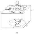
図7は、第3の実施の形態に係る生体インピーダンス測定装置100bの構成を示す図である。第3の実施の形態に係る生体インピーダンス測定装置100bは、第1または第2の実施の形態に係る生体インピーダンス測定装置と組み合わせて利用することができる。
(Third embodiment)
FIG. 7 is a diagram illustrating a configuration of a
生体インピーダンス測定装置100bは、ディスク32上に配置された複数の測定用電極および/またはキャンセル用電極に加えて、複数の測定用電極ee1、ff1、gg1〜ee6、ff6、gg6を備える。複数の測定用電極ee1、ff1、gg1〜ee6、ff6、gg6は、ディスク36上に配置される。
The
生体インピーダンス測定装置100bの動作を説明する。ディスク32とディスク36は、試料2を挟み込むように配置される。つまり、ディスク36上に配置される複数の測定用電極は、電磁石M1〜M3の下側の端面(試料側の端面)がなす面と平行で、深度が異なる面内に設置されることになる。この状態で、ディスク32によって合成電流Jtotalを発生させ、その方向を変化させながら、放射状方向に隣接する測定電極のペア(たとえばee1とff1、gg1とff1、ee4とff4、ff4とgg4)それぞれの間に生ずる電位差を測定することにより、ディスク36が設けられた深さにおけるインピーダンスを測定することができる。
The operation of the
なお、第3の実施の形態において、ディスク32側には、キャンセル用電極E1〜E6のみを設け、測定用電極e1〜e6は省略してもよい。
In the third embodiment, only the cancel electrodes E1 to E6 may be provided on the
(第4の実施の形態)
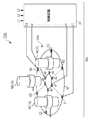
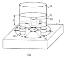
図8は、第4の実施の形態に係る生体インピーダンス測定装置100cの構成を示す図である。第4の実施の形態に係る生体インピーダンス測定装置100cは、第1または第2の実施の形態に係る生体インピーダンス測定装置と組み合わせて利用することができる。
(Fourth embodiment)
FIG. 8 is a diagram illustrating a configuration of a
生体インピーダンス測定装置100bは、フェライト50およびスペーサ52を備える。フェライト50は、複数の電磁石M1〜M3の第2の端面(試料2と反対の面)に、磁気的に共通にカップリングされる。フェライト50と、電磁石M1〜M3の第2の端面の間には、厚みdを有するスペーサ52が挿入される。スペーサ52により、フェライト50と電磁石M1〜M3の距離が調節可能となっている。
The
図7の生体インピーダンス測定装置100cによれば、スペーサ52の厚みdに応じて、試料2の内部の磁界分布を変化させることができ、その結果、合成電流Jtotalが発生する深さを変化させることができる。すなわち、フェライト50と電磁石M1〜M3の距離dを小さくした場合、磁界を試料2の浅層部を集中させることができ、浅い部分のインピーダンスを測定することができる。反対にフェライト50と電磁石M1〜M3の距離dを大きくした場合、磁界を試料2の深層部に集中させることができ、深い部分のインピーダンスを測定することができる。
According to the
実施の形態にもとづき、具体的な語句を用いて本発明を説明したが、実施の形態は、本発明の原理、応用を示しているにすぎず、実施の形態には、請求の範囲に規定された本発明の思想を逸脱しない範囲において、多くの変形例や配置の変更が認められる。 Although the present invention has been described using specific terms based on the embodiments, the embodiments only illustrate the principles and applications of the present invention, and the embodiments are defined in the claims. Many variations and modifications of the arrangement are permitted without departing from the spirit of the present invention.
100…生体インピーダンス測定装置、10…渦電流発生装置、12…駆動部、30…電位差測定装置、32…ディスク、34…制御回路、36…ディスク、40…乗算器、42…整流・積分器、44…乗算器、46…アンプ、50…フェライト、52…スペーサ、2…試料。 DESCRIPTION OF SYMBOLS 100 ... Bioimpedance measuring device, 10 ... Eddy current generator, 12 ... Drive part, 30 ... Potential difference measuring device, 32 ... Disk, 34 ... Control circuit, 36 ... Disk, 40 ... Multiplier, 42 ... Rectifier / integrator, 44 ... multiplier, 46 ... amplifier, 50 ... ferrite, 52 ... spacer, 2 ... sample.
Claims (9)
略同心円上に略等間隔に配置されたm個(mは2以上の整数)の電磁石であって、それぞれの端面が前記生体組織の表面に対向するように配置され、各電磁石がそれぞれのコイルに流れる駆動電流に応じた渦電流を発生させる、m個の電磁石を有し、前記生体組織内に前記m個の電磁石が発生させる渦電流の合成電流の方向が、時間とともに変化するように、前記m個の電磁石それぞれのコイルに流れる駆動電流を変化させる渦電流発生装置と、
生体組織の表面上に配置された複数の測定用電極を有し、前記渦電流によって前記生体組織に発生する電位差を、2つの測定用電極のペアを用いて測定する電位差測定装置と、
を備えることを特徴とする生体インピーダンス測定装置。 A bioimpedance measuring device for measuring impedance of a living tissue,
M electromagnets (m is an integer of 2 or more) arranged at substantially equal intervals on a substantially concentric circle, each end face being arranged to face the surface of the living tissue, and each electromagnet is connected to each coil. So as to change the direction of the combined current of eddy currents generated by the m electromagnets in the living tissue with time. An eddy current generator for changing the drive current flowing in the coils of each of the m electromagnets;
A potential difference measuring device having a plurality of measurement electrodes arranged on the surface of a biological tissue, and measuring a potential difference generated in the biological tissue by the eddy current using a pair of two measurement electrodes;
A bioimpedance measuring apparatus comprising:
生体組織の表面上に配置された複数のキャンセル用電極をさらに有し、
対向する2つの測定用電極のペアの間に発生する電位差が実質的にゼロになるように、それと対応するキャンセル用電極のペアの間に通電する高周波電流の振幅と位相を制御し、このキャンセル用電極のペア間に流れた電流値より、対応する測定用電極のペアがなす方向のインピーダンスを測定することを特徴とする請求項1から5のいずれかに記載の生体インピーダンス測定装置。 The potential difference measuring device includes:
It further has a plurality of cancel electrodes arranged on the surface of the biological tissue,
This cancellation is performed by controlling the amplitude and phase of the high-frequency current that flows between the corresponding pair of cancel electrodes so that the potential difference generated between the two pairs of measurement electrodes facing each other becomes substantially zero. 6. The bioimpedance measuring apparatus according to claim 1, wherein an impedance in a direction formed by a corresponding pair of measurement electrodes is measured from a current value flowing between the pair of electrodes for measurement.
Applications Claiming Priority (2)
| Application Number | Priority Date | Filing Date | Title |
|---|---|---|---|
| US32079110A | 2010-04-05 | 2010-04-05 | |
| US61/320,791 | 2010-04-05 |
Publications (2)
| Publication Number | Publication Date |
|---|---|
| JP2012205604A true JP2012205604A (en) | 2012-10-25 |
| JP5669139B2 JP5669139B2 (en) | 2015-02-12 |
Family
ID=47185974
Family Applications (1)
| Application Number | Title | Priority Date | Filing Date |
|---|---|---|---|
| JP2011058885A Expired - Fee Related JP5669139B2 (en) | 2010-04-05 | 2011-03-17 | Bioimpedance measurement device |
Country Status (1)
| Country | Link |
|---|---|
| JP (1) | JP5669139B2 (en) |
Cited By (1)
| Publication number | Priority date | Publication date | Assignee | Title |
|---|---|---|---|---|
| WO2016047515A1 (en) * | 2014-09-22 | 2016-03-31 | スカラ株式会社 | Water-content meter |
Citations (4)
| Publication number | Priority date | Publication date | Assignee | Title |
|---|---|---|---|---|
| JPH01189552A (en) * | 1988-01-25 | 1989-07-28 | Iryo Kogaku Kenkyusho:Kk | Measuring apparatus of bioimpedance |
| JPH0415036A (en) * | 1990-05-08 | 1992-01-20 | Iryo Kogaku Kenkyusho:Kk | Blood pressure measuring device |
| JPH06123731A (en) * | 1992-08-20 | 1994-05-06 | Mitsubishi Heavy Ind Ltd | Eddy-current sensor and eddy-current generation circuit |
| WO2011022068A1 (en) * | 2009-08-21 | 2011-02-24 | Rutkove Seward B | A hand-held device for electrical impedance myography |
-
2011
- 2011-03-17 JP JP2011058885A patent/JP5669139B2/en not_active Expired - Fee Related
Patent Citations (4)
| Publication number | Priority date | Publication date | Assignee | Title |
|---|---|---|---|---|
| JPH01189552A (en) * | 1988-01-25 | 1989-07-28 | Iryo Kogaku Kenkyusho:Kk | Measuring apparatus of bioimpedance |
| JPH0415036A (en) * | 1990-05-08 | 1992-01-20 | Iryo Kogaku Kenkyusho:Kk | Blood pressure measuring device |
| JPH06123731A (en) * | 1992-08-20 | 1994-05-06 | Mitsubishi Heavy Ind Ltd | Eddy-current sensor and eddy-current generation circuit |
| WO2011022068A1 (en) * | 2009-08-21 | 2011-02-24 | Rutkove Seward B | A hand-held device for electrical impedance myography |
Non-Patent Citations (3)
| Title |
|---|
| CSNJ201110036060; 竹前 忠 Tadashi Takemae: 電子情報通信学会2011年総合大会講演論文集 情報・システム1 PROCEEDINGS OF THE 2011 IEICE GENERA * |
| JPN6014041449; 竹前 忠 Tadashi Takemae: '"三相渦電流による生体組織の電気異方性の測定"' 電子情報通信学会2011年総合大会講演論文集 情報・システム1 PROCEEDINGS OF THE 2011 IEICE GENERA , p.60 * |
| JPN6014041449; 竹前 忠 Tadashi Takemae: 電子情報通信学会2011年総合大会講演論文集 情報・システム1 PROCEEDINGS OF THE 2011 IEICE GENERA * |
Cited By (1)
| Publication number | Priority date | Publication date | Assignee | Title |
|---|---|---|---|---|
| WO2016047515A1 (en) * | 2014-09-22 | 2016-03-31 | スカラ株式会社 | Water-content meter |
Also Published As
| Publication number | Publication date |
|---|---|
| JP5669139B2 (en) | 2015-02-12 |
Similar Documents
| Publication | Publication Date | Title |
|---|---|---|
| JP7004185B2 (en) | Open bore field freeline magnetic particle imaging system | |
| JP5767225B2 (en) | Apparatus and method for generating and moving a magnetic field having a magnetic field free line | |
| JP6574480B2 (en) | Spatial resolution metal detector | |
| Ma et al. | Magnetoacoustic tomography with magnetic induction: A rigorous theory | |
| MX2007005269A (en) | Reduced field distortion in medical tools. | |
| EP1615553A1 (en) | Arrangement for influencing magnetic particles | |
| Yu et al. | Performance improvement of magneto-acousto-electrical tomography for biological tissues with sinusoid-Barker coded excitation | |
| Grasland-Mongrain et al. | Imaging of shear waves induced by Lorentz force in soft tissues | |
| Li et al. | The experimental study of mouse liver in magneto-acousto-electrical tomography by scan mode | |
| CN115886773A (en) | Open type three-dimensional magnetic particle imaging device and method based on magnetic field free line | |
| JP5669139B2 (en) | Bioimpedance measurement device | |
| JP6506273B2 (en) | Shear elastic wave imaging method and apparatus for collecting flexible solid information | |
| Kaboutari et al. | Data acquisition system for MAET with magnetic field measurements | |
| Grasland-Mongrain et al. | Contactless remote induction of shear waves in soft tissues using a transcranial magnetic stimulation device | |
| US8183861B2 (en) | Arrangement including compensation for influencing and/or detecting magnetic particles in a region of action | |
| Sun et al. | Lamb wave signal selective enhancement by an improved design of meander-coil electromagnetic acoustic transducer | |
| Zhou et al. | Transducer selection and application in magnetoacoustic tomography with magnetic induction | |
| US20110273175A1 (en) | Permanent magnetic assembly for | |
| US7565189B2 (en) | MRI gradient coils with reduced neural stimulation | |
| US20100109662A1 (en) | Arrangement and method for influencing and/or detecting magnetic particles in a region of action | |
| Gerhardt et al. | Self-powered elementary hybrid magnetoelectric sensor | |
| Crowther et al. | Developments in deep brain stimulation using time dependent magnetic fields | |
| Rekhi et al. | Remote sub-wavelength focusing of ultrasonically activated Lorentz current | |
| US11382526B2 (en) | System and method for generating a traveling field free line | |
| CN117547242B (en) | Magnetic induction tomography apparatus |
Legal Events
| Date | Code | Title | Description |
|---|---|---|---|
| A621 | Written request for application examination |
Free format text: JAPANESE INTERMEDIATE CODE: A621 Effective date: 20140210 |
|
| A977 | Report on retrieval |
Free format text: JAPANESE INTERMEDIATE CODE: A971007 Effective date: 20140908 |
|
| A131 | Notification of reasons for refusal |
Free format text: JAPANESE INTERMEDIATE CODE: A131 Effective date: 20140930 |
|
| A521 | Request for written amendment filed |
Free format text: JAPANESE INTERMEDIATE CODE: A523 Effective date: 20141027 |
|
| TRDD | Decision of grant or rejection written | ||
| A01 | Written decision to grant a patent or to grant a registration (utility model) |
Free format text: JAPANESE INTERMEDIATE CODE: A01 Effective date: 20141118 |
|
| A61 | First payment of annual fees (during grant procedure) |
Free format text: JAPANESE INTERMEDIATE CODE: A61 Effective date: 20141210 |
|
| R150 | Certificate of patent or registration of utility model |
Ref document number: 5669139 Country of ref document: JP Free format text: JAPANESE INTERMEDIATE CODE: R150 |
|
| R250 | Receipt of annual fees |
Free format text: JAPANESE INTERMEDIATE CODE: R250 |
|
| R250 | Receipt of annual fees |
Free format text: JAPANESE INTERMEDIATE CODE: R250 |
|
| LAPS | Cancellation because of no payment of annual fees |