JP2012205251A - Radio communication terminal and radio communication terminal control method - Google Patents
Radio communication terminal and radio communication terminal control method Download PDFInfo
- Publication number
- JP2012205251A JP2012205251A JP2011070510A JP2011070510A JP2012205251A JP 2012205251 A JP2012205251 A JP 2012205251A JP 2011070510 A JP2011070510 A JP 2011070510A JP 2011070510 A JP2011070510 A JP 2011070510A JP 2012205251 A JP2012205251 A JP 2012205251A
- Authority
- JP
- Japan
- Prior art keywords
- wireless communication
- communication terminal
- unit
- communication unit
- connection
- Prior art date
- Legal status (The legal status is an assumption and is not a legal conclusion. Google has not performed a legal analysis and makes no representation as to the accuracy of the status listed.)
- Withdrawn
Links
Images


Classifications
-
- H—ELECTRICITY
- H04—ELECTRIC COMMUNICATION TECHNIQUE
- H04M—TELEPHONIC COMMUNICATION
- H04M1/00—Substation equipment, e.g. for use by subscribers
- H04M1/72—Mobile telephones; Cordless telephones, i.e. devices for establishing wireless links to base stations without route selection
- H04M1/724—User interfaces specially adapted for cordless or mobile telephones
- H04M1/72403—User interfaces specially adapted for cordless or mobile telephones with means for local support of applications that increase the functionality
- H04M1/72409—User interfaces specially adapted for cordless or mobile telephones with means for local support of applications that increase the functionality by interfacing with external accessories
- H04M1/72412—User interfaces specially adapted for cordless or mobile telephones with means for local support of applications that increase the functionality by interfacing with external accessories using two-way short-range wireless interfaces
-
- H—ELECTRICITY
- H04—ELECTRIC COMMUNICATION TECHNIQUE
- H04M—TELEPHONIC COMMUNICATION
- H04M2250/00—Details of telephonic subscriber devices
- H04M2250/02—Details of telephonic subscriber devices including a Bluetooth interface
-
- H—ELECTRICITY
- H04—ELECTRIC COMMUNICATION TECHNIQUE
- H04M—TELEPHONIC COMMUNICATION
- H04M2250/00—Details of telephonic subscriber devices
- H04M2250/06—Details of telephonic subscriber devices including a wireless LAN interface
Abstract
Description
本発明は、WLAN(Wireless LAN:無線LAN)などの無線通信機能を有する無線通信端末、該無線通信端末の制御方法に関する。 The present invention relates to a wireless communication terminal having a wireless communication function such as a WLAN (Wireless LAN) and a method for controlling the wireless communication terminal.
近年、WLAN、Bluetooth(ブルートゥース、登録商標)などの無線通信機能を有する無線通信端末が普及してきている。例えば、携帯電話とPDA(Personal Digital Assistant)を融合させたスマートフォンと呼ばれるものや、スマートフォンより大型のスマートパッドと呼ばれるものがそれに該当する。 In recent years, wireless communication terminals having a wireless communication function such as WLAN and Bluetooth (Bluetooth, registered trademark) have become widespread. For example, what is called a smartphone in which a mobile phone and a PDA (Personal Digital Assistant) are fused, and what is called a smart pad larger than the smartphone correspond to this.
スマートフォンやスマートパッドは、スケジュール機能や個人情報管理機能などの多種多様な機能を有し、スマートフォンにおける携帯電話機能は主にセルラーの無線通信方式に準拠する無線通信に対応している。また、スマートフォンには、セルラーの無線通信方式に準拠する無線通信に対応するルータ(以下、“3Gルータ”と呼ぶ)として動作するものもある。なお、スマートパッドにもセルラーの無線通信方式に準拠する無線通信に対応する3Gルータとして動作するものもあるが、スマートフォンに比べて絶対数は少ない。 Smartphones and smart pads have various functions such as a schedule function and a personal information management function, and the mobile phone functions in the smartphone mainly support wireless communication that conforms to the cellular wireless communication system. In addition, some smartphones operate as routers (hereinafter referred to as “3G routers”) that support wireless communication compliant with the cellular wireless communication method. Some smart pads operate as 3G routers compatible with wireless communication conforming to the cellular wireless communication method, but the absolute number is smaller than that of smartphones.
3Gルータを有しないスマートパッドでインターネットに接続する場合、WLANでアクセスポイント(以後、“第1のアクセスポイント”と呼ぶ)に接続する方法と、WLANで3Gルータを有するスマートフォンを第2のアクセスポイントとして、それに接続する方法がある。第1のアクセスポイントは有線でインターネットに接続されることから、第1のアクセスポイントに接続する場合、WLANの無線が届く通信圏内に限られる。第1のアクセスポイントに接続できる通信圏内の外に出たときには、3Gルータを有するスマートフォンを第2のアクセスポイントとしてそれに接続することで、継続してインターネットに接続することができる。 When connecting to the Internet with a smart pad that does not have a 3G router, a method of connecting to an access point (hereinafter referred to as “first access point”) by WLAN, and a smartphone having a 3G router by WLAN as a second access point There is a way to connect to it. Since the first access point is connected to the Internet by wire, the connection to the first access point is limited to the communication area within which the WLAN radio can reach. When you go out of the communication range that can be connected to the first access point, you can continue to connect to the Internet by connecting a smartphone with a 3G router as the second access point.
また、スマートフォンやスマートパッドには、WLANでアクセスポイントに接続したときや、ヘッドセットなどのブルートゥース機器を接続したときに、それぞれの接続を示すピクトを表示する機能を有するものもある。図8は、ピクト表示機能を有する従来のスマートパッド100における表示の一例を示す図である。同図に示すように、スマートパッド100がアクセスポイント110に接続した場合には、スマートパッド100の表示部101にWLANピクト200が表示される。スマートパッド100にヘッドセット120を接続した場合には、Bluetooth(登録商標)ピクト201が表示される。スマートパッド100の使用者はこれらのピクト表示を見ることで、アクセスポイント110と接続状態にあるとか、ヘッドセット120と接続状態にあるとかを認識できる。
Some smart phones and smart pads have a function of displaying a pictograph indicating each connection when connected to an access point via a WLAN or when a Bluetooth device such as a headset is connected. FIG. 8 is a diagram showing an example of display on a conventional
また、スマートパッドとスマートフォン同士がWLANで接続される場合や、ブルートゥースで接続される場合、連動して、それぞれの機器にてWLANピクト200やBluetooth(登録商標)ピクト201が表示される。
In addition, when the smart pad and the smartphone are connected by WLAN or connected by Bluetooth, the
他の機器が接続されたことを使用者に通知する類似技術として、例えば特許文献1で開示された発明(発明の名称:携帯端末及びサーバ装置)がある。この特許文献1で開示された発明では、発信先ユーザがVoLAN圏内にいるかどうかを示すアイコンと、発信先ユーザのVMO加入状態を示すアイコンとを表示するようにして、発信先ユーザが通話可能かどうか判断できるようにしている。 As a similar technique for notifying a user that another device is connected, for example, there is an invention (title of invention: portable terminal and server device) disclosed in Patent Document 1. In the invention disclosed in Patent Document 1, an icon indicating whether or not the destination user is within the VoLAN range and an icon indicating the VMO subscription status of the destination user are displayed so that the destination user can talk. It is possible to judge whether.
また、複数の機器間で連動動作する類似技術として、例えば、特許文献2で開示された発明(発明の名称:情報処理装置及び情報処理方法、情報処理システム、記録媒体、並びにプログラム)がある。この特許文献2で開示された発明では、通信手段を介して接続された複数の機器が協調動作しながら画像データを処理するようにしている。 Further, as a similar technique that operates in conjunction between a plurality of devices, for example, there is an invention (title of the invention: information processing apparatus and information processing method, information processing system, recording medium, and program) disclosed in Patent Document 2. In the invention disclosed in Patent Document 2, a plurality of devices connected via communication means process image data while performing a cooperative operation.
しかしながら、スマートパッドとスマートフォンとを無線通信でリンクさせようとした場合、どういった表示をさせるか不明確であった。つまり、スマートパッドとスマートフォンとの間の無線通信によるリンクの表示の仕方が不明であった。このことはスマートパッドとスマートフォンに限らす他の無線通信端末同士においても、これらの端末間をリンクさせようとした場合にも通ずる。 However, when trying to link the smart pad and the smartphone by wireless communication, it is unclear what kind of display is displayed. That is, how to display a link by wireless communication between the smart pad and the smartphone has been unknown. This also applies to other wireless communication terminals limited to a smart pad and a smartphone, even when trying to link these terminals.
本発明は、係る事情に鑑みてなされたものであり、2つの無線通信端末間の無線通信によるリンクを明確に表示することができる無線通信端末及び無線通信端末の制御方法を提供することを目的とする。 The present invention has been made in view of such circumstances, and an object of the present invention is to provide a wireless communication terminal capable of clearly displaying a link by wireless communication between two wireless communication terminals and a control method of the wireless communication terminal. And
本発明の無線通信端末は、第1の無線通信方式に準拠する第1の無線通信部と、第2の無線通信方式に準拠する第2の無線通信部と、表示部と、を備えた無線通信端末であって、前記第1の無線通信部及び前記第2の無線通信部により、他の無線通信端末とのペアリング処理を実行し、前記他の無線通信端末とのペアリングの完了後、前記第1の無線通信部及び前記第2の無線通信部により、前記他の無線通信端末とのリンク確立処理を実行し、前記他の無線通信端末とのリンク確立後に、前記他の無線通信端末との間で協調動作可能状態を示すピクトを前記表示部に表示し、前記第2の無線通信部による前記他の無線通信端末との接続が切断され且つ前記第1の無線通信部による前記他の無線通信端末との接続が維持されている場合は、前記表示部における前記ピクトの表示を停止し、前記第2の無線通信部による前記他の無線通信端末との接続が維持されており且つ前記第1の無線通信部による前記他の無線通信端末との接続が切断された場合は、前記表示部における前記ピクトの表示を継続する。 A wireless communication terminal according to the present invention includes a first wireless communication unit that conforms to a first wireless communication method, a second wireless communication unit that conforms to a second wireless communication method, and a display unit. A communication terminal, wherein the first wireless communication unit and the second wireless communication unit perform pairing processing with another wireless communication terminal, and after pairing with the other wireless communication terminal is completed The first wireless communication unit and the second wireless communication unit execute link establishment processing with the other wireless communication terminal, and after establishing the link with the other wireless communication terminal, the other wireless communication A pictograph indicating a cooperative operation possible state with the terminal is displayed on the display unit, the connection with the other wireless communication terminal by the second wireless communication unit is disconnected, and the first wireless communication unit If connection with other wireless communication terminals is maintained, The display of the pictograph on the display unit is stopped, the connection with the other wireless communication terminal by the second wireless communication unit is maintained, and the other wireless communication terminal by the first wireless communication unit is maintained. When the connection is disconnected, the display of the pictograph on the display unit is continued.
上記構成によれば、他の無線通信端末と第1の無線通信部及び第2の無線通信部によってペアリング処理を実行し、ペアリングの完了後、リンク確立処理を実行する。そして、リンク確立後に、他の無線通信端末との間で協調動作可能状態を示すピクトを表示部に表示する。その後、他の無線通信端末と第2の無線通信部による接続が切断され、且つ第1の無線通信部による接続が維持されている場合はピクトの表示を停止し、また、他の無線通信端末と第2の無線通信部による接続が維持され、且つ第1の無線通信部による接続が切断された場合はピクトの表示を継続する。したがって、表示部に他の無線通信端末との間の協調動作可能状態がピクトとして表示されるので、他の無線通信端末との間の無線通信によるリンク状態の表示の仕方が明確となり、本発明の無線通信端末の使用者は1つのピクトのみ見れば、2つの無線通信端末間の協調動作が有効か無効かを極めて容易に判断することができる。 According to the above configuration, the pairing process is executed by the other wireless communication terminal, the first wireless communication unit, and the second wireless communication unit, and the link establishment process is executed after the pairing is completed. And after link establishment, the pictograph which shows a cooperation operation possible state between other radio | wireless communication terminals is displayed on a display part. Thereafter, when the connection by the second wireless communication unit is disconnected from the other wireless communication terminal and the connection by the first wireless communication unit is maintained, the display of the pictograph is stopped, and the other wireless communication terminal When the connection by the second wireless communication unit is maintained and the connection by the first wireless communication unit is disconnected, the pictogram display is continued. Therefore, since the cooperative operation possible state with other wireless communication terminals is displayed as a pictograph on the display unit, the way of displaying the link state by wireless communication with other wireless communication terminals becomes clear, and the present invention The user of the wireless communication terminal can determine whether or not the cooperative operation between the two wireless communication terminals is valid or invalid by looking at only one pictograph.
上記構成において、前記第1の無線通信部はデータ通信用であり、前記第2の無線通信部は制御用である。 In the above configuration, the first wireless communication unit is for data communication, and the second wireless communication unit is for control.
上記構成において、前記第1の無線通信方式はWLANであり、前記第2の無線通信方式はブルートゥースである。 In the above configuration, the first wireless communication method is WLAN, and the second wireless communication method is Bluetooth.
本発明の無線通信端末の制御方法は、第1の無線通信方式に準拠する第1の無線通信部と、第2の無線通信方式に準拠する第2の無線通信部と、表示部と、を備えた無線通信端末の制御方法であって、前記第1の無線通信部及び前記第2の無線通信部により、他の無線通信端末とのペアリング処理を実行するステップと、前記他の無線通信端末とのペアリングの完了後、前記第1の無線通信部及び前記第2の無線通信部により、前記他の無線通信端末とのリンク確立処理を実行するステップと、前記他の無線通信端末とのリンク確立後に、前記他の無線通信端末との間で協調動作可能状態を示すピクトを前記表示部に表示するステップと、前記第2の無線通信部による前記他の無線通信端末との接続が切断され且つ前記第1の無線通信部による前記他の無線通信端末との接続が維持されている場合は、前記表示部における前記ピクトの表示を停止するステップと、前記第2の無線通信部による前記他の無線通信端末との接続が維持されており且つ前記第1の無線通信部による前記他の無線通信端末との接続が切断された場合は、前記表示部における前記ピクトの表示を継続するステップと、を備えた。 The wireless communication terminal control method of the present invention includes a first wireless communication unit that conforms to the first wireless communication method, a second wireless communication unit that conforms to the second wireless communication method, and a display unit. A method for controlling a wireless communication terminal, comprising: performing a pairing process with another wireless communication terminal by the first wireless communication unit and the second wireless communication unit; and the other wireless communication After completion of pairing with a terminal, a step of executing link establishment processing with the other wireless communication terminal by the first wireless communication unit and the second wireless communication unit; and After the link is established, a step of displaying a pictograph indicating a cooperative operation possible state with the other wireless communication terminal on the display unit, and connection with the other wireless communication terminal by the second wireless communication unit Disconnected and by the first wireless communication unit When the connection with the other wireless communication terminal is maintained, the step of stopping the display of the pictograph on the display unit and the connection with the other wireless communication terminal by the second wireless communication unit are maintained. And when the connection with the other wireless communication terminal by the first wireless communication unit is disconnected, the display of the pictograph on the display unit is continued.
上記方法によれば、他の無線通信端末と第1の無線通信部及び第2の無線通信部によってペアリング処理を実行し、ペアリングの完了後、リンク確立処理を実行する。そして、リンク確立後に、他の無線通信端末との間で協調動作可能状態を示すピクトを表示部に表示する。その後、他の無線通信端末と第2の無線通信部による接続が切断され、且つ第1の無線通信部による接続が維持されている場合はピクトの表示を停止し、また、他の無線通信端末と第2の無線通信部による接続が維持され、且つ第1の無線通信部による接続が切断された場合はピクトの表示を継続する。したがって、表示部に他の無線通信端末との間の協調動作可能状態がピクトとして表示されるので、他の無線通信端末との間の無線通信によるリンク状態の表示の仕方が明確となり、本発明の無線通信端末の使用者は1つのピクトのみ見れば、2つの無線通信端末間の協調動作が有効か無効かを極めて容易に判断することができる。 According to the above method, the pairing process is executed by the other wireless communication terminal, the first wireless communication unit, and the second wireless communication unit, and the link establishment process is executed after the pairing is completed. And after link establishment, the pictograph which shows a cooperation operation possible state between other radio | wireless communication terminals is displayed on a display part. Thereafter, when the connection by the second wireless communication unit is disconnected from the other wireless communication terminal and the connection by the first wireless communication unit is maintained, the display of the pictograph is stopped, and the other wireless communication terminal When the connection by the second wireless communication unit is maintained and the connection by the first wireless communication unit is disconnected, the pictogram display is continued. Therefore, since the cooperative operation possible state with other wireless communication terminals is displayed as a pictograph on the display unit, the way of displaying the link state by wireless communication with other wireless communication terminals becomes clear, and the present invention The user of the wireless communication terminal can determine whether or not the cooperative operation between the two wireless communication terminals is valid or invalid by looking at only one pictograph.
本発明によれば、2つの無線通信端末間の無線通信によるリンクを明確に表示することができ、本発明の無線通信端末の使用者は当該表示を一目見るだけで2つの無線通信端末間の協調動作が有効か無効かを極めて容易に判断することができる。 According to the present invention, a link by wireless communication between two wireless communication terminals can be clearly displayed, and the user of the wireless communication terminal of the present invention can easily display the link between the two wireless communication terminals with a glance. It is very easy to determine whether the cooperative operation is valid or invalid.
以下、本発明を実施するための好適な実施の形態について、図面を参照して詳細に説明する。 DESCRIPTION OF EXEMPLARY EMBODIMENTS Hereinafter, preferred embodiments for carrying out the invention will be described in detail with reference to the drawings.
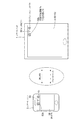
図1は、本発明の一実施の形態に係る無線通信端末及び該無線通信端末とペアリングする他の無線通信端末のリンク時の様子を示す図である。同図において、本実施の形態の無線通信端末についてはスマートパッド1と呼び、他の無線通信端末についてはスマートフォン3と呼ぶこととする。 FIG. 1 is a diagram showing a state at the time of linking a wireless communication terminal according to an embodiment of the present invention and another wireless communication terminal paired with the wireless communication terminal. In the figure, the wireless communication terminal of the present embodiment is referred to as a smart pad 1, and the other wireless communication terminals are referred to as a smartphone 3.
図1において、本実施の形態では、スマートパッド1とスマートフォン3のペアリングには、WLAN(ワイファイ(WiFi:Wireless Fidelity)とも呼ばれる)とブルートゥース(Bluetooth(登録商標))を使用している。スマートパッド1とスマートフォン3をペアリングすることで、スマートパッド1とスマートフォン3が接続できる。それにより、スマートパッド1がスマートフォン3の3Gルータ機能を利用してインターネットに接続することができる。スマートパッド1及びスマートフォン3は、インターネットを利用したデータのやりとりに必要なプロトコル(例えばTCP/IP(Transmission Control Protocol/Internet Protocol)及びHTTP(Hyper Text Transfer Protocol))を有している。 In FIG. 1, in the present embodiment, the pairing of the smart pad 1 and the smartphone 3 uses WLAN (also called WiFi (Wireless Fidelity)) and Bluetooth (Bluetooth (registered trademark)). The smart pad 1 and the smartphone 3 can be connected by pairing the smart pad 1 and the smartphone 3. Thereby, the smart pad 1 can connect to the Internet using the 3G router function of the smartphone 3. The smart pad 1 and the smartphone 3 have protocols (for example, TCP / IP (Transmission Control Protocol / Internet Protocol) and HTTP (Hyper Text Transfer Protocol)) necessary for data exchange using the Internet.
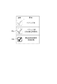
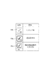
また、図1に示すように、スマートパッド1とスマートフォン3には、スマートパッド1及びスマートフォン3のそれぞれの表示部14及び表示部34の上端右側部分にWLANピクト50及びブルートゥースピクト51が表示される。また、リンクが確立していれば、機器間協調動作可能状態ピクト52b表示される。図2は、ペアリング及び機器間協調動作に関するピクトの例(1)を示す図である。同図において、ペアリングが完了したときは、ペアリング済(対向機器登録済)ピクト52aが表示される。ペアリングが完了して協調動作可能状態になったときは、機器間協調動作可能状態ピクト52bが表示される。また、図3は、ペアリング及び機器間協調動作に関するピクトの例(2)を示す図である。同図において、ペアリングが完了していないときは、ペアリング未ピクト53aが表示される。機器間協調動作がまだ確立していないときは、協調動作未ピクト53bが表示される。機器間協調動作が可能な状態になったときは、機器間協調動作可能状態ピクト53cが表示される。スマートパッド1及びスマートフォン3それぞれの使用者は、これらのピクトを見るだけでスマートパッド1とスマートフォン3の機器間協調動作が有効か無効かを判断することができる。
なお、機器間協調動作が可能な状態になったときに、協調動作未ピクト53bを消去するようにしてもよい。なお、本実施の形態では、図2に示すピクトを用いることとする。
Also, as shown in FIG. 1, the WLAN pict 50 and the Bluetooth
It should be noted that the cooperative operation non-pictogram 53b may be deleted when the inter-device cooperative operation becomes possible. In the present embodiment, the pictogram shown in FIG. 2 is used.
ここで、上述した協調動作の定義について説明する。
協調動作の定義:
(1)スマートパッド1側の操作でスマートフォン3側の機能を制御できる。
スマートフォン3側の所定の機能を起動する。例えばルータ機能が該当する。
(2)スマートフォン3側の状態が変化するとその旨をスマートパッド1側に通知する。
スマートフォン3側の状態が変化したときにその旨をスマートパッド1側に通知するか、あるいは定期的に(例えば10秒ごとに)通知する。
スマートフォン3側の状態とは、(イ)電池残量、(ロ)3Gの圏内か圏外かの情報、(ハ)メールの着信などである。
Here, the definition of the cooperative operation described above will be described.
Definition of cooperative behavior:
(1) The function on the smartphone 3 side can be controlled by the operation on the smart pad 1 side.
A predetermined function on the smartphone 3 side is activated. For example, the router function is applicable.
(2) When the state on the smartphone 3 side changes, the fact is notified to the smart pad 1 side.
When the state on the smartphone 3 side changes, the fact is notified to the smart pad 1 side or periodically (for example, every 10 seconds).
The state on the smartphone 3 side includes (a) remaining battery capacity, (b) information about whether or not within 3G, (c) incoming mail, and the like.
次に、上述したスマートパッド1及びスマートフォン3それぞれの構成及び動作について詳細に説明する。 Next, the configurations and operations of the smart pad 1 and the smartphone 3 described above will be described in detail.
(スマートパッド1の構成)
図4は、スマートパッド1の概略構成を示すブロック図である。同図において、スマートパッド1は、制御部10、記憶部11、入力部12、音声出力部13、表示部14、電源部15、電源制御部16、WLAN通信部17及びBT通信部18を有している。電源部15を除く残りの各部10,11,12,13,14,16,17及び18は内部バス20で接続されている。
(Configuration of smart pad 1)
FIG. 4 is a block diagram showing a schematic configuration of the smart pad 1. In the figure, the smart pad 1 has a
制御部10は、スマートパッド1の各部を制御するものであり、記憶部11に記憶された制御プログラムに従って動作する。記憶部11は、制御部10を動作させる制御プログラムの記憶の他、スマートパッド1で扱う各種データを記憶する。入力部12は、タッチパネルであり、表示部14の表示面の直上に配置され、使用者の手指がタッチした位置に対応する座標を座標情報として出力する。入力部12から出力された座標情報は制御部10に取り込まれる。なお、タッチパネルの方式としては、抵抗膜方式、表面弾性波方式、電磁誘導方式、静電容量方式等があり、スマートパッド1では主に静電容量方式が採用される。静電容量方式は、手指と導電膜との間における静電容量の変化を捉えて位置を検出する方式である。
The
音声出力部13は、音声を出力するものであり、図示せぬスピーカを有する。音声出力部13は、音声やミュージック等の音声ファイルの再生時には、音声ファイルから音声信号を生成してスピーカより出力する。表示部14は、液晶あるいは有機ELの表示パネルを有し、制御部10からの表示に関する指示に従って情報を表示する。電源部15は、電池(充電可能なものも含む)であり、装置各部に電力を供給する。電源制御部16は、電源部15の電池残量の監視や省電力制御を行う。WLAN通信部17は、IEEE802.11の無線通信方式に準拠する無線LAN通信を行う。BT通信部18は、IEEE802.15.1の無線通信方式に準拠し、2.45GHz帯の電波を利用して最高24Mbpsの速度で短距離無線通信を行う。
The
(スマートパッド1の動作)
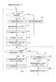
図5は、スマートパッド1の動作を説明するためのフローチャートである。同図において、スマートパッド1の制御部10は、まずペアリング操作(初期登録)が行われたかどうか判定する(ステップS1)。スマートパッド1の使用者は、ペアリングしようとするときは、スマートパッド1とスマートフォン3のそれぞれに設けられているペアリング操作ボタン(共に図示略)を同時に操作することで、スマートパッド1とスマートフォン3のそれぞれにおいて機器間協調の開始トリガがかかり、ペアリング処理が実行される。機器間協調動作時には、WLAN通信部17はデータ通信用として用いられ、BT通信部18は制御用として用いられる。
(Operation of smart pad 1)
FIG. 5 is a flowchart for explaining the operation of the smart pad 1. In the figure, the
制御部10は、ペアリング操作が行われたと判断した場合(即ちステップS1で「YES」と判断した場合)、WLAN通信部17を用いて対向機器の検索を行う(ステップS2)。ここでは対向機器はスマートフォン3であり、その検索が行われる。スマートパッド1のWLAN通信部17は、STA(Station)モードで起動して、検索パケット(Probe Request)を送信し、ネットワークの検索を行う。スマートパッド1のProbe Requestに対し、スマートフォン3のWLAN通信部38(後述する図6を参照)はProbe Responseパケットで応答することで、スマートパッド1のWLAN通信部17はスマートフォン3のWLAN通信部38が構成するネットワークを見つける。この動作は、IEEE802.11で規定されているもので公知の技術である。
When it is determined that the pairing operation has been performed (that is, when “YES” is determined in Step S1), the
制御部10は、対向機器の検索を行った後、WLAN通信部17とBT通信部18を用いて接続情報の登録を行う(ステップS3)。接続情報の登録では、(1)スマートフォン3のBluetooth(登録商標)のBD(Bluetooth(登録商標)Device)Address及びセキュリティ設定を登録する。(2)スマートフォン3のSSID(Service Set Identifier)及びセキュリティ設定を登録する。なお、SSIDは、スマートフォン3のWLAN通信部38がAPモードで起動し構築するネットワークの識別子である。ステップS1からステップS3までの処理(接続情報の登録)を行うことで、スマートパッド1とスマートフォン3のペアリングが完了する。
After searching for the opposite device, the
制御部10は、接続情報の登録を行った後、対向機器登録済ピクト(または“ペアリング済ピクト”、図2参照)52aを表示する(ステップS4)。対向機器登録済ピクト52aを表示した後、対向機器とのリンクを確立する(ステップS5)。リンクの確立においては、スマートフォン3に対して接続要求のパケットを送信し、この接続要求に対してスマートフォン3から接続可のレスポンスが返ってくる。これにより、対向機器とのリンクが確立する。リンクが確立すると、制御部10は、機器間協調動作可能状態ピクト52b(図2参照)を表示する(ステップS7)。一方、制御部10は、ステップS1の判定において、ペアリング操作が行われてないと判断すると、登録済み対象機器の検索を行い(ステップS6)、その後にステップS5の処理に移行する。
After registering the connection information, the
制御部10は、ステップS7の処理を行った後、ブルートゥースの機器間接続状態が接続から切断かどうか判定する(ステップS8)。即ち、対向機器との接続が切断されたかどうか判定する。この判定において、切断されたと判断した場合(ステップS8の判定で「YES」の場合)、機器間協調動作可能状態ピクト52bの表示を停止する(ステップS9)。次いで、対向機器登録済ピクト52aを表示する(ステップS10)。この対向機器登録済ピクト52aを表示する処理を行った後、ステップS1に戻る。
After performing the process of step S7, the
ステップS8の判定において、ブルートゥースの機器間接続状態が切断でない場合(ステップS8の判定で「NO」の場合)、WLANの機器間接続状態接続が切断かどうか判定する(ステップS11)。この判定において、切断である場合(ステップS11の判定で「YES」の場合)、機器間協調動作可能状態ピクト52bの表示を継続し(ステップS12)、ステップS13へ移行する。これに対して、ステップS11の判定において、WLANの機器間接続状態接続が切断でない場合(ステップS11の判定で「NO」の場合)、ステップS12の処理を行わず、ステップS13の処理へ移行する。ステップS12の処理を行ってステップS13に移行するか、ステップS12の処理を行うことなくステップS13に移行すると、機器間協調動作可能状態とし(ステップS13)、ステップS8に戻る。
If it is determined in step S8 that the Bluetooth device connection state is not disconnected ("NO" in step S8), it is determined whether or not the WLAN device connection state connection is disconnected (step S11). In this determination, if it is a disconnection (in the case of “YES” in the determination in step S11), the display of the inter-device cooperative operation enabled
このようにスマートパッド1では、スマートフォン3とのペアリングが完了し、接続情報の登録を行った後、対向機器登録済ピクト52aを表示して、スマートフォン3とのリンクが確立した後、機器間協調動作可能状態ピクト52bを表示する。その後、ブルートゥースの機器間接続状態が切断であれば、機器間協調動作可能状態ピクト52bの表示を停止し、対向機器登録済ピクト52aを表示する。一方、WLANの機器間接続状態が切断であれば、機器間協調動作可能状態ピクト52bの表示を継続する。
As described above, in the smart pad 1, after pairing with the smartphone 3 is completed and connection information is registered, the counter device registered
(スマートフォン3の構成)
図6は、スマートフォン3の概略構成を示すブロック図である。同図において、スマートフォン3は、制御部30、記憶部31、入力部32、音声入出力部33、表示部34、電源部35、電源制御部36、3G通信部37、WLAN通信部38及びBT通信部39を有している。電源部35を除く残りの各部30,31,32,33,34,36,37,38及び39は内部バス40で接続されている。
(Configuration of smartphone 3)
FIG. 6 is a block diagram illustrating a schematic configuration of the smartphone 3. In the figure, the smartphone 3 includes a
制御部30は、スマートフォン3の各部を制御するものであり、記憶部31に記憶された制御プログラムに従って動作する。記憶部31は、制御部30を動作させる制御プログラムの記憶の他、スマートフォン3で扱う各種データを記憶する。入力部32は、タッチパネルであり、表示部34の表示面の直上に配置され、使用者の手指がタッチした位置に対応する座標を座標情報として出力する。入力部32から出力された座標情報は制御部30に取り込まれる。なお、タッチパネルの方式としては、抵抗膜方式、表面弾性波方式、電磁誘導方式、静電容量方式等があり、スマートフォン3では主に静電容量方式が採用される。静電容量方式は、手指と導電膜との間における静電容量の変化を捉えて位置を検出する方式である。
The
音声入出力部33は、3G無線通信時の音声の入出力を行うものであり、図示せぬスピーカ及びマイクを有し、受信した通信相手の音声をスピーカから出力し、スマートフォン3の使用者の音声をマイクより入力する。また、音声入出力部33は、音声やミュージック等の音声ファイルの再生時には、音声ファイルから音声信号を生成してスピーカより出力する。表示部34は、液晶あるいは有機ELの表示パネルを有し、制御部30からの表示に関する指示に従って情報を表示する。電源部35は、電池(充電可能なものも含む)であり、装置各部に電力を供給する。電源制御部36は、電源部35の電池残量の監視や省電力制御を行う。3G通信部37は、第3世代の携帯電話方式による無線通信を行う。WLAN通信部38は、IEEE802.11の無線通信方式に準拠する無線LAN通信を行う。BT通信部39は、IEEE802.15.1の無線通信方式に準拠し、2.45GHz帯の電波を利用して最高24Mbpsの速度で短距離無線通信を行う。
The voice input / output unit 33 performs voice input / output at the time of 3G wireless communication, has a speaker and a microphone (not shown), outputs the received voice of the communication partner from the speaker, and is used by the user of the smartphone 3. Input audio from the microphone. The voice input / output unit 33 generates a voice signal from the voice file and outputs it from the speaker when playing a voice file such as voice or music. The
(スマートフォン3の動作)
図7は、スマートフォン3の動作を説明するためのフローチャートである。同図において、スマートフォン3での処理は、上述したスマートパッド1での処理と略同じであり、異なる処理についてのみ説明する。図5に示したスマートパッド1のステップS2,S3の処理が、スマートフォン3では、ステップS20,S21となる。スマートパッド1では、ステップS2でWLAN通信部17を用いて対向機器の検索を行ったが、スマートフォン3では、ステップS20で、BT通信部39を用いて対向機器の検索を行う。ここでは対向機器はスマートパッド1であり、その検索が行われる。スマートフォン3のBT通信部39は、マスターモードで起動して、問い合わせパケットを送信し、対向機器の検索を行う。スマートフォン3からの問い合わせパケットに対し、スマートパッド1のBT通信部18が問い合わせパケット応答を返すことで、スマートフォン3のBT通信部39は、スマートパッド1の存在を見つけることができる。本動作は、Bluetooth(登録商標)で規定されているもので公知の技術である。
なお、スマートパッド1がマスターモードで起動し、スマートフォン3を検索するようにしてもよい。
(Operation of smartphone 3)
FIG. 7 is a flowchart for explaining the operation of the smartphone 3. In the figure, the processing in the smartphone 3 is substantially the same as the processing in the smart pad 1 described above, and only different processing will be described. The processes in steps S2 and S3 of the smart pad 1 shown in FIG. 5 are steps S20 and S21 in the smartphone 3. In the smart pad 1, the opposite device is searched using the
The smart pad 1 may be activated in the master mode to search for the smartphone 3.
また、スマートパッド1では、ステップS3でWLAN通信部17とBT通信部18を用いて接続情報の登録を行ったが、スマートフォン3では、ステップS21で、BT通信部39を用いて接続情報の登録を行う。接続情報の登録では、スマートパッド1のBluetooth(登録商標)のBD(Bluetooth(登録商標)Device)Address及びセキュリティ設定を登録する。以上、スマートパッド1と異なる処理である。
In the smart pad 1, the connection information is registered using the
このようにスマートフォン3では、スマートパッド1とのペアリングが完了し、接続情報の登録を行った後、対向機器登録済ピクト52aを表示して、スマートパッド1とのリンクが確立した後、機器間協調動作可能状態ピクト52bを表示する。その後、ブルートゥースの機器間接続状態が切断であれば、機器間協調動作可能状態ピクト52bの表示を停止し、対向機器登録済ピクト52aを表示する。一方、WLANの機器間接続状態が切断であれば、機器間協調動作可能状態のピクト52b表示を継続する。
As described above, in the smartphone 3, after pairing with the smart pad 1 is completed and connection information is registered, the counter device registered
このように本実施の形態のスマートパッド1によれば、スマートフォン3とWLAN及びブルートゥースによってペアリング処理を実行し、ペアリングの完了後、リンク確立処理を実行する。そして、リンク確立後に、スマートフォン3との間で協調動作可能状態を示すピクト52bを表示部14に表示する。その後、スマートフォン3とブルートゥースによる接続が切断され、且つWLANによる接続が維持されている場合はピクト52bの表示を停止し、また、スマートフォン3とブルートゥースによる接続が維持され、且つWLANによる接続が切断された場合はピクト52bの表示を継続する。したがって、表示部14にスマートフォン3との間の協調動作可能状態がピクトとして表示されるので、スマートフォン3との間の無線通信によるリンク状態の表示の仕方が明確となり、スマートパッド1の使用者は1つのピクトのみ見れば、スマートフォン3との間の協調動作が有効か無効かを極めて容易に判断することができる。
Thus, according to the smart pad 1 of this Embodiment, a pairing process is performed by the smart phone 3, WLAN, and Bluetooth, and a link establishment process is performed after completion of pairing. And after link establishment, the
また、本実施の形態において、協調動作以外の目的でブルートゥースによる接続がなされる機器(たとえばヘッドセット)の接続状態を示すピクト51(ブルートゥースピクト)とは別にブルートゥースによる機器間協調動作が有効かどうかを示すピクト52b(機器間協調動作可能状態ピクト)を表示している。仮に、ブルートゥースの接続状態を示す従来のピクトのみ表示していたのでは、協調動作が有効なのか、それとも協調動作が無効なのか(協調動作以外を目的とする別の機器が接続されているだけなのか)、を使用者が判別することができない。本実施の形態によれば、機器間協調動作が有効か無効かを使用者がピクトを見ただけで判断することができる。
Also, in the present embodiment, whether or not the device-to-device cooperative operation by Bluetooth is effective separately from Pict 51 (Bluetooth Spect) indicating the connection state of a device (for example, a headset) connected by Bluetooth for purposes other than the cooperative operation. A
なお、本実施の形態では、スマートパッド1とスマートフォン3との間の機器間協調動作を、図2に示すピクトで表示するようにしたが、以下に示すように表示するようにしてもよい。
1)色の違いで表示するピクト
例えば、グレー:ペアリング未、赤:ペアリング済、緑:協調動作可能状態
2)できないことを示すピクト
例えば、前述した図3に示すように、ペアリング未→ペアリングNG、ペアリング済→協調動作NG
3)音による、ペアリング済、協調動作確立の状態通知
例えば、状態が変化したら音の長さを変える。
4)振動による、ペアリング済、協調動作確立の状態通知
例えば、状態が変化したら振動の長さを変える。
5)LED(発光ダイオード)による、ペアリング済、協調動作確立の状態通知
例えば、異なる色のLEDを点灯させる。
6)ポップアップによるダイアログ表示
例えば、協調動作確立の状態などの表示。
In the present embodiment, the inter-device cooperative operation between the smart pad 1 and the smartphone 3 is displayed as a pictograph shown in FIG. 2, but may be displayed as shown below.
1) Pictograph displayed with different colors For example, gray: not paired, red: paired, green: cooperative operation possible state 2) pictograph indicating that it is not possible For example, as shown in FIG. → Pairing NG, Pairing completed → Cooperative operation NG
3) Notification of status of paired and cooperative operation established by sound For example, if the state changes, the length of the sound is changed.
4) State notification of paired and cooperative operation establishment by vibration For example, if the state changes, the length of vibration is changed.
5) Status notification of paired and cooperative operation establishment by LED (light emitting diode) For example, LEDs of different colors are lit.
6) Dialog display by pop-up For example, display of the state of establishment of cooperative operation.
また、本実施の形態の図5又は図7で示した各処理をプログラムで記述して、磁気ディスク、光ディスク、光磁気ディスク、半導体メモリ等の記憶媒体に格納して配布することも可能である。 It is also possible to describe each processing shown in FIG. 5 or FIG. 7 of the present embodiment in a program and store it in a storage medium such as a magnetic disk, an optical disk, a magneto-optical disk, or a semiconductor memory for distribution. .
本発明は、2つの無線通信端末間の無線通信によるリンクを明確に表示することができるといった効果を有し、スマートパッドやスマートフォンと呼ばれる無線通信端末への適用が可能である。 The present invention has an effect that a link by wireless communication between two wireless communication terminals can be clearly displayed, and can be applied to a wireless communication terminal called a smart pad or a smartphone.
1 スマートパッド
3 スマートフォン
10,30 制御部
11,31 記憶部
12,32 入力部
13 音声出力部
14,34 表示部
15,35 電源部
16,36 電源制御部
17,38 WLAN通信部
18,39 BT通信部
20,40 内部バス
33 音声入出力部
37 3G通信部
50 WLANピクト
51 ブルートゥースピクト
52a 対向機器登録済(ペアリング済)ピクト
52b 機器間協調動作可能状態ピクト
53a ペアリング未ピクト
53b 協調動作未ピクト
53c 機器間協調動作可能状態ピクト
DESCRIPTION OF SYMBOLS 1 Smartpad 3
Claims (4)
前記第1の無線通信部及び前記第2の無線通信部により、他の無線通信端末とのペアリング処理を実行し、
前記他の無線通信端末とのペアリングの完了後、前記第1の無線通信部及び前記第2の無線通信部により、前記他の無線通信端末とのリンク確立処理を実行し、
前記他の無線通信端末とのリンク確立後に、前記他の無線通信端末との間で協調動作可能状態を示すピクトを前記表示部に表示し、
前記第2の無線通信部による前記他の無線通信端末との接続が切断され且つ前記第1の無線通信部による前記他の無線通信端末との接続が維持されている場合は、前記表示部における前記ピクトの表示を停止し、
前記第2の無線通信部による前記他の無線通信端末との接続が維持されており且つ前記第1の無線通信部による前記他の無線通信端末との接続が切断された場合は、前記表示部における前記ピクトの表示を継続する無線通信端末。 A wireless communication terminal comprising: a first wireless communication unit that conforms to a first wireless communication method; a second wireless communication unit that conforms to a second wireless communication method; and a display unit,
The first wireless communication unit and the second wireless communication unit perform pairing processing with another wireless communication terminal,
After completion of pairing with the other wireless communication terminal, the first wireless communication unit and the second wireless communication unit perform link establishment processing with the other wireless communication terminal,
After the link establishment with the other wireless communication terminal, a pictograph indicating a cooperative operation possible state with the other wireless communication terminal is displayed on the display unit,
In the case where the connection with the other wireless communication terminal by the second wireless communication unit is disconnected and the connection with the other wireless communication terminal by the first wireless communication unit is maintained, the display unit Stop displaying the pictogram,
When the connection with the other wireless communication terminal by the second wireless communication unit is maintained and the connection with the other wireless communication terminal by the first wireless communication unit is disconnected, the display unit A wireless communication terminal that continues displaying the pictogram in
前記第1の無線通信部はデータ通信用であり、前記第2の無線通信部は制御用である無線通信端末。 The wireless communication terminal according to claim 1,
The first wireless communication unit is for data communication, and the second wireless communication unit is a wireless communication terminal for control.
前記第1の無線通信方式はWLANであり、前記第2の無線通信方式はブルートゥースである無線通信端末。 The wireless communication terminal according to claim 1 or 2,
A wireless communication terminal in which the first wireless communication method is WLAN and the second wireless communication method is Bluetooth.
前記第1の無線通信部及び前記第2の無線通信部により、他の無線通信端末とのペアリング処理を実行するステップと、
前記他の無線通信端末とのペアリングの完了後、前記第1の無線通信部及び前記第2の無線通信部により、前記他の無線通信端末とのリンク確立処理を実行するステップと、
前記他の無線通信端末とのリンク確立後に、前記他の無線通信端末との間で協調動作可能状態を示すピクトを前記表示部に表示するステップと、
前記第2の無線通信部による前記他の無線通信端末との接続が切断され且つ前記第1の無線通信部による前記他の無線通信端末との接続が維持されている場合は、前記表示部における前記ピクトの表示を停止するステップと、
前記第2の無線通信部による前記他の無線通信端末との接続が維持されており且つ前記第1の無線通信部による前記他の無線通信端末との接続が切断された場合は、前記表示部における前記ピクトの表示を継続するステップと、を備えた無線通信端末の制御方法。 A control method for a wireless communication terminal, comprising: a first wireless communication unit that conforms to a first wireless communication method; a second wireless communication unit that conforms to a second wireless communication method; and a display unit. ,
Performing a pairing process with another wireless communication terminal by the first wireless communication unit and the second wireless communication unit;
After completion of pairing with the other wireless communication terminal, executing a link establishment process with the other wireless communication terminal by the first wireless communication unit and the second wireless communication unit;
After the link establishment with the other wireless communication terminal, displaying a pictograph indicating a cooperative operation possible state with the other wireless communication terminal on the display unit;
In the case where the connection with the other wireless communication terminal by the second wireless communication unit is disconnected and the connection with the other wireless communication terminal by the first wireless communication unit is maintained, the display unit Stopping the display of the pictograms;
When the connection with the other wireless communication terminal by the second wireless communication unit is maintained and the connection with the other wireless communication terminal by the first wireless communication unit is disconnected, the display unit A method for controlling the wireless communication terminal, comprising: continuing the display of the pictograph in FIG.
Priority Applications (2)
| Application Number | Priority Date | Filing Date | Title |
|---|---|---|---|
| JP2011070510A JP2012205251A (en) | 2011-03-28 | 2011-03-28 | Radio communication terminal and radio communication terminal control method |
| PCT/JP2012/002125 WO2012132415A1 (en) | 2011-03-28 | 2012-03-27 | Wireless communication terminal and wireless communication terminal control method |
Applications Claiming Priority (1)
| Application Number | Priority Date | Filing Date | Title |
|---|---|---|---|
| JP2011070510A JP2012205251A (en) | 2011-03-28 | 2011-03-28 | Radio communication terminal and radio communication terminal control method |
Publications (1)
| Publication Number | Publication Date |
|---|---|
| JP2012205251A true JP2012205251A (en) | 2012-10-22 |
Family
ID=46930189
Family Applications (1)
| Application Number | Title | Priority Date | Filing Date |
|---|---|---|---|
| JP2011070510A Withdrawn JP2012205251A (en) | 2011-03-28 | 2011-03-28 | Radio communication terminal and radio communication terminal control method |
Country Status (2)
| Country | Link |
|---|---|
| JP (1) | JP2012205251A (en) |
| WO (1) | WO2012132415A1 (en) |
Cited By (9)
| Publication number | Priority date | Publication date | Assignee | Title |
|---|---|---|---|---|
| WO2015097792A1 (en) * | 2013-12-25 | 2015-07-02 | 富士通株式会社 | Pairing apparatus, pairing method, and pairing program |
| WO2016067745A1 (en) * | 2014-10-31 | 2016-05-06 | ソニー株式会社 | Electronic instrument and feedback provision method |
| WO2016139968A1 (en) * | 2015-03-04 | 2016-09-09 | ソニー株式会社 | Control device, control method, and program |
| WO2016190013A1 (en) * | 2015-05-27 | 2016-12-01 | シャープ株式会社 | Mobile terminal |
| JP2017530493A (en) * | 2015-08-28 | 2017-10-12 | シャオミ・インコーポレイテッド | External device connection method and apparatus, program, and recording medium |
| US10142579B2 (en) | 2015-01-09 | 2018-11-27 | Samsung Electronics Co., Ltd. | Display apparatus and display method |
| JP2018191066A (en) * | 2017-04-28 | 2018-11-29 | パナソニックIpマネジメント株式会社 | Communication system, communication method, and communication adapter |
| JP2019185825A (en) * | 2019-07-31 | 2019-10-24 | カシオ計算機株式会社 | Information apparatus, control method, and program |
| US11157891B2 (en) | 2013-09-19 | 2021-10-26 | Casio Computer Co., Ltd. | Information device, mobile device, and wearable information device |
Family Cites Families (3)
| Publication number | Priority date | Publication date | Assignee | Title |
|---|---|---|---|---|
| JP2002118698A (en) * | 2000-10-11 | 2002-04-19 | Canon Inc | Storage medium and information processing device |
| KR100985250B1 (en) * | 2004-03-30 | 2010-10-04 | 소니 주식회사 | Interface negotiation |
| US8499079B2 (en) * | 2008-06-23 | 2013-07-30 | Apple Inc. | Apparatus and methods for providing service discovery over alternate transports |
-
2011
- 2011-03-28 JP JP2011070510A patent/JP2012205251A/en not_active Withdrawn
-
2012
- 2012-03-27 WO PCT/JP2012/002125 patent/WO2012132415A1/en active Application Filing
Cited By (16)
| Publication number | Priority date | Publication date | Assignee | Title |
|---|---|---|---|---|
| US11157891B2 (en) | 2013-09-19 | 2021-10-26 | Casio Computer Co., Ltd. | Information device, mobile device, and wearable information device |
| JPWO2015097792A1 (en) * | 2013-12-25 | 2017-03-23 | 富士通株式会社 | Pairing processing device, pairing processing method, and pairing processing program |
| US9699640B2 (en) | 2013-12-25 | 2017-07-04 | Fujitsu Limited | Pairing apparatus |
| WO2015097792A1 (en) * | 2013-12-25 | 2015-07-02 | 富士通株式会社 | Pairing apparatus, pairing method, and pairing program |
| US11726589B2 (en) | 2014-10-31 | 2023-08-15 | Sony Corporation | Electronic device and feedback providing method |
| WO2016067745A1 (en) * | 2014-10-31 | 2016-05-06 | ソニー株式会社 | Electronic instrument and feedback provision method |
| US10996776B2 (en) | 2014-10-31 | 2021-05-04 | Sony Corporation | Electronic device and feedback providing method |
| JPWO2016067745A1 (en) * | 2014-10-31 | 2017-08-10 | ソニー株式会社 | Electronic apparatus and feedback providing method |
| CN107148604A (en) * | 2014-10-31 | 2017-09-08 | 索尼公司 | Electronic installation and feedback offer method |
| US10142579B2 (en) | 2015-01-09 | 2018-11-27 | Samsung Electronics Co., Ltd. | Display apparatus and display method |
| WO2016139968A1 (en) * | 2015-03-04 | 2016-09-09 | ソニー株式会社 | Control device, control method, and program |
| WO2016190013A1 (en) * | 2015-05-27 | 2016-12-01 | シャープ株式会社 | Mobile terminal |
| JPWO2016190013A1 (en) * | 2015-05-27 | 2018-02-01 | シャープ株式会社 | Mobile terminal |
| JP2017530493A (en) * | 2015-08-28 | 2017-10-12 | シャオミ・インコーポレイテッド | External device connection method and apparatus, program, and recording medium |
| JP2018191066A (en) * | 2017-04-28 | 2018-11-29 | パナソニックIpマネジメント株式会社 | Communication system, communication method, and communication adapter |
| JP2019185825A (en) * | 2019-07-31 | 2019-10-24 | カシオ計算機株式会社 | Information apparatus, control method, and program |
Also Published As
| Publication number | Publication date |
|---|---|
| WO2012132415A1 (en) | 2012-10-04 |
Similar Documents
| Publication | Publication Date | Title |
|---|---|---|
| WO2012132415A1 (en) | Wireless communication terminal and wireless communication terminal control method | |
| US10831161B2 (en) | Method and device for sending communication message | |
| US11350200B2 (en) | Wireless audio source switching | |
| WO2018103380A1 (en) | Method for accessing wireless network, and mobile terminal | |
| JP2011146991A (en) | Radio communication device | |
| WO2018049886A1 (en) | Hotspot establishment method and terminal device | |
| US20160337279A1 (en) | Information interaction method and terminal | |
| WO2015032249A1 (en) | Method, system, device and terminal for network initialization of multimedia playing device | |
| KR20150067240A (en) | Method and system for establishing wireless fidelity direct(wfd) connection in a wfd network environment | |
| KR102361852B1 (en) | Communication apparatus, control method, and medium | |
| JP5849857B2 (en) | Near field communication device | |
| WO2019029618A1 (en) | Ims voice call network switching method, storage device and mobile terminal | |
| CN103379448A (en) | Method of reducing a waiting time when cancelling a connection and an electronic device therefor | |
| WO2015024372A1 (en) | Communication initiation method, apparatus, and mobile terminal | |
| WO2019011324A1 (en) | Method for determining access method of mobile terminal, storage medium, and mobile terminal | |
| JP5160598B2 (en) | In-vehicle terminal and pairing method in in-vehicle terminal | |
| WO2019057119A1 (en) | Mobile terminal-based wifi hotspot connection method, mobile terminal and storage medium | |
| EP3585127B1 (en) | Wireless communication-based connection method and terminal | |
| US20240113568A1 (en) | Communication pairing for telephone based on wireless charging protocol | |
| WO2015024393A1 (en) | Method, apparatus, and terminal for sending sms message | |
| WO2021239032A1 (en) | Bluetooth protocol connection method and apparatus, storage medium, and related device | |
| JP2023519942A (en) | Scheduling request configuration method, terminal and network equipment | |
| JP2014072756A (en) | Electronic apparatus, control method, and control program | |
| US10194412B2 (en) | Uplink synchronization method and terminal | |
| WO2012111341A1 (en) | Wireless communication system, wireless communication device, and wireless communication method |
Legal Events
| Date | Code | Title | Description |
|---|---|---|---|
| A300 | Application deemed to be withdrawn because no request for examination was validly filed |
Free format text: JAPANESE INTERMEDIATE CODE: A300 Effective date: 20140603 |