JP2012199951A - Techniques for high data rates with improved channel reference - Google Patents
Techniques for high data rates with improved channel reference Download PDFInfo
- Publication number
- JP2012199951A JP2012199951A JP2012109408A JP2012109408A JP2012199951A JP 2012199951 A JP2012199951 A JP 2012199951A JP 2012109408 A JP2012109408 A JP 2012109408A JP 2012109408 A JP2012109408 A JP 2012109408A JP 2012199951 A JP2012199951 A JP 2012199951A
- Authority
- JP
- Japan
- Prior art keywords
- pilot
- pilot channel
- power
- base station
- communication device
- Prior art date
- Legal status (The legal status is an assumption and is not a legal conclusion. Google has not performed a legal analysis and makes no representation as to the accuracy of the status listed.)
- Granted
Links
Images


Classifications
-
- H—ELECTRICITY
- H04—ELECTRIC COMMUNICATION TECHNIQUE
- H04W—WIRELESS COMMUNICATION NETWORKS
- H04W52/00—Power management, e.g. TPC [Transmission Power Control], power saving or power classes
- H04W52/04—TPC
- H04W52/06—TPC algorithms
- H04W52/14—Separate analysis of uplink or downlink
- H04W52/146—Uplink power control
-
- H—ELECTRICITY
- H04—ELECTRIC COMMUNICATION TECHNIQUE
- H04W—WIRELESS COMMUNICATION NETWORKS
- H04W52/00—Power management, e.g. TPC [Transmission Power Control], power saving or power classes
- H04W52/04—TPC
- H04W52/18—TPC being performed according to specific parameters
- H04W52/26—TPC being performed according to specific parameters using transmission rate or quality of service QoS [Quality of Service]
- H04W52/267—TPC being performed according to specific parameters using transmission rate or quality of service QoS [Quality of Service] taking into account the information rate
-
- H—ELECTRICITY
- H04—ELECTRIC COMMUNICATION TECHNIQUE
- H04W—WIRELESS COMMUNICATION NETWORKS
- H04W52/00—Power management, e.g. TPC [Transmission Power Control], power saving or power classes
- H04W52/04—TPC
- H04W52/30—TPC using constraints in the total amount of available transmission power
- H04W52/32—TPC of broadcast or control channels
- H04W52/325—Power control of control or pilot channels
Abstract
Description
本願は、2007年1月22日に出願され、"BOOSTED UPLINK PILOT IN W-CDMA"と題され、その全体が参照によって本願に組み込まれている米国特許仮出願60/886,085号からの35U.S.C19条の下の優先権の利益を主張する。 This application is filed on January 22, 2007 and entitled “BOOSTED UPLINK PILOT IN W-CDMA”, 35 U from US Provisional Application No. 60 / 886,085, which is incorporated herein by reference in its entirety. . S. Insist on the interests of priority under Article C19.
以下の記述は、一般に、無線通信に関し、さらに詳しくは、改善されたアップリンク・パイロットに関する。 The following description relates generally to wireless communications, and more particularly to improved uplink pilots.
無線通信システムは、様々なタイプの通信を提供するために広く展開しており、例えば、音声および/またはデータは、そのような無線通信システムによって提供されうる。一般的な無線通信システムまたはネットワークは、1または複数の共有されたリソースへ複数のユーザ・アクセスを提供することができる。例えば、これらのシステムは、利用可能なシステム・リソース(例えば帯域幅および送信電力)を共有することにより、複数のユーザとの通信をサポートすることができる多元接続システムでありうる。そのような多元接続システムの例は、符号分割多元接続(CDMA)システム、時分割多元接続(TDMA)システム、周波数分割多元接続(FDMA)システム、および直交周波数分割多元接続(OFDMA)システムを含んでいる。 Wireless communication systems are widely deployed to provide various types of communication, for example, voice and / or data can be provided by such wireless communication systems. A typical wireless communication system or network can provide multiple user access to one or more shared resources. For example, these systems can be multiple access systems that can support communication with multiple users by sharing available system resources (eg, bandwidth and transmit power). Examples of such multiple access systems include code division multiple access (CDMA) systems, time division multiple access (TDMA) systems, frequency division multiple access (FDMA) systems, and orthogonal frequency division multiple access (OFDMA) systems. Yes.
データのコーレントな復調は一般に、送信リンクによって導入されたフェーズ変化および増幅変化の起源に依存する。通常、送信リンク上のより高いデータ・レートは、良好に動作するために、より良好なフェーズ・リファレンスおよび増幅リファレンスを必要とする。このフェーズ・リファレンスおよび増幅リファレンスは、通常、パイロット・シーケンスまたはチャネルから与えられる。 Coherent demodulation of data generally depends on the origin of phase and amplification changes introduced by the transmission link. Typically, higher data rates on the transmission link require better phase and amplification references to operate well. This phase reference and amplification reference is usually given from a pilot sequence or channel.
例として、W−CDMAのアップリンクを送信する毎秒16キロ・ビット(Kb/s)のデータ・レートは、およそEc/Nt=−20dBの信号対雑音比(SNR)を持つパイロット・チャネルを必要とするだろう。一方、データ・レートが毎秒11メガ・ビット(Mbit/s)に上昇される場合、パイロットを搬送するチャネル(「専用物理制御チャネル」またはDPCCHと称される)の信号対雑音比は、およそEc/Nt=−2dBでなければならない。このようなより高いSNRは、送信機においてDPCCHの送信電力を高めることにより達成することができる。 As an example, a 16 kilobit per second (Kb / s) data rate transmitting a W-CDMA uplink requires a pilot channel with a signal-to-noise ratio (SNR) of approximately Ec / Nt = −20 dB. Would be. On the other hand, if the data rate is increased to 11 megabits per second (Mbit / s), the signal-to-noise ratio of the channel carrying the pilot (referred to as “dedicated physical control channel” or DPCCH) is approximately Ec. / Nt = -2 dB. Such a higher SNR can be achieved by increasing the DPCCH transmit power at the transmitter.
W−CDMAの現在のリリースおよび前のリリースでは、ユーザ機器(UE)は、送信データ・レートの増加に適応するためにパイロット・チャネルの送信電力を自律的に変えることはできず非効率的であった。W−CDMAシステムおよび他のシステムにおいて考慮されている将来のリリースにおいて、アップリンク(UL)においてより高いデータ・レートを導入することにより、これらの非効率性がより顕著になり、高データ・レートの通信のためのサポートを妨げている。 In the current and previous releases of W-CDMA, user equipment (UE) cannot autonomously change the pilot channel transmit power to accommodate the increase in transmit data rate, which is inefficient. there were. In future releases being considered in W-CDMA systems and other systems, introducing higher data rates in the uplink (UL) will make these inefficiencies more pronounced and higher data rates Is preventing support for communication.
現行では、高速電力制御の内部ループによって発行されるアップ・コマンドおよびダウン・コマンドは、基地局におけるパイロット・ビットに関するSNR測定に基づく。残念ながら、W−CDMAの現在のバージョンにおける基地局の現在の構成は、以下を互いに区別することはできない。a)(高データ・レート送信によって)UEによって開始されたDPCCHの送信電力における増加、b)ラジオ・リンクにおける向上(良好な経路損失、干渉レベルの低減)。何れのシナリオにおいても、システムは、パイロットのSNRが目標SNRを超えて増加されたことを観察し、ダウン・コマンドを発行する。正しい挙動は、ラジオ・リンクにおける改善があった場合にのみ基地局がダウン・コマンドを発行することである。 Currently, the up and down commands issued by the inner loop of fast power control are based on SNR measurements on pilot bits at the base station. Unfortunately, the current configuration of base stations in the current version of W-CDMA cannot distinguish the following from each other. a) Increase in transmit power of DPCCH initiated by UE (by high data rate transmission), b) Improvement in radio link (good path loss, reduced interference level). In either scenario, the system observes that the pilot SNR has increased beyond the target SNR and issues a down command. The correct behavior is that the base station issues a down command only if there is an improvement on the radio link.
さらに、現行では、DPCCHの送信電力が増加した場合において基地局がダウン・コマンドを発行すると、基地局は、高データ・レート送信のためのSNRを効率的に低減させるように動作するので、パフォーマンスが低下する。さらに、現行では、UEが高レート・パケットの送信を終了した後、パイロット送信電力における改善効果(例えば、ブースト)が取り除かれる。なぜなら、UEが、好ましくないダウン・コマンドを実行すると、パイロットは、低データ・レート送信が失敗するような低いSNRになるからである。 Further, currently, if the base station issues a down command when the DPCCH transmission power is increased, the base station operates to effectively reduce the SNR for high data rate transmission, so performance Decreases. In addition, currently the improvement effect (eg boost) in pilot transmission power is removed after the UE has finished transmitting high rate packets. This is because if the UE executes an undesired down command, the pilot will have a low SNR such that low data rate transmission fails.
前述の記載から、現行の欠点を改善するシステムおよび方法に対するニーズがあることが認識される。 From the foregoing description, it is recognized that there is a need for systems and methods that remedy current shortcomings.
以下は、1または複数の実施形態の基本的な理解を提供するために、そのような実施形態の簡略化された概要を示す。この概要は、考慮されるすべての実施形態の広範な概観でなく、すべての実施形態の重要要素や決定的要素を特定することも、任意またはすべての実施形態の範囲を線引きすることでもないことが意図される。その唯一の目的は、1または複数の実施形態の幾つかの概念を、後に示されるより詳細な記述に対する前置きとしてより簡単な形式で表すことである。 The following presents a simplified summary of such embodiments in order to provide a basic understanding of one or more embodiments. This summary is not an extensive overview of all embodiments considered, nor is it intended to identify key or critical elements of all embodiments or delineate the scope of any or all embodiments. Is intended. Its sole purpose is to present some concepts of one or more embodiments in a simplified form as a prelude to the more detailed description that is presented later.
1または複数の例示的な実施およびその対応する開示によれば、様々な局面が適応アップリンク・パイロット多重化に関連して記述される。様々な実施形態では、パイロット・チャネルで処理された許可メッセージを管理することによって、アップリンク・パイロットが高速送信のために最適化されうる。 According to one or more exemplary implementations and corresponding disclosure thereof, various aspects are described in connection with adaptive uplink pilot multiplexing. In various embodiments, uplink pilots can be optimized for high-speed transmission by managing grant messages processed on the pilot channel.
関連する局面によれば、本明細書では、パイロット効率の向上を容易にする方法が記述される。この方法は、基地局において、アップリンク・パイロット情報を決定することを含む。さらに、この方法は、アップリンク・パイロットを容易にするために、1または複数の協調する無線端末の予め定められた機能にしたがって、アップリンク・パイロット・チャネル情報を、1または複数の協調する無線端末に送信することを含む。例示的な実施において、パイロット・チャネル最適化の一部として、パイロット・チャネル・データが、協調する無線端末によって処理されるように、協調する無線端末間でパイロット・チャネル・データを通信するように動作する基地局が提供される。 According to related aspects, a method that facilitates improving pilot efficiency is described herein. The method includes determining uplink pilot information at a base station. In addition, the method may provide uplink pilot channel information to one or more coordinating radios according to a predetermined function of one or more cooperating radio terminals to facilitate uplink pilot. Including sending to the terminal. In an exemplary implementation, as part of pilot channel optimization, to communicate pilot channel data between cooperating wireless terminals such that pilot channel data is processed by the cooperating wireless terminals. An operating base station is provided.
例示的な動作において、典型的な基地局は、パイロット・チャネルをモニタし、その(信号対雑音比)レベルにおけるジャンプを検出することができる。例示的な動作において、典型的な基地局は、以前に送信されたタイム・スロットから、選択されたデシベル値以上の増加を、パイロット・レベルにおいて検出したのであれば、選択された電力制御モードで動作する。例示的に、選択された電力制御モードは、次の時間送信間隔(TTI)中、SNR測定値を無視することを含む。 In exemplary operation, a typical base station can monitor the pilot channel and detect jumps at its (signal to noise ratio) level. In an exemplary operation, a typical base station may be in a selected power control mode if it detects an increase in a pilot level above a selected decibel value from a previously transmitted time slot. Operate. Illustratively, the selected power control mode includes ignoring SNR measurements during the next time transmission interval (TTI).
別の例示的な動作では、典型的な基地局は、パイロット信号に対する典型的なブーストのレベルを知っている場合、パイロット・ブーストを補償するために、測定されたパイロットSNRを規格化するように動作することができる。例示的な実施において、この規格化されたSNRは、典型的な電力制御内部ループによって使用されうる。例示的な動作では、典型的な基地局は、ブーストしたタイム・スロット中に受信されたパイロットSNRを、ブーストしていない時間中に受信されたパイロットSNRと比較することによって、パイロット・ブーストを推定することができる。この評価の結果は、測定されたSNRを規格化するために効率的に使用されうる。 In another exemplary operation, if a typical base station knows the level of typical boost for the pilot signal, it will normalize the measured pilot SNR to compensate for the pilot boost. Can work. In an exemplary implementation, this normalized SNR may be used by a typical power control inner loop. In exemplary operation, a typical base station estimates pilot boost by comparing pilot SNR received during boosted time slots with pilot SNR received during non-boosted time slots. can do. The result of this evaluation can be used efficiently to normalize the measured SNR.
別の例示的な動作では、典型的な基地局が、ブーストしたパイロットを有する無線送信の第1のスロットにおける電力制御をディセーブルし、規格化されたSNRが以前のタイム・スロットから変わらないという仮定の下で動作する。例示的に、その後の1または複数のタイム・スロット中は、典型的な基地局が、連続したタイム・スロット間の相違を用いて、規格化されたSNRの推定値を更新することができる。規格化されたSNRは、その後、内部ループ電力制御によって使用されうる。 In another exemplary operation, a typical base station disables power control in the first slot of a radio transmission with boosted pilot, and the normalized SNR remains unchanged from the previous time slot. Operates under assumptions. Illustratively, during one or more subsequent time slots, a typical base station can update the normalized SNR estimate with the difference between successive time slots. The normalized SNR can then be used by inner loop power control.
別の例示的な動作では、典型的な基地局が、例えばW−CDMAのエンハンスト専用物理制御チャネル(E−DPDCH)のような制御チャネル上で受信された電力またはSNRを測定することができる。例示的に、典型的な基地局は、無線端末から実質的な電力の存在を検出すると、パイロットがブーストされるように動作し、選択された電力モード動作のうちの1または複数を実行する。 In another exemplary operation, a typical base station may measure the power or SNR received on a control channel, such as, for example, W-CDMA enhanced dedicated physical control channel (E-DPDCH). Illustratively, when a typical base station detects the presence of substantial power from a wireless terminal, the typical base station operates to boost the pilot and performs one or more of the selected power mode operations.
別の典型的な動作では、制御チャネルまたはデータ・チャネルの信号のうち、典型的な基地局によって信号が検出されると、電力制御は、制御チャネル上で展開されうる。例えば、W−CDMAでは、制御チャネルは、エンハンスト専用物理制御チャネル(E−DPCCH)であり、データ・チャネルは、エンハンスト専用物理データ・チャネル(E−DPDCH)でありうる。例示的に、制御チャネルのSNRは、典型的な基地局によって推定され、内部ループ電力制御のために使用される。例示的に、制御チャネルのこの推定されたSNRは、規格化されたパイロットの電力を表すように調節され、電力制御は、調節されたSNR推定値を用いて展開されうる。 In another exemplary operation, power control may be deployed on the control channel when a signal is detected by a typical base station of the control channel or data channel signals. For example, in W-CDMA, the control channel may be an enhanced dedicated physical control channel (E-DPCCH) and the data channel may be an enhanced dedicated physical data channel (E-DPDCH). Illustratively, the SNR of the control channel is estimated by a typical base station and used for inner loop power control. Illustratively, this estimated SNR of the control channel may be adjusted to represent the normalized pilot power, and power control may be deployed using the adjusted SNR estimate.
別の例示的な動作では、典型的な基地局は、すべてのTTIの開始時において電力制御をディセーブルし、ユーザ機器(UE)(例えば、1または複数の協調する無線端末)は、ブーストしたパイロットを用いて送信することができる。この典型的な基地局は、UEが、ブーストしたパイロットを用いていつ送信するのかを効果的に判定することができる。なぜなら、この典型的な基地局は、1または複数のメッセージ許可およびDTX制御によって、UE送信にわたった制御を与えることができるからである。例示的に、電力制御は、この典型的な基地局が制御チャネル(W−CDMAにおけるE−DPCCH)を復号する場合に再びイネーブルされうる。例示的な動作では、制御チャネルは、UEがパイロットをブーストしているかのみならず、典型的な基地局および1または複数の無線送信機からどのフォーマットが送信されているかを通信することができる。例示的な動作では、この典型的な基地局は、パイロットSNR推定値を規格化するために、制御チャネルの復号結果を利用することができる。 In another exemplary operation, a typical base station disables power control at the beginning of every TTI, and user equipment (UE) (eg, one or more cooperating wireless terminals) has boosted It can be transmitted using a pilot. This exemplary base station can effectively determine when the UE will transmit using the boosted pilot. This is because this exemplary base station can provide control over UE transmission with one or more message grants and DTX control. Illustratively, power control may be re-enabled when this exemplary base station decodes the control channel (E-DPCCH in W-CDMA). In an exemplary operation, the control channel can communicate which format is being transmitted from a typical base station and one or more radio transmitters, as well as whether the UE is boosting the pilot. In an exemplary operation, this exemplary base station may utilize the control channel decoding results to normalize the pilot SNR estimate.
別の例示的な実施では、典型的な基地局は、UEがパイロットをブーストさせるように動作するイベントにおいて、電力制御をディセーブルすることができる。例示的に、この典型的な基地局は、UEがパイロットをブーストさせるように動作する事例をモニタし、1または複数のUEへ許可メッセージを通信することによって、発生頻度を制限することができる。例示的な実施では、典型的な基地局は、1または複数の無線端末へ、絶対的な許可メッセージを送信し、1または複数の無線端末(例えば、UE)は、特定のTTIの間、ブーストされたパイロットを用いて高データ・レートを送信することが可能となる。 In another exemplary implementation, a typical base station can disable power control in an event where the UE operates to boost the pilot. Illustratively, this exemplary base station can monitor the case where the UE operates to boost the pilot and limit the frequency of occurrence by communicating an authorization message to one or more UEs. In an exemplary implementation, a typical base station sends an absolute grant message to one or more wireless terminals, and the one or more wireless terminals (eg, UEs) boost during a particular TTI. It is possible to transmit a high data rate using the selected pilot.
前述した目的および関連する目的を達成するために、1または複数の例示的な実施は、後に十分に説明され特許請求の範囲において特に指摘される特徴を備える。以下の記述および添付図面は、1または複数の例示的な実施のある例示的な局面をより詳細に述べる。しかしながら、これらの局面は、例示的な様々な実施の原理が適用され、かつ説明された例示的な実施がそのようなすべての局面およびそれらの等価物を含むことが意図されている様々な方式のうちのほんの幾つかを示しているに過ぎない。 To the accomplishment of the foregoing and related ends, one or more exemplary implementations include the features that are fully described later and specifically pointed out in the claims. The following description and the annexed drawings set forth in detail certain illustrative aspects of the one or more example implementations. These aspects, however, apply to various ways in which various illustrative implementation principles are applied, and the illustrative implementations described are intended to include all such aspects and their equivalents. Only a few of them are shown.
様々な実施形態が、同一要素を参照するために全体を通じて同一符番が用いられている図面を参照して説明される。以下の記載では、説明の目的のために、1または複数の実施形態の完全な理解を提供するために、多くの具体的な詳細が述べられる。しかしながら、そのような実施形態は、これら具体的な詳細無しで実現されうることが明確である。他の事例では、周知の構成およびデバイスが、1または複数の実施形態の説明を容易にするために、ブロック図形式で示される。 Various embodiments are described with reference to the drawings, wherein like reference numerals are used to refer to like elements throughout. In the following description, for the purposes of explanation, numerous specific details are set forth in order to provide a thorough understanding of one or more embodiments. However, it is clear that such embodiments can be implemented without these specific details. In other instances, well-known structures and devices are shown in block diagram form in order to facilitate describing one or more embodiments.
さらに、本発明の様々な局面が以下に述べられる。本明細書における教示は、広く様々な形態で具体化され、本明細書に記載された任意の具体的な構成および/または機能は単なる代表例であることが明白であるべきである。本明細書に記載の教示に基づいて、当業者であれば、本明細書で開示された局面は、その他任意の局面と独立して実現され、これら局面の2またはそれ以上が、様々な方式で結合されうることを認識すべきである。例えば、本明細書に記載の多くの局面を用いて装置が実現され、および/または、方法が実現されうる。さらに、本明細書で述べられた局面の1または複数に加えて、あるいはそれとは別の他の構成および/または機能を用いて装置および/または方法が実現されうる。例として、本明細書に記載の方法、デバイス、システム、および装置のうちの多くは、W−CDMA通信システムにおいてアップリンク・パイロット信号をブーストする文脈で説明される。当業者であれば、類似の技術が、他の通信環境にも適合することを認識すべきである。 In addition, various aspects of the invention are described below. It should be apparent that the teachings herein may be embodied in a wide variety of forms and that any specific configuration and / or function described herein is merely representative. Based on the teachings herein, one of ordinary skill in the art will realize the aspects disclosed herein independently of any other aspect, and two or more of these aspects may be implemented in various ways. It should be recognized that they can be combined with each other. For example, an apparatus can be implemented and / or a method can be implemented using many aspects described herein. Further, an apparatus and / or method may be implemented in addition to one or more of the aspects described herein, or using other configurations and / or functions other than that. By way of example, many of the methods, devices, systems, and apparatuses described herein are described in the context of boosting uplink pilot signals in a W-CDMA communication system. One skilled in the art should recognize that similar techniques are compatible with other communication environments.
本願で使用されるように、用語「構成要素」、「モジュール」、「システム」等は、ハードウェア、ファームウェア、ハードウェアとソフトウェアとの組み合わせ、ソフトウェア、または実行中のソフトウェア、ファームウェア、ミドルウェア、マイクロコード、および/または、これらの任意の組み合わせであるコンピュータ関連エンティティを称することが意図される。例えば、構成要素は、限定される訳ではないが、プロセッサ上で実行中のプロセス、プロセッサ、オブジェクト、実行形式、実行スレッド、プログラム、および/またはコンピュータでありうる。例示によれば、コンピュータ・デバイス上で実行中のアプリケーションと、コンピュータ・デバイスとの両方が構成要素になりえる。1または複数の構成要素は、プロセスおよび/または実行スレッド内に存在し、構成要素は、1または複数のコンピュータに局在化されるか、および/または、2またはそれ以上のコンピュータに分散されうる。さらに、これらの構成要素は、様々なデータ構造を格納して有する様々なコンピュータ読取可能媒体から実行可能である。これら構成要素は、例えば1または複数のデータ(例えば、信号によってローカル・システムや分散システム内の他の構成要素とインタラクトする1つの構成要素からのデータ、および/または、他のシステムを備えた例えばインターネットのようなネットワークを介して他の構成要素とインタラクトする1つの構成要素からのデータ)のパケットを有する信号にしたがって、ローカル処理および/またはリモート処理によって通信することができる。さらに、本明細書に記載のシステムの構成要素は、様々な局面、目標、利点等、これらに関して説明されたものを達成することを容易にするために、さらなる構成要素によって再構成および/または考慮され、さらに、当業者によって理解されるように、与えられた図面で説明された正確な構成に限定されない。 As used herein, the terms “component”, “module”, “system”, etc. refer to hardware, firmware, a combination of hardware and software, software, or running software, firmware, middleware, micro It is intended to refer to computer-related entities that are code and / or any combination thereof. For example, a component can be, but is not limited to being, a process running on a processor, a processor, an object, an executable, an execution thread, a program, and / or a computer. By way of illustration, both an application running on a computing device and the computing device can be a component. One or more components may reside within a process and / or thread of execution, and the components may be localized on one or more computers and / or distributed across two or more computers. . In addition, these components can execute from various computer readable media having various data structures stored thereon. These components may include, for example, one or more data (eg, data from one component that interacts with other components in the local system or distributed system via signals, and / or other systems, for example) It can communicate by local processing and / or remote processing according to signals having packets of data from one component interacting with other components via a network such as the Internet. Further, the components of the system described herein may be reconfigured and / or considered by additional components to facilitate achieving various aspects, goals, advantages, etc., described in these respects. And, as will be appreciated by those skilled in the art, are not limited to the exact configuration described in the given drawings.
さらに、本明細書では様々な実施形態が、無線端末またはユーザ機器(UE)に関連して記載される。無線端末またはUEはまた、システム、加入者ユニット、加入者局、モバイル局、モバイル、モバイル・デバイス、遠隔局、遠隔端末、UE、ユーザ端末、端末、無線通信デバイス、ユーザ・エージェント、あるいはユーザ・デバイスとも称されうる。無線端末またはUEは、セルラ電話、コードレス電話、セッション開始プロトコル(SIP)電話、無線ローカル・ループ(WLL)局、携帯情報端末(PDA)、無線接続機能を有するハンドヘルド・デバイス、コンピュータ・デバイス、あるいは、無線モデムに接続されたその他の処理デバイスでありうる。さらに、本明細書では、さまざまな実施形態が、基地局に関して説明される。基地局は、無線端末と通信するために利用され、アクセス・ポイント、ノードB、またはその他幾つかの専門用語で称されうる。 Moreover, various embodiments are described herein in connection with a wireless terminal or user equipment (UE). A wireless terminal or UE may also be a system, subscriber unit, subscriber station, mobile station, mobile, mobile device, remote station, remote terminal, UE, user terminal, terminal, wireless communication device, user agent, or user It may also be called a device. A wireless terminal or UE can be a cellular phone, a cordless phone, a session initiation protocol (SIP) phone, a wireless local loop (WLL) station, a personal digital assistant (PDA), a handheld device with wireless connectivity, a computer device, or Or other processing device connected to the wireless modem. Moreover, various embodiments are described herein in connection with a base station. A base station may be used to communicate with wireless terminals and may be referred to as an access point, Node B, or some other terminology.
さらに、本明細書に記載のさまざまな局面または特徴は、標準的なプログラミング技術および/またはエンジニアリング技術を用いた方法、装置、または製造物品として実現されうる。本明細書で使用される用語「製造物品」は、任意のコンピュータ読取可能デバイス、キャリア、またはメディアからアクセスすることが可能なコンピュータ・プログラムを含むことが意図される。例えば、コンピュータ読取可能媒体は、限定される訳ではないが、磁気記憶装置(例えば、ハード・ディスク、フロッピー(登録商標)ディスク、磁気ストリップ等)、光ディスク(例えば、コンパクト・ディスク(CD)、DVD等)、スマート・カード、およびフラッシュ・メモリ・デバイス(例えば、カード、スティック、キー・ドライブ等)を含みうる。さらに、本明細書に記載されたさまざまな記憶媒体は、情報を格納するための1または複数のデバイス、および/または、その他の機械読取可能媒体を表しうる。さらに、例えばセルラ・ネットワークのようなネットワークにアクセスする際、あるいは、指定された機能を実行するようにデバイスに命令する際、例えばボイス・メールの送受信に使用されるようなコンピュータ読取可能電子データまたは命令を搬送するために、搬送波が使用されうることが認識されるべきである。さらに、用語「機械読取可能媒体」は、限定する訳ではないが、無線チャネルを含むのみならず、命令群および/またはデータを格納、包含および/または伝送することが可能なその他様々な媒体を含む。もちろん、当業者であれば、多くの修正が、開示された実施形態に対して、本明細書で説明され特許請求された発明のスコープまたは精神から逸脱することなくなされることを認識するだろう。 Moreover, various aspects or features described herein may be implemented as a method, apparatus, or article of manufacture using standard programming and / or engineering techniques. The term “article of manufacture” as used herein is intended to include a computer program accessible from any computer-readable device, carrier, or media. For example, computer-readable media include, but are not limited to, magnetic storage devices (eg, hard disks, floppy disks, magnetic strips, etc.), optical disks (eg, compact disks (CD), DVDs). Etc.), smart cards, and flash memory devices (eg, cards, sticks, key drives, etc.). Additionally, various storage media described herein can represent one or more devices for storing information, and / or other machine-readable media. In addition, when accessing a network, such as a cellular network, or when instructing a device to perform a specified function, for example, computer readable electronic data such as used for sending and receiving voice mail or It should be appreciated that a carrier can be used to carry the instructions. In addition, the term “machine-readable medium” includes, but is not limited to, a variety of other media that can store, contain, and / or transmit instructions and / or data as well as including wireless channels. Including. Of course, those skilled in the art will recognize many modifications may be made to the disclosed embodiments without departing from the scope or spirit of the invention described and claimed herein. .
さらに、用語「典型的な」は、本明細書において、例、事例、または例示となることを意味するために使用される。本明細書で「典型的」と記載される設計の任意の局面は、必ずしも、その他の局面または設計よりも好適であるとか有利であると解釈される必要はない。そうではなく、これら用語の使用は典型的には、具体的な方式で本概念を示すことが意図される。本明細書で使用されるように、用語「または」は、排他的な「または」ではなく、包括的な「または」を意味することが意図される。すなわち、もしも特に指定されていないか、あるいは、文脈から明らかなように、「XはAまたはBを適用する」は、通常、包括的な順序のうちの何れかを意味することが意図されている。すなわち、XがAを適用するか、XがBを適用するか、XがAとBとの両方を適用すれば、前述した例のうちの何れかの下で、「XがAまたはBを適用する」が満足される。さらに、本明細書および特許請求の範囲で使用される冠詞「a」および「an」は、一般に、特に指定されていないか、あるいは、単数を示すものであることが文脈から明らかではない場合、「1または複数」を意味すると解釈されるべきである。 Furthermore, the term “typical” is used herein to mean serving as an example, instance, or illustration. Any aspect of a design described herein as "exemplary" is not necessarily to be construed as preferred or advantageous over other aspects or designs. Rather, the use of these terms is typically intended to illustrate this concept in a specific fashion. As used herein, the term “or” is intended to mean an inclusive “or” rather than an exclusive “or”. That is, if not specifically specified, or as is clear from the context, “X applies A or B” is usually intended to mean any of the inclusive orders Yes. That is, if X applies A, X applies B, or X applies both A and B, under either of the previous examples, “X is A or B "Apply" is satisfied. In addition, the articles “a” and “an” as used in the specification and claims are generally not specifically designated or where it is not clear from the context that they indicate the singular, It should be taken to mean “one or more”.
本明細書に記載されるように、「推論する」または「推論」なる用語は、一般に、イベントおよび/またはデータを介してキャプチャされた観察のセットからの、システム、環境、および/またはユーザに関する推論または推論処理を称する。推測は、特定の文脈または動作を特定するために適用されるか、あるいは、例えば、状態にわたった確率分布を生成することができる。推測は、確率論的であり、データおよびイベントの考慮に基づく当該状態にわたった確率分布の計算である。推測はまた、イベントおよび/またはデータのセットから、より高いレベルのイベントを構成するために適用される技術をも称しうる。そのような推測によって、観察されたイベントが、時間的に近接して相関付けられていようといまいと、観察されたイベントおよびデータが、1または幾つかのイベントおよびデータ・ソースから由来していようといまいと、観察されたイベントおよび/または格納されたイベント・データのセットから、新たなイベントまたは動作が構築される。 As described herein, the term “infer” or “inference” generally relates to a system, environment, and / or user from a set of observations captured via events and / or data. Refers to inference or inference processing. Inference can be applied to identify a specific context or action, or can generate a probability distribution over states, for example. Inference is probabilistic and is the calculation of a probability distribution over the state based on data and event considerations. Inference can also refer to techniques applied to construct a higher level event from a set of events and / or data. With such inference, whether or not the observed events are closely correlated in time, the observed events and data may come from one or several events and data sources If so, a new event or action is constructed from the observed event and / or the stored set of event data.
本明細書に記載の技術は、例えば、符号分割多元接続(CDMA)ネットワーク、時分割多元接続(TDMA)ネットワーク、周波数分割多元接続(FDMA)ネットワーク、直交FDMA(OFDMA)ネットワーク、単一キャリアFDMA(SC−FDMA)ネットワーク等のような様々な無線通信ネットワークに使用されうる。用語「ネットワーク」および「システム」は、しばしば置換可能に使用される。CDMAネットワークは、例えばユニバーサル地上ラジオ・アクセス(UTRA)、cdma2000等のようなラジオ技術を実施することができる。UTRAは、広帯域CDMA(W−CDMA)、TD−SCDMA、およびTD−CDMAを含んでいる。cdma2000は、IS−2000規格、IS−95規格、およびIS−856規格をカバーする。TDMAネットワークは、例えば、グローバル移動体通信システム(GSM(登録商標))のようなラジオ技術を実施することができる。OFDMAネットワークは、例えばエボルブドUTRA(E−UTRA)、IEEE 802.11、IEEE 802.16、IEEE 802.20、フラッシュOFDM(登録商標)等のようなラジオ技術を実施することができる。UTRA、E−UTRA、およびGSMは、ユニバーサル・モバイル・テレコミュニケーション・システム(UMTS)の一部である。ロング・ターム・エボリューション(LTE)は、E−UTRAを使用するUMTSの最新のリリースである。UTRA、E−UTRA、GSM、UMTS、およびLTEは、「第3世代パートナシップ計画(3GPP)」と命名された組織からの文書に記載されている。cdma2000は、「第3世代パートナシップ計画2」(3GPP2)と命名された組織からの文書に記載されている。これら様々なラジオ技術および規格は、当技術において周知である。明確にするために、上述した技術のある局面は、LETに当てはまるので、以下においてアップリンク・パイロット多重化の文脈で説明される。その結果、適切である場合、以下の説明の多くでは、3GPP用語が使用されうる。
The techniques described herein include, for example, code division multiple access (CDMA) networks, time division multiple access (TDMA) networks, frequency division multiple access (FDMA) networks, orthogonal FDMA (OFDMA) networks, single carrier FDMA ( It can be used for various wireless communication networks such as SC-FDMA) networks. The terms “network” and “system” are often used interchangeably. A CDMA network may implement a radio technology such as Universal Terrestrial Radio Access (UTRA), cdma2000, etc. UTRA includes Wideband CDMA (W-CDMA), TD-SCDMA, and TD-CDMA. cdma2000 covers IS-2000, IS-95, and IS-856 standards. A TDMA network may implement a radio technology such as Global System for Mobile Communications (GSM). An OFDMA network may implement radio technologies such as Evolved UTRA (E-UTRA), IEEE 802.11, IEEE 802.16, IEEE 802.20, Flash OFDM®, and the like. UTRA, E-UTRA, and GSM are part of the Universal Mobile Telecommunication System (UMTS). Long Term Evolution (LTE) is the latest release of UMTS that uses E-UTRA. UTRA, E-UTRA, GSM, UMTS, and LTE are described in documents from an organization named “3rd Generation Partnership Project (3GPP)”. cdma2000 is described in documents from an organization named “3rd
(パイロット・チャネル・ブースト)
本明細書に記載されたシステムおよび方法は、パイロット・チャネル動作を最適化するために、および、パイロット・チャネルの電力の制御が欠如して、高データ・レート送信が無駄になる事象を減らすために、現行の欠点を改めることを目的とする。例示的な実施では、UEは、パイロットを搬送するチャネルのレベルを自律的に増加(ブースト)させる能力が与えられる。例えば、W−CDMAでは、このチャネルは、専用物理制御チャネル(DPCCH)と呼ばれる。例示的な動作では、UEは、UEがデータ・チャネル上で使用する送信フォーマットに応じて、すなわち、データ・チャネルのデータ・レートに応じて、DPCCHの送信電力を増加させることができる。例示的に、データ送信の終了後、UEは、通常の電力レベルにおける動作を再開するために、DPCCHの電力を、ブーストした量減少させるように動作する。
(Pilot channel boost)
The systems and methods described herein are for optimizing pilot channel operation and reducing events where high data rate transmission is wasted due to lack of control of pilot channel power. In addition, the aim is to correct the current drawbacks. In an exemplary implementation, the UE is given the ability to autonomously increase (boost) the level of the channel carrying the pilot. For example, in W-CDMA, this channel is called a dedicated physical control channel (DPCCH). In an exemplary operation, the UE may increase the transmit power of the DPCCH according to the transmission format that the UE uses on the data channel, i.e., depending on the data rate of the data channel. Illustratively, after the end of data transmission, the UE operates to reduce the DPCCH power by a boosted amount in order to resume operation at normal power levels.
別の例示的な実施では、例えばW−CDMAにおけるエンハンスト専用物理制御チャネルのような制御チャネルのレベルが増加(ブースト)されうる。例示的な動作では、まずE−DPCCHが復号され、次に、E−DPCCHをパイロット・リファレンスに変換するために、選択されたスキームにしたがって変調シンボルがフリップされる。この例示的な動作ではその後、E−DPCCHがDPCCHと結合され、例えばDPDCHのような他のチャネルを復号するための改善されたフェーズ・リファレンスおよび増幅リファレンスが提供される。 In another exemplary implementation, the level of a control channel, such as an enhanced dedicated physical control channel in W-CDMA, may be increased (boosted). In an exemplary operation, the E-DPCCH is first decoded and then the modulation symbols are flipped according to the selected scheme to convert the E-DPCCH to a pilot reference. In this exemplary operation, the E-DPCCH is then combined with the DPCCH to provide an improved phase reference and amplification reference for decoding other channels such as DPDCH.
例示的な実施では、伝搬チャネルおよび干渉レベルの変動による受信機におけるパイロット・チャネルSNRの急激な変動を緩和するために、高速電力制御が適用されうる。例示的に、W−CDMAのアップリンクにおいて現在使用されているような高速電力制御は一般に、2つのループ、すなわち、内部ループおよび外部ループに依存する。例示的な動作では、内部ループは、典型的な基地局(例えば、ノードB、RNC、またはその他のインフラストラクチャ要素)が、パイロット・ビットのSNRを測定し、測定されたSNRを目標SNRと比較して、この比較に基づいて、測定されたSNRを目標SNRの近くに維持できるようにアップ・コマンドまたはダウン・コマンドを1または複数の協調する無線端末(例えば、ユーザ機器−UE)へ発行する動作を実行することができる。例示的に、UEは、アップ・コマンドを受信すると、そのチャネルの電力を、ステップ・サイズ増加させることができる。例示的に、UEが、協調セルのアクティブ・セット内のセルのうちの何れか(例えば、協調する基地局)からダウン・コマンドを受信した場合、チャネルの電力を、ステップ・サイズ低減させることができる。 In an exemplary implementation, fast power control may be applied to mitigate rapid fluctuations in the pilot channel SNR at the receiver due to propagation channel and interference level fluctuations. Illustratively, high speed power control as currently used in W-CDMA uplink generally relies on two loops: an inner loop and an outer loop. In an exemplary operation, the inner loop causes a typical base station (eg, Node B, RNC, or other infrastructure element) to measure the pilot bit SNR and compare the measured SNR to the target SNR. Then, based on this comparison, issue an up command or a down command to one or more cooperating wireless terminals (eg, user equipment-UE) so that the measured SNR can be kept close to the target SNR. The action can be performed. Illustratively, when a UE receives an up command, the UE may increase its channel power by a step size. Illustratively, if the UE receives a down command from any of the cells in the active set of cooperating cells (eg, cooperating base stations), the channel power may be reduced by a step size. it can.
しかしながら、現行では、高速電力制御の内部ループによって発行されるアップ・コマンドおよびダウン・コマンドは、一般に、基地局におけるパイロット・ビットにおけるSNR測定に基づく。W−CDMA基地局は、下記a)、b)を互いを区別することができない。a)UEによって発行されたDPCCHの送信電力における増加。なぜなら、UEは高データ・レート送信を送るからである。b)ラジオ・リンクにおける改善(良好な経路損失、干渉レベルの低減、その他)。現行では、基地局は、両ケースにおいて、パイロットのSNRが目標SNRよりも増えたことを観察し、ダウン・コマンドを発行する。しかしながら、望ましい挙動は、基地局が、ケース(b)の場合にのみダウン・コマンドを発行することであろう。 Currently, however, the up and down commands issued by the fast power control inner loop are generally based on SNR measurements on pilot bits at the base station. The W-CDMA base station cannot distinguish the following a) and b) from each other. a) Increase in transmit power of DPCCH issued by UE. This is because the UE sends a high data rate transmission. b) Improvements in the radio link (good path loss, reduced interference level, etc.). Currently, the base station observes that in both cases the pilot SNR has increased above the target SNR and issues a down command. However, the desired behavior would be that the base station issues a down command only in case (b).
ケース(a)の場合にダウン・コマンドを発行することによって、基地局は、高データ・レート送信のためのSNRを低下させ、もって、パフォーマンスを低下させる。さらに、UEが高レート・パケットを送信し終えた後、パイロット送信電力のブーストが止まるだろう。それゆえ、UEが望ましくないダウン・コマンドを実行すると、パイロットは、低いSNRになるので、あらゆる低いデータ・レート送信が失敗しうる。 By issuing a down command in case (a), the base station reduces the SNR for high data rate transmission, thereby reducing performance. Furthermore, after the UE has finished sending high rate packets, the pilot transmission power boost will stop. Therefore, if the UE performs an undesirable down command, the pilot will have a low SNR, so any low data rate transmission may fail.
現行の内部ループの欠点を克服するために、本明細書に記載のシステムおよび方法は、典型的な基地局が効率的にパイロットを測定し、そのレベルにおけるジャンプを検出する無線通信システムを提供する。例示的な動作では、典型的な基地局が、パイロット・レベルにおいて、以前に観察されたタイム・スロットからΔdBよりも多く増加したことを検出すると、典型的な基地局は、ブーストしたパイロットを示すデータを格納する。例示的な動作では、典型的な基地局が、電力制御ループを従来方式で動作させ、以下の例示的な動作のうちの1または複数を実行して、可能なブーストしたパイロットを検出し、以下の例示的な動作によって説明されるようなモードのうちの1つで動作するように電力制御を切り換える。 To overcome the shortcomings of current inner loops, the systems and methods described herein provide a wireless communication system in which a typical base station efficiently measures pilots and detects jumps at that level. . In an exemplary operation, when a typical base station detects that the pilot level has increased more than ΔdB from a previously observed time slot, the typical base station indicates a boosted pilot. Store the data. In an exemplary operation, an exemplary base station operates a power control loop in a conventional manner and performs one or more of the following exemplary operations to detect possible boosted pilots, and The power control is switched to operate in one of the modes as described by the exemplary operation.
例示的な動作では、典型的な基地局は、パイロット・チャネルをモニタし、その(信号対雑音比)レベルにおけるジャンプを検出することができる。この例示的な動作では、典型的な基地局が、パイロット・レベルにおいて、以前に送信されたタイム・スロットから、選択されたデシベル値を超える増加を検出した場合、典型的な基地局は、選択された電力制御モードで動作する。例示的に、この選択された電力制御モードは、次の時間送信間隔(TTI)中、SNR測定を無視することと、1または複数のUEがその平均送信電力を変えることがないように、1または複数のUEへ電力制御コマンドを送信することとを備える。 In an exemplary operation, a typical base station can monitor the pilot channel and detect a jump in its (signal to noise ratio) level. In this exemplary operation, if a typical base station detects an increase in a pilot level from a previously transmitted time slot that exceeds a selected decibel value, the typical base station selects In the specified power control mode. Illustratively, this selected power control mode is such that it ignores SNR measurements during the next time transmission interval (TTI) and prevents one or more UEs from changing their average transmit power. Or transmitting a power control command to a plurality of UEs.
別の例示的な動作では、典型的な基地局が、パイロット信号に対する典型的なブーストのレベルを知っている場合、このパイロット・ブーストを補償するために、測定されたパイロットSNRを規格化するように動作することができる。例示的な実施では、規格化されたSNRはその後、典型的な電力制御内部ループによって使用される。この例示的な動作では、典型的な基地局は、ブーストしたタイム・スロット中に受信されたパイロットSNRを、ブーストしていない時間中に受信されたパイロットSNRと比較することによってパイロット・ブーストを推定することができる。この推定結果は、測定されたSNRを規格化するために使用される。 In another exemplary operation, if a typical base station knows a typical boost level for a pilot signal, it will normalize the measured pilot SNR to compensate for this pilot boost. Can work. In the exemplary implementation, the normalized SNR is then used by a typical power control inner loop. In this exemplary operation, a typical base station estimates pilot boost by comparing pilot SNR received during boosted time slots with pilot SNR received during non-boosted time slots. can do. This estimation result is used to normalize the measured SNR.
別の例示的な動作では、典型的な基地局が、ブーストしたパイロットを有する無線送信の第1のスロットにおける電力制御をディセーブルし、規格化されたSNRが以前のタイム・スロットから変わらないという仮定の下で動作する。例示的に、その後の1または複数のタイム・スロット中、典型的な基地局は、規格化されたSNRの推定値を更新するために、連続するタイム・スロット間の差分を用いる。規格化されたSNRはその後、内部ループ電力制御によって使用されうる。 In another exemplary operation, a typical base station disables power control in the first slot of a radio transmission with boosted pilot, and the normalized SNR remains unchanged from the previous time slot. Operates under assumptions. Illustratively, during one or more subsequent time slots, a typical base station uses the difference between successive time slots to update the normalized SNR estimate. The normalized SNR can then be used by inner loop power control.
別の例示的な動作では、典型的な基地局は、エンハンスト専用物理制御チャネル(E−DPDCH)で受信された電力またはSNRを測定する。例示的に、典型的な基地局が1または複数のUEからの実質的な電力が存在すると検知した場合、典型的な基地局は、パイロットをブーストすることができ、1または複数の選択された電力モード動作を実行することができる。 In another exemplary operation, a typical base station measures the power or SNR received on the enhanced dedicated physical control channel (E-DPDCH). Illustratively, if a typical base station detects that there is substantial power from one or more UEs, the typical base station can boost the pilot and one or more selected A power mode operation can be performed.
別の典型的な動作では、典型的な基地局によって、エンハンスト専用物理制御チャネル(E−DPCCH)またはエンハンスト専用物理データ・チャネル(E−DPDCH)上で信号が検出されると、E−DPCCHで電力制御が行われる。例示的に、E−DPCCHのSNRは、この典型的な基地局によって推定され、内部ループ電力制御のために使用される。例示的に、E−DPCCHの推定されたSNRは、規格化されたDPCCHの電力を表すように調節され、この調節されたSNR推定を用いて電力制御が行われる。 In another exemplary operation, when a signal is detected by an exemplary base station on an enhanced dedicated physical control channel (E-DPCCH) or an enhanced dedicated physical data channel (E-DPDCH), E-DPCCH Power control is performed. Illustratively, the SNR of the E-DPCCH is estimated by this exemplary base station and used for inner loop power control. Illustratively, the estimated SNR of the E-DPCCH is adjusted to represent the normalized DPCCH power, and power control is performed using this adjusted SNR estimate.
別の例示的な動作では、典型的な基地局は、すべてのTTIの開始時において電力制御をディセーブルし、ユーザ機器(UE)は、ブーストしたパイロットを用いて送信することができる。この典型的な基地局は、UEが、ブーストしたパイロットを用いていつ送信するのかを効果的に判定することができる。なぜなら、この典型的な基地局は、1または複数のメッセージ許可およびDTX制御によって、UE送信を介して制御を与えることができるからである。例示的に、電力制御は、この典型的な基地局がE−DPCCHを復号する場合に再びイネーブルされうる。例示的な動作では、E−DPCCHは、E−DPDCHにおいてパイロット・ブーストを用いているかのみならず、典型的な基地局からどのフォーマットが送信されているかを通信することができる。例示的な動作では、典型的な基地局は、DPCCHパイロットSNR推定値を規格化するために、E−DPCCHの結果を利用することができる。 In another exemplary operation, a typical base station disables power control at the start of all TTIs, and user equipment (UE) can transmit using the boosted pilot. This exemplary base station can effectively determine when the UE will transmit using the boosted pilot. This is because this exemplary base station can provide control via UE transmission with one or more message grants and DTX control. Illustratively, power control may be re-enabled when this exemplary base station decodes the E-DPCCH. In an exemplary operation, the E-DPCCH can communicate which format is being transmitted from a typical base station, as well as using pilot boost on the E-DPDCH. In an exemplary operation, a typical base station may utilize the E-DPCCH results to normalize the DPCCH pilot SNR estimate.
別の例示的な実施では、典型的な基地局は、UEがパイロットをブーストさせるようにするイベントにおいて、電力制御をディセーブルすることができる。例示的に、この典型的な基地局は、UEがパイロットをブーストさせる事例をモニタし、許可メッセージを1または複数の協調する無線端末へ通信することによって、発生頻度を制限することができる。例示的な実施では、典型的な基地局は、1または複数の無線端末へ、絶対的な許可メッセージを送信し、1または複数の無線端末(例えば、UE)は、特定のTTIの間、ブーストしたパイロットを用いて高データ・レートを送信することが可能となる。 In another exemplary implementation, a typical base station can disable power control in an event that causes the UE to boost the pilot. Illustratively, this exemplary base station can limit the frequency of occurrence by monitoring instances where the UE boosts the pilot and communicating an authorization message to one or more cooperating wireless terminals. In an exemplary implementation, a typical base station sends an absolute grant message to one or more wireless terminals, and the one or more wireless terminals (eg, UEs) boost during a particular TTI. It is possible to transmit a high data rate using the selected pilot.
別の例示的な実施では、UEは、ブーストしたパイロットを送信している場合、サービス提供していないセルからの「ダウン」コマンドを無視することができる。 In another exemplary implementation, the UE may ignore “down” commands from non-serving cells when sending boosted pilots.
例示的な動作では、典型的な基地局が、1または複数の協調する無線端末から受信したサービス品質(QoS)(例えば、ブロック誤り率(BLER)またはビット誤り率(BER))を測定する場合、外部ループが、動作を実行し、必要に応じて、所望のQoSを達成するために、目標SNRを調節することができる。また、例示的な実施では、パイロットにおけるSNRの測定が、UEによって送信されたチャネルの送信電力を調節するために、ラジオ・リンクの品質における変化を導出するために用いられる。 In an exemplary operation, a typical base station measures quality of service (QoS) (eg, block error rate (BLER) or bit error rate (BER)) received from one or more cooperating wireless terminals. The outer loop can perform the operations and adjust the target SNR as needed to achieve the desired QoS. Also, in an exemplary implementation, SNR measurements in the pilot are used to derive changes in radio link quality to adjust the transmit power of the channel transmitted by the UE.
W−CDMAのエンハンスト・アップリンク(EUL)機能を用いて、データは、一般に、E−DPDCHという名のチャネルで送信される。例示的に、パイロット・リファレンスがDPCCH上で搬送され、他のチャネルと同様、E−DPDCHのコヒーレントな復調のために使用される。無線システムにおけるアップリンクは、協調するUEによって共有されるリソースである。例示的に、典型的な基地局は、おのおののUEによって使用されるアップリンク・リソースの量を制御することによって、全体的なアップリンク・パフォーマンスを最大化する。例示的な実施では、所望のアップリンク・リソース制御を達成するために、絶対的な許可メッセージが適用されうる。 Using the enhanced uplink (EUL) function of W-CDMA, data is typically transmitted on a channel named E-DPDCH. Illustratively, a pilot reference is carried on the DPCCH and is used for coherent demodulation of the E-DPDCH as well as other channels. The uplink in the radio system is a resource shared by cooperating UEs. Illustratively, a typical base station maximizes overall uplink performance by controlling the amount of uplink resources used by each UE. In an exemplary implementation, absolute grant messages may be applied to achieve the desired uplink resource control.
例示的に、絶対的な許可メッセージは、その制御下において、1つのUEの許可されたレートを直接的に調節するために、基地局スケジューラによってダウンリンクで送信されたメッセージである。例示的に、この絶対的な許可メッセージは、ともに多重化され、E−AGCHという名のダウンリンク・チャネルで送信される複数のフィールドを含む。これらのフィールドは、以下を備えることができる。絶対的な許可値:このフィールドは、UEが次の送信で使用することが許可された最大EULデータ対パイロット比(E−DPDCH/DPCCH)を示す。絶対的許可スコープ:このフィールドは、絶対的な許可の適用可能性を示す(それは、2つの異なる値、"Per HARQ process”または“All HARQ processes”をとる。これらは、HARQプロセス・アクティブ化/非アクティブ化が、1またはすべてのプロセスに影響を与えるかを示す)。 Illustratively, an absolute grant message is a message sent on the downlink by the base station scheduler to directly adjust the allowed rate of one UE under its control. Illustratively, this absolute grant message includes multiple fields that are multiplexed together and transmitted on a downlink channel named E-AGCH. These fields can comprise: Absolute grant value: This field indicates the maximum EUL data to pilot ratio (E-DPDCH / DPCCH) that the UE is allowed to use in the next transmission. Absolute Authorization Scope: This field indicates the applicability of absolute authorization (it takes two different values, "Per HARQ process" or "All HARQ processes". These are the HARQ process activation / Indicates whether deactivation affects one or all processes).
典型的な基地局および協調する無線端末によって送られた絶対的な許可メッセージの通信をもたらす曖昧さに打ち勝つために、DPDCH対ノミナルDPCCH電力比をもつパイロット・ブーストが、新たな絶対的なメッセージ判定基準へ組み合わされる。ここでは、例示的に、ノミナルDPCCH電力は、ブーストしていないDPCCHの電力である。 To overcome the ambiguity resulting in the communication of absolute grant messages sent by typical base stations and cooperating wireless terminals, a pilot boost with a DPDCH to nominal DPCCH power ratio is a new absolute message decision. Combined with standards. Here, illustratively, the nominal DPCCH power is the power of the DPCCH that has not been boosted.
例示的に、絶対的な許可メッセージ判定基準は、以下のように計算される。
m=[(E−DPDCH電力)+(ブーストDPCCH電力)/[ノミナルDPCCH電力]−1 (式1)、
あるいは、同様に、

m = [(E-DPDCH power) + (boost DPCCH power) / [nominal DPCCH power] −1 (Equation 1)
Or, similarly,
ここで、βedおよびβcは、それぞれE−DPDCHおよびDPCCHの増幅ゲインであり、βbcは、ブーストDPCCH対ノミナルDPCCHの増幅比である。これらの方程式は線形および大きさで書かれているが、例えば判定基準における電力のブーストを考慮するなど、他の方法によっても導出されうることが当業者によって良く理解されるべきである。例えば、代わりに電力を用いたり、対数領域で計算がなされうる。 Here, β ed and β c are amplification gains of E-DPDCH and DPCCH, respectively, and β bc is an amplification ratio of boost DPCCH to nominal DPCCH. Although these equations are written in linear and magnitude, it should be well understood by those skilled in the art that they can be derived by other methods, for example, taking into account the power boost in the criterion. For example, power can be used instead, or calculations can be made in the logarithmic domain.
パイロット以外のチャネルの電力がブーストする場合における別の例示的な実施において、別のチャネルについてであるが、新たな絶対的なメッセージ判定基準を計算するために同じ手順が使用されうる。E−DPCCHの電力がブーストし、追加のフェーズおよび増幅リファレンスとして使用される特定の実施形態では、判定基準は以下のようにして計算される。
m=[(E−DPDCH電力)+(ブーストE−DPCCH電力)−(正常E−DPCCH電力)]/[ノミナルDPCCH電力] (式3)
あるいは、同様に、
m = [(E-DPDCH power) + (boost E-DPCCH power) − (normal E-DPCCH power)] / [nominal DPCCH power] (Equation 3)
Or, similarly,
ここで、βed、βc、およびβecは、それぞれE−DPDCH、DPCCH、およびE−DPCCHの増幅ゲインであり、βbecは、ブーストE−DPCCHの増幅ゲインであり、AedおよびAecは、それぞれE−DEDCH対DPCCHおよび非ブーストE−DPCCH対DPCCHの増幅比であり、Ab−ecは、ブーストE−DPCCH対DPCCHの増幅比であり、Bec_boostは、E−DPCCHをブーストさせることによる増幅増加対DPCCHの増幅比である。 Where β ed , β c , and β ec are the amplification gains of E-DPDCH, DPCCH, and E-DPCCH, respectively, and β bec is the amplification gain of boost E-DPCCH, and A ed and A ec Are the E-DEDCH to DPCCH and non-boost E-DPCCH to DPCCH amplification ratios, respectively, Ab -ec is the boost E-DPCCH to DPCCH amplification ratio, and B ec_boost boosts the E-DPCCH. Is the amplification ratio versus DPCCH amplification ratio.
これらの方程式は線形および大きさで書かれているが、例えば判定基準において電力上昇を考慮するなど、他の方法によっても導出されうることが当業者によって良く理解されるべきである。例えば、代わりに電力を用いたり、対数領域で計算がなされうる。 Although these equations are written in linear and magnitude, it should be well understood by those skilled in the art that they can be derived by other methods, for example, taking into account the power increase in the criterion. For example, power can be used instead, or calculations can be made in the logarithmic domain.
例示的な動作では、DPCCH以外のチャネルの電力が、DPCCHの電力に関して設定されうる。例示的に、DPCCH電力における1dBの増加によって、他のチャネルのための1dBの電力増加になる。例示的な動作では、電力ブーストが適用される場合、UEは、DPCCHの電力がブーストされていないノミナルDPCCHに関して、DPCCH以外のチャネルの電力を設定する。この例示的な動作では、DPCCH電力は、UEによって送信されている他のチャネルの電力に悪影響を与えずに任意にブーストされうる。また、例示的に、E−DPDCHの電力が調節され、ノミナルDPCCH電力に関して、あるいは、ブーストDPCCH電力に関して調節され、指定される。例示的な動作では、データが、E−DPDCHにおいて、(例えば、送信時間間隔(TTI)のような)固定時間間隔で、1または複数の協調する無線端末によって送信されうる。 In an exemplary operation, the power of channels other than DPCCH may be set with respect to the power of DPCCH. Illustratively, a 1 dB increase in DPCCH power results in a 1 dB power increase for other channels. In an exemplary operation, if power boost is applied, the UE sets the power of channels other than DPCCH with respect to the nominal DPCCH for which DPCCH power is not boosted. In this exemplary operation, the DPCCH power may be arbitrarily boosted without adversely affecting the power of other channels being transmitted by the UE. Also, by way of example, the power of E-DPDCH is adjusted and adjusted and specified with respect to nominal DPCCH power or with respect to boost DPCCH power. In an exemplary operation, data may be transmitted by one or more cooperating wireless terminals on E-DPDCH at fixed time intervals (eg, transmission time interval (TTI)).
(パイロット・チャネル最適化)
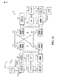
図1に示すように、1つの実施形態にしたがった多元接続無線通信システムが例示される。基地局100(BS)は、複数のアンテナ・グループを含んでおり、1つが104および106を含み、別のものが108および110を含み、さらに別のものが112および114を含んでいる。図1では、各アンテナ・グループについて2つのアンテナしか示されていないが、それより多くまたはそれより少ないアンテナが、おのおののアンテナ・グループのために利用されうる。ユーザ機器116(UE)は、アンテナ112およびアンテナ114と通信しており、アンテナ112およびアンテナ114は、ダウンリンク120によってUE116へ情報を送信し、アップリンク118によってUE116から情報を受信する。UE122はアンテナ106およびアンテナ108と通信しており、アンテナ106および108は、ダウンリンク126でUE122に情報を送信し、アップリンク124でUE122から情報を受信する。FDDシステムでは、通信リンク118、120、124、126は、通信のために異なる周波数を使用することができる。例えば、ダウンリンク120は、アップリンク118によって使用されるものとは異なる周波数を使用することができる。
(Pilot channel optimization)
As illustrated in FIG. 1, a multiple access wireless communication system according to one embodiment is illustrated. Base station 100 (BS) includes a plurality of antenna groups, one including 104 and 106, another including 108 and 110, and another including 112 and 114. In FIG. 1, only two antennas are shown for each antenna group, but more or fewer antennas may be utilized for each antenna group. User equipment 116 (UE) is in communication with
通信するように設計されたアンテナおよび/または領域の各グループはしばしば、基地局のセクタと称される。例示的な実施では、アンテナ・グループはおのおの、基地局100によってカバーされる領域のセクタ内のUEと通信するように設計される。
Each group of antennas and / or areas designed to communicate is often referred to as a base station sector. In the exemplary implementation, antenna groups are each designed to communicate with UEs in a sector of the area covered by
ダウンリンク120、126による通信では、基地局100の送信アンテナは、異なるUE116、124のためのダウンリンクの信号対雑音比を改善するために、ビームフォーミングを利用することができる。
For communication on the
上述するように、基地局は、端末との通信のために使用される固定局であることができ、また、アクセス・ポイント、ノードB、あるいはその他幾つかの用語で称されうる。ユーザ機器(UE)はまた、アクセス端末、無線通信デバイス、端末、あるいはその他幾つかの用語で称されうる。 As described above, a base station can be a fixed station used for communication with a terminal and can also be referred to as an access point, Node B, or some other terminology. User equipment (UE) may also be referred to as an access terminal, a wireless communication device, a terminal, or some other terminology.
図2は、本明細書に記載のシステムおよび方法の1または複数の局面と連携して利用される複数の基地局210および複数のユーザ機器(UE)220を備えた無線通信システム200を例示する。必ずしも必要ではないが、基地局は、一般に、端末と通信する固定局であり、アクセス・ポイント、ノードB、あるいはその他幾つかの用語で称されうる。おのおのの基地局210は、202a、202b、202cとラベルされた3つの地理的領域に例示するような特定の地理的領域のための通信有効範囲を提供する。用語「セル」は、その用語が使用される文脈に依存して、基地局および/またはその有効範囲領域を称することができる。システム容量を改善するために、基地局有効範囲は、(例えば、図2の有効範囲領域202aにしたがう3つの小さな領域)204a、204b、204cのような複数の小さな領域に分割されうる。おのおのの小さな領域は、それぞれ基地トランシーバ・サブシステム(BTS)によってサービス提供されうる。用語「セクタ」は、その用語が使用される文脈に依存して、BTSおよび/またはその有効範囲領域を称することができる。セクタ化されたセルの場合、そのセルのすべてのセクタのBTSは、一般に、そのセルの基地局内にともに配置される。本明細書に記載の送信技術は、セクタ化されていないセルを備えたシステムと同様、セクタ化されたセルを備えたシステムのためにも使用されうる。簡略化のために、以下の説明では、用語「基地局」は、セルにサービス提供する固定局のみならず、セクタにサービス提供する固定局に対しても総称的に使用される。
FIG. 2 illustrates a
ユーザ機器220は、一般に、システム中にわたって分散され、おのおののUEは据置式または移動式である。UEはまた、モバイル局、端末、ユーザ・デバイス、あるいはその他幾つかの用語で称されうる。UEは、無線デバイス、セルラ電話、携帯情報端末(PDA)、無線モデム・カード等でありうる。おのおのの端末220は、与えられた任意の時間において、ダウンリンクおよびアップリンクで、ゼロ、1、または複数の基地局と通信することができる。ダウンリンク(すなわち順方向リンク)は、基地局から端末への通信リンクを称し。アップリンク(すなわち逆方向リンク)は、端末から基地局への通信リンクを称する。
集中型アーキテクチャの場合、システム・コントローラ230は、基地局210へ連結されており、基地局210のための調整および制御を提供する。分散型アーキテクチャの場合、基地局210は、必要に応じて互いに通信することができる。ダウンリンクの追加チャネル(例えば、制御チャネル)は、複数の基地局から1つのUEへ送信されうる。アップリンク・データ通信は、図1に関連して上述したように、端末220または基地局210において、1または複数のアンテナを経由して、1つのUEから1または複数の基地局へ発生する。
In the case of a centralized architecture,
図3Aは、本明細書に記載のシステムおよび方法の様々な局面にしたがって、パイロット・チャネル最適化を容易にするシステムの典型的な限定しない高レベル・ブロック図を例示する。システム300Aは、基地局304と無線によって通信可能に接続されたユーザ機器304を含む。言い換えれば、基地局304は、ダウンリンク310でUE302に音声サービスおよび/またはデータ・サービスを提供しており、例えばCDMAまたは単一キャリア周波数分割多元接続(SC−FDMA)アップリンクのようなアップリンク312を介してユーザ機器302からの通信を受信している。ユーザ機器302は、本来、移動式であり、UE302が別の地理的領域に移ると、基地局304から受信する信号に関連する品質が変わる。ユーザ機器302は、パイロット・フィードバック・メカニズム306を含む。これは、他の機能のなかでもチャネル条件推定をイネーブルするために、本明細書で記述されたスキームにしたがってパイロット信号を効果的にモニタする基地局304に位置するパイロット制御メカニズム308によって提供される命令群に応答して、ユーザ機器の1または複数の電力制御動作を制御することに応答する。さらに、UE302および/または基地局304は、他の機能のなかでもとりわけ、パイロット割当スキームを適応して決定するために使用される関連情報またはデータの通信を容易にするその他の補助的な構成要素を含むことが認識されるべきである。
FIG. 3A illustrates an exemplary non-limiting high-level block diagram of a system that facilitates pilot channel optimization in accordance with various aspects of the systems and methods described herein.
図3Bは、本明細書で説明したシステムおよび方法の様々な局面にしたがってアップリンク・パイロット信号がモニタされるように、複数のUE302から信号を受信する基地局304を例示する。基地局304は、複数(1からZ、ただしZは整数)のUE302から信号を受信しているものとして示されている。
FIG. 3B illustrates a
以下の記述は、UMTSの文脈で、ネットワーク(例えば、基地局304および/またはシステム・コントローラ230)と無線端末(例えば、UE302またはUE220)との間のシグナリングに関するさらなる背景情報を提供する。局面では、論理チャネルが、制御チャネルおよびトラフィック・チャネルに分類される。論理制御チャネルは、システム制御情報をブロードキャストするためのダウンリンク(DL)チャネルであるブロードキャスト制御チャネル(BCCH)と、ページング情報を転送するダウンリンク・チャネルであるページング制御チャネル(PCCH)と、1または幾つかのマルチキャスト・トラフィック・チャネル(MTCH)のための制御情報と、マルチメディア・ブロードキャストおよびマルチキャスト・サービス(MBMS)とを送信するために使用されるポイント・トゥ・マルチポイント・ダウンリンク・チャネルであるマルチキャスト制御チャネル(MCCH)とを備える。一般に、ラジオ・リソース制御(RRC)接続を確立した後、このチャネルは、MBMSを受信するUE302によってのみ使用される。専用制御チャネル(DCCH)は、専用制御情報を送信するポイント・トゥ・ポイント双方向チャネルであり、RRC接続を有するUE302によって使用される。さらなる局面では、論理トラフィック・チャネルは、ポイント・トゥ・ポイント双方向チャネルでありユーザ情報の転送のために1つのUEに専用の専用トラフィック・チャネル(DTCH)を備える。また、トラフィック・データを送信するポイント・トゥ・マルチポイント・ダウンリンクのためのMTCHを備える。
The following description provides further background information regarding signaling between a network (eg,
さらなる局面では、輸送チャネルが、ダウンリンクとアップリンクに分類される。ダウンリンク輸送チャネルは、専用チャネル(DCH)、ブロードキャスト・チャネル(BCH)、フォワード・アクセス・チャネル(FACH)、高速ダウンリンク共有チャネル(HS−DSCH)、および、セル全体にブロードキャストされ、他の制御/トラフィック・チャネルのために使用されるPHYリソースへマップされたページング・チャネル(PCH)を備えるアップリンク輸送チャネルは、専用チャンネル(DCH)、エンハンスト専用チャンネル(E−DCH)、およびランダム・アクセス・チャネル(RACH)を備える。PHYチャネルは、DLチャネルおよびULチャネルからなるセットを備える。 In a further aspect, the transport channels are classified as downlink and uplink. Downlink transport channels are broadcast on dedicated channels (DCH), broadcast channels (BCH), forward access channels (FACH), high speed downlink shared channels (HS-DSCH), and other cells and other controls / Uplink transport channel with paging channel (PCH) mapped to PHY resources used for traffic channel is dedicated channel (DCH), enhanced dedicated channel (E-DCH), and random access A channel (RACH) is provided. The PHY channel comprises a set consisting of a DL channel and a UL channel.
本発明の特定の限定しない実施形態の記述のために、以下の名称が使用される。当業者であれば、開示した発明の精神から逸脱することなく様々な修正がなされうることを認識するだろう。したがって、本明細書の記載は、特許請求の範囲のスコープを維持しながら実現される多くの実施形態のうちのほんの1つであることが理解されるべきである。HS−DSCHは、高速ダウンリンク共有チャネルであり、CPICHは、共通パイロット・チャネルであり、スロットは、0.666ミリ秒(ms)の時間持続である。 The following names are used for the description of certain non-limiting embodiments of the invention. Those skilled in the art will recognize that various modifications can be made without departing from the spirit of the disclosed invention. Accordingly, it is to be understood that the description herein is only one of many implementations that can be implemented while maintaining the scope of the claims. The HS-DSCH is a high speed downlink shared channel, the CPICH is a common pilot channel, and the slot is 0.666 milliseconds (ms) in duration.
図4は、典型的な限定しないパイロット最適化の例示的な実施を示す。図示するように、無線通信システム400は、ユーザ機器402および基地局404を備える。これらは、通信チャネル412、410(例えば、パイロット・チャネル)を介してデータおよび動作信号を通信することができる。例示的な動作では、基地局パイロット制御メカニズム408は、ユーザ機器402においてパイロット・チャネル条件をモニタする。これによって、1または複数の電力条件信号(図示せず)が、1または複数の選択された条件(例えば、高データ・レート)にしたがってユーザ機器402のパイロット・チャネルの電力を制御する(例えば、パイロット・ブーストを実行する)ユーザ機器電力制御メカニズム406へ提供されうる。電力制御は、本明細書に記載された(すなわち、「パイロット・ブースト」セクションで記載されたような)例示される動作のうちの1または複数にしたがって実行されうる。
FIG. 4 illustrates an exemplary implementation of typical non-limiting pilot optimization. As illustrated, the
図5に示すように、無線通信環境内で適用される通信装置500が例示される。この装置500は、基地局304あるいはその一部、または、ユーザ機器302あるいはその一部(例えば、プロセッサに接続されたセキュア・デジタル(SD)カード)でありうる。装置500は、信号処理、通信のスケジューリング、測定ギャップの要求等に関する様々な命令群を保持するメモリ502を含みうる。例えば、装置500が、図11、12および15に関して以下に述べるようなユーザ機器である場合、メモリ502は、特定の基地局に関するアップリンク・チャネルおよび/またはダウンリンク・チャネルにおける信号の品質を分析するための命令群を含みうる。さらに、メモリ502は、パイロット・チャネル最適化のための命令群を備えることができる。その目的のために、メモリ502は、予め定められたスキームにしたがったパイロット・チャネル最適化を容易にするために、本明細書に記載のシステムおよび方法の様々な局面にしたがって、基地局304からアップリンク・パイロット・チャネル・データを受信し、それを処理するための命令群を備えうる。さらに、メモリ502は、最適化されたパイロット・チャネルの送信を容易にするための命令群を備えうる。上記命令群の例およびその他適切な命令群は、メモリ502内に保持されうる。そして、プロセッサ504は、(例えば、アクティブなストリームの数、周波数開始位置等に依存して)これら命令群を実行することに関連して利用されうる。
As shown in FIG. 5, a
また、上述したように、装置500は、図9、10および14に関連して以下に記載するような基地局および/またはその一部でありうる。一例として、メモリ502は、装置500によってサービス提供されているユーザ機器が、他の技術および/または周波数に関する測定を行っていることを示す表示を受信するための命令群を含みうる。メモリ502はさらに、本明細書に記載のシステムおよび方法の様々な局面にしたがって、予め定められたスキームにしたがって、UE302における1または複数の電力制御動作の実行を容易にするために、アップリンク・パイロット・チャネル・データを決定し、それを送信するための命令群を含みうる。その目的のために、メモリ502はさらに、最適化されたパイロット・チャネルの受信を容易にするための命令群を含みうる。プロセッサ504は、メモリ502内に保持された命令群を実行するために使用されうる。幾つかの例が提供されたが、(例えば、図6、7のような)方法論の形態で記述される命令群が、メモリ502内部に含まれ、プロセッサ504によって実行されることが理解される。
Also, as described above,
図6および図7に示すように、様々な例示的な実施にしたがってパイロット・チャネル電力条件を最適化するための特定の高レベルな方法論が例示される。説明を単純にするために、これら方法論は一連の動作として示され説明されているが、これら方法論は、この動作順に限定されず、幾つかの動作が、本明細書で示され説明されたものとは異なる順序でなされたり、および/または、他の動作と同時になされうることが理解され認識されるべきである。例えば、当業者であれば、方法論は、例えば状態図のような一連の相互関連する状態またはイベントとして表すこともできることを理解し認識するだろう。さらに、1または複数の実施形態にしたがって方法論を実施するために、必ずしも例示されたすべての動作が利用される訳ではない。 As shown in FIGS. 6 and 7, a particular high level methodology for optimizing pilot channel power conditions in accordance with various exemplary implementations is illustrated. For simplicity, these methodologies are shown and described as a series of operations, but these methodologies are not limited to this order of operation, and some operations are shown and described herein. It should be understood and appreciated that may be done in a different order and / or at the same time as other operations. For example, those skilled in the art will understand and appreciate that a methodology could also be represented as a series of interrelated states or events, such as a state diagram. Moreover, not all illustrated acts may be utilized to implement a methodology in accordance with one or more embodiments.
図6は、本明細書に記載されたパイロット最適化スキームに関するアップリンク・パイロット最適化を容易にする1つの特定の高レベルな方法論600を例示する。604では、パイロット・チャネルの電力の予め定められた関数にしたがって、パイロット最適化スキームを容易にするために、必要なアップリンク・チャネル情報が、基地局304またはその一部によって決定される。606では、1または複数のUE302からのそれぞれのアップリンク・パイロット・チャネル情報が、このパイロット・チャネル条件および/または状態に関連する予め定められた関数にしたがって、UE302パイロット最適化を容易にする。608では、UE302が、予め定められた機能およびそれぞれのアップリンク・パイロット・チャネル情報にしたがって、基地局304またはその一部からパイロット最適化コマンドを受信し、それを処理する。
FIG. 6 illustrates one particular high-
図7は、本明細書に記載されたパイロット最適化スキームに関してアップリンク・パイロット最適化を容易にするための1つの特定の高レベルな方法論700を例示する。704において、基地局304あるいはその一部からそれぞれのアップリンク・パイロット・チャネルを受信すると、UE302あるいはその一部は、706において、アップリンク・パイロット・チャネル情報の予め定めた関数にしたがって、パイロット・チャネルの電力を制御する。706では、UE302あるいはその一部は、電力制御されたパイロットを送信する。
FIG. 7 illustrates one particular high-
図8は、セルI 802およびセルM 804といった複数のセルを含む様々な局面にしたがって実現される通信システム800の一例を示す。近隣セル802、804は、セル境界領域868に示すように、僅かにオーバラップしており、おのおのが2つの隣接セル間で共有される近隣セル境界領域内にある基地局によって送信される信号間で信号干渉が生じる可能性があることに着目されたい。
FIG. 8 illustrates an example of a
セクタ境界領域は、近隣セクタにある基地局によって送信された信号間での信号干渉が生じる可能性がある。ライン816は、セクタI 810とセクタII 812との間のセクタ境界領域を表し、ライン818は、セクタII 812とセクタIII 814との間のセクタ境界領域を表し、ライン820は、セクタIII 814とセクタI 810との間のセクタ境界領域を表す。同様に、セルM 804は、第1のセクタであるセクタI 822、第2のセクタであるセクタII 824、および第3のセクタであるセクタIII 826を含んでいる。ライン828は、セクタI 822とセクタII 824との間のセクタ境界領域を表し、ライン830は、セクタII 824とセクタIIII 826との間のセクタ境界領域を表し、ライン832は、セクタIII 826とセクタI 822との間のセクタ境界領域を表す。セルI 802は、基地局(BS)である基地局I 806と、セクタ810、812、814のおのおのにおける複数のエンド・ノード(EN)(例えば、無線端末)を含んでいる。セクタI 810は、無線リンク840、842それぞれを介してBS806に接続されたEN(1)836とEN(X)838とを含む。セクタII 812は、無線リンク848、850それぞれを介してBS806に接続されたEN(1’)844とEN(X’)846とを含む。セクタIII 814は、無線リンク856、858それぞれを介してBS806に接続されたEN(1’’)852とEN(X’’)854とを含む。同様に、セルM 804は、基地局M 808と、セクタ822、824、826のおのおのにおける複数のエンド・ノード(EN)を含んでいる。セクタI 822は、無線リンク840’、842’それぞれを経由してBS M 808に接続されたEN(1)836’およびEN(X)838’を含む。セクタII 824は、無線リンク848’、850’それぞれを経由してBS M 808に接続されたEN(1’)844’、EN(X’)846’を含む。セクタIII 826は、無線リンク856’、858’それぞれを経由してBS 808に接続されたEN(1’’)852’、EN(X’’)854’を含む。
Sector boundary regions can cause signal interference between signals transmitted by base stations in neighboring sectors.
システム800はまた、ネットワーク・リンク862、864それぞれを経由してBS I 806およびBS M 808に接続されたネットワーク・ノード860を含む。ネットワーク・ノード860はまた、ネットワーク・リンク866を経由して、例えば他の基地局、AAAサーバ・ノード、中間ノード、ルータ等のようなその他のネットワーク・ノードおよびインターネットにも接続される。ネットワーク・リンク862、864、866は、例えば光ファイバ・ケーブルでありうる。例えばEN(1)836のような各エンド・ノードは、受信機のみならず送信機をも含む無線端末でありうる。例えばEN(1)836のような無線端末は、システム800中を移動することができ、無線リンクを経由して、ENが現在位置しているセル内の基地局と通信することができる。例えばEN(1)836のような無線端末は、例えばBS806のような基地局および/またはネットワーク・ノード860を経由して、例えばシステム800内あるいはシステム800外の他のWTのようなピア・ノードと通信することができる。例えば、EN(1)836のようなWTは、セル電話、無線モデムを備えた情報携帯端末等のようなモバイル通信デバイスでありうる。それぞれの基地局またはそれらの一部は、パイロット・アップリンク・チャネル情報の決定および送信を実行することができる。さらに、それぞれの基地局またはそれらの一部は、本明細書で提供された様々な局面にしたがってアップリンク・パイロット・デマルチプレクスを実行することができる。無線端末またはそれらの一部は、本明細書で提供された様々な局面にしたがった多くのアクティブ・ストリームの予め定められた関数にしたがって、一度にパイロット・チャネル帯域幅および周波数位置をSB402毎に変えることによってパイロットの適応的な多重化を容易にするために、提供されたそれぞれのアップリンク・パイロット・チャネル情報を用いうる。さらに、無線端末およびそれらの一部は、多重化されたパイロットをそれぞれの基地局へ送信することができる。
図9は、ユーザ機器に関する適応アップリンク・パイロット多重化スキームに関連して利用されるシステムを例示する。システム900は、1または複数の受信アンテナ906を経由して1または複数のユーザ・デバイス904から信号を受信し、複数の送信アンテナ908を介して1または複数のユーザ・デバイス904へ送る受信機910を備えうる。一例において、受信アンテナ906および送信アンテナ908は、1セットのアンテナを用いて実現されうる。受信機910は、受信アンテナ906から情報を受信し、受信した情報を復調する復調器912と動作可能に関連している。受信機910は、当業者によって認識されるように、例えば、レーキ受信機(例えば、複数のベースバンド相関を用いてマルチ・パス信号成分を個別に処理する技術、等)。MMSEベース受信機、あるいは、割り当てられたユーザ・デバイスを分けるその他幾つかの適切な受信機でありうる。例えば、(例えば、受信アンテナについて1つの)複数の受信機が適用され、そのような受信機が、互いに通信して、改善されたユーザ・データ推定値を提供する。復調されたシンボルは、図11に関して後述するようなプロセッサ1106に類似しメモリ916に接続されたプロセッサ914によって分析される。メモリ916は、ユーザ・デバイス割当、関連するルックアップ・テーブル等に関する情報を格納する。おのおののアンテナの受信機出力は、受信機910および/またはプロセッサ914によって共同して処理されうる。変調器918は、送信アンテナ908を介して送信機920によってユーザ・デバイス904へ送信される信号を多重化する。
FIG. 9 illustrates a system utilized in connection with an adaptive uplink pilot multiplexing scheme for user equipment.
図10は、本発明の様々な局面にしたがった基地局1000の一例を例示する。基地局1000あるいはそれらの一部は、本明細書に記載のシステムおよび方法の様々な局面を実施する。例えば、基地局1000は、関連するユーザ機器において、適応パイロット多重化を容易にするために、次の送信のためのパイロット・アップリンク・チャネル情報を決定することができる。基地局1000は、図8のシステム800の基地局806、808のうちの任意の1つとして使用されうる。基地局1000は、様々な要素1002、1004、1006、1008、1010がデータおよび情報を交換するバス1009に共に接続された受信機1002、送信機1004、例えばCPUのようなプロセッサ1006、入力/出力インタフェース1008、メモリ1010を含む。
FIG. 10 illustrates an
1または複数の受信アンテナを備えうる受信機1002に接続されたセクタ化アンテナ1003は、基地局のセル内のおのおののセクタからの無線端末送信から、データや例えばチャネル・レポートのようなその他の信号を受信するために使用される。送信機1004に接続されたセクタ化アンテナ1005は、基地局のセルのおのおののセクタ内の無線端末1200(図12参照)へ、データおよび例えば制御信号、パイロット信号、ビーコン信号等のようなその他の信号を送信するために使用される。様々な局面において、基地局1000は、例えばおのおののセクタ用の個々の受信機1002、およびおのおののセクタ用の個々の送信機1004のように、複数の受信機1002と複数の送信機1004とを用いる。上述したように、様々な変形が可能であることが認識されるべきである。例えば、SU−MIMOシステムでは、基地局およびユーザ機器において、複数の送信アンテナおよび受信アンテナ等が使用されうる。同様に、SDMAシステムの場合、複数のユーザが、複数の送信アンテナ、受信アンテナ、および受信機を有する基地局からの信号を送受信することができる。プロセッサ1006は、例えば汎用中央処理装置(CPU)でありうる。プロセッサ1006は、メモリ1010に格納された1または複数のルーチン1018の指示の下、基地局1000の動作を制御し、方法を実施する。I/Oインタフェース1008は、他のネットワーク・ノードへの接続を提供し、BS1000を他の基地局、アクセス・ルータ、AAAサーバ・ノード等や、他のネットワーク、およびインターネットへ接続する。メモリ1010は、ルーチン1018およびデータ/情報1020を含む。
A
データ/情報1020は、データ1036、ダウンリンク・ストリップ・シンボル時間情報1040とダウンリンク・トーン情報1042とを含むトーン・サブセット割当シーケンス情報1038、WT 1情報1046およびWT N情報1060からなるWT情報の複数のセットを含む無線端末(WT)データ/情報1044を含む。例えばWT 1情報1046のようなWT情報のおのおののセットは、データ1048、端末ID1050、セクタID1052、アップリンク・チャネル情報1054、ダウンリンク・チャネル情報1056、およびモード情報1058を含む。
Data /
ルーチン1018は、通信ルーチン1022および基地局制御ルーチン1024を含む。基地局制御ルーチン1024は、ストリップ・シンボル期間のためのトーン・サブセット割当ルーチン1030、残りのシンボル期間のためのその他のダウンリンク・トーン割当ホッピング・ルーチン1032、およびビーコン・ルーチン1034を含むシグナリング・ルーチン1028と、スケジューラ・モジュール1026とを含む。
データ1036は、WTへの送信前の符号化のために送信機1004のエンコーダ1014へ送られる送信用データと、受信にしたがって受信機1002のデコーダ1012によって処理されたWTからの受信データとを含む。ダウンリンク・ストリップ・シンボル時間情報1040は、例えばスーパスロット構造情報、ビーコンスロット構造情報、およびウルトラ・スロット構造情報のようなフレーム同期構造情報と、与えられたシンボル期間がストリップ・シンボル期間であるかを指定し、もしもそうであれば、ストリップ・シンボル期間のインデクスであり、さらに、このストリップ・シンボルが基地局によって使用されるトーン・サブセット割当シーケンスを切り詰めるリセット・ポイントであるかを指定する情報とを含む。ダウンリンク・トーン情報1042は、基地局1000に割り当てられたキャリア周波数と、トーンの数および周波数と、ストリップ・シンボル期間に割り当てられるトーン・サブセットのセットと、例えばスロープ、スロープ・インデクス、およびセクタ・タイプのようにその他のセルおよびセクタに特有の値とを含む。
Data 1036 includes data for transmission sent to
データ1048は、WT1 1200がピア・ノードから受信したデータ、WT1 1200がピア・ノードへ送信されることを望むデータ、および、チャネル品質レポート・フィードバック情報を含む。端末ID 1050は、基地局1000に割り当てられたIDであり、WT1 1200を識別する。セクタID 1052は、WT1 1200が動作しているセクタを識別する情報を含む。セクタID 1052は、例えば、セクタ・タイプを判定するために使用されうる。アップリンク・チャネル情報1054は、例えば、データのためのアップリンク・トラフィック・チャネル・セグメント、要求のための専用アップリンク制御チャネル、電力制御、タイミング制御、アクティブ・ストリームの数等のように、WT1 1200が使用するためにスケジューラ1026によって割り当てられたチャネル・セグメントを識別する情報を含む。WT1 1200に割り当てられたおのおののアップリンク・チャネルは、1または複数の論理トーンを含む。おのおのの論理トーンは、本発明の様々な局面にしたがうアップリンク・ホッピング・シーケンスにしたがう。ダウンリンク・チャネル情報1056は、例えばユーザ・データのためのダウンリンク・トラフィック制御セグメントのようなデータおよび/または情報をWT1 1200へ搬送するために、スケジューラ1026によって割り当てられたチャネル・セグメントを識別する情報を含む。WT1 1200に割り当てられたおのおののダウンリンク・チャネルは、おのおのダウンリンク・ホッピング・シーケンスにしたがう1または複数の論理トーンを含む。モード情報1058は、例えばスリープ、ホールド、オン等のようなWT1 1200の動作状態を識別する情報を含む。
通信ルーチン1022は、様々な通信動作の実行、および様々な通信プロトコルの実施を行う基地局1000を制御する。基地局制御ルーチン1024は、例えば信号生成、受信、およびスケジューリングのような基本的な基地局機能タスクの実行、および、ストリップ・シンボル期間中にトーン・サブセット割当シーケンスを用いて信号を無線端末へ送信することを含む幾つかの局面の方法ステップの実施を行う基地局1000を制御するために使用される。
The communication routine 1022 controls the
シグナリング・ルーチン1028は、デコーダ1012を備えた受信機1002、および、エンコーダ1014を備えた送信機1004の動作を制御する。シグナリング・ルーチン1028は、送信されるデータ1036および制御情報の生成を制御することを担当する。トーン・サブセット割当ルーチン1030は、本局面の方法を用いて、および、ダウンリンク・ストリップ・シンボル時間情報1040およびセクタID1052を含むデータ/情報1020を用いて、ストリップ・シンボル期間において使用されるトーン・サブセットを構築する。ダウンリンク・トーン・サブセット割当シーケンスは、セル内のおのおののセクタ・タイプで、および、隣接セルで異なるであろう。WT1200は、ダウンリンク・トーン・サブセット割当シーケンスにしたがって、ストリップ・シンボル期間において信号を受信し、基地局1000は、送信される信号を生成するために、同一のダウンリンク・トーン・サブセット割当シーケンスを用いる。その他のダウンリンク・トーン割当ホッピング・ルーチン1032は、ストリップ・シンボル期間以外のシンボル期間のために、ダウンリンク・トーン情報1042およびダウンリンク・チャネル情報1056を含む情報を用いて、ダウンリンク・トーン・ホッピング・シーケンスを構築する。ダウンリンク・データ・トーン・ホッピング・シーケンスは、セルのセクタにわたって同期化される。ビーコン・ルーチン1034は、例えばダウンリンク信号のフレーム・タイミング構造を同期化するために、例えば、1または少数のトーンに集中された比較的高い電力信号のシグナルのように、同期化目的のために使用されるビーコン信号の送信、つまり、ウルトラ・スロット境界に関するトーン・サブセット割当シーケンスを制御する。
Signaling routine 1028 controls the operation of
図11は、本明細書に記載されるようなパイロット最適化スキームに関連して利用されうるシステム1100を例示する。システム1100は、例えば1または複数の受信アンテナからの信号の受信、受信した信号に対する一般的な動作(例えば、フィルタ、増幅、ダウンコンバート等)、これら調整された信号のデジタル化、ならびに、サンプルの取得を行う受信機1102を備える。パイロット制御メカニズム1104は、チャネル推定のために、受信したパイロット・シンボルをプロセッサ1106へ提供する。
FIG. 11 illustrates a
プロセッサ1106は、受信機構成要素1102によって受信された情報の分析、および/または、送信機1114による送信のための情報の生成に特化されたプロセッサでありうる。プロセッサ1106は、システム1100の1または複数の部分を制御するプロセッサ、および/または、受信機1102によって受信された情報の分析、送信機1114によって送信される情報の生成、システム1100のうちの1または複数の部分の制御を行うプロセッサでありうる。システム1100は、1または複数の技術および/または周波数に関する測定の実行前、実行中、および/または実行後に、ユーザ機器のパフォーマンスを最適化することができる。最適化構成要素1108は、プロセッサ1106に組み込まれうる。最適化構成要素1108は、要求する測定ギャップに関連してユーティリィ・ベースの分析を実行する最適化コードを含みうることが認識されるべきである。この最適化コードは、推論実行に関連する人工知能ベースの方法、および/または、スキームの符号化および復号に関連する確率論的判定および/または統計ベースの判定を利用しうる。
The
システム(ユーザ機器)1100はさらに、動作可能にプロセッサ1106に接続され例えば測定ギャップ情報、スケジューリング情報等のような情報を格納するメモリ1110を備えうる。これらの情報は、要求する測定ギャップを割り当てることと、測定ギャップ中に測定を実行することとに関連して適用されうる。メモリ1110はさらに、ルックアップ・テーブル等を生成することに関連するプロトコルを格納し、これによって、システム1100は、システム容量を高めるために、格納されたプロトコルおよび/またはアルゴリズムを適用することができる。本明細書に記載されたデータ・ストア(例えば、メモリ)構成要素は、揮発性メモリまたは不揮発性メモリの何れかであるか、あるいは、揮発性メモリと不揮発性メモリとの両方でありうることが認識されるだろう。限定ではなく例示によって、不揮発性メモリは、読取専用メモリ(ROM)、プログラマブルROM(PROM)、電子的プロラマブルROM(EPROM)、電子的消去可能ROM(EEPROM)、またはフラッシュ・メモリを含みうる。揮発性メモリは、外部キャッシュ・メモリとして動作するランダム・アクセス・メモリ(RAM)を含みうる。限定ではなく例示によって、RAMは、例えばシンクロナスRAM(SRAM)、ダイナミックRAM(DRAM)、シンクロナスDRAM(SDRAM)、ダブル・データ・レートSDRAM(DDR SDRAM)、エンハンストSDRAM(ESDRAM)、シンクリンクDRAM(SLDRAM)、およびダイレクト・ラムバスRAM(DRRAM(登録商標))のような多くの形態で利用可能である。メモリ1110は、限定される訳ではないが、これらのタイプのメモリ、あるいはその他任意の適切なタイプのメモリを備えることが意図される。プロセッサ1106は、シンボル・パイロット・フィードバック・メカニズム1112と、変調された信号を送信する送信機1114とに接続される。
The system (user equipment) 1100 may further comprise a
図12は、無線端末(例えば、図8のシステム800のEN(1)836)のうちの任意の1つとして使用されうる典型的な無線端末(例えば、エンド・ノード、モバイル・デバイス等)1200を例示する。無線端末1200は、様々な要素1202、1204、1206、1208がデータおよび情報を交換することができるバス1210によって共に接続された、デコーダ1212を含む受信機1202と、エンコーダ1214を含む送信機1204と、プロセッサ1206と、メモリ1208とを含む。基地局からの信号を受信するために使用されるアンテナ1203が、受信機1202に接続される。例えば基地局へ信号を送信するために使用されるアンテナ1205が、送信機1204に接続される。上述したように、様々な変形が可能であることが認識されるべきである。例えば、SU−MIMOシステムでは、基地局およびユーザ機器において、複数の送信アンテナおよび受信アンテナが使用されうる。同様に、SDMAシステムの場合、複数のユーザが、複数の送信アンテナおよび受信アンテナを有する基地局から信号を送信および受信等することができる。
12 illustrates an exemplary wireless terminal (eg, end node, mobile device, etc.) 1200 that may be used as any one of the wireless terminals (eg, EN (1) 836 of the
例えばCPUのようなプロセッサ1206が無線端末1200の動作を制御する。そして、メモリ1208内のルーチン1220を実行し、データ/情報1222を用いることによって方法を実施する。
For example, a
データ/情報1222は、OFDMA通信システムの例の場合、ユーザ・データ1234、ユーザ情報1236、およびトーン・サブセット割当シーケンス情報1250を含む。ユーザ・データ1234は、送信機1204によって基地局100へ送信される前に符号化されるためにエンコーダ1214へと送られる、ピア・ノードに向けられたデータと、基地局1000から送られ受信機1202内のデコーダ1212によって処理されたデータとを含みうる。ユーザ情報1236は、アップリンク・チャネル情報1238、ダウンリンク・チャネル情報1240、端末ID情報1242、基地局ID情報1244、セクタID情報1246、およびモード情報1248を含む。アップリンク・チャネル情報1238は、無線端末1200が基地局1000へ送信する場合に利用するために、基地局1000によって割り当てられたアップリンク・チャネル・セグメントを識別する情報を含む。アップリンク・チャネルは、アップリンク・トラフィック・チャネルや、例えば要求チャネル、電力制御チャネル、およびタイミング制御チャネルのような専用アップリンク制御チャネルを含みうる。OFDMA通信システムの典型的な場合では、おのおののアップリンク・チャネルは、1または複数の論理トーンを含む。おのおのの論理トーンは、アップリンク・トーン・ホッピング・シーケンスにしたがう。幾つかの実施形態では、アップリンク・ホッピング・シーケンスは、セルの各セクタ・タイプで、および、隣接セル間で異なる。
Data /
ダウンリンク・チャネル情報1240は、基地局がデータ/情報をWT1200へ送信しているとき、WT1200が使用するために基地局によって割り当てられたダウンリンク・チャネル・セグメントを識別する情報を含む。ダウンリンク・チャネルは、ダウンリンク・トラフィック・チャネルおよび割当チャネルを含む。これらはおのおの1または複数の論理トーンを含み、おのおのの論理トーンは、セルの各セクタの間で同期化されるダウンリンク・ホッピング・シーケンスにしたがう。
Downlink channel information 1240 includes information identifying downlink channel segments allocated by the base station for use by the
ユーザ情報1236はまた、基地局1000が割り当てた識別情報である端末ID情報1242と、WTが通信を確立した特定の基地局1000を識別する基地局ID情報1244と、WT1200が現在位置しているセルの特定のセクタを識別するセクタID情報1246とを含む。OFDMA通信システムの例では、基地局ID1244が、セル・スロープ値を提供し、セクタID情報1246が、セクタ・インデクス・タイプを提供し、セル・スロープ値およびセクタ・インデクス・タイプが、トーン・ホッピング・シーケンスを導出するために使用される。ユーザ情報1236には、WT1200がスリープ・モードであるか、ホールド・モードであるか、あるいはオン・モードであるかを識別するモード情報1248が含まれる。
The
幾つかのOFDMA実施形態では、トーン・サブセット割当シーケンス情報1250が、ダウンリンク・ストリップ・シンボル時間情報1252と、ダウンリンク・トーン情報1254とを含む。ダウンリンク・トーン情報1254は、基地局1000に割り当てられたキャリア周波数を含む情報と、トーンの周波数および数、ストリップ・シンボル期間に割り当てられるべきトーン・サブセットのセットの数、および他のセルの数と、例えばスロープ、スロープ・インデクス、およびセクタ・タイプのようなセクタ特有の値とを含む。
In some OFDMA embodiments, tone subset assignment sequence information 1250 includes downlink strip symbol time information 1252 and
ルーチン1220は、通信ルーチン1224および無線端末制御ルーチン1226を含む。通信ルーチン1224は、WT1200によって使用される様々な通信プロトコルを制御する。無線端末制御ルーチン1226は、受信機1202および送信機1204の制御を含む基本的無線端末1200の機能を制御する。無線端末制御ルーチン1226は、シグナリング・ルーチン1228を含む。幾つかのOFDMA実施形態では、トーン・サブセット割当ルーチン1230は、幾つかの実施形態にしたがってダウンリンク・トーン・サブセット割当シーケンスを生成し、かつ、基地局1000から送信された受信データを処理するために、ダウンリンク・チャネル情報1240、例えばスロープ・インデクスおよびセクタ・タイプのような基地局ID情報1244、および、ダウンリンク・トーン情報1254を含むユーザ・データ/情報1222を使用する。
The routine 1220 includes a communication routine 1224 and a wireless
幾つかの例示的な実施の技術は、ソフトウェア、ハードウェア、および/または、ソフトウェアとハードウェアとの組み合わせを用いて実施されうる。幾つかの実施形態は、例えばモバイル端末、基地局、または、幾つかの例示的な実装を実現する通信システムのようなモバイル・ノードである装置に向けられる。幾つかの例示的な実施はまた、幾つかの例示的な実施にしたがって、例えばホストのような通信システム、基地局、および/またはモバイル・ノードの制御および/または操作を行う方法のような方法に向けられる。幾つかの例示的な実施はまた、幾つかの例示的な実施にしたがって1または複数のステップを実施する機械を制御するための機械読取可能な命令群を含む例えばROM、RAM、CD、ハード・ディスク等のような機械読取可能媒体にも向けられる。 Some example implementation techniques may be implemented using software, hardware, and / or a combination of software and hardware. Some embodiments are directed to devices that are mobile nodes, such as mobile terminals, base stations, or communication systems that implement some example implementations. Some exemplary implementations also include methods, such as methods for controlling and / or operating a communication system, base station, and / or mobile node, eg, a host, according to some exemplary implementations. Directed to. Some example implementations also include machine readable instructions for controlling a machine that performs one or more steps according to some example implementations, such as ROM, RAM, CD, hardware, etc. It is also directed to machine-readable media such as disks.
本明細書に記載された例示的な様々なノードは、例えば信号処理、メッセージ生成および/または送信のような幾つかの例示的な実施からなる1または複数の方法に対応するステップを実行する1または複数のモジュールを用いて実現される。したがって、幾つかの例示的な実施では、幾つかの例示的な実施の様々な特徴が、モジュールを用いて実現される。そのようなモジュールは、ソフトウェア、ハードウェア、あるいはソフトウェアとハードウェアとの組み合わせを使用して実現することができる。上述された方法または方法ステップの多くは、例えば1または複数のノードのような上述したノードのすべてまたは一部を実現する追加ハードウェアを備えたあるいは備えていない汎用コンピュータのような機械を制御するために、例えばRAM、フロッピー(登録商標)ディスク等のメモリ・デバイスのような機械読取可能媒体に含まれた例えばソフトウェアのような機械実行可能命令群を用いて実現されうる。したがって、幾つかの実施形態は、例えばプロセッサや関連ハードウェアのような機械に対して、上述した方法のステップのうちの1または複数を実行させる機械読取可能命令群を含む機械読取可能媒体に向けられる。 Various exemplary nodes described herein perform steps corresponding to one or more methods consisting of several exemplary implementations, such as signal processing, message generation and / or transmission, for example. Alternatively, it is realized using a plurality of modules. Thus, in some exemplary implementations, various features of some exemplary implementations are implemented using modules. Such a module can be implemented using software, hardware, or a combination of software and hardware. Many of the methods or method steps described above control a machine, such as a general purpose computer, with or without additional hardware that implements all or part of the nodes described above, such as one or more nodes. Thus, it can be implemented using machine-executable instructions such as software included in a machine-readable medium such as a memory device such as a RAM or a floppy disk. Accordingly, some embodiments are directed to a machine readable medium including machine readable instructions that cause a machine, such as a processor or associated hardware, to perform one or more of the method steps described above. It is done.
上述した例示的な実施からなる方法および装置に関する多くのさらなるバリエーションが、幾つかの例示的な実施の記述を参照して、当業者に明らかになるであろう。そのようなバリエーションは、それぞれの例示的な実施のスコープ内にあると考えられるべきである。幾つかの例示的な実施、および幾つかの実施形態における方法および装置は、CDMA、直交周波数分割多重化(OFDM)、SC−FDMA、および/または、アクセス・ノードとモバイル・ノードとの間の無線通信リンクを提供するために使用されるその他の様々なタイプの通信技術と共に使用されうる。幾つかの例示的な実施では、アクセス・ノードは、OFDMおよび/またはCDMAを用いてモバイル・ノードと通信リンクを確立する基地局として実現される。様々な実施形態では、モバイル・ノードは、ノートブック・コンピュータ、情報携帯端末(PDA)、あるいは、これら幾つかの実施形態の方法を実現するための受信機回路/送信機回路およびロジックおよび/またはルーチンを含むその他のポータブル・デバイスとして実現されうる。 Many further variations on the methods and apparatus comprising the exemplary implementations described above will be apparent to those skilled in the art with reference to several exemplary implementation descriptions. Such variations are to be considered within the scope of each exemplary implementation. Some example implementations, and methods and apparatus in some embodiments, include CDMA, orthogonal frequency division multiplexing (OFDM), SC-FDMA, and / or between an access node and a mobile node. It can be used with various other types of communication technologies used to provide a wireless communication link. In some exemplary implementations, the access node is implemented as a base station that establishes a communication link with the mobile node using OFDM and / or CDMA. In various embodiments, the mobile node may be a notebook computer, a personal digital assistant (PDA), or receiver / transmitter circuitry and logic and / or logic for implementing the methods of some embodiments. It can be implemented as other portable devices including routines.
本明細書に記載の1または複数の局面にしたがって、アップリンク・パイロット・チャネル情報を決定することに関する推論がなされることが認識されるだろう。本明細書で使用されるように、「推論する」または「推論」なる用語は一般に、イベントおよび/またはデータを介して取得された観察のセットから、システム、環境および/またはユーザ、モバイル・デバイス、アクティブ・アップリンク・ストリーム、および基地局の状態を推論するか、あるいはそれに関する理由付けをする処理を称する。推論は、特定の文脈または動作を識別するために使用することができるか、あるいは、例えば、状態にわたった確率分布を生成することができる。推論は、確率論的である。すなわち、データおよびイベントの考慮に基づく当該状態にわたる確率分布の計算である。推論はまた、イベントおよび/またはデータのセットから、より高レベルのイベントを構成するために適用される技術をも称する。そのような推論の結果、これらイベントが時間的に近接して相関してようといまいと、これらイベントおよびデータが、1または幾つかのイベント・ソースおよびデータ・ソースから由来していようといまいと、観察されたイベントおよび/または格納されたイベント・データのセットから、新たなイベントまたはアクションを構築することができる。 It will be appreciated that inferences regarding determining uplink pilot channel information can be made in accordance with one or more aspects set forth herein. As used herein, the term “infer” or “inference” generally refers to a system, environment and / or user, mobile device from a set of observations obtained through events and / or data. , Active uplink stream, and the process of inferring or reasoning about the state of the base station. Inference can be employed to identify a specific context or action, or can generate a probability distribution over states, for example. Inference is probabilistic. That is, the calculation of the probability distribution over the state based on data and event considerations. Inference also refers to techniques applied to construct higher level events from a set of events and / or data. As a result of such inference, whether these events are closely related in time or whether these events and data are from one or several event sources and data sources New events or actions can be constructed from the observed events and / or the stored set of event data.
例によれば、上述した1または複数の方法は、適応性のあるアップリンク・パイロット多重化を容易にするアクティブなアップリンク・ストリームを決定することに関する推論を行うことを含む。別の例によれば、推論は、アップリンク・パイロット信号のセットに基づいて、1または複数の望まれない信号から弁別可能な所望の信号の確率を推定することに関連してなされる。前述した例は本質的に例示的であり、なされうる推論の数、あるいは、そのような推論が本明細書に記載の様々な実施形態および/または方法に関連してなされる方法に限定されることは意図されていないことが認識されるだろう。 According to an example, the one or more methods described above include making inferences about determining an active uplink stream that facilitates adaptive uplink pilot multiplexing. According to another example, inference is made in connection with estimating a probability of a desired signal that can be distinguished from one or more unwanted signals based on a set of uplink pilot signals. The foregoing examples are exemplary in nature and are limited to the number of inferences that can be made, or the methods by which such inferences are made in connection with the various embodiments and / or methods described herein. It will be recognized that this is not intended.
図13は、本発明の様々な局面にしたがったパイロット最適化を組み込んだ通信システムの限定しない典型的なブロック図を例示しており、MIMOシステム1300における送信機システム1310(例えば、基地局、基地局等)と受信機システム1350(UE、ユーザ機器、モバイル・ノード)がある。送信機システム1310では、多くのデータ・ストリームのためのトラフィック・データが、データ・ソース1312から送信(TX)データ・プロセッサ1314へ提供される。例示的な実施では、おのおののデータ・ストリームが、それぞれの送信アンテナを介して送信される。TXデータ・プロセッサ1314は、符号化されたデータを提供するために、そのデータ・ストリームのために選択された特定の符号化スキームに基づいて、おのおののデータ・ストリームのためのトラフィック・データをフォーマットし、符号化し、インタリーブする。本明細書に記述されたシステムおよび方法の例示的な様々な実施にしたがって、送信機システム1310は、受信機システム1350にアップリンク・パイロット・チャネル情報を送信することによって、パイロット最適化スキームを容易にする。
FIG. 13 illustrates a non-limiting exemplary block diagram of a communication system incorporating pilot optimization in accordance with various aspects of the present invention, such as transmitter system 1310 (eg, base station, base station) in
おのおののデータ・ストリームのための符号化されたデータは、OFDM技術を用いて、パイロット・データと多重化されうる。パイロット・データは、一般に、既知の方法で処理された既知のデータ・パターンであり、受信機システムにおいて、チャネル応答を推定するために使用されうる。おのおののデータ・ストリームのデータ・レート、符号化、および変調は、プロセッサ1330によって実行される命令群によって決定されうる。
The encoded data for each data stream can be multiplexed with pilot data using OFDM techniques. The pilot data is typically a known data pattern that is processed in a known manner and can be used at the receiver system to estimate the channel response. The data rate, coding, and modulation for each data stream can be determined by instructions executed by
すべてのデータ・ストリームのための変調シンボルは、その後、TXプロセッサ1320へ提供される。TXプロセッサ1320はさらに、(例えば、OFDMのために)この変調シンボルを処理する。TXプロセッサ1320はその後、NT個の変調シンボル・ストリームを、NT個の送信機(TMTR)1322a乃至1322tへ提供する。ある実施形態では、TXプロセッサ1320は、ビームフォーミング重みを、データ・ストリームのシンボル、および、このシンボルが送信されるアンテナへ適用する。
The modulation symbols for all data streams are then provided to
おのおのの送信機1322は、シンボル・ストリームをそれぞれ受信して処理し、1または複数のアナログ信号を提供する。そして、さらに、このアナログ信号を調整(例えば、増幅、フィルタ、およびアップコンバート)し、MIMOチャネルを介した送信に適した変調信号を提供する。その後、送信機1322a乃至1322tからNT個の変調信号が、NT個のアンテナ1324a乃至1324tからそれぞれ送信される。
Each transmitter 1322 receives and processes a respective symbol stream and provides one or more analog signals. The analog signal is then adjusted (eg, amplified, filtered, and upconverted) to provide a modulated signal suitable for transmission over the MIMO channel. Thereafter, the N T modulated signals from transmitters 1322a through 1322t are transmitted from N T
受信機システム1350では、この送信された変調信号がNR個のアンテナ1352a乃至1352rによって受信され、おのおののアンテナ1352からの受信信号が、それぞれの受信機(RCVR)1354a乃至1354rへ提供される。おのおのの受信機1354は、それぞれの受信信号を調整(例えば、フィルタ、増幅、およびダウンコンバート)し、調整した信号をデジタル化して、サンプルを提供する。そしてさらに、このサンプルを処理して、対応する「受信された」シンボル・ストリームを提供する。
At
その後、RXデータ・プロセッサ1360が、NR個の受信機1354からNR個の受信されたシンボル・ストリームを受け取り、特定の受信機処理技術に基づいて処理し、NT個の「検出された」シンボル・ストリームを提供する。RXデータ・プロセッサ1360は、その後、検出されたシンボル・ストリームのおのおのを復調、デインタリーブ、および復号して、そのデータ・ストリームのためのトラフィック・データを復元する。RXデータ・プロセッサ1360による処理は、送信機システム1310のTX MIMOプロセッサ1320およびTXデータ・プロセッサ1314によって行なわれる処理と相補的である。
Then,
プロセッサ1370は、上述したようにして、どの事前符号化行列を用いるべきかを定期的に決定する。プロセッサ1370は、行列インデクス部とランク値部とを備える逆方向リンク・メッセージを規定する。逆方向リンク・メッセージは、通信リンクおよび/または受信されたデータ・ストリームに関する様々なタイプの情報を備える。本発明の様々な局面によれば、送信機システム1310からアップリンク・パイロット・チャネル情報をそれぞれ受信することに応答して、受信機システム1350は、予め定めた機能にしたがってパイロット・チャネルを最適化する。逆方向リンク・メッセージはその後、多くのデータ・ストリームのトラフィック・データをデータ・ソース1336から受信するTXデータ・プロセッサ1338によって処理され、変調器1380によって変調され、送信機1354a乃至1354rによって調整され、送信機システム1310へ送り戻される。
The
送信機システム1310では、受信機システム1350からの変調信号が、アンテナ1324によって受信され、受信機1322によって調整され、復調器1340によって復調され、RXデータ・プロセッサ1342によって処理されて、受信機システム1350によって送信された逆方向リンク・メッセージが抽出される。その後、プロセッサ1330が、ビームフォーミング重みを決定するためにどの事前符号化行列を用いるのかを決定し、その後、この抽出されたメッセージを処理する。本発明の様々な局面によれば、受信機システム1350からの多重化パイロットを受信することに応答して、送信機システム1310は、予め定めた機能およびそれぞれのアップリンク・パイロット・チャネル情報にしたがって、この多重化パイロット・チャネルをデマルチプレクスする。
At
図14に示すように、本明細書に記載のシステムおよび方法の限定しない様々な例示的実施にしたがって、パイロット最適化を容易にする装置1400が例示される。例えば、装置1400は、基地局内に少なくとも部分的に存在しうる。装置1400は、プロセッサ、ソフトウェア、または(例えばファームウェアのような)これらの組み合わせによって実現される機能を表す機能ブロックでありうる機能ブロックを含むものとして表されることが認識されるべきである。装置1400は、連携して動作する電子構成要素の論理グループ1402を含む。例えば、論理グループ1402は、アップリンク・パイロット・チャネル情報の決定および送信のための基地局における電子構成要素1404を含む。例示であり限定しない目的で、アップリンク・パイロット・チャネル情報は、多重化される1または複数のアクティブ・ストリームの数、利用可能なリソース・ブロックの数、および/または、パイロット開始周波数位置、これらの任意の組み合わせ等を含みうる。さらに、論理グループ1402は、図4、6−7に関連して既により詳細に説明したように、パイロット制御を表す信号を受信する電子構成要素1406を含みうる。論理グループ1402はさらに、アップリンク・パイロット・チャネル情報の予め定めた関数にしたがって、パイロット制御信号を処理する電子構成要素1408を含みうる。さらに、装置1400は、電子構成要素1404、1406、1408に関連する機能を実行するための命令群を保持するメモリ1410を含みうる。メモリ1410の外側にあるように示されているが、電子構成要素1404、1406、1408のうちの1または複数は、メモリ1410内に存在しうることが理解されるべきである。
With reference to FIG. 14, illustrated is an apparatus 1400 that facilitates pilot optimization in accordance with various non-limiting exemplary implementations of the systems and methods described herein. For example, apparatus 1400 can reside at least partially within a base station. It should be appreciated that apparatus 1400 is represented as including functional blocks, which can be functional blocks representing functions implemented by a processor, software, or combination thereof (eg, firmware). Apparatus 1400 includes a
図15に示すように、本明細書に記載のシステムおよび方法の限定しない様々な例示的実施にしたがってパイロット最適化をイネーブルする装置1500が例示される。装置1500は、例えば、無線端末内に少なくとも部分的に存在することができる。装置1500は、プロセッサ、ソフトウェア、または(例えばファームウェアのような)これらの組み合わせによって実現される機能を表す機能ブロックでありうる機能ブロックを含むものとして表されることが認識されるべきである。装置1500は、連携して動作しうる電子構成要素の論理グループ1502を含む。例えば、論理グループ1502は、アップリンク・パイロット・チャネル情報を受信し処理する電子構成要素1504を含みうる。例えば、電子構成要素1504は、図14に関して上述したように、アップリンク・パイロット・チャネルを受信して処理する電子構成要素を含みうる。さらに、論理グループ1502は、図4、6−7に関連して既に詳細に説明したように、アップリンク・パイロット・チャネル情報に基づいてパイロット制御データを処理する電子構成要素1506を含みうる。さらに、論理グループ1502は、パイロット・フィードバック・データを送信する電子構成要素1508を含みうる。さらに、装置1500は、電子構成要素1504、1506、1508に関連する機能を実行するための命令群を保持するメモリ1510を含むことができる。メモリ1510の外側にあるとして示されているが、電子構成要素1504、1506、1508の1または複数は、メモリ1510内に存在することができると理解されるべきである。
With reference to FIG. 15, illustrated is an
本明細書で説明された例示的な実施は、ハードウェア、ソフトウェア、ファームウェア、ミドルウェア、マイクロコード、またはこれら任意の組み合わせによって実現されうる
ことが理解されるべきである。ハードウェアで実現する場合、ユーザ機器またはネットワーク・デバイス内の処理ユニットは、1または複数の特定用途向けIC(ASIC)、デジタル信号プロセッサ(DSP)、デジタル信号処理デバイス(DSPD)、プログラム可能論理回路(PLD)、フィールド・プログラム可能ゲート・アレイ(FPGA)、プロセッサ、コントローラ、マイクロ・コントローラ、マイクロプロセッサ、本明細書に記載の機能を実行するように設計されたその他の電子ユニット、あるいはこれらの組み合わせ内に実装されうる。
It should be understood that the exemplary implementations described herein may be implemented by hardware, software, firmware, middleware, microcode, or any combination thereof. When implemented in hardware, a processing unit in a user equipment or network device can be one or more application specific ICs (ASICs), digital signal processors (DSPs), digital signal processing devices (DSPDs), programmable logic circuits. (PLD), field programmable gate array (FPGA), processor, controller, microcontroller, microprocessor, other electronic units designed to perform the functions described herein, or combinations thereof Can be implemented within.
本明細書に記載のシステムおよび/または方法が、ソフトウェア、ファームウェア、ミドルウェアまたはマイクロコード、プログラム・コード、あるいはコード・セグメントで実現される場合、例えばストレージ構成要素のような機械読取可能媒体に格納されうる。コード・セグメントは、手順、関数、サブプログラム、プログラム、ルーチン、サブルーチン、モジュール、ソフトウェア・パッケージ、クラス、あるいは命令群の組み合わせ、データ構造、またはプログラム・ステートメントを表しうる。コード・セグメントは、情報、データ、引数、パラメータ、あるいはメモリ・コンテンツの引き渡しおよび/または受け取りによって、別のコード・セグメントまたはハードウェア回路に接続されうる。情報、引数、パラメータ、データ等は、メモリ共有、メッセージ引渡し、トークン引渡し、ネットワーク送信等を含む任意の適切な手段を用いて引き渡し、転送、あるいは送信されうる。 When the systems and / or methods described herein are implemented in software, firmware, middleware or microcode, program code, or code segments, they are stored on a machine-readable medium, such as a storage component, for example. sell. A code segment may represent a procedure, function, subprogram, program, routine, subroutine, module, software package, class, or combination of instructions, data structure, or program statement. A code segment may be connected to another code segment or a hardware circuit by passing and / or receiving information, data, arguments, parameters, or memory contents. Information, arguments, parameters, data, etc. may be passed, forwarded, or transmitted using any suitable means including memory sharing, message passing, token passing, network transmission, etc.
ソフトウェアによって実現する場合、本明細書に記載の技術は、本明細書に記載の機能を実行するモジュール(例えば、手順、関数等)を用いて実現されうる。ソフトウェア・コードは、メモリ・ユニットに格納され、プロセッサによって実行されうる。メモリ・ユニットは、プロセッサ内部あるいはプロセッサ外部に実装されうる。プロセッサ外部に実装される場合、様々な手段によってプロセッサに通信可能に接続されうる。 When implemented by software, the techniques described herein can be implemented using modules (eg, procedures, functions, etc.) that perform the functions described herein. The software code can be stored in a memory unit and executed by a processor. The memory unit can be implemented inside the processor or outside the processor. When implemented external to the processor, it can be communicatively connected to the processor by various means.
上述したものは、開示された主題の一例しか含んでいない。もちろん、そのような主題を記述するために、構成要素または方法論からなる考えられるすべての組み合わせを記述することは不可能であるが、当業者であれば、多くのさらなる組み合わせおよび置き換えが可能であることを認識することができる。したがって、主題は、特許請求の範囲の精神およびスコープ内にあるそのようなすべての変形、修正、および変更を包含することが意図される。さらに、用語「含む」が詳細説明または請求項の何れかで用いられている限り、その用語は、用語「備える」が、請求項における遷移語として使用されている場合に「備える」と解釈されるのと同様に、包括的であることが意図される。 What has been described above includes only examples of the disclosed subject matter. Of course, it is not possible to describe all possible combinations of components or methodologies to describe such subject matter, but many additional combinations and substitutions are possible for those skilled in the art. I can recognize that. Accordingly, the subject matter is intended to embrace all such alterations, modifications and variations that fall within the spirit and scope of the appended claims. Further, as long as the term “comprising” is used in either the detailed description or in the claims, that term is interpreted as “comprising” when the term “comprising” is used as a transition term in the claims. Is intended to be comprehensive.
上述したものは、開示された主題の一例しか含んでいない。もちろん、そのような主題を記述するために、構成要素または方法論からなる考えられるすべての組み合わせを記述することは不可能であるが、当業者であれば、多くのさらなる組み合わせおよび置き換えが可能であることを認識することができる。したがって、主題は、特許請求の範囲の精神およびスコープ内にあるそのようなすべての変形、修正、および変更を包含することが意図される。さらに、用語「含む」が詳細説明または請求項の何れかで用いられている限り、その用語は、用語「備える」が、請求項における遷移語として使用されている場合に「備える」と解釈されるのと同様に、包括的であることが意図される。
なお、以下に、出願当初の特許請求の範囲に記載された発明を付記する。
[発明1]
無線通信システムにおけるパイロット最適化のための方法であって、
基地局においてアップリンク・パイロット・チャネル情報を決定することと、
1または複数の選択されたパイロット・チャネル制御動作を行うことによって、パイロット最適化を容易にするために、前記アップリンク・パイロット・チャネル情報を、1または複数の無線端末へ送信することと、
前記1または複数の選択されたパイロット・チャネル制御動作にしたがって、1または複数の協調する無線端末で実行される電力制御動作のモニタおよび指示を行うこととを備え、
前記電力制御動作は、前記1または複数の無線端末のパイロット・チャネル状態および/またはデータ・レートに関連する1または複数の無線端末に対して実行される方法。
[発明2]
1または複数の制御チャネルの電力レベルを自律的に上昇させることをさらに備える発明1に記載の方法。
[発明3]
データ・チャネルのデータ・レートに応じて、閾電力レベルよりも高い選択された電力レベルへ、1または複数の制御チャネルの電力レベルを自律的に上昇させることをさらに備える発明1に記載の方法。
[発明4]
前記1または複数の制御チャネルの電力レベルを、前記閾電力レベルへ減少させることをさらに備える発明3に記載の方法。
[発明5]
1または複数の高められた制御チャネルの電力レベルを、閾電力レベルよりも高い選択された電力レベルへ上昇させることをさらに備える発明1に記載の方法。
[発明6]
前記1または複数の高められた制御チャネルを復号することと、
前記1または複数の高められた制御チャネルをパイロット・リファレンスに変換するために、変調信号をフリップすることと
をさらに備える発明5に記載の方法。
[発明7]
別の1または複数の制御チャネルを復調するために、前記パイロット・リファレンスを1または複数の制御チャネルと結合して、フェーズ・リファレンスおよび/または増幅リファレンスを提供することさらに備える発明6に記載の方法。
[発明8]
無線通信システムにおけるパイロット最適化のための方法であって、
基地局からアップリンク・パイロット・チャネル情報を受信することと、
1または複数の電力制御動作を制御するために、前記受信したアップリンク・パイロット・チャネル情報を、協調する1または複数の無線端末において、前記アップリンク・パイロット・チャネル情報の予め定めた関数にしたがって処理することと、
パイロット・チャネルの動作状態を表すパイロット・フィードバック・データを前記基地局へ送信することと
を備える方法。
[発明9]
前記1または複数の無線端末で実行される電力制御動作は、前記1または複数の無線端末と基地局との間の送信データ・レートに応じている発明8に記載の方法。
[発明10]
閾値データ・レートを超えて送信している場合、前記パイロット・チャネルの電力を上昇させることをさらに備える発明9に記載の方法。
[発明11]
閾値データ・レート未満で送信している場合、前記パイロット・チャネルの電力を減少させることをさらに備える発明10に記載の方法。
[発明12]
サービス提供していないセルからのパイロット・コマンドを無視することをさらに備える発明10に記載の方法。
[発明13]
アップリンク・パイロット・チャネル情報を決定して送信し、電力制御動作のために最適化されたパイロット信号を送信し、前記アップリンク・パイロット・チャネル情報の予め定めた関数にしたがって、前記送信された最適化されたパイロット信号をモニタするための命令群を保持するメモリと、
前記メモリ内で前記命令群を実行するように構成されたプロセッサと
を備える通信装置。
[発明14]
1または複数の高められた制御チャネルの電力レベルを、閾電力レベルよりも高い選択された電力レベルへ上昇させる発明13に記載の通信装置。
[発明15]
前記1または複数の高められた制御チャネルを復号し、前記1または複数の高められた制御チャネルをパイロット・リファレンスに変換するために変調信号をフリップする発明14に記載の通信装置。
[発明16]
別の1または複数の制御チャネルを復調するために、前記パイロット・リファレンスを1または複数の制御チャネルと結合して、フェーズ・リファレンスおよび/または増幅リファレンスを提供する発明15に記載の通信装置。
[発明17]
アップリンク・パイロット・チャネル情報を受信して処理し、前記受信したパイロット・チャネル情報にしたがって、1または複数のパイロット制御動作を実行し、パイロット制御動作および状態データを送信するための命令群を保持するメモリと、
前記メモリ内で前記命令群を実行するように構成されたプロセッサと
を備える通信装置。
[発明18]
前記1または複数の電力制御動作は、前記送信データ・レートに応じている発明17に記載の通信装置。
[発明19]
閾値データ・レートを超えて送信している場合、前記パイロット・チャネルの電力を上昇させる発明17に記載の通信装置。
[発明20]
閾値データ・レート未満で送信している場合、前記パイロット・チャネルの電力を減少させる発明17に記載の通信装置。
[発明21]
基地局においてアップリンク・パイロット・チャネル情報を決定する手段と、
電力制御動作のために最適化されたパイロット信号を送信する手段と、
前記アップリンク・パイロット・チャネル情報の予め定めた関数にしたがって、前記送信された最適化されたパイロット信号をモニタする手段と
を備える通信装置。
[発明22]
1または複数の高められた制御チャネルの電力レベルを、閾電力レベルよりも高い選択された電力レベルへ上昇させる発明21に記載の通信装置。
[発明23]
前記1または複数の高められた制御チャネルを復号し、前記1または複数の高められた制御チャネルをパイロット・リファレンスに変換するために、変調信号をフリップする発明21に記載の通信装置。
[発明24]
別の1または複数の制御チャネルを復調するために、前記パイロット・リファレンスを1または複数の制御チャネルと結合して、フェーズ・リファレンスおよび/または増幅リファレンスを提供する発明21に記載の通信装置。
[発明25]
アップリンク・パイロット・チャネル情報を受信し処理する手段と、
前記受信したパイロット・チャネル情報にしたがって、1または複数の電力制御動作を実行する手段と、
パイロット制御動作および状態データを送信する手段と
を備える通信装置。
[発明26]
前記1または複数の電力制御動作は、前記送信データ・レートに応じている発明25に記載の通信装置。
[発明27]
閾値データ・レートを超えて送信している場合、前記パイロット・チャネルの電力を上昇させる発明25に記載の通信装置。
[発明28]
閾値データ・レート未満で送信している場合、前記パイロット・チャネルの電力を減少させる発明25に記載の通信装置。
[発明29]
アップリンク・パイロット・チャネル情報を決定して送信し、
電力制御動作のために最適化されたパイロット信号を送信し、
前記アップリンク・パイロット・チャネル情報の予め定めた関数にしたがって、前記送信された最適化されたパイロット信号をモニタする
ためのコンピュータ実行可能な命令群を、格納して有する機械読取可能媒体。
[発明30]
1または複数の高められた制御チャネルの電力レベルを、閾電力レベルよりも高い選択された電力レベルへ上昇させる
ためのコンピュータ実行可能な命令群を、さらに格納して有する発明29に記載の機械読取可能媒体。
[発明31]
前記1または複数の高められた制御チャネルを復号し、前記1または複数の高められた制御チャネルをパイロット・リファレンスに変換するために変調信号をフリップする
ためのコンピュータ実行可能な命令群を、さらに格納して有する発明29に記載の機械読取可能媒体。
[発明32]
別の1または複数の制御チャネルを復調するために、前記パイロット・リファレンスを1または複数の制御チャネルと結合して、フェーズ・リファレンスおよび/または増幅リファレンスを提供する
ためのコンピュータ実行可能な命令群を、さらに格納して有する発明30に記載の機械読取可能媒体。
[発明33]
アップリンク・パイロット・チャネル情報を受信して処理し、前記受信したパイロット・チャネル情報にしたがって1または複数のパイロット制御動作を実行し、パイロット制御動作および状態データを送信する
ためのコンピュータ実行可能な命令群を、格納して有する機械読取可能媒体。
[発明34]
閾値データ・レートを超えて送信している場合、前記パイロット・チャネルの電力を上昇させる
ためのコンピュータ実行可能な命令群を、さらに格納して有する発明33に記載の機械読取可能媒体。
[発明35]
閾値データ・レート未満で送信している場合、前記パイロット・チャネルの電力を減少させる
ためのコンピュータ実行可能な命令群を、さらに格納して有する発明33に記載の機械読取可能媒体。
[発明36]
サービス提供していないセルからのパイロット・コマンドを無視する
ためのコンピュータ実行可能な命令群を、さらに格納して有する発明33に記載の機械読取可能媒体。
[発明37]
無線通信システムにおける通信装置であって、
基地局においてアップリンク・パイロット・チャネル情報を決定し、1または複数の選択されたパイロット・チャネル制御動作を行うことによって、パイロット最適化を容易にするために、前記アップリンク・パイロット・チャネル情報を、1または複数の協調する無線端末へ送信し、前記1または複数の選択されたパイロット・チャネル制御動作にしたがって、前記1または複数の協調する無線端末で実行される電力制御動作のモニタおよび指示を行うように構成されたプロセッサを備え、
前記電力制御動作は、前記1または複数の協調する無線端末のパイロット・チャネル状態および/またはデータ・レートに関連する1または複数の協調する無線端末に対して実行される通信装置。
[発明38]
前記プロセッサは、1または複数の高められた制御チャネルの電力レベルを、閾電力レベルよりも高い選択された電力レベルへ上昇させるためのシグナルを提供する発明37に記載の通信装置。
[発明39]
前記プロセッサは、前記1または複数の高められた制御チャネルを復号させ、前記1または複数の高められた制御チャネルをパイロット・リファレンスに変換するために変調信号をフリップさせるためのシグナルを提供する発明37に記載の通信装置。
[発明40]
前記プロセッサは、別の1または複数の制御チャネルを復調するために、前記パイロット・リファレンスを1または複数の制御チャネルと結合させ、フェーズ・リファレンスおよび/または増幅リファレンスを提供させるためのシグナルを提供する発明38に記載の通信装置。
[発明41]
無線通信システムにおける通信装置であって、
基地局からアップリンク・パイロット・チャネル情報を受信し、1または複数の電力制御動作を制御するために、前記受信したパイロット・チャネル情報を、協調する1または複数の無線端末において、前記アップリンク・パイロット・チャネル情報の予め定めた関数にしたがって処理し、パイロット・チャネルの動作状態を表すパイロット・フィードバック・データを前記基地局へ送信するように構成されたプロセッサを備える通信装置。
[発明42]
前記プロセッサは、閾値データ・レートを超えて送信している場合、前記パイロット・チャネルの電力を上昇させるためのシグナルを提供する発明41に記載の通信装置。
[発明43]
前記プロセッサは、閾値データ・レート未満で送信している場合、前記パイロット・チャネルの電力を減少させるためのシグナルを提供する発明41に記載の通信装置。
[発明44]
前記プロセッサは、サービス提供していないセルからのパイロット・コマンドを無視させるためのシグナルを提供する発明41に記載の通信装置。
What has been described above includes examples of the disclosed subject matter. Of course, it is not possible to describe all possible combinations of components or methodologies to describe such subject matter, but many additional combinations and substitutions are possible for those skilled in the art. I can recognize that. Accordingly, the subject matter is intended to embrace all such alterations, modifications and variations that fall within the spirit and scope of the appended claims. Further, as long as the term “comprising” is used in either the detailed description or in the claims, that term is interpreted as “comprising” when the term “comprising” is used as a transition term in the claims. Is intended to be comprehensive.
In the following, the invention described in the scope of claims at the beginning of the application is appended.
[Invention 1]
A method for pilot optimization in a wireless communication system, comprising:
Determining uplink pilot channel information at the base station;
Transmitting the uplink pilot channel information to one or more wireless terminals to facilitate pilot optimization by performing one or more selected pilot channel control operations;
Monitoring and directing power control operations performed at one or more cooperating wireless terminals according to the one or more selected pilot channel control operations,
The method wherein the power control operation is performed for one or more wireless terminals associated with pilot channel conditions and / or data rates of the one or more wireless terminals.
[Invention 2]
The method of
[Invention 3]
The method of
[Invention 4]
4. The method of invention 3, further comprising reducing a power level of the one or more control channels to the threshold power level.
[Invention 5]
The method of
[Invention 6]
Decoding the one or more enhanced control channels;
Flipping a modulation signal to convert the one or more enhanced control channels to a pilot reference;
The method according to claim 5, further comprising:
[Invention 7]
7. The method of invention 6, further comprising combining the pilot reference with one or more control channels to provide a phase reference and / or an amplification reference to demodulate another one or more control channels. .
[Invention 8]
A method for pilot optimization in a wireless communication system, comprising:
Receiving uplink pilot channel information from the base station;
In order to control one or more power control operations, the received uplink pilot channel information is transmitted according to a predetermined function of the uplink pilot channel information at one or more cooperating wireless terminals. Processing,
Transmitting pilot feedback data representative of the operational state of the pilot channel to the base station;
A method comprising:
[Invention 9]
9. The method of
[Invention 10]
The method of invention 9, further comprising increasing power of the pilot channel when transmitting above a threshold data rate.
[Invention 11]
The method of invention 10, further comprising reducing power of the pilot channel when transmitting below a threshold data rate.
[Invention 12]
11. The method of invention 10, further comprising ignoring pilot commands from non-serving cells.
[Invention 13]
Determine and transmit uplink pilot channel information, transmit a pilot signal optimized for power control operation, and transmit according to a predetermined function of the uplink pilot channel information A memory holding instructions for monitoring the optimized pilot signal;
A processor configured to execute the instructions in the memory;
A communication device comprising:
[Invention 14]
The communication apparatus according to invention 13, wherein the power level of the one or more increased control channels is increased to a selected power level that is higher than the threshold power level.
[Invention 15]
15. The communication device according to invention 14, wherein the communication device decodes the one or more enhanced control channels and flips a modulation signal to convert the one or more enhanced control channels into a pilot reference.
[Invention 16]
16. The communication device according to invention 15, wherein the pilot reference is combined with one or more control channels to provide a phase reference and / or an amplification reference to demodulate another control channel or channels.
[Invention 17]
Receive and process uplink pilot channel information, perform one or more pilot control operations according to the received pilot channel information, and maintain a set of instructions for transmitting pilot control operations and status data Memory to
A processor configured to execute the instructions in the memory;
A communication device comprising:
[Invention 18]
The communication apparatus according to claim 17, wherein the one or more power control operations are in accordance with the transmission data rate.
[Invention 19]
The communication apparatus according to invention 17, wherein the power of the pilot channel is increased when transmission exceeds a threshold data rate.
[Invention 20]
18. The communication device according to invention 17, wherein power of the pilot channel is reduced when transmitting at less than a threshold data rate.
[Invention 21]
Means for determining uplink pilot channel information at a base station;
Means for transmitting a pilot signal optimized for power control operation;
Means for monitoring the transmitted optimized pilot signal according to a predetermined function of the uplink pilot channel information;
A communication device comprising:
[Invention 22]
24. The communication device according to invention 21, wherein the power level of one or more increased control channels is increased to a selected power level that is higher than a threshold power level.
[Invention 23]
24. The communication device according to invention 21, wherein the communication device flips a modulation signal to decode the one or more enhanced control channels and convert the one or more enhanced control channels into a pilot reference.
[Invention 24]
23. The communication device of invention 21, wherein the pilot reference is combined with one or more control channels to provide a phase reference and / or an amplified reference to demodulate another one or more control channels.
[Invention 25]
Means for receiving and processing uplink pilot channel information;
Means for performing one or more power control operations in accordance with the received pilot channel information;
Means for transmitting pilot control operation and status data;
A communication device comprising:
[Invention 26]
The communication apparatus according to claim 25, wherein the one or more power control operations are in accordance with the transmission data rate.
[Invention 27]
The communication apparatus according to invention 25, wherein the power of the pilot channel is increased when transmission exceeds a threshold data rate.
[Invention 28]
26. The communication device according to invention 25, wherein power of the pilot channel is reduced when transmitting at less than a threshold data rate.
[Invention 29]
Determine and send uplink pilot channel information,
Transmit a pilot signal optimized for power control operation,
Monitor the transmitted optimized pilot signal according to a predetermined function of the uplink pilot channel information
A machine readable medium having stored thereon computer executable instructions.
[Invention 30]
Raise the power level of one or more enhanced control channels to a selected power level that is higher than the threshold power level
A machine-readable medium according to invention 29, further comprising computer-executable instructions for storing the instructions.
[Invention 31]
Decode the one or more enhanced control channels and flip the modulation signal to convert the one or more enhanced control channels into a pilot reference
A machine-readable medium according to invention 29, further comprising computer-executable instructions for storing the instructions.
[Invention 32]
In order to demodulate another control channel or channels, the pilot reference is combined with one or more control channels to provide a phase reference and / or an amplified reference.
A machine-readable medium according to invention 30, further comprising a computer-executable instruction group for storing the computer-readable instruction group.
[Invention 33]
Receive and process uplink pilot channel information, perform one or more pilot control operations according to the received pilot channel information, and transmit pilot control operations and status data
A machine readable medium having stored thereon computer executable instructions.
[Invention 34]
If transmitting above the threshold data rate, increase the pilot channel power
A machine-readable medium according to invention 33, further comprising a computer-executable instruction group for storing the computer-readable instruction group.
[Invention 35]
Reduce the pilot channel power when transmitting below the threshold data rate
A machine-readable medium according to invention 33, further comprising a computer-executable instruction group for storing the computer-readable instruction group.
[Invention 36]
Ignore pilot commands from non-serving cells
A machine-readable medium according to invention 33, further comprising a computer-executable instruction group for storing the computer-readable instruction group.
[Invention 37]
A communication device in a wireless communication system,
In order to facilitate pilot optimization by determining uplink pilot channel information at a base station and performing one or more selected pilot channel control operations, the uplink pilot channel information is Transmitting to one or more cooperating radio terminals and monitoring and indicating power control operations performed at the one or more cooperating radio terminals according to the one or more selected pilot channel control operations. Comprising a processor configured to do,
The communication apparatus, wherein the power control operation is performed for one or more cooperating radio terminals associated with a pilot channel state and / or data rate of the one or more cooperating radio terminals.
[Invention 38]
38. The communications apparatus of invention 37, wherein the processor provides a signal to raise the power level of one or more increased control channels to a selected power level that is higher than a threshold power level.
[Invention 39]
Invention 37 that provides a signal for decoding the one or more enhanced control channels and flipping a modulation signal to convert the one or more enhanced control channels into a pilot reference. The communication apparatus as described in.
[Invention 40]
The processor combines the pilot reference with one or more control channels to demodulate another control channel or channels and provides a signal to provide a phase reference and / or an amplification reference A communication device according to invention 38.
[Invention 41]
A communication device in a wireless communication system,
In order to receive uplink pilot channel information from a base station and to control one or more power control operations, the received pilot channel information is transmitted to the uplink A communication apparatus comprising a processor configured to process according to a predetermined function of pilot channel information and to transmit pilot feedback data representing an operational state of a pilot channel to the base station.
[Invention 42]
42. The communication apparatus according to invention 41, wherein the processor provides a signal to increase power of the pilot channel when transmitting above a threshold data rate.
[Invention 43]
42. The communication apparatus according to invention 41, wherein the processor provides a signal to reduce power of the pilot channel when transmitting below a threshold data rate.
[Invention 44]
42. The communication device according to invention 41, wherein the processor provides a signal for ignoring a pilot command from a cell that is not serving.
Claims (44)
基地局においてアップリンク・パイロット・チャネル情報を決定することと、
1または複数の選択されたパイロット・チャネル制御動作を行うことによって、パイロット最適化を容易にするために、前記アップリンク・パイロット・チャネル情報を、1または複数の無線端末へ送信することと、
前記1または複数の選択されたパイロット・チャネル制御動作にしたがって、1または複数の協調する無線端末で実行される電力制御動作のモニタおよび指示を行うこととを備え、
前記電力制御動作は、前記1または複数の無線端末のパイロット・チャネル状態および/またはデータ・レートに関連する1または複数の無線端末に対して実行される方法。 A method for pilot optimization in a wireless communication system, comprising:
Determining uplink pilot channel information at the base station;
Transmitting the uplink pilot channel information to one or more wireless terminals to facilitate pilot optimization by performing one or more selected pilot channel control operations;
Monitoring and directing power control operations performed at one or more cooperating wireless terminals according to the one or more selected pilot channel control operations,
The method wherein the power control operation is performed for one or more wireless terminals associated with pilot channel conditions and / or data rates of the one or more wireless terminals.
前記1または複数の高められた制御チャネルをパイロット・リファレンスに変換するために、変調信号をフリップすることと
をさらに備える請求項5に記載の方法。 Decoding the one or more enhanced control channels;
6. The method of claim 5, further comprising flipping a modulation signal to convert the one or more enhanced control channels to a pilot reference.
基地局からアップリンク・パイロット・チャネル情報を受信することと、
1または複数の電力制御動作を制御するために、前記受信したアップリンク・パイロット・チャネル情報を、協調する1または複数の無線端末において、前記アップリンク・パイロット・チャネル情報の予め定めた関数にしたがって処理することと、
パイロット・チャネルの動作状態を表すパイロット・フィードバック・データを前記基地局へ送信することと
を備える方法。 A method for pilot optimization in a wireless communication system, comprising:
Receiving uplink pilot channel information from the base station;
In order to control one or more power control operations, the received uplink pilot channel information is transmitted according to a predetermined function of the uplink pilot channel information at one or more cooperating wireless terminals. Processing,
Transmitting pilot feedback data representative of an operational state of a pilot channel to the base station.
前記メモリ内で前記命令群を実行するように構成されたプロセッサと
を備える通信装置。 Determine and transmit uplink pilot channel information, transmit a pilot signal optimized for power control operation, and transmit according to a predetermined function of the uplink pilot channel information A memory holding instructions for monitoring the optimized pilot signal;
A communication device comprising: a processor configured to execute the group of instructions in the memory.
前記メモリ内で前記命令群を実行するように構成されたプロセッサと
を備える通信装置。 Receive and process uplink pilot channel information, perform one or more pilot control operations according to the received pilot channel information, and maintain a set of instructions for transmitting pilot control operations and status data Memory to
A communication device comprising: a processor configured to execute the group of instructions in the memory.
電力制御動作のために最適化されたパイロット信号を送信する手段と、
前記アップリンク・パイロット・チャネル情報の予め定めた関数にしたがって、前記送信された最適化されたパイロット信号をモニタする手段と
を備える通信装置。 Means for determining uplink pilot channel information at a base station;
Means for transmitting a pilot signal optimized for power control operation;
Means for monitoring the transmitted optimized pilot signal according to a predetermined function of the uplink pilot channel information.
前記受信したパイロット・チャネル情報にしたがって、1または複数の電力制御動作を実行する手段と、
パイロット制御動作および状態データを送信する手段と
を備える通信装置。 Means for receiving and processing uplink pilot channel information;
Means for performing one or more power control operations in accordance with the received pilot channel information;
A communication device comprising a pilot control operation and means for transmitting status data.
電力制御動作のために最適化されたパイロット信号を送信し、
前記アップリンク・パイロット・チャネル情報の予め定めた関数にしたがって、前記送信された最適化されたパイロット信号をモニタする
ためのコンピュータ実行可能な命令群を、格納して有する機械読取可能媒体。 Determine and send uplink pilot channel information,
Transmit a pilot signal optimized for power control operation,
A machine readable medium having stored thereon computer executable instructions for monitoring the transmitted optimized pilot signal according to a predetermined function of the uplink pilot channel information.
ためのコンピュータ実行可能な命令群を、さらに格納して有する請求項29に記載の機械読取可能媒体。 30. The machine of claim 29, further storing computer-executable instructions for raising the power level of one or more enhanced control channels to a selected power level that is higher than a threshold power level. A readable medium.
ためのコンピュータ実行可能な命令群を、さらに格納して有する請求項29に記載の機械読取可能媒体。 Further storing computer-executable instructions for decoding the one or more enhanced control channels and flipping the modulation signal to convert the one or more enhanced control channels to a pilot reference 30. A machine-readable medium according to claim 29.
ためのコンピュータ実行可能な命令群を、さらに格納して有する請求項30に記載の機械読取可能媒体。 Computer-executable instructions for combining the pilot reference with one or more control channels to provide a phase reference and / or amplification reference to demodulate another control channel or channels 32. The machine-readable medium of claim 30, further comprising:
ためのコンピュータ実行可能な命令群を、格納して有する機械読取可能媒体。 Computer-executable instructions for receiving and processing uplink pilot channel information, performing one or more pilot control operations according to said received pilot channel information, and transmitting pilot control operations and status data A machine-readable medium having a group stored therein.
ためのコンピュータ実行可能な命令群を、さらに格納して有する請求項33に記載の機械読取可能媒体。 34. The machine-readable medium of claim 33, further comprising computer-executable instructions for increasing power of the pilot channel when transmitting above a threshold data rate.
ためのコンピュータ実行可能な命令群を、さらに格納して有する請求項33に記載の機械読取可能媒体。 34. The machine-readable medium of claim 33, further comprising computer-executable instructions for reducing power of the pilot channel when transmitting below a threshold data rate.
ためのコンピュータ実行可能な命令群を、さらに格納して有する請求項33に記載の機械読取可能媒体。 34. The machine-readable medium of claim 33, further storing computer-executable instructions for ignoring pilot commands from non-serving cells.
基地局においてアップリンク・パイロット・チャネル情報を決定し、1または複数の選択されたパイロット・チャネル制御動作を行うことによって、パイロット最適化を容易にするために、前記アップリンク・パイロット・チャネル情報を、1または複数の協調する無線端末へ送信し、前記1または複数の選択されたパイロット・チャネル制御動作にしたがって、前記1または複数の協調する無線端末で実行される電力制御動作のモニタおよび指示を行うように構成されたプロセッサを備え、
前記電力制御動作は、前記1または複数の協調する無線端末のパイロット・チャネル状態および/またはデータ・レートに関連する1または複数の協調する無線端末に対して実行される通信装置。 A communication device in a wireless communication system,
In order to facilitate pilot optimization by determining uplink pilot channel information at a base station and performing one or more selected pilot channel control operations, the uplink pilot channel information is Transmitting to one or more cooperating radio terminals and monitoring and indicating power control operations performed at the one or more cooperating radio terminals according to the one or more selected pilot channel control operations. Comprising a processor configured to do,
The communication apparatus, wherein the power control operation is performed for one or more cooperating radio terminals associated with a pilot channel state and / or data rate of the one or more cooperating radio terminals.
基地局からアップリンク・パイロット・チャネル情報を受信し、1または複数の電力制御動作を制御するために、前記受信したパイロット・チャネル情報を、協調する1または複数の無線端末において、前記アップリンク・パイロット・チャネル情報の予め定めた関数にしたがって処理し、パイロット・チャネルの動作状態を表すパイロット・フィードバック・データを前記基地局へ送信するように構成されたプロセッサを備える通信装置。 A communication device in a wireless communication system,
In order to receive uplink pilot channel information from a base station and to control one or more power control operations, the received pilot channel information is transmitted to the uplink A communication apparatus comprising a processor configured to process according to a predetermined function of pilot channel information and to transmit pilot feedback data representing an operational state of a pilot channel to the base station.
Applications Claiming Priority (4)
| Application Number | Priority Date | Filing Date | Title |
|---|---|---|---|
| US88608507P | 2007-01-22 | 2007-01-22 | |
| US60/886,085 | 2007-01-22 | ||
| US12/017,287 US8081997B2 (en) | 2007-01-22 | 2008-01-21 | Power and/or data rate control based on pilot channel information |
| US12/017,287 | 2008-01-21 |
Related Parent Applications (1)
| Application Number | Title | Priority Date | Filing Date |
|---|---|---|---|
| JP2009547382A Division JP2010517437A (en) | 2007-01-22 | 2008-01-22 | Techniques for high data rates with improved channel reference |
Related Child Applications (1)
| Application Number | Title | Priority Date | Filing Date |
|---|---|---|---|
| JP2014023419A Division JP2014123971A (en) | 2007-01-22 | 2014-02-10 | Techniques for high data rates with improved channel reference |
Publications (3)
| Publication Number | Publication Date |
|---|---|
| JP2012199951A true JP2012199951A (en) | 2012-10-18 |
| JP2012199951A5 JP2012199951A5 (en) | 2015-04-23 |
| JP5819249B2 JP5819249B2 (en) | 2015-11-18 |
Family
ID=39639567
Family Applications (6)
| Application Number | Title | Priority Date | Filing Date |
|---|---|---|---|
| JP2009547382A Pending JP2010517437A (en) | 2007-01-22 | 2008-01-22 | Techniques for high data rates with improved channel reference |
| JP2012109409A Active JP5819250B2 (en) | 2007-01-22 | 2012-05-11 | Techniques for high data rates with improved channel reference |
| JP2012109408A Active JP5819249B2 (en) | 2007-01-22 | 2012-05-11 | Techniques for high data rates with improved channel reference |
| JP2012115850A Active JP5410569B2 (en) | 2007-01-22 | 2012-05-21 | Techniques for high data rates with improved channel reference |
| JP2014023419A Pending JP2014123971A (en) | 2007-01-22 | 2014-02-10 | Techniques for high data rates with improved channel reference |
| JP2014023412A Pending JP2014123970A (en) | 2007-01-22 | 2014-02-10 | Techniques for high data rates with improved channel reference |
Family Applications Before (2)
| Application Number | Title | Priority Date | Filing Date |
|---|---|---|---|
| JP2009547382A Pending JP2010517437A (en) | 2007-01-22 | 2008-01-22 | Techniques for high data rates with improved channel reference |
| JP2012109409A Active JP5819250B2 (en) | 2007-01-22 | 2012-05-11 | Techniques for high data rates with improved channel reference |
Family Applications After (3)
| Application Number | Title | Priority Date | Filing Date |
|---|---|---|---|
| JP2012115850A Active JP5410569B2 (en) | 2007-01-22 | 2012-05-21 | Techniques for high data rates with improved channel reference |
| JP2014023419A Pending JP2014123971A (en) | 2007-01-22 | 2014-02-10 | Techniques for high data rates with improved channel reference |
| JP2014023412A Pending JP2014123970A (en) | 2007-01-22 | 2014-02-10 | Techniques for high data rates with improved channel reference |
Country Status (10)
| Country | Link |
|---|---|
| US (1) | US8081997B2 (en) |
| EP (1) | EP2106636B1 (en) |
| JP (6) | JP2010517437A (en) |
| CN (1) | CN106912093B (en) |
| BR (1) | BRPI0806753B1 (en) |
| CA (1) | CA2674532C (en) |
| ES (1) | ES2835174T3 (en) |
| HU (1) | HUE052276T2 (en) |
| RU (1) | RU2422996C2 (en) |
| WO (1) | WO2008091897A2 (en) |
Families Citing this family (37)
| Publication number | Priority date | Publication date | Assignee | Title |
|---|---|---|---|---|
| WO2007017733A2 (en) * | 2005-08-05 | 2007-02-15 | Nokia Corporation | Dynamic uplink control channel gating to increase capacity |
| WO2008130922A2 (en) * | 2007-04-18 | 2008-10-30 | Cisco Technology, Inc. | Hybrid time-spatial multiplexing for wireless broadcast messages through antenna radiation beam synthesis |
| US7961698B2 (en) * | 2007-07-10 | 2011-06-14 | Qualcomm Incorporated | Methods and apparatus for controlling interference to broadcast signaling in a peer to peer network |
| US8861418B2 (en) * | 2007-07-10 | 2014-10-14 | Qualcomm Incorporated | Methods and apparatus for supporting group communications with data re-transmission support |
| US8495232B2 (en) * | 2007-07-10 | 2013-07-23 | Qualcomm Incorporated | Methods and apparatus for supporting broadcast communications in a peer to peer network |
| US8694662B2 (en) * | 2007-07-10 | 2014-04-08 | Qualcomm Incorporated | Method and apparatus for communicating transmission requests to members of a group and/or making group related transmission decisions |
| KR100991794B1 (en) | 2007-12-31 | 2010-11-03 | 엘지전자 주식회사 | Method For Reducing Inter-Cell Interference |
| US8411766B2 (en) | 2008-04-09 | 2013-04-02 | Wi-Lan, Inc. | System and method for utilizing spectral resources in wireless communications |
| US8868121B2 (en) * | 2008-09-29 | 2014-10-21 | Nokia Corporation | Control channel gain factor with data channel scaling |
| US8274885B2 (en) * | 2008-10-03 | 2012-09-25 | Wi-Lan, Inc. | System and method for data distribution in VHF/UHF bands |
| US20100118834A1 (en) | 2008-11-07 | 2010-05-13 | Amit Kalhan | Device beacon for communication management for peer to peer communications |
| US8107391B2 (en) | 2008-11-19 | 2012-01-31 | Wi-Lan, Inc. | Systems and etiquette for home gateways using white space |
| US8335204B2 (en) | 2009-01-30 | 2012-12-18 | Wi-Lan, Inc. | Wireless local area network using TV white space spectrum and long term evolution system architecture |
| CN101841496B (en) * | 2009-03-17 | 2013-03-13 | 上海贝尔股份有限公司 | Multi-cell cooperative communication method and device in multi-input multi-output system |
| JP4854758B2 (en) * | 2009-04-15 | 2012-01-18 | 株式会社エヌ・ティ・ティ・ドコモ | Wireless base station |
| US20100309317A1 (en) * | 2009-06-04 | 2010-12-09 | Wi-Lan Inc. | Device and method for detecting unused tv spectrum for wireless communication systems |
| US8937872B2 (en) | 2009-06-08 | 2015-01-20 | Wi-Lan, Inc. | Peer-to-peer control network for a wireless radio access network |
| EP2282591B1 (en) * | 2009-07-01 | 2012-09-12 | Ntt Docomo, Inc. | Mobile and base station transceiver apparatus for communicating |
| KR101273082B1 (en) * | 2009-12-15 | 2013-06-10 | 한국전자통신연구원 | Method and system for generating feedback for uplink transmit power control |
| CN102208967B (en) * | 2010-03-31 | 2014-04-09 | 中兴通讯股份有限公司 | Non-adaptive repeat power control method and device for long term evolution (LTE) terminal |
| US9144040B2 (en) * | 2010-04-01 | 2015-09-22 | Futurewei Technologies, Inc. | System and method for uplink multi-antenna power control in a communications system |
| WO2011123696A1 (en) | 2010-04-02 | 2011-10-06 | Powerwave Technologies, Inc. | System and method for performance enhancement in heterogeneous wireless access networks |
| US9363761B2 (en) | 2010-04-05 | 2016-06-07 | Intel Corporation | System and method for performance enhancement in heterogeneous wireless access network employing band selective power management |
| US9020555B2 (en) * | 2010-04-05 | 2015-04-28 | Intel Corporation | System and method for performance enhancement in heterogeneous wireless access network employing distributed antenna system |
| KR20120018266A (en) | 2010-08-20 | 2012-03-02 | 삼성전자주식회사 | Method and apparatus for controlling power amplifier consumption power of base station in wireless communication system using orthogonal frequency division multiple access |
| GB2484287A (en) * | 2010-10-04 | 2012-04-11 | Vodafone Ip Licensing Ltd | Selecting base station radio systems for receiving and combining OFDM signals from a mobile station |
| US8942750B2 (en) * | 2011-01-07 | 2015-01-27 | Apple Inc. | Power control in a mobile device |
| US20140106679A1 (en) * | 2011-06-08 | 2014-04-17 | Tomohiro Kanauchi | Wireless communication system, receiver |
| US9094424B2 (en) * | 2012-01-18 | 2015-07-28 | Nokia Technologies Oy | Method, apparatus, and computer program product for digital stream swapping between signal sources |
| US9735940B1 (en) | 2012-04-12 | 2017-08-15 | Tarana Wireless, Inc. | System architecture for optimizing the capacity of adaptive array systems |
| US9252908B1 (en) | 2012-04-12 | 2016-02-02 | Tarana Wireless, Inc. | Non-line of sight wireless communication system and method |
| US10110270B2 (en) | 2013-03-14 | 2018-10-23 | Tarana Wireless, Inc. | Precision array processing using semi-coherent transceivers |
| US10499456B1 (en) | 2013-03-15 | 2019-12-03 | Tarana Wireless, Inc. | Distributed capacity base station architecture for broadband access with enhanced in-band GPS co-existence |
| US10348394B1 (en) * | 2014-03-14 | 2019-07-09 | Tarana Wireless, Inc. | System architecture and method for enhancing wireless networks with mini-satellites and pseudollites and adaptive antenna processing |
| EP3197223A4 (en) * | 2014-07-28 | 2018-01-10 | Nec Corporation | Mobile wireless communication system |
| US10491438B2 (en) | 2017-05-01 | 2019-11-26 | At&T Intellectual Property I, L.P. | Systems and methods for reinforcing signals on coupled channels during idle periods |
| BR112021008472A2 (en) * | 2018-11-26 | 2021-08-03 | Telefonaktiebolaget Lm Ericsson (Publ) | method, control device and computer program for controlling the total average transmit power, and, computer program product |
Citations (2)
| Publication number | Priority date | Publication date | Assignee | Title |
|---|---|---|---|---|
| JP2004274755A (en) * | 2003-03-06 | 2004-09-30 | Lucent Technol Inc | Method for improving capacity of reverse link channel in wireless network |
| WO2006054721A1 (en) * | 2004-11-19 | 2006-05-26 | Ntt Docomo, Inc. | Mobile communication method and mobile station |
Family Cites Families (9)
| Publication number | Priority date | Publication date | Assignee | Title |
|---|---|---|---|---|
| JP3286247B2 (en) * | 1998-05-08 | 2002-05-27 | 松下電器産業株式会社 | Wireless communication system |
| US7190964B2 (en) * | 2001-08-20 | 2007-03-13 | Telefonaktiebolaget Lm Ericsson (Publ) | Reverse link power control in 1xEV-DV systems |
| KR100547847B1 (en) * | 2001-10-26 | 2006-01-31 | 삼성전자주식회사 | Apparatus and method for controlling reverse link in mobile communication system |
| US7369501B2 (en) * | 2003-04-29 | 2008-05-06 | Lg Electronics Inc. | Apparatus and method for controlling reverse-link data transmission rate during handoff |
| US20050014523A1 (en) * | 2003-06-05 | 2005-01-20 | Zhouyue Pi | Apparatus, and an associated method, for facilitating power control in a radio communication system that provides for data communications at multiple data rates |
| GB0326365D0 (en) | 2003-11-12 | 2003-12-17 | Koninkl Philips Electronics Nv | A radio communication system,a method of operating a communication system,and a mobile station |
| CN1617479A (en) * | 2003-11-14 | 2005-05-18 | 北京三星通信技术研究有限公司 | Method for supporting pilot frequency enhancement in up line special channel enhancement in broad band CDMA |
| US7574393B2 (en) | 2005-07-01 | 2009-08-11 | Rbc Capital Markets Corporation | Index rebalancing |
| US7734262B2 (en) * | 2005-07-18 | 2010-06-08 | Rashid Ahmed Akbar Attar | Method and apparatus for reverse link throttling in a multi-carrier wireless communication system |
-
2008
- 2008-01-21 US US12/017,287 patent/US8081997B2/en active Active
- 2008-01-22 CN CN201611069551.9A patent/CN106912093B/en active Active
- 2008-01-22 CA CA2674532A patent/CA2674532C/en active Active
- 2008-01-22 RU RU2009131732/09A patent/RU2422996C2/en active
- 2008-01-22 ES ES08728086T patent/ES2835174T3/en active Active
- 2008-01-22 HU HUE08728086A patent/HUE052276T2/en unknown
- 2008-01-22 WO PCT/US2008/051711 patent/WO2008091897A2/en active Application Filing
- 2008-01-22 BR BRPI0806753-8A patent/BRPI0806753B1/en active IP Right Grant
- 2008-01-22 EP EP08728086.3A patent/EP2106636B1/en active Active
- 2008-01-22 JP JP2009547382A patent/JP2010517437A/en active Pending
-
2012
- 2012-05-11 JP JP2012109409A patent/JP5819250B2/en active Active
- 2012-05-11 JP JP2012109408A patent/JP5819249B2/en active Active
- 2012-05-21 JP JP2012115850A patent/JP5410569B2/en active Active
-
2014
- 2014-02-10 JP JP2014023419A patent/JP2014123971A/en active Pending
- 2014-02-10 JP JP2014023412A patent/JP2014123970A/en active Pending
Patent Citations (2)
| Publication number | Priority date | Publication date | Assignee | Title |
|---|---|---|---|---|
| JP2004274755A (en) * | 2003-03-06 | 2004-09-30 | Lucent Technol Inc | Method for improving capacity of reverse link channel in wireless network |
| WO2006054721A1 (en) * | 2004-11-19 | 2006-05-26 | Ntt Docomo, Inc. | Mobile communication method and mobile station |
Also Published As
| Publication number | Publication date |
|---|---|
| JP2010517437A (en) | 2010-05-20 |
| EP2106636B1 (en) | 2020-09-16 |
| JP2014123970A (en) | 2014-07-03 |
| CN106912093B (en) | 2022-02-08 |
| JP2012199952A (en) | 2012-10-18 |
| BRPI0806753A2 (en) | 2011-09-13 |
| JP5410569B2 (en) | 2014-02-05 |
| JP2012199969A (en) | 2012-10-18 |
| WO2008091897A3 (en) | 2008-09-18 |
| US8081997B2 (en) | 2011-12-20 |
| JP2014123971A (en) | 2014-07-03 |
| CA2674532A1 (en) | 2008-07-31 |
| JP5819249B2 (en) | 2015-11-18 |
| RU2422996C2 (en) | 2011-06-27 |
| CA2674532C (en) | 2012-11-27 |
| CN106912093A (en) | 2017-06-30 |
| EP2106636A2 (en) | 2009-10-07 |
| ES2835174T3 (en) | 2021-06-22 |
| HUE052276T2 (en) | 2021-04-28 |
| BRPI0806753B1 (en) | 2020-03-24 |
| WO2008091897A2 (en) | 2008-07-31 |
| US20080214196A1 (en) | 2008-09-04 |
| JP5819250B2 (en) | 2015-11-18 |
| RU2009131732A (en) | 2011-02-27 |
Similar Documents
| Publication | Publication Date | Title |
|---|---|---|
| JP5819250B2 (en) | Techniques for high data rates with improved channel reference | |
| US11743832B2 (en) | Uplink power control for power limited terminals | |
| EP3536053B1 (en) | Techniques for adjusting transmit power in wireless communications | |
| KR101096337B1 (en) | Apparatus and method for power control with link imbalance on downlink and uplink | |
| JP5362589B2 (en) | Uplink power control for LTE | |
| KR101137112B1 (en) | Serving sector interference broadcast and corresponding reverse link traffic power control | |
| JP5107937B2 (en) | Output control using multiple rate interference displays | |
| JP2010503344A5 (en) | ||
| JP2011514042A (en) | UTRAN extension to support inter-cell interference cancellation | |
| US9049675B2 (en) | Method and device for power control of high speed dedicated physical control channel | |
| US9288760B2 (en) | Method and apparatus for controlling uplink transmit power with optimum delay | |
| US9374747B2 (en) | Network node, user node and methods for channel estimation | |
| CN101595650A (en) | Adopt the techniques for high data rates of improved channel reference | |
| EP2223439B1 (en) | Method for selecting reference e-tfci based on requested service | |
| KR101193425B1 (en) | Techniques for high data rates with improved channel reference |
Legal Events
| Date | Code | Title | Description |
|---|---|---|---|
| A131 | Notification of reasons for refusal |
Free format text: JAPANESE INTERMEDIATE CODE: A131 Effective date: 20130611 |
|
| A521 | Request for written amendment filed |
Free format text: JAPANESE INTERMEDIATE CODE: A523 Effective date: 20130911 |
|
| A02 | Decision of refusal |
Free format text: JAPANESE INTERMEDIATE CODE: A02 Effective date: 20131008 |
|
| A521 | Request for written amendment filed |
Free format text: JAPANESE INTERMEDIATE CODE: A523 Effective date: 20140210 |
|
| A911 | Transfer to examiner for re-examination before appeal (zenchi) |
Free format text: JAPANESE INTERMEDIATE CODE: A911 Effective date: 20140219 |
|
| A912 | Re-examination (zenchi) completed and case transferred to appeal board |
Free format text: JAPANESE INTERMEDIATE CODE: A912 Effective date: 20140320 |
|
| A524 | Written submission of copy of amendment under article 19 pct |
Free format text: JAPANESE INTERMEDIATE CODE: A524 Effective date: 20150305 |
|
| A521 | Request for written amendment filed |
Free format text: JAPANESE INTERMEDIATE CODE: A523 Effective date: 20150803 |
|
| A61 | First payment of annual fees (during grant procedure) |
Free format text: JAPANESE INTERMEDIATE CODE: A61 Effective date: 20150930 |
|
| R150 | Certificate of patent or registration of utility model |
Ref document number: 5819249 Country of ref document: JP Free format text: JAPANESE INTERMEDIATE CODE: R150 |
|
| R250 | Receipt of annual fees |
Free format text: JAPANESE INTERMEDIATE CODE: R250 |
|
| R250 | Receipt of annual fees |
Free format text: JAPANESE INTERMEDIATE CODE: R250 |
|
| R250 | Receipt of annual fees |
Free format text: JAPANESE INTERMEDIATE CODE: R250 |
|
| R250 | Receipt of annual fees |
Free format text: JAPANESE INTERMEDIATE CODE: R250 |
|
| R250 | Receipt of annual fees |
Free format text: JAPANESE INTERMEDIATE CODE: R250 |
|
| R250 | Receipt of annual fees |
Free format text: JAPANESE INTERMEDIATE CODE: R250 |