JP2012199722A - Image processor, image processing method and program - Google Patents
Image processor, image processing method and program Download PDFInfo
- Publication number
- JP2012199722A JP2012199722A JP2011061802A JP2011061802A JP2012199722A JP 2012199722 A JP2012199722 A JP 2012199722A JP 2011061802 A JP2011061802 A JP 2011061802A JP 2011061802 A JP2011061802 A JP 2011061802A JP 2012199722 A JP2012199722 A JP 2012199722A
- Authority
- JP
- Japan
- Prior art keywords
- color
- output
- image
- unit
- input
- Prior art date
- Legal status (The legal status is an assumption and is not a legal conclusion. Google has not performed a legal analysis and makes no representation as to the accuracy of the status listed.)
- Withdrawn
Links
Images

Abstract
Description
本発明は、画像処理装置、画像処理方法およびプログラムに関する。 The present invention relates to an image processing apparatus, an image processing method, and a program.
近年のデジタル信号処理技術の進歩に伴い、高品質に画像を印刷して出力する印刷装置や複写機が開発されている。このような高品質の画像が得られる複写機等は、紙幣や有価証券等の偽造を目的として不正利用される場合がある。従来から、そのような不正利用を防止するための種々の技術が考案されている。 With recent advances in digital signal processing technology, printing apparatuses and copying machines that print and output images with high quality have been developed. A copying machine or the like that can obtain such a high-quality image may be illegally used for the purpose of counterfeiting banknotes or securities. Conventionally, various techniques for preventing such unauthorized use have been devised.
例えば、出力する画像中に、その画像を複写した時の状況を追跡するための情報である追跡パターンを打ち込む技術がある。追跡パターンは、いつ、どの機械により複写されたか等の状況を追跡可能とするものであり、その画像を複写した複写機の機械名、シリアル番号、および、複写日時等の情報を、ある領域のドットパターンとして表現したものである。一般に、追跡パターンは、可視困難または不可視に印刷される必要がある。このため、追跡パターンを構成するドットの色として、人間の視覚上感知しにくいイエローが選択されている。 For example, there is a technique in which a tracking pattern, which is information for tracking the situation when the image is copied, is input into an output image. The tracking pattern enables tracking of when and by which machine the image was copied. Information such as the machine name, serial number, and copy date / time of the copying machine that copied the image is stored in a certain area. It is expressed as a dot pattern. In general, the tracking pattern needs to be printed difficult to see or invisible. For this reason, yellow, which is difficult for humans to detect visually, is selected as the color of the dots constituting the tracking pattern.
ところで、カラー原稿を複写出力可能なカラー複写機では、指定された色を他の色に変換して出力する色変換機能を備えているものがある。かかる複写機では、ユーザによりイエローから他の色への変換が設定された場合、原稿中に打ち込まれている追跡パターンの色が複写により他の色に変換され、人間の視覚上認識しやすい色になり、ノイズとなって表れてしまう。 By the way, some color copying machines capable of copying and outputting color originals have a color conversion function for converting a specified color into another color and outputting it. In such a copying machine, when the conversion from yellow to another color is set by the user, the color of the tracking pattern that is printed in the document is converted to another color by copying, and is a color that is easily recognized by human eyes. And appear as noise.
具体的には、複写原稿に対して色加工を伴う特定のコピー出力モード、例えば、原稿の黒部分以外を指定色1(赤)、原稿の黒(無彩色)部分を指定色2(黒)で再現する2色(赤・黒)コピーでジェネレーションコピーをとったとする。この場合、通常は人に認識されないよう原稿に打たれた追跡パターンの黄色ドットが、赤などの他の色に変換(出力)されて目立つようになるという問題があった。 Specifically, a specific copy output mode with color processing for a copy original, for example, a designated color 1 (red) other than the black portion of the original, and a black (achromatic) portion of the original designated color 2 (black). Suppose you have a generation copy with two color (red / black) copies reproduced in. In this case, there is a problem that the yellow dots of the tracking pattern hit on the original so as not to be normally recognized by a person are converted (output) to other colors such as red and become conspicuous.
そこで、入力原稿がジェネレーション原稿であるかを検出し、入力原稿に追跡パターンが存在するときには、入力画像から黄色の孤立点を検出することで入力原稿に含まれる追跡パターンを検出して、画像出力モードに応じて補正する技術が知られている。また、色変換処理の設定時に、入力画像内の画素が追跡パターンを構成する画素であると判断されたときは、その色変換処理を禁止する技術が考えられ既に知られている。 Therefore, it is detected whether the input manuscript is a generation manuscript, and when a tracking pattern exists in the input manuscript, the tracking pattern included in the input manuscript is detected by detecting a yellow isolated point from the input image, and the image is output. A technique for correcting according to the mode is known. Further, when setting a color conversion process, if it is determined that a pixel in the input image is a pixel constituting a tracking pattern, a technique for prohibiting the color conversion process is considered and already known.
例えば、特許文献1には、特定情報を含む画像を複写する際に色変換処理が設定された場合であっても、画質を低下させずに画像出力する目的で、色変換処理の設定があったときに、入力画像で追跡パターンを構成する画素を判定し、その画素が追跡パターンを構成する画素であると判断されたときは、その画素に対して色変換を行なわず、その画素が追跡パターンを構成する画素でないと判断されたときは、その画素に対して色変換を行う技術が開示されている。
For example, in
しかしながら、追跡パターン検出結果による色変換の切り換え、および、画像出力モードに応じた追跡パターン検出のハンドリングによる補正などの従来の方法では、特定の色地上に打たれた黄色ドットの検出や、黄色単色の低線数網点画像との区別ができない。このため、完全に追跡パターンのみを検出することは困難で、色加工を含む画像出力条件によっては、追跡パターンが認識されることで出力画像が劣化するという問題があった。 However, in conventional methods such as color conversion switching according to the tracking pattern detection result and correction by tracking pattern detection handling according to the image output mode, detection of yellow dots hitting a specific color or yellow single color Cannot be distinguished from low-line-number halftone dot images. For this reason, it is difficult to completely detect only the tracking pattern, and depending on the image output conditions including color processing, there is a problem that the output image is deteriorated due to recognition of the tracking pattern.
本発明は、上記に鑑みてなされたものであって、複写原稿のコピーで、追跡パターン(ドット)が目立たない画像出力を実現する画像処理装置、画像処理方法およびプログラムを提供することを目的とする。 The present invention has been made in view of the above, and an object of the present invention is to provide an image processing apparatus, an image processing method, and a program for realizing an image output in which a tracking pattern (dot) is not conspicuous in a copy of a copy original. To do.
上述した課題を解決し、目的を達成するために、本発明は、入力画像データに対する色補正の条件を含む画像出力条件を受け付ける受付部と、追跡パターンが付加されない入力色に対する前記画像出力条件下の第1出力色と、追跡パターンが付加された入力色に対する前記画像出力条件下の第2出力色との色差を算出する算出部と、前記色差に応じて、前記色補正で用いる色補正パラメータを調整する調整部と、調整された前記色補正パラメータにより前記入力画像データを補正した出力画像データを生成する補正部と、を備えることを特徴とする。 In order to solve the above-described problems and achieve the object, the present invention provides a reception unit that receives an image output condition including a color correction condition for input image data, and the image output condition for an input color to which no tracking pattern is added. A calculation unit that calculates a color difference between the first output color and the second output color under the image output condition with respect to the input color to which the tracking pattern is added, and a color correction parameter used in the color correction according to the color difference And an adjustment unit that generates output image data obtained by correcting the input image data using the adjusted color correction parameter.
また、本発明は、入力画像データに対する色補正の条件を含む画像出力条件を受け付ける受付ステップと、追跡パターンが付加されない入力色に対する前記画像出力条件下の第1出力色と、追跡パターンが付加された入力色に対する前記画像出力条件下の第2出力色との色差を算出する算出ステップと、前記色差に応じて、前記色補正で用いる色補正パラメータを調整する調整ステップと、調整された前記色補正パラメータにより前記入力画像データを補正した出力画像データを生成する補正ステップと、を含むことを特徴とする。 According to the present invention, a receiving step for receiving an image output condition including a color correction condition for input image data, a first output color under the image output condition for an input color to which no tracking pattern is added, and a tracking pattern are added. A calculation step of calculating a color difference between the input color and the second output color under the image output condition, an adjustment step of adjusting a color correction parameter used in the color correction according to the color difference, and the adjusted color And a correction step of generating output image data obtained by correcting the input image data with a correction parameter.
また、本発明は、コンピュータを、入力画像データに対する色補正の条件を含む画像出力条件を受け付ける受付部と、追跡パターンが付加されない入力色に対する前記画像出力条件下の第1出力色と、追跡パターンが付加された入力色に対する前記画像出力条件下の第2出力色との色差を算出する算出部と、前記色差に応じて、前記色補正で用いる色補正パラメータを調整する調整部と、調整された前記色補正パラメータにより前記入力画像データを補正した出力画像データを生成する補正部、として機能させるためのプログラムである。 According to another aspect of the present invention, there is provided a computer that receives an image output condition including a color correction condition for input image data, a first output color under the image output condition for an input color to which no tracking pattern is added, and a tracking pattern. A calculation unit that calculates a color difference between the input color with the second output color under the image output condition with respect to the input color added, and an adjustment unit that adjusts a color correction parameter used in the color correction according to the color difference. And a program for causing the output image data to be corrected by the color correction parameter to generate output image data.
本発明によれば、複写原稿のコピーで、追跡パターン(ドット)が目立たない画像出力を実現できるという効果を奏する。 According to the present invention, it is possible to realize an image output in which tracking patterns (dots) are not conspicuous in copying a copy document.
以下に添付図面を参照して、この発明にかかる画像処理装置、画像処理方法およびプログラムの一実施形態を詳細に説明する。以下では、コピー機能、プリンタ機能、スキャナ機能およびファクシミリ機能のうち少なくとも2つの機能を有するカラーデジタル複合機(以下、MFP100という)として画像処理装置を実現した例を説明するが、適用可能な装置はこれに限られるものではない。複写機、プリンタ、スキャナ装置、ファクシミリ装置等の画像処理装置であればいずれにも適用することができる。 Exemplary embodiments of an image processing apparatus, an image processing method, and a program according to the present invention will be explained below in detail with reference to the accompanying drawings. In the following, an example in which an image processing apparatus is realized as a color digital multifunction peripheral (hereinafter referred to as MFP 100) having at least two functions of a copy function, a printer function, a scanner function, and a facsimile function will be described. It is not limited to this. The present invention can be applied to any image processing apparatus such as a copying machine, a printer, a scanner apparatus, and a facsimile apparatus.
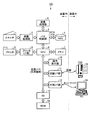
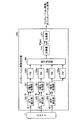
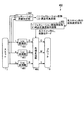
図1は、本実施形態にかかるMFP100の構成を示すブロック図である。図1に示すように、MFP100は、スキャナ1と、画像処理部2と、バス制御部3と、画像処理部4と、HDD5と、CPU6と、メモリ7と、プロッタI/F(インタフェース)部8と、プロッタ9と、操作表示部10と、回線I/F部11と、外部I/F部12と、SB(South Bridge)13と、ROM14と、を備えている。
FIG. 1 is a block diagram showing a configuration of the
スキャナ1は、CCD(Charge Coupled Device)などの光電変換素子からなるラインセンサと、A/D(アナログ/デジタル)コンバータと、ラインセンサおよびA/Dコンバータを駆動する駆動回路を備える。スキャナ1は、セットされた原稿をスキャンすることで得られる原稿の濃淡情報から、RGB各8ビットのデジタル画像データを生成して出力する。
The
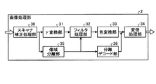
画像処理部2は、スキャナ1から出力されたデジタル画像データに対し、予め定めた特性に統一する処理を実行して出力する。図2は、画像処理部2の構成例を示すブロック図である。図2に示すように、画像処理部2は、スキャナ補正処理部30と、γ変換部31と、フィルタ処理部32と、色変換部33と、変倍処理部34と、像域分離部35と、分離デコード部36と、を備えている。
The
スキャナ補正処理部30は、スキャナ1から出力されたデジタル画像データに対し、シェーディング等、スキャナ1の機構上(照度歪み等)発生する読取りムラ等を補正する。
The scanner correction processing unit 30 corrects reading unevenness or the like that occurs on the mechanism of the scanner 1 (illuminance distortion or the like), such as shading, on the digital image data output from the
γ変換部31は、スキャナ1から受け取ったRGB画像データのγ特性を予め定められた特性(例えば、1/2.2乗)になるように変換する。
The γ conversion unit 31 converts the γ characteristic of the RGB image data received from the
フィルタ処理部32は、スキャナ1のMTF特性を補正する。また、フィルタ処理部32は、モアレを防止するために、読取画像の周波数特性を変えて、画像をくっきり、また滑らかにする。
The
色変換部33は、フィルタ処理部32から出力された画像データ値を、sRGBやopRGBのように予め定めた特性のRGB画像データ値に変換する。
The color conversion unit 33 converts the image data value output from the
変倍処理部34は、RGB画像データのサイズ(解像度)を予め定めた特性に統一する。変倍処理部34は、例えばRGB画像データのサイズ(解像度)を600dpiに変換する。 The scaling processing unit 34 unifies the size (resolution) of the RGB image data with predetermined characteristics. The scaling processing unit 34 converts, for example, the size (resolution) of RGB image data to 600 dpi.
基本的にγ変換部31と色変換部33での処理によって、特性が統一された画像データがMFP100内部に蓄積される。その後、再利用する場合に、蓄積された画像データは出力先の特性に適する画像信号に変換されるが、その詳細は後述する。
Basically, the image data whose characteristics are unified is accumulated in the
また、像域分離部35は、原稿の持つ特徴的なエリアの抽出を行う。例えば、像域分離部35は、一般的な印刷によって形成されている網点部の抽出、文字などのエッジ部の抽出、その画像データの有彩/無彩の判定、および、背景画像が白であるかの白背景の判定などを行う。
Further, the image
分離デコード部36は、像域分離部35から出力された像域分離信号を、画像処理部4での後段の処理に必要な情報量にデコードして出力する。像域分離信号は、例えば以下のような7ビットの信号である。
CH2:文字なか(1)/非文字なか(0)
CHR:文字(1)/非文字(0)
HT:高線数網点(1)/非高線数網点(0)
CW:有彩(1)/非有彩<無彩>(0)
WS:白地(1)/非白地(0)
LHT:低線数網点(1)/非低線数網点(0)
T:追跡パターン(1)/非追跡パターン(0)
The
CH2: Character (1) / Non-character (0)
CHR: Character (1) / Non-character (0)
HT: High line number halftone dot (1) / Non-high line number halftone dot (0)
CW: Aya (1) / Non Aya <Aya> (0)
WS: White (1) / Non-white (0)
LHT: Low line number halftone dot (1) / Non-low line number halftone dot (0)
T: tracking pattern (1) / non-tracking pattern (0)
分離デコード部36は、例えば、像域分離部35から出力された上記のような7ビットの像域分離信号を、{黒文字、色文字、文字なか、網点上文字、高線数網点、低線数網点、写真、追跡パターン}の各状態を3ビット、または、{黒文字、色文字、文字なか、非文字}の各状態を2ビットで表現できるようにデコードする。
The
バス制御部3は、MFP100内で必要な画像データや制御コマンド等の各種データのやり取りを行うデータバスの制御部である。バス制御部3は、複数種のバス規格間のブリッジ機能も有している。本実施形態では、バス制御部3は、画像処理部2、画像処理部4、および、CPU6とは、PCI−Expressバスで接続し、HDDとはATAバスで接続し、ASIC化している。
The
画像処理部4は、画像処理部2で予め定めた特性を統一されたデジタル画像データと付帯情報(本実施形態ではデコードされた像域分離信号)に対し、ユーザから指定される出力先に適した画像処理を実行して出力する。その詳細は後述する。
The
HDD5は、デスクトップパソコンにも使用されている電子データを保存するための大型の記憶装置である。HDD5は、MFP100内では主にデジタル画像データおよびデジタル画像データの付帯情報を蓄積する。また、本実施形態では、HDD5として、例えばIDEを拡張して規格化されているATAバス接続のハードディスクを使用する。
The
CPU6は、MFP100の制御全体を司るマイクロプロセッサである。本実施形態では、一例として近年普及してきたCPUコア単体に+αの機能を追加したインテグレーテッドCPUを使用する。例えば、PMC社のRM11100などの、汎用規格I/Fとの接続機能や、クロスバースイッチを使ったこれらバス接続機能がインテグレートされたCPUを使用できる。
The
メモリ7は、複数種のバス規格間をブリッジする際の速度差や、接続された部品自体の処理速度差を吸収するために、一時的にやりとりするデータを記憶する揮発性メモリである。また、メモリ7は、CPU6がMFP100を制御する際に、プログラムや中間処理データを一時的に記憶する。CPU6は高速処理を求められるため、通常起動時にROM14に記憶されたブートプログラムによってシステムを起動する。CPU6は、起動後は高速にアクセス可能なメモリ7に展開されたプログラムによって処理を行う。メモリ7は、例えば規格化されパーソナルコンピュータに使用されているDIMMを使用することができる。
The
プロッタI/F部8は、CPU6にインテグレートされた汎用規格I/F経由で送られてくるCMYKからなるデジタル画像データを受け取ると、プロッタ9の専用I/Fに出力するバスブリッジ処理を行う。汎用規格I/Fは、例えばPCI−Expressバスである。
When the plotter I /
プロッタ9は、CMYKからなるデジタル画像データを受け取ると、レーザービームを用いた電子写真プロセスを使って、転写紙に受け取った画像データを出力する。
When the
SB(サウスブリッジ)13は、パーソナルコンピュータに使用されるチップセットの1つとして用いられる汎用の電子デバイスである。SB13は、主にPCI−ExpressとISAブリッジとを含むCPUシステムを構築する際に使用されるバスのブリッジ機能を汎用回路化したものであり、本実施形態ではROM14との間をブリッジしている。
The SB (South Bridge) 13 is a general-purpose electronic device used as one of chip sets used in a personal computer. The
ROM14は、CPU6がMFP100の制御を行う際のプログラム(含むブート)を格納するメモリである。
The ROM 14 is a memory that stores a program (including boot) when the
操作表示部10は、MFP100とユーザとのインタフェースを行う部分であり、例えばLCD(液晶表示装置)とキースイッチとを備える。操作表示部10は、MFP100の各種状態や操作方法をLCDに表示し、ユーザによるキースイッチへの入力を検知する。操作表示部10は、例えばPCI−Expressバスを介してCPU6と接続する。
The
回線I/F部11は、PCI−Expressバスと電話回線とを接続する。回線I/F部11により、MFP100は電話回線を介して各種データのやり取りを行うことが可能になる。
The line I / F unit 11 connects a PCI-Express bus and a telephone line. The line I / F unit 11 allows the
FAX15は通常のファクシミリであり、電話回線を介してMFP100と画像データの授受を行う。
The FAX 15 is a normal facsimile, and exchanges image data with the
外部I/F部12は、PCI−Expressバスと外部装置とを接続する。外部I/F部12により、MFP100は外部装置と各種データのやり取りを行うことが可能になる。外部I/F部12は、例えば、その接続I/Fにネットワーク(イーサネット(登録商標))を使用することができる。すなわちMFP100は、外部I/F部12を介してネットワークに接続している。
The external I /
PC16は、いわゆるパーソナルコンピュータである。ユーザは、PC16にインストールされたアプリケーションソフトやドライバを介して、MFP100に対して各種制御や画像データの入出力を行う。
The
なお、画像処理部2や外部I/F部12から送られる特性が統一された画像データや像域分離信号等の付帯情報は、全てCPU6で符号化されてからHDD5に蓄積される。画像処理部4以降で処理する際には、HDD5に蓄積された画像データや付帯情報が復号されてから変換処理が実行される。ここで、特性が統一された画像データ(RGB)は非可逆なJPEG符号化等により高い圧縮率で処理を行い、像域分離信号等の付帯情報は可逆なK8符号化等で処理を行うことで、画質劣化を最小限に抑えている。
Note that image data sent from the
(コピー動作)
ユーザは、原稿をスキャナ1にセットし、操作表示部10により、所望する画質モード等の設定とコピー開始の入力を行う。
(Copy operation)
The user sets a document on the
操作表示部10は、ユーザから入力された情報を、MFP100内部の制御コマンドデータに変換し発行する。発行された制御コマンドデータはPCI−Expressバスを介してCPU6に通知される。
CPU6は、コピー開始の制御コマンドデータに従って、コピー動作プロセスのプログラムを実行し、コピー動作に必要な設定や動作を順に行っていく。以下に動作プロセスを順に記す。
The
スキャナ1で原稿をスキャンして得られたRGB各8ビットのデジタル画像データは、画像処理部2では、設定された画質モードに関係なく、前述した図2のスキャナ補正処理部30、γ変換部31、フィルタ処理部32、および色変換部33を経て、sRGBやROMM−RGBのように予め特性が定められたRGB信号に統一され、バス制御部3に送られる。
The 8-bit RGB digital image data obtained by scanning the document with the
また、分離デコード部36は、像域分離部35で生成された7ビットの像域分離信号を、設定された画質モードに応じて、画像処理部4での後段の処理に必要な情報にデコードして出力する。例えば、分離デコード部36は、上述のような7ビットの像域分離信号を、設定された画質モードに応じて、以下に示すような2ビットの属性情報(像域分離信号)にデコードする。
文字原稿モード:黒文字、色文字、文字なか、非文字
文字写真混在原稿モード:文字/非文字、有彩/無彩
写真原稿モード:有彩/無彩、白地/非白地
複写原稿モード:黒文字、色文字、白地、非文字
In addition, the
Text original mode: Black text, color text, text, non-character Text and photo mixed original mode: text / non-character, chromatic / achromatic Photo original mode: chromatic / achromatic, white / non-white Copy original mode: black text, Colored characters, white background, non-characters
バス制御部3は、画像処理部2から出力された統一RGB画像データと、設定された画像モードに応じて属性の異なる属性情報(像域分離信号)とを受け取ると、受け取ったRGB画像データおよび属性情報をCPU6を介して符号化してから、メモリ7およびHDD5に蓄積する。
When the
次に、メモリ7およびHDD5に蓄積されたRGB画像データおよび画素毎の属性情報は、CPU6で復号された後、バス制御部3を介して、画像処理部4に送られる。
Next, the RGB image data and the attribute information for each pixel accumulated in the
画像処理部4は、画素毎の属性情報に基づいて、受け取ったRGB画像データをプロッタ出力用のCMYK画像データに変換して出力する。
The
バス制御部3は、画像処理部4から出力されたCMYK画像データを受け取ると、CPU6を介してメモリ7に蓄積する。
When the
次に、メモリ7に蓄積されたCMYK画像データは、CPU6およびプロッタI/F部8を介して、プロッタ9に送られる。
Next, the CMYK image data stored in the
プロッタ9は、受け取ったCMYK画像データを転写紙に出力し、原稿のコピーが生成される。
The
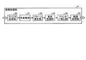
図3は、画像処理部4の構成例を示すブロック図である。図3に示すように、画像処理部4は、フィルタ処理部50と、色変換部51と、パターン発生部52と、変倍処理部53と、プリンタγ補正部54と、階調処理部55と、を備えている。以下、画像処理部4の動作を説明する。
FIG. 3 is a block diagram illustrating a configuration example of the
フィルタ処理部50は、統一RGB画像データの鮮鋭性を、プロッタ9に出力する場合の再現性が良くなるように補正する。具体的には、フィルタ処理部50は、設定された画質モードに応じてデコードされた属性情報(像域分離信号)に従って鮮鋭化処理または平滑化処理を実行する。例えば、フィルタ処理部50は、文字原稿モードでは文字をハッキリ/クッキリとするために鮮鋭化処理を実行する。また、フィルタ処理部50は、写真モードでは滑らかに階調性を表現するため平滑化処理を実行する。
The
色変換部51は、各8ビットの統一RGB画像データを受け取るとプロッタ9用の色空間であるCMYK各8ビットに変換する。このときにも、色変換部51は、設定された画質モード情報に応じてデコードされた属性情報(像域分離信号)に従って最適な色調整を実行する。
When the
変倍処理部53は、CMYK画像データのサイズ(解像度)を、プロッタ9の再現性能に従って変換する。プロッタ9の性能(解像度)によっては変倍処理部53が変換を行わなくてもよい。
The scaling
プリンタγ補正部54は、予めCPU6で生成され、プロッタ出力用に設定されたCMYK用のエッジ用γテーブルおよび非エッジ用γテーブルを用いて、CMYK版毎のテーブル変換を実行してγ補正を実行する。
The printer
階調処理部55は、プリンタγ補正部54から出力されたCMYK各8ビットを受け取るとプロッタ9の階調処理能力に従った階調数変換処理を行う。階調処理部55は、例えば、CMYK各2ビットに疑似中間調処理の1つである誤差拡散法を用いて階調数変換処理を行う。
When the
(ファックス送信動作)
ユーザは、原稿をスキャナ1にセットし、操作表示部10により、所望するモード等の設定とファックス開始の入力を行う。
(Fax transmission operation)
The user sets a document on the
操作表示部10は、ユーザから入力された情報を、MFP100内部の制御コマンドデータに変換し発行する。発行された制御コマンドデータは、PCI−Expressバスを介してCPU6に通知される。
CPU6は、ファックス送信開始の制御コマンドデータに従って、ファックス送信動作プロセスのプログラムを実行し、ファックス送信動作に必要な設定や動作を順に行っていく。以下に動作プロセスを順に記す。
The
スキャナ1で原稿をスキャンして得られたRGB各8ビットのデジタル画像データは、画像処理部2で予め定めた特性に統一されたRGB値に変換され、バス制御部3に送られる。
RGB 8-bit digital image data obtained by scanning the document with the
バス制御部3は、画像処理部2から出力されたRGB画像データを受け取ると、CPU6を介してメモリ7に蓄積する。
When the
次に、メモリ7に蓄積された統一RGB画像データは、CPU6およびバス制御部3を介して、画像処理部4に送られる。
Next, the unified RGB image data stored in the
画像処理部4は、受け取った統一RGB画像データを、ファックス送信用のモノクロ2値の画像データに変換し出力する。
The
バス制御部3は、画像処理部4から出力されたモノクロ2値画像データを受け取ると、CPU6を介してメモリ7に蓄積する。
When the
次に、メモリ7に蓄積されたモノクロ2値画像データは、CPU6を介して、回線I/F部11に送られる。
Next, the monochrome binary image data stored in the
回線I/F部11は、受け取ったモノクロ2値画像データを、回線を介して接続したFAX15に送信する。 The line I / F unit 11 transmits the received monochrome binary image data to the FAX 15 connected via the line.
(スキャナ配信動作)
ユーザは、原稿をスキャナ1にセットし、操作表示部10により、所望するモード等の設定とスキャナ配信開始の入力を行う。
(Scanner delivery operation)
The user sets a document on the
操作表示部10は、ユーザから入力された情報を、MFP100内部の制御コマンドデータに変換し発行する。発行された制御コマンドデータは、PCI−Expressバスを介してCPU6に通知される。
CPU6は、スキャナ配信開始の制御コマンドデータに従って、スキャナ配信動作プロセスのプログラムを実行し、スキャナ1は配信動作に必要な設定や動作を順に行っていく。以下に動作プロセスを順に記す。
The
スキャナ1で原稿をスキャンして得られたRGB各8ビットのデジタル画像データは、画像処理部2で予め定めた特性に統一されたRGB値に変換され、バス制御部3に送られる。
RGB 8-bit digital image data obtained by scanning the document with the
バス制御部3は、画像処理部2から出力された統一RGB画像データを受け取ると、CPU6を介してメモリ7に蓄積する。
Upon receiving the unified RGB image data output from the
次に、メモリ7に蓄積されたRGB画像データは、CPU6およびバス制御部3を介して、画像処理部4に送られる。
Next, the RGB image data stored in the
画像処理部4は、受け取ったRGB画像データを、sRGBのようなスキャナ配信用の画像データに変換し出力する(RGB多値、グレースケール、モノクロ2値等)。
The
バス制御部3は、画像処理部4から出力された画像データを受け取ると、CPU6を介してメモリ7に蓄積する。
When the
次に、メモリ7に蓄積された画像データは、CPU6を介して、外部I/F部12に送られる。
Next, the image data stored in the
外部I/F部12は、受け取った画像データを、ネットワークを介して接続したPC16に送信する。
The external I /
次に、原稿をスキャンした画像データをMFP100内に蓄積・保存し、その後、蓄積・保存した画像データを再利用する場合の動作を説明する。
Next, an operation when image data obtained by scanning a document is accumulated / saved in
(コピー動作+HDDへの蓄積・保存動作)
ユーザは、原稿をスキャナ1にセットし、操作表示部10により、所望する画質モード等の設定とコピー開始の入力を行う。
(Copy operation + Accumulation / save operation to HDD)
The user sets a document on the
操作表示部10は、ユーザから入力された情報を、MFP100内部の制御コマンドデータに変換し発行する。発行された制御コマンドデータは、PCI−Expressバスを介してCPU6に通知される。
CPU6は、コピー開始の制御コマンドデータに従って、コピー動作プロセスのプログラムを実行し、コピー動作に必要な設定や動作を順に行っていく。以下に動作プロセスを順に記す。
The
スキャナ1で原稿をスキャンして得られたRGB各8ビットのデジタル画像データは、画像処理部2では、設定された画質モードに関係なく、前述した図2のスキャナ補正処理部30、γ変換部31、フィルタ処理部32、および色変換部33を経て、sRGBやROMM−RGBのように予め特性が定められたRGB信号に統一され、バス制御部3に送られる。
The 8-bit RGB digital image data obtained by scanning the document with the
スキャナ補正処理部30は、スキャナ1から出力されたデジタル画像データに対し、シェーディング等、スキャナ1の機構上(照度歪み等)発生する読取りムラ等を補正する。
The scanner correction processing unit 30 corrects reading unevenness or the like that occurs on the mechanism of the scanner 1 (illuminance distortion or the like), such as shading, on the digital image data output from the
γ変換部31は、スキャナ1から受け取ったRGB画像データのγ特性を予め定められた特性(例えば、1/2.2乗)になるように変換する。
The γ conversion unit 31 converts the γ characteristic of the RGB image data received from the
フィルタ処理部32は、RGB画像データの鮮鋭性を予め定めた特性に統一する。例えば、フィルタ処理部32は、基準チャートをスキャンしたときに、線数毎に対して、設定された画質モード毎に予め定めたMTF特性値になるように変換する。その際、フィルタ処理部32は、像域分離部35で生成した像域分離信号に基づくパラメータを用いて処理を行う。
The
色変換部33は、フィルタ処理部32から出力された画像データ値を、sRGBやopRGBのように予め定めた特性のRGB画像データ値に変換する。
The color conversion unit 33 converts the image data value output from the
変倍処理部34は、RGB画像データのサイズ(解像度)を予め定めた特性(例えば600dpi)に統一する。 The scaling processing unit 34 unifies the size (resolution) of the RGB image data to a predetermined characteristic (for example, 600 dpi).
また、分離デコード部36は、像域分離部35で生成された7ビットの像域分離信号を、設定された画質モードに応じて、画像処理部4での後段の処理に必要な情報にデコードして出力する。例えば、分離デコード部36は、上述のような7ビットの像域分離信号を、設定された画質モードに応じて、以下に示すような2ビットの属性情報(像域分離信号)にデコードする。
文字原稿モード:黒文字、色文字、文字なか、非文字
文字写真混在原稿モード:文字/非文字、有彩/無彩
写真原稿モード:有彩/無彩、白地/非白地
複写原稿モード:黒文字、色文字、白地、非文字
In addition, the
Text original mode: Black text, color text, text, non-character Text and photo mixed original mode: text / non-character, chromatic / achromatic Photo original mode: chromatic / achromatic, white / non-white Copy original mode: black text, Colored characters, white background, non-characters
バス制御部3は、画像処理部2から出力された統一RGB画像データと設定された画像モードに応じて属性の異なる属性情報(像域分離信号)とを受け取ると、CPU6を介して符号化してから、メモリ7に蓄積する。
When the
メモリ7に蓄積した統一RGB画像データは、CPU6およびバス制御部3を介して、HDD5に送信され、HDD5内に画像入力条件(この場合、スキャナ入力や画質モード等)と共に蓄積・保存される。
The unified RGB image data stored in the
その後、前述のようにメモリ7の統一RGB画像データは、スキャナ読取り画像であることと、入力の際に設定された画質モードとを解釈して、画像処理部4によりプロッタ9に適した出力信号に変換されてから、プロッタ9に出力され、原稿のコピーが生成される。
After that, as described above, the unified RGB image data in the
ここで、図3を用いて、この時の動作を説明する。 Here, the operation | movement at this time is demonstrated using FIG.
フィルタ処理部50は、統一RGB画像データの鮮鋭性を、プロッタ9に出力する場合の再現性が良くなるように補正する。具体的には、フィルタ処理部50は、設定された画質モードに応じてデコードされた属性情報(像域分離信号)に従って鮮鋭化処理または平滑化処理を実行する。例えば、フィルタ処理部50は、文字原稿モードでは文字をハッキリ/クッキリとするために鮮鋭化処理を実行する。また、フィルタ処理部50は、写真モードでは滑らかに階調性を表現するため平滑化処理を実行する。
The
色変換部51は、各8ビットの統一RGB画像データを受け取るとプロッタ9用の色空間であるCMYK各8ビットに変換する。このときにも、設定された画質モード情報に応じてデコードされた属性情報(像域分離信号)に従って最適な色調整を実行する。
When the
変倍処理部53は、CMYK画像データのサイズ(解像度)を、プロッタ9の再現性能に従って変換する。プロッタ9の性能(解像度)によっては変倍処理部53が変換を行わなくてもよい。
The scaling
プリンタγ補正部54は、予めCPU6で生成され、プロッタ出力用に設定されたCMYK用のエッジ用γテーブル、非エッジ用γテーブルを用いて、CMYK版毎のテーブル変換を実行してγ補正を実行する。
The printer
階調処理部55は、CMYK各8ビットを受け取るとプロッタ9の階調処理能力に従った階調数変換処理を行う。
When the
また、画像蓄積時の別の動作として、CPU6は、メモリ7やHDD5の使用率を検出して、デコードされた属性情報を変更後に符号化して蓄積することもできる。
As another operation at the time of image storage, the
例えば、HDD5の使用率が規定値を超えている状態で画像が入力された場合、CPU6は、分離デコード部36から出力された属性情報(像域分離信号)の一部を破棄(例えば、下位ビットの全画素に0を設定)してから符号化して蓄積する。
For example, when an image is input in a state where the usage rate of the
この条件で動作した場合、例えば、設定された画質モードに応じて、以下に示すような属性情報(像域分離信号)に解釈される。 When operating under this condition, for example, the attribute information (image area separation signal) as described below is interpreted according to the set image quality mode.
(プリンタ動作+HDDへの蓄積・保存動作)
ユーザは、PC16上でDTP(Desk Top Publishing)のアプリケーションソフトウエアを動作させて、各種の文章や図形の作成および編集を行い、所望するプリンタ出力モード等の設定とプリント開始を指示する。PC16は、作成/編集された文書や図形を、ページ記述言語(PDL)で記述されたコマンドやデータ等の情報に変換してから、PDLデータを翻訳し、ラスタ画像データに変換するラスタイメージ処理(RIP)を行う。PC16は、ラスタ画像データを、外部I/F部12を介して、CPU6に送る。
(Printer operation + Accumulation / saving operation to HDD)
The user operates DTP (Desk Top Publishing) application software on the
PC16は、ラスタイメージ処理(RIP)の際、予め定めた特性の統一RGB画像データに変換すると同時に、以下に示すような4ビットの属性情報も発生させる。
CHR:文字・線画(1)/非文字・線画(0)
CW:有彩(1)/非有彩<無彩>(0)
WS:白地(1)/非白地(0)
HS:飽和色(1)/非飽和色(0)
At the time of raster image processing (RIP), the
CHR: Character / line drawing (1) / Non-character / line drawing (0)
CW: Aya (1) / Non Aya <Aya> (0)
WS: White (1) / Non-white (0)
HS: saturated color (1) / unsaturated color (0)
さらにPC16は、設定されたプリンタ出力モードに応じて、以下に示すような2ビットの属性情報にデコードしてから、デコードした属性情報を外部I/F部12を介して、CPU6に送る。
一般文書出力:イメージ以外の無彩色、イメージ以外の有彩色、イメージ、白地
グラフィック出力:無彩色、有彩色、白地、飽和色
写真画像出力:白地/非白地
Further, the
General document output: achromatic colors other than images, chromatic colors other than images, images, white background Graphic output: achromatic colors, chromatic colors, white background, saturated colors Photo image output: white background / non-white background
CPU6は、画像処理部2から出力された統一RGB画像データと設定された画像出力モードに応じて属性の異なる属性情報とを受け取ると、符号化してから、メモリ7に蓄積する。
When the
メモリ7に蓄積された統一RGB画像データは、CPU6およびバス制御部3を介して、HDD5に送信され、HDD5内に画像入力条件(この場合、プリンタ出力や画像出力モード等)と共に蓄積・保存される。
The unified RGB image data stored in the
その後、前述のようにメモリ7の統一RGB画像データは、プリンタ出力画像であることと、入力の際に設定された画像出力モードとを解釈して、画像処理部4によりプロッタ9に適した出力信号に変換されてから、プロッタ9に出力され、プリンタ出力画像が生成される。
After that, as described above, the unified RGB image data in the
色変換部51は、各8ビットの統一RGB画像データを受け取るとプロッタ9用の色空間であるCMYK各8ビットに変換する。このときにも、色変換部51は、設定された画質モード情報に応じてデコードされた属性情報に従った最適な色調整を実行する。
When the
変倍処理部53は、CMYK画像データのサイズ(解像度)を、プロッタ9の再現性能に従って変換する。プロッタ9の性能(解像度)によっては変倍処理部53が変換を行わなくてもよい。
The scaling
プリンタγ補正部54は、予めCPU6で生成され、プロッタ出力用に設定されたCMYK用のエッジ用γテーブル、非エッジ用γテーブルを用いて、CMYK版毎のテーブル変換を実行してγ補正を実行する。
The printer
階調処理部55は、CMYK各8ビットを受け取るとプロッタ9の階調処理能力と設定された画質モード情報に応じてデコードされた属性情報とに最適な階調数変換処理を行う。
Upon receiving 8 bits for each of CMYK, the
また、画像蓄積時の別の動作として、CPU6は、メモリ7やHDD5の使用率を検出して、デコードされた属性情報を変更後に符号化して蓄積することもできる。
As another operation at the time of image storage, the
次に、HDD5内に蓄積・保存した画像データを再利用する動作を説明する。
Next, an operation for reusing image data stored and stored in the
(ファックス送信動作)
ユーザは、操作表示部10により、先ほどコピー動作させた時にHDD5内に蓄積した画像データに対し、所望するモード等の設定とファックス送信開始の入力を行う。
(Fax transmission operation)
The user uses the
操作表示部10は、ユーザから入力された情報を、MFP100内部の制御コマンドデータに変換し発行する。発行された制御コマンドデータは、PCI−Expressバスを介してCPU6に通知される。
CPU6は、ファックス送信開始の制御コマンドデータに従って、ファックス送信動作プロセスのプログラムを実行し、ファックス送信動作に必要な設定や動作を順に行っていく。以下に動作プロセスを順に記す。
The
バス制御部3は、HDD5内に蓄積されているRGB画像データを、CPU6を介してメモリ7に出力する。
The
その後、前述のようにメモリ7のRGB画像データは、画像処理部4を介して回線I/F部11に出力され、FAX送信が実行される。図3を用いて、この時の動作を順に説明する。
Thereafter, as described above, the RGB image data in the
フィルタ処理部50は、RGB画像データの鮮鋭性を、FAX送信する場合の再現性が良くなるように補正する。具体的には、フィルタ処理部50は、所望するモード情報に従って鮮鋭化処理または平滑化処理を実行する。例えば、フィルタ処理部50は、文字モードでは文字をハッキリ/クッキリとするために鮮鋭化処理を実行し、写真モードでは滑らかに階調性を表現するため平滑化処理を実行する。
The
色変換部51は、RGB各8ビットのデータを受け取るとFAX装置で一般的な単色(モノクロ)8ビットに変換する。
When the
変倍処理部53は、モノクロ画像データのサイズ(解像度)を、FAX装置で送受されるサイズ(解像度)に変換する。例えば、変倍処理部53は、主走査:200dpi×副走査:100dpiに変換する。
The scaling
プリンタγ補正部54は、予めCPU6が設定したFAX送信用のγテーブルを用いて、γ補正を実行する。
The printer
階調処理部55は、モノクロ8ビットを受け取るとFAX装置で送受される階調処理能力に従った階調数変換処理を行う。例えば、階調処理部55は、疑似中間調処理の1つである誤差拡散法を用いて2値に階調数変換する。
When the
(スキャナ配信動作)
ユーザは、操作表示部10により、先ほどコピー動作させた時にHDD5内に蓄積した画像データに対し、所望するモード等の設定とスキャナ配信開始の入力を行う。
(Scanner delivery operation)
The user uses the
操作表示部10は、ユーザから入力された情報を、MFP100内部の制御コマンドデータに変換し発行する。発行された制御コマンドデータは、PCI−Expressバスを介してCPU6に通知される。
CPU6は、スキャナ配信開始の制御コマンドデータに従って、スキャナ配信動作プロセスのプログラムを実行し、スキャナ配信動作に必要な設定や動作を順に行っていく。以下に動作プロセスを順に記す。
The
バス制御部3は、HDD5内に蓄積されているRGB画像データを、CPU6を介してメモリ7に出力する。
The
その後、前述のようにメモリ7のRGB画像データは、画像処理部4を介して外部I/F装置(11)に出力され、スキャナ配信が実行される。図3を用いて、この時の動作を順に説明する。
Thereafter, as described above, the RGB image data in the
フィルタ処理部50は、RGB画像データの鮮鋭性を、スキャナ配信する場合の再現性が良くなるように補正する。具体的には、フィルタ処理部50は、所望するモード情報に従って鮮鋭化処理または平滑化処理を実行する。例えば、フィルタ処理部50は、文字モードでは文字をハッキリ/クッキリとするために鮮鋭化処理を実行し、写真モードでは滑らかに階調性を表現するため平滑化処理を実行する。
The
色変換部51は、RGB各8ビットのデータを受け取ると指定される色空間に変換する。例えば、色変換部51は、スキャナ配信で一般的なsRGB色空間に各色8ビットで変換する。
When the
変倍処理部53は、sRGB画像データのサイズ(解像度)を、指定されたスキャナ配信で送受されるサイズ(解像度)に変換する。例えば、変倍処理部53は、主走査:200dpi×副走査:200dpiに変換する。
The scaling
プリンタγ補正部54は、予めCPU6が設定した、配信用のγテーブルを用いて、γ補正を実行する。
The printer
階調処理部55は、指定されたスキャナ配信で送受される階調処理能力に従った階調数変換処理を行う。階調処理部55は、RGB各8ビットの16万色が指定されたものとして、階調処理は特に実行しなくてもよい。
The
以上のように、MFP100内に蓄積・保存したデータに対し、入力時と異なる出力先を所望した場合に、通常動作時(最初から出力先を指定したときの動作)と何ら画像品質が変わることなく出力先の変更が可能となっており、著しく再利用性が向上している。
As described above, when the output destination different from the input time is desired for the data stored / stored in the
(色変換処理部の構成)
図4は、本実施形態にかかる色変換処理部200の機能構成例を示すブロック図である。色変換処理部200は、スキャナ入力からコピー出力の一連の画像データに対する色変換処理を実行する。以下に述べるように、色変換処理部200は、上述の画像処理部2および画像処理部4に含まれる構成部と同様の機能を含む。色変換処理部200は、このような同様の機能を画像処理部2および画像処理部4と共通化するように構成してもよいし、画像処理部2および画像処理部4とは独立した構成部として構成してもよい。
(Configuration of color conversion processor)
FIG. 4 is a block diagram illustrating a functional configuration example of the color
図4に示すように、色変換処理部200は、スキャナγ補正部210と、色調整部220と、色相分割マスキング部230と、3D−LUT色変換部240と、パラメータ調整部250と、追跡パターン色出力予測部260と、を備えている。
As shown in FIG. 4, the color
スキャナγ補正部210は、スキャナ1から出力されたデジタル画像データに対し、予め定めた特性に統一するために、RGBの各画像読み取りデータを、一次元のルックアップテーブルを用いて、例えば、1/2.2乗になるようにγ変換する。スキャナγ補正部210は、図2のγ変換部31に相当する。
In order to unify the digital image data output from the
色調整部220は、統一RGBに色変換する前に色の調整を行う。色調整部220は、例えば、以下に示すように、RGB画像データをYuv画像データに変換し、uv信号の補正により彩度調整を実行する。
The
<RGB→Yuv変換>
Y=R1+2×G1+B1(Y:0〜1020)
U=R1−G1 (U:−255〜255)
V=B1−G1 (V:−255〜255)
<RGB → Yuv conversion>
Y = R1 + 2 × G1 + B1 (Y: 0 to 1020)
U = R1-G1 (U: -255 to 255)
V = B1-G1 (V: -255 to 255)
<彩度距離算出>
彩度距離(sat)は、uvの絶対値の和とする。
sat=|U|+|V|(sat:0〜510)
<Saturation distance calculation>
The saturation distance (sat) is the sum of the absolute values of uv.
sat = | U | + | V | (sat: 0 to 510)
<彩度距離からテーブルインデックスへの変換>
彩度距離(sat)の大きさを1/2にする。
INDEX=sat>>1
<Conversion from saturation distance to table index>
The saturation distance (sat) is halved.
INDEX = sat >> 1
<彩度変換率の設定>
得られたインデックスで変換テーブルを引いて、彩度変換率(conv_sat[INDEX])を求める。予め変換テーブルに設定される変換率は、最小0/64〜最大255/64で、係数分解能は1/64とする(8ビット)。よって、変換率1は64となる。
テーブル書き込み値=unsigned char(変換率×64)
<Saturation conversion rate setting>
The conversion table is subtracted from the obtained index to obtain the saturation conversion rate (conv_sat [INDEX]). The conversion rate preset in the conversion table is 0/64 to 255/64 at the minimum, and the coefficient resolution is 1/64 (8 bits). Therefore, the
Table write value = unsigned char (conversion rate x 64)
<彩度調整>
uvの距離に応じた彩度変換率(conv_sat[INDEX])をuvに乗じて彩度調整を行う。
U’=(U×conv_sat[INDEX])/24
V’=(V×conv_sat[INDEX])/24
<Saturation adjustment>
Saturation adjustment is performed by multiplying uv by a saturation conversion rate (conv_sat [INDEX]) corresponding to the distance of uv.
U ′ = (U × conv_sat [INDEX]) / 24
V ′ = (V × conv_sat [INDEX]) / 24
<Yuv→RGB変換>
彩度変換されたYUVデータをRGBデータに変換する。下記要領でクリップし、outRGBを求める。
G’=Y−((U’+V’)/22)
ただし、(G’<0:outG=0)、(G’≧1024:outG=255)、(0≦G’<1024:outG=G’>>2)
R’=U’+G’
ただし、(B’<0:outB=0)、(B’≧1024:outB=255)、(0≦B’<1024:outB=B’>>2)
B’=V’+G’
ただし、(R’<0:outR=0)、(R’≧1024:outR=255)、(0≦R’<1024:outR=R’>>2)
<Yuv → RGB conversion>
The chroma-converted YUV data is converted into RGB data. Clip outRGB as follows.
G ′ = Y − ((U ′ + V ′) / 22)
However, (G ′ <0: outG = 0), (G ′ ≧ 1024: outG = 255), (0 ≦ G ′ <1024: outG = G ′ >> 2)
R '= U' + G '
However, (B ′ <0: outB = 0), (B ′ ≧ 1024: outB = 255), (0 ≦ B ′ <1024: outB = B ′ >> 2)
B '= V' + G '
However, (R ′ <0: outR = 0), (R ′ ≧ 1024: outR = 255), (0 ≦ R ′ <1024: outR = R ′ >> 2)
色相分割マスキング部230は、予め定めた特性に統一するために、γ変換後のRGBデータに対して、色相成分を算出して、色相毎に分割した領域毎に設定されたマスキング係数を用いて線形変換する。色相分割マスキング部230は、図2の色変換部33に相当する。
The hue
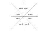
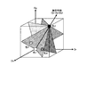
RGBデータに対する色相の分割は、図5に示すように、無彩色軸(Dr=Dg=Db)を中心として放射状に拡がる平面で色空間を分割する。 As shown in FIG. 5, the hue division for the RGB data divides the color space by a plane extending radially around the achromatic color axis (Dr = Dg = Db).
具体的な色相判定は、画像信号(snpr,snpg,snpb)を色相信号(HUE)に変換して色相境界値(HUE00〜11)と比較し、その結果により色相領域(12分割)を判定して色相領域信号(Huejo)を出力することで実現する。 Specifically, the hue determination is performed by converting an image signal (snpr, snpg, snpb) into a hue signal (HUE) and comparing it with a hue boundary value (HUE00 to 11), and determining the hue region (12 divisions) based on the result. This is realized by outputting a hue area signal (Huejo).
<色差信号生成>
画像信号(snpr,snpg,snpb)から色差信号(X,Y)を生成する。
X=snpg−snpr
Y=snpb−snpg
<Color difference signal generation>
Color difference signals (X, Y) are generated from the image signals (snpr, snpg, snpb).
X = snpg-snpr
Y = snpb-snpg
<広域色相検出>
色差信号(X,Y)から、広域色相信号(HUEH)を生成する。広域色相信号(HUEH)は、X−Y信号平面を8分割した時の位置(図6参照)を示す。広域色相は、以下の条件式にて検出する。
!HT1かつHT0:HUEH=0
!HT2かつHT1:HUEH=1
!HT3かつHT2:HUEH=2
!HT4かつHT3:HUEH=3
!HT5かつHT4:HUEH=4
!HT6かつHT5:HUEH=5
!HT7かつHT6:HUEH=6
!HT0かつHT7:HUEH=7
上記以外(Y=X=0):HUEH=7
<Wide area hue detection>
A wide-range hue signal (HUEH) is generated from the color difference signal (X, Y). The wide area hue signal (HUEH) indicates a position when the XY signal plane is divided into eight (see FIG. 6). The wide-range hue is detected by the following conditional expression.
! HT1 and HT0: HUEH = 0
! HT2 and HT1: HUEH = 1
! HT3 and HT2: HUEH = 2
! HT4 and HT3: HUEH = 3
! HT5 and HT4: HUEH = 4
! HT6 and HT5: HUEH = 5
! HT7 and HT6: HUEH = 6
! HT0 and HT7: HUEH = 7
Other than above (Y = X = 0): HUEH = 7
ただし、HT0からHT7は以下の通り。
HT0=(Y≧0)
HT1=(Y≧X)
HT2=(X≦0)
HT3=(Y≦−X)
HT4=(Y≦0)
HT5=(Y≦X)
HT6=(X≧0)
HT7=(Y≧−X)
However, HT0 to HT7 are as follows.
HT0 = (Y ≧ 0)
HT1 = (Y ≧ X)
HT2 = (X ≦ 0)
HT3 = (Y ≦ −X)
HT4 = (Y ≦ 0)
HT5 = (Y ≦ X)
HT6 = (X ≧ 0)
HT7 = (Y ≧ −X)
<色差信号回転>
広域色相信号(HUEH)に応じて色差信号(XA,YA)を生成する。色差信号(XA,YA)は、色差信号平面(X,Y)を回転して、“HUEH=0”の領域に移動させた時の座標である。
HUEH=0のとき:XA=X,YA=Y
HUEH=1のとき:XA=X+Y,YA=−X+Y
HUEH=2のとき:XA=Y,YA=−X
HUEH=3のとき:XA=−X+Y,YA=−X−Y
HUEH=4のとき:XA=−X,YA=−Y
HUEH=5のとき:XA=−X−Y,YA=X−Y
HUEH=6のとき:XA=−Y,YA=X
HUEH=7のとき:XA=X−Y,YA=X+Y
<Color difference signal rotation>
Color difference signals (XA, YA) are generated according to the wide-range hue signal (HUEH). The color difference signals (XA, YA) are coordinates when the color difference signal plane (X, Y) is rotated and moved to the area of “HUEH = 0”.
When HUEH = 0: XA = X, YA = Y
When HUEH = 1: XA = X + Y, YA = −X + Y
When HUEH = 2: XA = Y, YA = −X
When HUEH = 3: XA = −X + Y, YA = −X−Y
When HUEH = 4: XA = −X, YA = −Y
When HUEH = 5: XA = −XY, YA = XY
When HUEH = 6: XA = −Y, YA = X
When HUEH = 7: XA = X−Y, YA = X + Y
<狭域色相検出>
色差信号(XA,YA)から狭域色相信号(HUEL)を生成する。狭域色相信号(HUEL)は、色差信号平面座標の傾き(HUEL/32=YA/XA)である。
XAが0:HUEL=0x1F
上記以外:HUEL=(YA<<5)/XA
<Narrow hue detection>
A narrow-range hue signal (HUEL) is generated from the color difference signals (XA, YA). The narrow-range hue signal (HUEL) is the slope of the color difference signal plane coordinates (HUEL / 32 = YA / XA).
XA is 0: HUEL = 0x1F
Other than the above: Huel = (YA << 5) / XA
<色相境界レジスタ>
色相境界レジスタ(HUE00〜HUE11)設定値を出力する。
<Hue boundary register>
Hue boundary registers (HUE00 to HUE11) set values are output.
<色相領域判定>
色相境界信号(HUE00〜HUE11:8ビット)を色相信号(HUEHL{HUEH,HUEL})と比較して、色相領域(HUE)を生成する。
HUE00<HUEHL≦HUE01:HUE=1
HUE01<HUEHL≦HUE02:HUE=2
HUE02<HUEHL≦HUE03:HUE=3
HUE03<HUEHL≦HUE04:HUE=4
HUE04<HUEHL≦HUE05:HUE=5
HUE05<HUEHL≦HUE06:HUE=6
HUE06<HUEHL≦HUE07:HUE=7
HUE07<HUEHL≦HUE08:HUE=8
HUE08<HUEHL≦HUE09:HUE=9
HUE09<HUEHL≦HUE10:HUE=10
HUE10<HUEHL≦HUE11:HUE=11
上記以外 :HUE=0
<Hue area determination>
The hue boundary signal (HUE00 to HUE11: 8 bits) is compared with the hue signal (HUEHL {HUEH, HUEL}) to generate a hue region (HUE).
HUE00 <HUEHL ≦ HUE01: HUE = 1
HUE01 <HUEHL ≦ HUE02: HUE = 2
HUE02 <HUEHL ≦ HUE03: HUE = 3
HUE03 <HUEHL ≦ HUE04: HUE = 4
HUE04 <HUEHL ≦ HUE05: HUE = 5
HUE05 <HUEHL ≦ HUE06: HUE = 6
HUE06 <HUEHL ≦ HUE07: HUE = 7
HUE07 <HUEHL ≦ HUE08: HUE = 8
HUE08 <HUEHL ≦ HUE09: HUE = 9
HUE09 <HUEHL ≦ HUE10: HUE = 10
HUE10 <HUEHL ≦ HUE11: HUE = 11
Other than above: HUE = 0
なお、最後の条件は(HUE11<HUEHL)&&(HUEHL≦HUE00)と等価となる。 The last condition is equivalent to (HUE11 <HUEHL) && (HUEHL ≦ HUE00).
<色相分割マスキング>
色相領域判定された色相HUEに基づき、色相に応じたマスキング演算を行う。本実施形態では、スキャナRGBから統一RGBへのマスキング演算が行われる。
<Hue division masking>
Based on the hue HUE determined for the hue area, a masking operation corresponding to the hue is performed. In this embodiment, a masking operation from the scanner RGB to the unified RGB is performed.
ここで、12色相分割の線形マスキングの積和演算を行う場合、各演算は、RGBの各色毎に独立に処理される。色相領域判定により算出された色相判定信号HUEに基づいて、色補正係数と色補正定数を選択し演算する。
sum_X=coef_r[HUE]×bcr+coef_g[HUE]×bcg+coef_b[HUE]×bcb+const×256+128(X:RGBK)
Msk_X=sum_X>>8(X:RGBK)
Here, when performing a product-sum operation for linear masking with 12 hue divisions, each operation is processed independently for each color of RGB. Based on the hue determination signal HUE calculated by the hue area determination, a color correction coefficient and a color correction constant are selected and calculated.
sum_X = coef_r [HUE] × bcr + coef_g [HUE] × bcg + coef_b [HUE] × bcb + const × 256 + 128 (X: RGBK)
Msk_X = sum_X >> 8 (X: RGBK)
図4の3D−LUT色変換部240は、コピー動作の場合、統一RGB画像データに基づいて、プロッタ制御向けのCMYK画像データに変換する。3D−LUT色変換部240は、図3の色変換部51に相当する。
In the case of a copy operation, the 3D-LUT
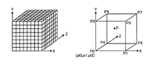
コピー(プロッタ)出力動作の場合、三次元LUT変換を実行して、プロッタ9の出力色(CMYK)への変換が実行される。三次元LUTによる変換アルゴリズムには、例えば従来から広く使用されているメモリマップ補間法を用いることができる。
In the case of a copy (plotter) output operation, three-dimensional LUT conversion is executed, and conversion to the output color (CMYK) of the
入力されたu_8ビットの統一RGB画像データ(In_r、In_g、In_b)に対して、三次元メモリマップ補間が実行される。 Three-dimensional memory map interpolation is performed on the input u_8-bit unified RGB image data (In_r, In_g, In_b).
メモリマップ補間では、三次元入力色空間を複数の単位立方体に分割し、分割した各単位立方体を、対称軸を共有している6個の四面体に分割し、単位立方体毎に線形演算によって出力値を求める。線形演算には分割境界の点(=格子点)のデータをパラメータとして用いる(以下、格子点パラメータと呼ぶ)。実際の処理手順は以下の通り(出力版毎に同一処理を実行する)。なお、本三次元メモリマップ補間では8分割としているので、単位立方体の一辺の長さは32となる。 In memory map interpolation, the three-dimensional input color space is divided into a plurality of unit cubes, each divided unit cube is divided into six tetrahedrons that share the axis of symmetry, and output by linear operation for each unit cube. Find the value. In the linear operation, data of division boundary points (= lattice points) are used as parameters (hereinafter referred to as lattice point parameters). The actual processing procedure is as follows (the same processing is executed for each output version). In this three-dimensional memory map interpolation, the length of one side of the unit cube is 32 because it is divided into eight.
入力データをX(X,Y,z)としたとき、まずその座標Xを内包する単位立方体を選択する。ここでは、X(X,Y,z)=(In_r、In_g、In_b)となる。 When the input data is X (X, Y, z), first, a unit cube containing the coordinate X is selected. Here, X (X, Y, z) = (In_r, In_g, In_b).
選択された単位立方体内での座標Pの下位座標(Δx,Δy,Δz)を求め、下位座標の大小比較により単位四面体を選択し、単位四面体毎に線形補間を実行して、座標Pでの出力値Poutを求める。Poutは式全体を単位立方体の一辺の長さを乗算して整数値にしておく。 The lower coordinates (Δx, Δy, Δz) of the coordinate P in the selected unit cube are obtained, the unit tetrahedron is selected by comparing the lower coordinates, the linear interpolation is performed for each unit tetrahedron, and the coordinates P The output value Pout at is obtained. Pout is an integer value obtained by multiplying the entire expression by the length of one side of the unit cube.
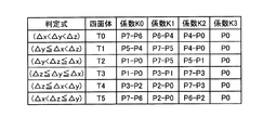
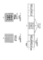
図7のP0〜P7は、格子点出力値(ここでは、統一RGBの色に対応するプロッタ9のデバイスCMYKに相当)である。補間係数K0、K1、K2、K3は、Δx、Δy、Δzの大小関係、および前述の分離信号に従って決定する。
P0 to P7 in FIG. 7 are grid point output values (here, corresponding to the device CMYK of the
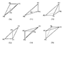
図8は、補間用四面体に補間で用いられる格子点で張られる四面体を示す図である。図9は、補間係数の決定ルールを示す図である。 FIG. 8 is a diagram showing a tetrahedron stretched by lattice points used in the interpolation tetrahedron. FIG. 9 is a diagram illustrating a rule for determining an interpolation coefficient.
最終的に、選択された四面体の4点の予め設定された頂点上の出力値と入力の四面体の中の位置(各頂点からの距離)に基づいて、以下に示す式により線形補間が実行される。
Pout_c=(K0_c×Δx+K1_c×Δy+K2_c×Δz+K3_c)<<5
Pout_m=(K0_m×Δx+K1_m×Δy+K2_m×Δz+K3_m)<<5
Pout_y=(K0_y×Δx+K1_y×Δy+K2_y×Δz+K3_y)<<5
Pout_k=(K0_k×Δx+K1_k×Δy+K2_k×Δz+K3_k)<<5
Finally, based on the output values on the four preset vertices of the selected tetrahedron and the position (distance from each vertex) in the input tetrahedron, linear interpolation is performed by the following formula: Executed.
Pout_c = (K0_c × Δx + K1_c × Δy + K2_c × Δz + K3_c) << 5
Pout_m = (K0_m × Δx + K1_m × Δy + K2_m × Δz + K3_m) << 5
Pout_y = (K0_y × Δx + K1_y × Δy + K2_y × Δz + K3_y) << 5
Pout_k = (K0_k × Δx + K1_k × Δy + K2_k × Δz + K3_k) << 5
図4の操作表示部10は、図1と同様にMFP100とユーザのインタフェースを行う部分である。本実施形態では、コピー動作で、原稿種類や好みの仕上がり(濃度設定など)に関する条件や色加工条件を含む画像出力条件が操作表示部10を用いて設定される。設定された画像出力条件はバスを介してCPU6に送られる。
The
追跡パターン色出力予測部260は、前述の操作表示部10で設定された画像出力条件を受け付ける(受付部)。そして、追跡パターン色出力予測部260は、受け付けた画像出力条件下の入力色や前述した各処理部(スキャナγ補正部210、色調整部220、色相分割マスキング部230、3D−LUT色変換部240)の色補正パラメータを形成する代表入力色に対して、追跡パターンを付加したときの色の変化を予測して、設定された画像出力条件下の通常の出力色と、追跡パターンが付加された入力色に対する出力色との色差(ΔE)を算出する(算出部)。追跡パターン色出力予測部260は、算出した色差をパラメータ調整部250に送る。なお、通常の出力色とは、追跡パターンが付加されない入力色に対する出力色を意味する。また、色補正パラメータとは、MFP100内で扱う色信号に対する調整および加工(RGB→R’G’B’など)および色の属性(RGBやCMYK)の変換式で使用する各係数および係数算出のベースとなるパラメータの総称である。
The tracking pattern color
追跡パターン色出力予測部260は、例えば、以下のようにして色差ΔEを算出する。
ΔE={(L1−L2)2+(a1−a2)2+(b1−b2)2}0.5
ただし、
L1a1b1:通常の入力色に対する画像出力条件下の出力色のCIELAB値
L2a2b2:追跡パターンが付加された入力色に対する画像出力条件下の出力色のCIELAB値
The tracking pattern color
ΔE = {(L1-L2) 2 + (a1-a2) 2 + (b1-b2) 2 } 0.5
However,
L1a1b1: CIELAB value of the output color under the image output condition with respect to the normal input color L2a2b2: CIELAB value of the output color under the image output condition with respect to the input color to which the tracking pattern is added
パラメータ調整部250は、前述した各処理部(スキャナγ補正部210、色調整部220、色相分割マスキング部230、3D−LUT色変換部240)の色補正パラメータに対して、後述するような演算および調整を実行して各処理部のレジスタに設定する。
The
例えば、パラメータ調整部250は、2色コピーモードでは、スキャナ1で読取る原稿画像の鮮やかな色(各色相の飽和色)の部分は黄色で出力して、原稿画像の無彩(グレー)側への階調変化を黒(Black)で表現して、原稿画像の無彩(グレー)は黒(Black)1色で再現する。なお、2色コピーモードとは、原稿の黒部分以外を黄色(Yellow)、原稿の黒(無彩色)部分を黒(Black)で再現するモードである。
For example, in the two-color copy mode, the
したがって、スキャナ1で読取った原稿が複写原稿の場合、追跡パターンとして黄色(Yellow)ドット(パターン)が画像全面に書き込まれている。このため、例えば、原稿の中に高彩度の青系(特にCyan)の領域が存在すると、黄色(Yellow)ドット(パターン)の影響で彩度(鮮やかさ)が低下しながら、緑(Green)方向に色がシフトすることで、2色コピーに追跡パターンが黒(Black)ドットとして現れて、人に認識されてしまう。
Therefore, when the document read by the
追跡パターン色出力予測部260は、入力色空間内の代表色に対して、通常の2色コピーモード時の出力色のCIELAB値と、追跡パターンが付加された入力色空間内の代表色に対する2色コピーモード時の出力色のCIELAB値とから、前述の色差(ΔE)を算出する。算出された色差(ΔE)が予め設定された許容色差より大きくなった場合、パラメータ調整部250は、前述した各処理部(スキャナγ補正部210、色調整部220、色相分割マスキング部230、3D−LUT色変換部240)の色補正パラメータを調整して各処理部のレジスタに設定する(詳細は後述)。
The tracking pattern color
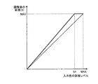
この画像出力条件である2色コピーモードでは、追跡パターンの付加による彩度低下が色差を増大させている。このため、前述した色調整部220のパラメータが図10に示す彩度変換特性になるように、前述のパラメータテーブル(conv_sat[INDEX])を変更する。
In the two-color copy mode that is the image output condition, the color difference is increased due to a decrease in saturation due to the addition of the tracking pattern. Therefore, the parameter table (conv_sat [INDEX]) described above is changed so that the parameters of the
なお、図10のS1は、入力色の彩度(本実施形態ではUVの和)に対して彩度を飽和させる彩度レベルを表す。S1の設定方法としては、例えば、入力色空間内の代表色で、追跡パターンの付加による彩度低下により前述の色差が許容色差を超えた追跡パターンが付加された入力色の彩度(実施形態ではUVの和)とする方法が一例として挙げられる。 Note that S1 in FIG. 10 represents a saturation level at which the saturation is saturated with respect to the saturation of the input color (in this embodiment, the sum of UVs). As a setting method of S1, for example, the saturation of an input color to which a tracking pattern in which the above-described color difference exceeds an allowable color difference due to a decrease in saturation due to the addition of the tracking pattern is added to the representative color in the input color space (the embodiment) Then, the method of UV sum) is an example.
ここで、追跡パターン色出力予測部260の入力色空間内の代表色に対する追跡パターン付加後の色(本実施形態では、図4のスキャナγ補正後のR’G’B’の値となる)は、予め求めて代表色としてテーブル化して記憶しておいてもよい。また、ニューラルネットワークを用いて予め構築したCMY(K)に対する混色シミュレータを用いて、追跡パターン付加後の色を推定しても構わない。 Here, the color after the tracking pattern is added to the representative color in the input color space of the tracking pattern color output prediction unit 260 (in this embodiment, the value is R′G′B ′ after scanner γ correction in FIG. 4). May be obtained in advance and stored in a table as a representative color. Further, the color after adding the tracking pattern may be estimated using a color mixing simulator for CMY (K) constructed in advance using a neural network.
また、色差ΔEの算出で扱うCIELAB値(L1a1b1とL2a2b2)は、通常の代表入力色R1G1B1(本実施形態では、図4のスキャナγ補正後のRGB値)、および、追跡パターンが付加された代表入力色R2G2B2(本実施形態では、図4のスキャナγ補正後のRGB値)に対して、色相分割マスキング部230によって、後述する2色コピーモード用の色相分割マスキング係数を用いて、統一RGB値で示された2色への色分解結果に変換される。
The CIELAB values (L1a1b1 and L2a2b2) handled in the calculation of the color difference ΔE are the typical representative input color R1G1B1 (in this embodiment, the RGB values after the scanner γ correction in FIG. 4), and the representative to which the tracking pattern is added. For the input color R2G2B2 (in this embodiment, the RGB value after the scanner γ correction in FIG. 4), the hue
これら色変換された2色への色分解結果は、統一RGBになっている。このため、仮に統一RGBをsRGBと仮定した場合、前述のL1a1b1とL2a2b2は、以下のように三刺激値(CIEXYZ)を介して色変換される。
X1=0.4124×r1+0.3576×g1+0.1805×b1
Y1=0.2126×r1+0.7152×g1+0.0722×b1
Z1=0.0193×r1+0.1192×g1+0.9505×b1
X2=0.4124×r2+0.3576×g2+0.1805×b2
Y2=0.2126×r2+0.7152×g2+0.0722×b2
Z2=0.0193×r2+0.1192×g2+0.9505×b2
The result of color separation into these two color-converted colors is unified RGB. For this reason, assuming that the unified RGB is sRGB, the above-described L1a1b1 and L2a2b2 are color-converted via the tristimulus values (CIEXYZ) as follows.
X1 = 0.4124 × r1 + 0.3576 × g1 + 0.1805 × b1
Y1 = 0.2126 × r1 + 0.7152 × g1 + 0.0722 × b1
Z1 = 0.0193 × r1 + 0.1192 × g1 + 0.9505 × b1
X2 = 0.4124 * r2 + 0.3576 * g2 + 0.1805 * b2
Y2 = 0.2126 * r2 + 0.7152 * g2 + 0.0722 * b2
Z2 = 0.0193 * r2 + 0.1192 * g2 + 0.9505 * b2
ここで、
r1=(R1/1023)2.2
g1=(G1/1023)2.2
b1=(B1/1023)2.2
r2=(R2/1023)2.2
g2=(G2/1023)2.2
b2=(B2/1023)2.2
here,
r1 = (R1 / 1023) 2.2
g1 = (G1 / 1023) 2.2
b1 = (B1 / 1023) 2.2
r2 = (R2 / 1023) 2.2
g2 = (G2 / 1023) 2.2
b2 = (B2 / 1023) 2.2
L1=116×(Y1/Y0)1/3−16
a1=500×{(X1/X0)1/3−(Y1/Y0)1/3}
B1=500×{(Y1/Y0)1/3−(Z1/Z0)1/3}
L2=116×(Y2/Y0)1/3−16
a2=500×{(X2/X0)1/3−(Y2/Y0)1/3}
B2=500×{(Y2/Y0)1/3−(Z2/Z0)1/3}
L1 = 116 × (Y1 / Y0) 1/3 −16
a1 = 500 × {(X1 / X0) 1/3 − (Y1 / Y0) 1/3 }
B1 = 500 × {(Y1 / Y0) 1/3 − (Z1 / Z0) 1/3 }
L2 = 116 × (Y2 / Y0) 1/3 −16
a2 = 500 × {(X2 / X0) 1/3 − (Y2 / Y0) 1/3 }
B2 = 500 × {(Y2 / Y0) 1/3 − (Z2 / Z0) 1/3 }
(色変換処理部200の色補正動作)
図4の色相分割マスキング部230で使用する各色相のマスキング係数は、無彩色軸上の2点と両境界平面上の2点(合計4点)の(Dr,Dg,Db)→(Dc,Dm,Dy,Dk)の対応関係が判れば決定できる。
(Color correction operation of the color conversion processing unit 200)
The masking coefficients for each hue used in the hue
ここでは、入力色をRGB(スキャナベクタ)、出力色(対応色)をCMYK(プリンタベクタ)と定義して説明するが、入出力データの属性は任意に設定でき、汎用的な色変換が可能である。 Here, the input color is defined as RGB (scanner vector) and the output color (corresponding color) is defined as CMYK (printer vector). However, the input / output data attributes can be set arbitrarily, and general-purpose color conversion is possible. It is.
本実施形態では、スキャナγ補正後のRGBがスキャナベクタ、統一RGB(sRGB等)がプリンタベクタに相当する。また、スキャナベクタ(入力色)に対するプリンタベクタ(対応色)を、画像出力モードに応じて切り換えたり、色補正(色調整や色加工)に応じて変更してからマスキング係数を求めることで、効率的に多様な色補正に対応している。 In the present embodiment, RGB after scanner γ correction corresponds to a scanner vector, and unified RGB (sRGB or the like) corresponds to a printer vector. In addition, the printer vector (corresponding color) for the scanner vector (input color) can be switched according to the image output mode, or changed according to color correction (color adjustment or color processing), and then the masking coefficient can be obtained. It corresponds to various color corrections.
図11で、4点の(Dr,Dg,Db)と(Dc,Dm,Dy,Dk)との対応が以下の(1)式で表されるとする。
この場合、色1〜色4それぞれの対応をまとめて、以下の(2)式のように対応付ける。
(2)式の対応を結び付けるマスキング係数は、以下の(3)式のようになる。
最終的に求めるマスキング係数は、RGBの逆行列により、以下の(4)式のようになる。
このように無彩色軸上の2点(白と黒)と両境界平面上の2点(合計4点)の関係が決まれば、マスキング係数が求まる。このため、色変換のパラメータ設計としては、入出力データの属性に関わらず、(1)式の右辺をスキャナベクタ、左辺をプリンタベクタとして定義し、各分割点のスキャナベクタおよびプリンタベクタを求めることになる。 If the relationship between two points on the achromatic axis (white and black) and two points on both boundary planes (four points in total) is determined in this way, a masking coefficient can be obtained. Therefore, as a parameter design for color conversion, the right side of equation (1) is defined as the scanner vector and the left side is defined as the printer vector regardless of the input / output data attributes, and the scanner vector and printer vector at each division point are obtained. become.
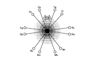
色相分割マスキング色変換では、R、G、B、C、M、Yに対しそれぞれ2点の計12点の色空間の分割点で分割を行っている(図12参照)。したがって、図13に示す無彩色軸上の白および黒点を含めた14点の最終的なスキャナベクタおよびプリンタベクタを設定後、色相領域毎にマスキング係数を算出する。 In the hue division masking color conversion, R, G, B, C, M, and Y are divided at two division points in a total of 12 color spaces (see FIG. 12). Therefore, after setting 14 final scanner vectors and printer vectors including white and black points on the achromatic color axis shown in FIG. 13, a masking coefficient is calculated for each hue region.
<シングルカラー出力動作に対する対応色(プリンタベクタ)の設定>
フルカラー用の基本スキャナベクタと基本プリンタベクタが図13のように設定されている場合、シングルカラー向けの設定色としてプリンタベクタ(Xr’,Xg’,Xb’,Xk’)を、以下のように色相ごとに振り分ける。その後、基本スキャナベクタをベースに算出したライトネスを各成分(R,G,B,K)に乗じて、最終的なシングルカラー用のプリンタベクタとして設定して、マスキング係数を前述のように算出する。そして、算出したマスキング係数を色相分割マスキング部230に設定する。
<Setting of corresponding color (printer vector) for single color output operation>
When the basic scanner vector and the basic printer vector for full color are set as shown in FIG. 13, the printer vectors (Xr ′, Xg ′, Xb ′, Xk ′) are set as the set colors for single color as follows: Sort by hue. After that, the lightness calculated based on the basic scanner vector is multiplied by each component (R, G, B, K) to set as a final single color printer vector, and the masking coefficient is calculated as described above. . The calculated masking coefficient is set in the hue
(無彩色)
W(Xr’,Xg’,Xb’,Xk’)×[{(Wr−Wr)×sr+(Wg−Wg)×sg+(Wb−Wb)×sb}/(sr+sg+sb)/1024]
K(Xr’,Xg’,Xb’,Xk’)×[{(Kr−Wr)×sr+(Kg−Wg)×sg+(Kb−Wb)×sb}/(sr+sg+sb)/1024]
(有彩色)
Rm(Xr’,Xg’,Xb’,Xk’)×[{(Rmr−Wr)×sr+(Rmg−Wg)×sg+(Rmb−Wb)×sb}/(sr+sg+sb)/1024]
Ry(Xr’,Xg’,Xb’,Xk’)×[{(Ryr−Wr)×sr+(Ryg−Wg)×sg+(Ryb−Wb)××sb}/(sr+sg+sb)/1024]
Yr(Xr’,Xg’,Xb’,Xk’)×[{(Yrr−Wr)×sr+(Yrg−Wg)×sg+(Yrb−Wb)×sb}/(sr+sg+sb)/1024]
Yg(Xr’,Xg’,Xb’,Xk’)×[{(Ygr−Wr)×sr+(Ygg−Wg)×sg+(Ygb−Wb)×sb}/(sr+sg+sb)/1024]
Gy(Xr’,Xg’,Xb’,Xk’)×[{(Gyr−Wr)×sr+(Gyg−Wg)×sg+(Gyb−Wb)×sb}/(sr+sg+sb)/1024]
Gc(Xr’,Xg’,Xb’,Xk’)×[{(Gcr−Wr)×sr+(Gcg−Wg)×sg+(Gcb−Wb)×sb}/(sr+sg+sb)/1024]
Cg(Xr’,Xg’,Xb’,Xk’)×[{(Cgr−Wr)×sr+(Cgg−Wg)×sg+(Cgb−Wb)×sb}/(sr+sg+sb)/1024]
Cb(Xr’,Xg’,Xb’,Xk’)×[{(Cbr−Wr)×sr+(Cbg−Wg)×sg+(Cbb−Wb)×sb}/(sr+sg+sb)/1024]
Bc(Xr’,Xg’,Xb’,Xk’)×[{(Bcr−Wr)×sr+(Bcg−Wg)×sg+(Bcb−Wb)×sb}/(sr+sg+sb)/1024]
Bm(Xr’,Xg’,Xb’,Xk’)×[{(Bmr−Wr)×sr+(Bmg−Wg)×sg+(Bmb−Wb)×sb}/(sr+sg+sb)/1024]
Mb(Xr’,Xg’,Xb’,Xk’)×[{(Mbr−Wr)×sr+(Mbg−Wg)×sg+(Mbb−Wb)×sb}/(sr+sg+sb)/1024]
Mr(Xr’,Xg’,Xb’,Xk’)×[{(Mrr−Wr)×sr+(Mrg−Wg)×sg+(Mrb−Wb)×sb}/(sr+sg+sb)/1024]
(non-colored)
W (Xr ′, Xg ′, Xb ′, Xk ′) × [{(Wr−Wr) × sr + (Wg−Wg) × sg + (Wb−Wb) × sb} / (sr + sg + sb) / 1024]
K (Xr ′, Xg ′, Xb ′, Xk ′) × [{(Kr−Wr) × sr + (Kg−Wg) × sg + (Kb−Wb) × sb} / (sr + sg + sb) / 1024]
(Chromatic color)
Rm (Xr ′, Xg ′, Xb ′, Xk ′) × [{(Rmr−Wr) × sr + (Rmg−Wg) × sg + (Rmb−Wb) × sb} / (sr + sg + sb) / 1024]
Ry (Xr ′, Xg ′, Xb ′, Xk ′) × [{(Ryr−Wr) × sr + (Ryg−Wg) × sg + (Ryb−Wb) ×× sb} / (sr + sg + sb) / 1024]
Yr (Xr ′, Xg ′, Xb ′, Xk ′) × [{(Yrr−Wr) × sr + (Yrg−Wg) × sg + (Yrb−Wb) × sb} / (sr + sg + sb) / 1024]
Yg (Xr ′, Xg ′, Xb ′, Xk ′) × [{(Ygr−Wr) × sr + (Ygg−Wg) × sg + (Ygb−Wb) × sb} / (sr + sg + sb) / 1024]
Gy (Xr ′, Xg ′, Xb ′, Xk ′) × [{(Gyr−Wr) × sr + (Gyg−Wg) × sg + (Gyb−Wb) × sb} / (sr + sg + sb) / 1024]
Gc (Xr ′, Xg ′, Xb ′, Xk ′) × [{(Gcr−Wr) × sr + (Gcg−Wg) × sg + (Gcb−Wb) × sb} / (sr + sg + sb) / 1024]
Cg (Xr ′, Xg ′, Xb ′, Xk ′) × [{(Cgr−Wr) × sr + (Cgg−Wg) × sg + (Cgb−Wb) × sb} / (sr + sg + sb) / 1024]
Cb (Xr ′, Xg ′, Xb ′, Xk ′) × [{(Cbr−Wr) × sr + (Cbg−Wg) × sg + (Cbb−Wb) × sb} / (sr + sg + sb) / 1024]
Bc (Xr ′, Xg ′, Xb ′, Xk ′) × [{(Bcr−Wr) × sr + (Bcg−Wg) × sg + (Bcb−Wb) × sb} / (sr + sg + sb) / 1024]
Bm (Xr ′, Xg ′, Xb ′, Xk ′) × [{(Bmr−Wr) × sr + (Bmg−Wg) × sg + (Bmb−Wb) × sb} / (sr + sg + sb) / 1024]
Mb (Xr ′, Xg ′, Xb ′, Xk ′) × [{(Mbr−Wr) × sr + (Mbg−Wg) × sg + (Mbb−Wb) × sb} / (sr + sg + sb) / 1024]
Mr (Xr ′, Xg ′, Xb ′, Xk ′) × [{(Mrr−Wr) × sr + (Mrg−Wg) × sg + (Mrb−Wb) × sb} / (sr + sg + sb) / 1024]
上記のsr、sg、sbは、感色性を考慮した重み付け係数としてパラメータとして設定する。 The above sr, sg, and sb are set as parameters as weighting factors in consideration of color sensitivity.
<2色カラー出力動作に対する対応色(プリンタベクタ)の設定>
プリンタベクタを以下のように振り分けた後、基本スキャナベクタをベースに算出したライトネスを無彩色の各成分に乗じて、以下のように2色カラー用の基本プリンタベクタとして設定して、マスキング係数を前述のように算出する。そして、算出したマスキング係数を、色相分割マスキング部230に設定する。
(原稿の黒部分以外に設定された)指定色1のプリンタベクタ:(Yr,Yg,Yb,Yk)
(原稿の黒部分に設定された)指定色2のプリンタベクタ:(Xr,Xg,Xb,Xk)
<Setting of corresponding color (printer vector) for 2-color output operation>
After distributing the printer vectors as follows, the lightness calculated based on the basic scanner vector is multiplied by each achromatic component and set as the basic printer vector for two colors as follows, and the masking coefficient is set Calculate as described above. Then, the calculated masking coefficient is set in the hue
Printer vector of designated color 1 (set other than the black part of the document): (Yr, Yg, Yb, Yk)
Printer vector of designated color 2 (set to the black part of the document): (Xr, Xg, Xb, Xk)
(無彩色)
W(Xr’,Xg’,Xb’,Xk’)×{(Wr−Wr)×sr+(Wg−Wg)×sg+(Wb−Wb)×sb/(sr+sg+sb)/1024}
K(Xr’,Xg’,Xb’,Xk’)×{(Kr−Wr)×sr+(Kg−Wg)×sg+(Kb−Wb)×sb/(sr+sg+sb)/1024}
(有彩色)
Rm(Yr’,Yg’,Yb’,Yk’)
Ry(Yr’,Yg’,Yb’,Yk’)
Yr(Yr’,Yg’,Yb’,Yk’)
Yg(Yr’,Yg’,Yb’,Yk’)
Gy(Yr’,Yg’,Yb’,Yk’)
Gc(Yr’,Yg’,Yb’,Yk’)
Cg(Yr’,Yg’,Yb’,Yk’)
Cb(Yr’,Yg’,Yb’,Yk’)
Bc(Yr’,Yg’,Yb’,Yk’)
Bm(Yr’,Yg’,Yb’,Yk’)
Mb(Yr’,Yg’,Yb’,Yk’)
Mr(Yr’,Yg’,Yb’,Yk’)
(non-colored)
W (Xr ′, Xg ′, Xb ′, Xk ′) × {(Wr−Wr) × sr + (Wg−Wg) × sg + (Wb−Wb) × sb / (sr + sg + sb) / 1024}
K (Xr ′, Xg ′, Xb ′, Xk ′) × {(Kr−Wr) × sr + (Kg−Wg) × sg + (Kb−Wb) × sb / (sr + sg + sb) / 1024}
(Chromatic color)
Rm (Yr ′, Yg ′, Yb ′, Yk ′)
Ry (Yr ′, Yg ′, Yb ′, Yk ′)
Yr (Yr ′, Yg ′, Yb ′, Yk ′)
Yg (Yr ′, Yg ′, Yb ′, Yk ′)
Gy (Yr ′, Yg ′, Yb ′, Yk ′)
Gc (Yr ′, Yg ′, Yb ′, Yk ′)
Cg (Yr ′, Yg ′, Yb ′, Yk ′)
Cb (Yr ′, Yg ′, Yb ′, Yk ′)
Bc (Yr ′, Yg ′, Yb ′, Yk ′)
Bm (Yr ′, Yg ′, Yb ′, Yk ′)
Mb (Yr ′, Yg ′, Yb ′, Yk ′)
Mr (Yr ′, Yg ′, Yb ′, Yk ′)
<色変換出力動作に対する対応色(プリンタベクタ)の設定>
色変換に対応するプリンタベクタ変換を示す。動作としては、8色(基本6色相+黒および白)から選択された選択色に対応するスキャナベクタおよびプリンタベクタ(12色相(Ry,Yr,Yg,Gy,Gc,Cg,Cb,Bc,Bm,Mb,Mr,Rm)+W,K)に対して、スキャナベクタテーブルを選択し、オペレーションパネル上で設定された色に対応するプリンタベクタ値に置換することで実現する。
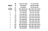
<Corresponding color (printer vector) settings for color conversion output operation>
The printer vector conversion corresponding to color conversion is shown. As an operation, a scanner vector and a printer vector (12 hues (Ry, Yr, Yg, Gy, Gc, Cg, Cb, Bc, Bm, Bm) corresponding to a selected color selected from 8 colors (basic 6 hues + black and white) are used. , Mb, Mr, Rm) + W, K), the scanner vector table is selected and replaced with the printer vector value corresponding to the color set on the operation panel.
色変換に関わるプリンタベクタを以下のように仮定する。
変換される色(変換前設定色)1:Pchf1(Pchf1_r,Pchf1_g,Pchf1_b,Pchf1_k)
変換される色(変換前設定色)2:Pchf2(Pchf2_r,Pchf2_g,Pchf2_b,Pchf2_k)
変換する色(変換後設定色)1:Pcha1(Pcha1_r,Pcha1_g,Pcha1_b,Pcha1_k)
変換する色(変換後設定色)2:Pcha2(Pcha2_r,Pcha2_g,Pcha2_b,Pcha2_k)
Assume the following printer vectors for color conversion:
Color to be converted (set color before conversion) 1: Pchf1 (Pchf1_r, Pchf1_g, Pchf1_b, Pchf1_k)
Color to be converted (pre-conversion setting color) 2: Pchf2 (Pchf2_r, Pchf2_g, Pchf2_b, Pchf2_k)
Color to be converted (set color after conversion) 1: Pcha1 (Pcha1_r, Pcha1_g, Pcha1_b, Pcha1_k)
Color to be converted (set color after conversion) 2: Pcha2 (Pcha2_r, Pcha2_g, Pcha2_b, Pcha2_k)
この場合、変換される色のプリンタベクタは次のような構成となる。
Pchf1(Pcha1_r,Pcha1_g,Pcha1_b,Pcha1_k)
Pchf2(Pcha2_r,Pcha2_g,Pcha2_b,Pcha2_k)
In this case, the printer vector of the color to be converted has the following configuration.
Pchf1 (Pcha1_r, Pcha1_g, Pcha1_b, Pcha1_k)
Pchf2 (Pcha2_r, Pcha2_g, Pcha2_b, Pcha2_k)
例えば、黄を緑に変換する場合、以下のように、黄のプリンタベクタを緑のプリンタベクタに置換することになる。
Yr:(Gyr,Gyg,Gyb,Gyk)
Yg:(Gcr,Gcg,Gcb,Gck)
For example, when converting yellow to green, the yellow printer vector is replaced with the green printer vector as follows.
Yr: (Gyr, Gyg, Gyb, Gyk)
Yg: (Gcr, Gcg, Gcb, Gck)
ただし、通常のプリンタベクタは以下のように設定されているものとする。
黄のプリンタベクタ
Yr:(Yrr,Yrg,Yrb,Yrk)
Yg:(Ygr,Ygg,Ygb,Ygk)
緑のプリンタベクタ:
Gy:(Gyr,Gyg,Gyb,Gyk)
Gc:(Gcr,Gcg,Gcb,Gck)
However, it is assumed that a normal printer vector is set as follows.
Yellow printer vector Yr: (Yrr, Yrg, Yrb, Yrk)
Yg: (Ygr, Ygg, Ygb, Ygk)
Green printer vector:
Gy: (Gyr, Gyg, Gyb, Gyk)
Gc: (Gcr, Gcg, Gcb, Gck)
ここで、追跡パターン色出力予測部260は、色相分割マスキング部230の色補正パラメータを形成する前述のスキャナベクタを入力色空間内の代表色として扱う。
Here, the tracking pattern color
すなわち、追跡パターン色出力予測部260は、対象とする原稿のR、G、B、C、M、Y毎にそれぞれを囲む2色を用いた計12色の色原稿パッチに対応するスキャナγ補正後のRGB値に対する色加工を含む画像出力条件下での出力色と、追跡パターンが付加された同色に対する色加工を含む画像出力条件下での出力色との色差を算出する。そして、追跡パターン色出力予測部260は、算出した色差をパラメータ調整部250に送る。
That is, the tracking pattern color
例えば、前述のシングルカラー出力動作時の白地に対する追跡パターンの影響として算出する色差は、シングルカラー向けの設定色としてプリンタベクタ(Xr’,Xg’,Xb’,Xk’)を用いた場合、色A(統一RGB値)と色B(統一RGB値)との差となる。色Aは、白のスキャナベクタ:W(Wr、Wg、Wb)に対応する以下の対応色(プリンタベクタ)である。
W(Xr’,Xg’,Xb’,Xk’)×[{(Wr−Wr)×sr+(Wg−Wg)×sg+(Wb−Wb)×sb}/(sr+sg+sb)]
For example, the color difference calculated as the influence of the tracking pattern on the white background during the above-described single color output operation is obtained when the printer vector (Xr ′, Xg ′, Xb ′, Xk ′) is used as the set color for single color. This is the difference between A (unified RGB value) and color B (unified RGB value). Color A is the following corresponding color (printer vector) corresponding to the white scanner vector: W (Wr, Wg, Wb).
W (Xr ′, Xg ′, Xb ′, Xk ′) × [{(Wr−Wr) × sr + (Wg−Wg) × sg + (Wb−Wb) × sb} / (sr + sg + sb)]
色Bは、白(Wr、Wg、Wb)に追跡パターン(黄色ドット)を付加した色(Wr’、Wg’、Wb’)に、設定したシングルカラー出力向けに算出したパラメータマスキング係数を用いて色相分割マスキング演算を実行して得られる出力色W(+y)の色である。 The color B is a color (Wr ′, Wg ′, Wb ′) obtained by adding a tracking pattern (yellow dot) to white (Wr, Wg, Wb), using the parameter masking coefficient calculated for the set single color output. This is the color of the output color W (+ y) obtained by executing the hue division masking operation.
白のスキャナベクタ(Wr’、Wg’、Wb’)は、予め求めて代表色としてテーブル化しておき、統一RGB値で示された白地に追跡パターン(黄色ドット)を付加した入力色に対してシングルカラー出力した色と白地との色差を求める際は、前述した統一RGBの定義式から算出してもよい。また、図4の3D−LUT色変換部240がCMYK値を介してCIELAB値を求めてから色差を算出しても構わない。CMYK値からCIELAB値への変換は、予め代表色に対して測色を実行して、3次元テーブル化して補間演算で求めてもよい。また、ニューラルネットワークを用いて予め構築したCMY(K)に対する混色シミュレータを用いて、CIELAB値を推定しても構わない。
The white scanner vectors (Wr ′, Wg ′, Wb ′) are obtained in advance and tabulated as representative colors, and the input color is obtained by adding a tracking pattern (yellow dots) to a white background indicated by a unified RGB value. When obtaining a color difference between a single color output color and a white background, the color difference may be calculated from the above-described unified RGB definition formula. Further, the color difference may be calculated after the 3D-LUT
パラメータ調整部250は、追跡パターン色出力予測部260で求めた白地に追跡パターン(黄色ドット)を付加した入力色に対してシングルカラー出力した色と白地との色差と、操作表示部10で選択された出力アプリ(画像出力デバイス)に応じて設定された許容色差とを比較する。そして、許容色差より色差が大きくなった場合、パラメータ調整部250は、追跡パターン(黄色ドット)を付加した白のスキャナベクタ(Wr’、Wg’、Wb’)のRGB値(スキャナγ補正後)に対して、前述の色相分割マスキング処理を実行した際の色相領域判定される色相領域に対するプリンタベクタの算出式を調整する。
The
具体的には、パラメータ調整部250は、以下に示すY領域に対する感色性を考慮した重み付け係数(sr、sg、sb)を調整する。
Yr(Xr’,Xg’,Xb’,Xk’)×[{(Yrr−Wr)×sr+(Yrg−Wg)×sg+(Yrb−Wb)×sb}/(sr+sg+sb)]
Yg(Xr’,Xg’,Xb’,Xk’)×[{(Ygr−Wr)×sr+(Ygg−Wg)×sg+(Ygb−Wb)×sb}/(sr+sg+sb)]
Specifically, the
Yr (Xr ′, Xg ′, Xb ′, Xk ′) × [{(Yrr−Wr) × sr + (Yrg−Wg) × sg + (Yrb−Wb) × sb} / (sr + sg + sb)]
Yg (Xr ′, Xg ′, Xb ′, Xk ′) × [{(Ygr−Wr) × sr + (Ygg−Wg) × sg + (Ygb−Wb) × sb} / (sr + sg + sb)]
この調整は、重み付け係数(sr、sg、sb)の和に対して、相対的にsbを小さくすることで、白地に追跡パターン(黄色ドット)を付加した入力色のシングルカラー出力色と白地との色差が小さくなり、これが前述の許容色差内に収まるまで実行する。 This adjustment is achieved by reducing the sb relative to the sum of the weighting coefficients (sr, sg, sb), thereby providing a single color output color of the input color in which the tracking pattern (yellow dots) is added to the white background and the white background. This is executed until the color difference becomes smaller and falls within the allowable color difference.
例えば、以下のように感色性に対する重み係数の組み合わせを用意しておいて、前述の色差演算を許容色差内に収まるまで実行する方法を用いることができる。重み付け係数(sr、sg、sb)を調整することで、シングルカラーの設定色(プリンタベクタ:Xr’,Xg’,Xb’,Xk’)に応じた追跡パターンのドットが目立たない色調整が可能となる。 For example, it is possible to use a method of preparing a combination of weighting factors for color sensitivity as described below and executing the above-described color difference calculation until it falls within the allowable color difference. By adjusting the weighting coefficients (sr, sg, sb), it is possible to perform color adjustment that makes the dots of the tracking pattern inconspicuous according to the single color setting color (printer vector: Xr ′, Xg ′, Xb ′, Xk ′). It becomes.
(シングルカラー向け感色性パラメータ(Yr,Yg色相向け))
sr sg sb
パラメータ0:4 6 2
パラメータ1:3 6 1
パラメータ2:3 7 1
パラメータ3:4 8 1
パラメータ4:5 9 1
パラメータ5:6 10 1
(Color sensitivity parameter for single color (for Yr, Yg hue))
sr sg sb
Parameter 0: 4 6 2
Parameter 1: 3 6 1
Parameter 2: 3 7 1
Parameter 3: 4 8 1
Parameter 4: 5 9 1
Parameter 5: 6 10 1
2色カラー出力動作時の白地に対する追跡パターンの影響として算出する色差は、(原稿の黒部分以外に設定された)指定色のプリンタベクタ(Yr,Yg,Yb,Yk)によって決まる。本実施形態の2色カラー出力では、変換前色(スキャナベクタ)のライトネス(明るさ成分)に関係なく、彩度成分を含む色の強さに応じて、指定色の再現濃度を決めている。このため、白地にある追跡パターン(黄色ドット)が青のような暗い色に置き換わると白地との色差が大きくなることがある。 The color difference calculated as the effect of the tracking pattern on the white background during the two-color output operation is determined by the printer vector (Yr, Yg, Yb, Yk) of the designated color (set other than the black part of the document). In the two-color output of this embodiment, the reproduction density of the designated color is determined according to the strength of the color including the saturation component regardless of the lightness (brightness component) of the color before conversion (scanner vector). . For this reason, if a tracking pattern (yellow dots) on a white background is replaced with a dark color such as blue, the color difference from the white background may increase.
そこで、追跡パターン(黄色ドット)を付加した白のスキャナベクタ(Wr’、Wg’、Wb’)のRGB値(スキャナγ補正後)に対して、前述の色相分割マスキング処理を実行した際の色相領域判定される色相領域に対するプリンタベクタの算出式を、以下に示すように対象色のライトネス成分を考慮したものに変更する。そして、以下のように感色性に対する重み係数の組み合わせを用意しておき、パラメータ調整部250により、前述の色差演算を許容色差内に収まるまでプリンタベクタを調整する。
Therefore, the hue when the above-described hue division masking process is executed on the RGB values (after the scanner γ correction) of the white scanner vector (Wr ′, Wg ′, Wb ′) to which the tracking pattern (yellow dot) is added. The printer vector calculation formula for the hue area to be area-determined is changed to one that takes into account the lightness component of the target color as shown below. Then, combinations of weighting factors for color sensitivity are prepared as follows, and the printer vector is adjusted by the
Yr(Yr’,Yg’,Yb’,Yk’)→
Yr(Xr’,Xg’,Xb’,Xk’)×[{(Yrr−Wr)×sr+(Yrg−Wg)×sg+(Yrb−Wb)×sb}/(sr+sg+sb)/1024]
Yg(Yr’,Yg’,Yb’,Yk’)→
Yg(Xr’,Xg’,Xb’,Xk’)×[{(Ygr−Wr)×sr+(Ygg−Wg)×sg+(Ygb−Wb)×sb}/(sr+sg+sb)/1024]
Yr (Yr ′, Yg ′, Yb ′, Yk ′) →
Yr (Xr ′, Xg ′, Xb ′, Xk ′) × [{(Yrr−Wr) × sr + (Yrg−Wg) × sg + (Yrb−Wb) × sb} / (sr + sg + sb) / 1024]
Yg (Yr ′, Yg ′, Yb ′, Yk ′) →
Yg (Xr ′, Xg ′, Xb ′, Xk ′) × [{(Ygr−Wr) × sr + (Ygg−Wg) × sg + (Ygb−Wb) × sb} / (sr + sg + sb) / 1024]
(2色カラー向け感色性パラメータ(Yr,Yg色相向け))
sr sg sb
パラメータ0:2 4 10
パラメータ1:2 4 8
パラメータ2:2 4 6
パラメータ3:2 4 4
パラメータ4:2 4 2
パラメータ5:2 4 1
(Color sensitivity parameter for two color (for Yr, Yg hue))
sr sg sb
Parameter 0: 2 4 10
Parameter 1: 2 4 8
Parameter 2: 2 4 6
Parameter 3: 2 4 4
Parameter 4: 2 4 2
Parameter 5: 2 4 1
色変換出力(Y→赤)動作時の白地に対する追跡パターンの影響についても同様である。すなわち、変換前色(スキャナベクタ)のライトネス(明るさ成分)に関係なく、彩度成分を含む色の強さに応じて、変換色の再現濃度を決めている。このため、白地にある追跡パターン(黄色ドット)が暗い色に置き換わると白地との色差が大きくなることがある。 The same applies to the influence of the tracking pattern on the white background during the color conversion output (Y → red) operation. That is, regardless of the lightness (brightness component) of the color before conversion (scanner vector), the reproduction density of the converted color is determined according to the strength of the color including the saturation component. For this reason, if the tracking pattern (yellow dots) on a white background is replaced with a dark color, the color difference from the white background may increase.
黄を緑に色変換する場合、以下のように、黄のプリンタベクタを緑のプリンタベクタに置換する際、調整パラメータ(A)を16から減少させて変換色の色の強さを抑える。このようにして、パラメータ調整部250は、前述の色差演算を許容色差内に収まるまで、プリンタベクタの算出式を調整する。
Yr:(Gyr,Gyg,Gyb,Gyk)×A/16
Yg:(Gcr,Gcg,Gcb,Gck)×A/16
In the case of converting yellow to green, as described below, when replacing the yellow printer vector with the green printer vector, the adjustment parameter (A) is decreased from 16 to suppress the color strength of the converted color. In this way, the
Yr: (Gyr, Gyg, Gyb, Gyk) × A / 16
Yg: (Gcr, Gcg, Gcb, Gck) × A / 16
ただし、通常のプリンタベクタは以下のように設定されているものとする。
黄のプリンタベクタ:
Yr:(Yrr,Yrg,Yrb,Yrk)
Yg:(Ygr,Ygg,Ygb,Ygk)
緑のプリンタベクタ:
Gy:(Gyr,Gyg,Gyb,Gyk)
Gc:(Gcr,Gcg,Gcb,Gck)
However, it is assumed that a normal printer vector is set as follows.
Yellow printer vector:
Yr: (Yrr, Yrg, Yrb, Yrk)
Yg: (Ygr, Ygg, Ygb, Ygk)
Green printer vector:
Gy: (Gyr, Gyg, Gyb, Gyk)
Gc: (Gcr, Gcg, Gcb, Gck)
次に2色カラー出力動作時の様々な色地に対する追跡パターンの影響として算出する色差および色補正パラメータの調整について説明する。 Next, the adjustment of the color difference and the color correction parameter calculated as the influence of the tracking pattern on various color grounds during the two-color output operation will be described.
図13にも示した無彩色軸上の白および黒点を含めた代表色14点のスキャナベクタ(スキャナγ補正後のRGB値)に対して、追跡パターン色出力予測部260は、追跡パターン(黄色ドット)を付加した色(スキャナγ補正後のRGB値)を抽出する。そして、追跡パターン色出力予測部260は、前述したように、抽出した色を入力色とした場合の2色カラー出力動作における出力色(統一RGB値)を、通常の2色モード向けに色相分割マスキング部230によって設定されたマスキング係数を用いて算出する。追跡パターン色出力予測部260は、算出した出力色(統一RGB値)と、2色モード向けに設定したプリンタベクタ(統一RGB値)との色差を求め、パラメータ調整部250に送る。
For the scanner vector of 14 representative colors including the white and black points on the achromatic color axis shown in FIG. 13 (RGB values after scanner γ correction), the tracking pattern color
ここで使用する各色のスキャナベクタに追跡パターン(黄色ドット)を付加した場合の予測値は、予め求めて代表色としてテーブル化しておき、色差については、前述した統一RGBの定義式から算出してもよい。また、3D−LUT色変換部240でCMYK値を介してCIELAB値を求めてから色差を算出しても構わない。CMYK値からCIELAB値の変換は、予め代表色に対して測色を実行して、3次元テーブル化して補間演算で求めてもよい。また、ニューラルネットワークを用いて予め構築したCMY(K)に対する混色シミュレータを用いて、CIELAB値を推定しても構わない。
Predicted values when tracking patterns (yellow dots) are added to the scanner vectors for each color used here are obtained in advance and tabulated as representative colors, and color differences are calculated from the above-described unified RGB definition formula. Also good. The 3D-LUT
パラメータ調整部250は、追跡パターン色出力予測部260で求めた各色相の代表色(スキャナベクタ)に追跡パターン(黄色ドット)を付加した色に対して、例えば、2色カラー出力した色と、2色カラー出力動作に対する対応色(プリンタベクタ)との色差を算出する。パラメータ調整部250は、算出した色差と、操作表示部10で選択された出力アプリ(画像出力デバイス)に応じて設定された許容色差とを比較する。許容色差より色差が大きくなった場合、パラメータ調整部250は、追跡パターン(黄色ドット)を付加したRGB値(スキャナγ補正後)に近づくようにスキャナベクタを調整する。
The
例えば、図13に示すフルカラー動作時の無彩色軸上の白および黒点を含めた14点のスキャナベクタおよびプリンタベクタを、指定された2色出力動作で、プリンタベクタが以下のように変更された場合を説明する。 For example, the 14-point scanner vector and printer vector including the white and black points on the achromatic color axis at the time of full-color operation shown in FIG. Explain the case.
(原稿の黒部分以外に設定された)指定色1のプリンタベクタ:(Yr,Yg,Yb,Yk)
(原稿の黒部分に設定された)指定色2のプリンタベクタ:(Xr,Xg,Xb,Xk)
Printer vector of designated color 1 (set other than the black part of the document): (Yr, Yg, Yb, Yk)
Printer vector of designated color 2 (set to the black part of the document): (Xr, Xg, Xb, Xk)
(無彩色)
W(Xr’,Xg’,Xb’,Xk’)×{(Wr−Wr)×sr+(Wg−Wg)×sg+(Wb−Wb)×sb/(sr+sg+sb)/1024}
K(Xr’,Xg’,Xb’,Xk’)×{(Kr−Wr)×sr+(Kg−Wg)×sg+(Kb−Wb)×sb/(sr+sg+sb)/1024}
(有彩色)
Rm(Yr’,Yg’,Yb’,Yk’)
Ry(Yr’,Yg’,Yb’,Yk’)
Yr(Yr’,Yg’,Yb’,Yk’)
Yg(Yr’,Yg’,Yb’,Yk’)
Gy(Yr’,Yg’,Yb’,Yk’)
Gc(Yr’,Yg’,Yb’,Yk’)
Cg(Yr’,Yg’,Yb’,Yk’)
Cb(Yr’,Yg’,Yb’,Yk’)
Bc(Yr’,Yg’,Yb’,Yk’)
Bm(Yr’,Yg’,Yb’,Yk’)
Mb(Yr’,Yg’,Yb’,Yk’)
Mr(Yr’,Yg’,Yb’,Yk’)
(non-colored)
W (Xr ′, Xg ′, Xb ′, Xk ′) × {(Wr−Wr) × sr + (Wg−Wg) × sg + (Wb−Wb) × sb / (sr + sg + sb) / 1024}
K (Xr ′, Xg ′, Xb ′, Xk ′) × {(Kr−Wr) × sr + (Kg−Wg) × sg + (Kb−Wb) × sb / (sr + sg + sb) / 1024}
(Chromatic color)
Rm (Yr ′, Yg ′, Yb ′, Yk ′)
Ry (Yr ′, Yg ′, Yb ′, Yk ′)
Yr (Yr ′, Yg ′, Yb ′, Yk ′)
Yg (Yr ′, Yg ′, Yb ′, Yk ′)
Gy (Yr ′, Yg ′, Yb ′, Yk ′)
Gc (Yr ′, Yg ′, Yb ′, Yk ′)
Cg (Yr ′, Yg ′, Yb ′, Yk ′)
Cb (Yr ′, Yg ′, Yb ′, Yk ′)
Bc (Yr ′, Yg ′, Yb ′, Yk ′)
Bm (Yr ′, Yg ′, Yb ′, Yk ′)
Mb (Yr ′, Yg ′, Yb ′, Yk ′)
Mr (Yr ′, Yg ′, Yb ′, Yk ′)
前述した色差評価で、例えば、Cg色相だけ許容色差を超えた場合、すなわち、指定された2色モード出力時のプリンタベクタCg(Yr’,Yg’,Yb’,Yk’)と、スキャナベクタCg_s(Cgr,Cgg,Cgb)に追跡パターン(黄色ドット)を付加した色Cg_s’(Cgr’,Cgg’,Cgb’)に対する色相分割マスキング演算後の色Cg”(Yr”,Yg”,Yb”,Yk”)との色差が許容色差より大きくなった際には、以下のように、Cg色相のスキャナベクタの各成分の調整パラメータ(A)を16から減少させる。パラメータ調整部250は、追跡パターン(黄色ドット)を付加したRGB値(スキャナγ補正後)に近づき、前述の色差が許容色差内に収まるまで、スキャナベクタを調整して、前述のマスキング係数を算出する。パラメータ調整部250は、算出したマスキング係数を、色相分割マスキング部230の色補正パラメータとして設定する。
Cgr”=Cgr’+(Cgr−Cgr’)×A/16
Cgg”=Cgg’+(Cgg−Cgg’)×A/16
Cgb”=Cgb’+(Cgb−Cgb’)×A/16
In the above-described color difference evaluation, for example, when the allowable color difference is exceeded by Cg hue, that is, the printer vector Cg (Yr ′, Yg ′, Yb ′, Yk ′) at the time of designated two-color mode output and the scanner vector Cg_s. Colors Cg ″ (Yr ″, Yg ″, Yb ″, and Cg_s ′ (Cgr ′, Cgg ′, Cgb ′) obtained by adding a tracking pattern (yellow dots) to (Cgr, Cgg, Cgb) after hue division masking calculation. When the color difference from Yk ″) is larger than the allowable color difference, the adjustment parameter (A) of each component of the Cg hue scanner vector is decreased from 16 as follows. Adjust the scanner vector until the color value approaches the RGB value (after scanner γ correction) with (yellow dot) added, and the color difference is within the allowable color difference, and calculate the masking coefficient. To.
Cgr ″ = Cgr ′ + (Cgr−Cgr ′) × A / 16
Cgg ″ = Cgg ′ + (Cgg−Cgg ′) × A / 16
Cgb ″ = Cgb ′ + (Cgb−Cgb ′) × A / 16
本実施形態では、図1の画像処理部2を介して統一RGB画像データに変換してメモリ7に蓄積した統一RGB画像データを利用して、カラー複写機出力画像に特有な追跡パターンを検出する。これは、紙幣や有価証券などの複写の悪用を防止するためのものである。すなわち、紙幣や有価証券などを複写したときに、何らかのパターンがプリントされるように、対策が講じられている。このような追跡パターンは、白地上にも孤立して存在していること、イエローでプリントされていることを利用し、局所的な画像処理によって高精度に検出する。
In the present embodiment, a tracking pattern specific to the color copier output image is detected using the unified RGB image data converted into the unified RGB image data and stored in the
(ジェネレーション原稿判定)
以下に、入力原稿がジェネレーション原稿であるかを検出するジェネレーション原稿判定部の構成例について説明する。図14は、ジェネレーション原稿判定部300の構成例を示すブロック図である。
(Generation manuscript judgment)
A configuration example of a generation document determination unit that detects whether an input document is a generation document will be described below. FIG. 14 is a block diagram illustrating a configuration example of the generation
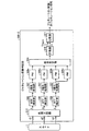
ジェネレーション原稿判定部300は、MTF補正部306と、2値化処理部307と、パターンマッチング回路(以下、PMという)308a、308b、308cと、総合判定部309と、計数器310と、比較器311と、を備えている。
The generation
ジェネレーション原稿であるか否かを判定するため、本実施形態では、カラー複写機出力画像には必ず印字されている追跡パターンに注目し、追跡パターンをパターンマッチングの利用により検出する。 In order to determine whether or not the document is a generation document, in this embodiment, attention is paid to the trace pattern that is always printed on the color copier output image, and the trace pattern is detected by using pattern matching.
一般に追跡パターンは400dpiプリンタで2画素×2画素や1画素×3画素の程度の大きさで、イエロートナーで印字される。従って、イエローの補色であるb信号に対し、後述する図15(b)に示すようなパターンマッチングを行えば追跡パターンが検出できる。 Generally, the tracking pattern is printed with yellow toner with a size of about 2 pixels × 2 pixels or 1 pixel × 3 pixels by a 400 dpi printer. Therefore, a tracking pattern can be detected by performing pattern matching as shown in FIG. 15B described later on the b signal which is a complementary color of yellow.
しかし、次のような問題が生じる。
(1)印刷原稿は数多くの網点ドットから形成されている。図15(b)のパターンでは、網点ドットを追跡パターンとして誤検出し、その結果として印刷原稿をジェネレーション原稿と誤判定することになる。一般の印刷原稿ではハイライト部でもある程度はドットが密集している。
(2)上記のように追跡パターンを白地上の孤立ドットに限定しても、ゴミ(ノイズ)が原稿に載ることが多い。ノイズであるため、このようなゴミはイエローである可能性は少なく、多くは無彩色であるので、3信号を使って追跡パターンを、特にイエローの領域に限定している。
However, the following problems arise.
(1) A printed document is formed from a large number of halftone dots. In the pattern of FIG. 15B, halftone dots are erroneously detected as a tracking pattern, and as a result, the printed document is erroneously determined as a generation document. In a general printed document, dots are concentrated to some extent even in a highlight portion.
(2) Even if the tracking pattern is limited to isolated dots on the white ground as described above, dust (noise) often appears on the original. Because of the noise, there is little possibility that such dust is yellow, and many are achromatic colors. Therefore, the tracking pattern is limited to the yellow area using three signals.
スキャナ1は、図1で説明したように、CCDカメラなどの光電変換素子を有し、原稿を読み取って、赤、緑、青の3色分解信号(アナログ)を得て、これら3信号に対して、A/D変換を行い、RGBのデジタル信号(各8ビット)を出力する。ここでは、スキャナ1の解像度は400dpiとする。出力信号値は、紙白が255で、黒が0である。
As described with reference to FIG. 1, the
MTF補正部306は、後段の2値化処理の前処理として、RGB信号それぞれに対して、MTF補正フィルタを施す。図16は、MTF補正フィルタの係数の一例を示す図である。
The
2値化処理部307は、MTF補正後の信号に対して2値化処理を行う。注目画素レベルをXとすると、2値化処理部307は、Xが所定の閾値thより小さいときに注目画素を黒画素とし、Xが閾値th以上のときに注目画素を白画素とする。
The
PM308aは、r信号およびg信号用パターンによるパターンマッチングを行う。図15(a)は、r信号およびg信号用パターンの一例を示す図である。PM308aにより、rやgの補色であるシアン色やマゼンタ色が注目画素近傍に存在しない領域、すなわちイエロー領域を検出することができる。
The
PM308bは、b信号用パターンによるパターンマッチングを行う。図15(b)は、b信号用パターンの一例を示す図である。前述したように、追跡パターンは大きくても400dpiで3画素×3画素以下であるため、図15(b)に示すようなパターンによりマッチングを行う。ただし、このパターンのみではイエローの網点ドットにマッチングしてしまうので、次に説明する白地に囲まれた領域であるか否かを判定するPM308cを準備する必要がある。
The
PM308cは、注目画素が白地に囲まれて、真に孤立した領域であるか否かを判定するためのb信号用パターンによるパターンマッチングを行う。図15(c)は、この場合のb信号用パターンの一例を示す図である。印刷の網点ドットはハイライト領域であるが、図15(c)に示したようなパターンにマッチングするような網点ドットは存在しない。すなわち、網点ドットはもう少し密集している。
The
なお、説明を簡単にするため、b信号を利用したが、白地に囲まれた領域をより正確に検出する場合には、MTF補正後のmin(r,g,b)を2値化した信号を用いて本パターンマッチングを行ってもよい。 In order to simplify the explanation, the b signal is used. However, in the case where a region surrounded by a white background is more accurately detected, a signal obtained by binarizing min (r, g, b) after MTF correction is used. This pattern matching may be performed using.
総合判定部309は、4つのパターンマッチング回路(2つのPM308a、PM308b、および、PM308c)からの出力が全てオンのとき、すなわち全てマッチングしたとき、注目画素を追跡パターン画素として判定する。
When the outputs from the four pattern matching circuits (two
計数器310は、原稿全面にわたって、前述した追跡パターンの画素数を計数する。
The
比較器311は、前述した追跡パターン画素の計数値(V)と所定の閾値(THgen)とを比較し、V>THgenであれば、原稿がジェネレーション原稿であるという信号を出力する。
The
以上、説明を簡単にするために、ジェネレーション原稿判定に用いる信号としてRGB信号を利用したが、より精度を向上させるためには、RGB信号に対しジェネレーション用の色補正を実行してcmy信号を得て、このcmy信号で同様の判定を行うことも有効である。図17は、このように構成したジェネレーション原稿判定部300−2の構成例を示すブロック図である。図17は、RGB信号をcmy信号に補正する色補正回路12をさらに備える点が図14のジェネレーション原稿判定部300と異なっている。
For the sake of simplicity, the RGB signal is used as a signal used for generation document determination. However, in order to improve the accuracy, the color correction for generation is performed on the RGB signal to obtain a cmy signal. Thus, it is also effective to make a similar determination using this cmy signal. FIG. 17 is a block diagram illustrating a configuration example of the generation document determination unit 300-2 configured as described above. FIG. 17 is different from the generation
また、実際のスキャナ1からの出力にはノイズを含むこともあり、スキャナ1から出力された信号にノイズ除去のために平滑化フィルタを施すことも有効である。
Further, the actual output from the
(ジェネレーション原稿判定を利用した画像再生装置)
ここでは、前述した図14のジェネレーション原稿判定部300を利用して、画像を再生する装置(以下、画像処理装置400という)の例について説明する。
(Image playback device using generation manuscript judgment)
Here, an example of an apparatus that reproduces an image using the generation
図18は、本実施形態の画像処理装置400の構成例を示すブロック図である。図18に示すように、画像処理装置400は、スキャナ1と、Log変換部401と、色補正回路402と、プロッタ9と、ジェネレーション原稿判定部300と、色補正計数格納部403と、を備えている。
FIG. 18 is a block diagram illustrating a configuration example of the
以下、説明を簡単にするため、準備する色補正手段としては、網点写真(印刷)用とジェネレーション原稿用の2種類を持つことにする。特許文献2に記載された技術を利用して、さらに銀塩写真(印画紙)用の色補正手段、および、それらの混在用の色補正手段などを準備してもよい。これにより、広範囲の原稿に対しての色の忠実性を保証できる。
Hereinafter, in order to simplify the explanation, the color correction means to be prepared has two types, one for halftone photographs (printing) and one for generation documents. By using the technique described in
Log変換部401は、概ね反射率リニアな信号であるスキャナ1の出力信号を、色補正処理により、有利な濃度信号(RGB信号)に変換する。
The
色補正回路402は、次のような線形一次式で色補正を行う。すなわち、R,G,BをLog変換後の信号(各8ビット)とし、Y,M,Cをプリンタ駆動信号とし、a0−a3、b0−b3、c0−c3を色補正係数群とすると、色補正回路402による色補正は、以下に示す式によって表される。
The
C=a0+a1×R+a2×G+a3×B
M=b0+b1×R+b2×G+b3×B
Y=c0+c1×R+c2×G+c3×B
C = a0 + a1 × R + a2 × G + a3 × B
M = b0 + b1 × R + b2 × G + b3 × B
Y = c0 + c1 × R + c2 × G + c3 × B
プロッタ9は、ここでは、シアン、マゼンタ、イエローの3色で画像を作成するプリンタとする。プロッタ9は、駆動信号(C,M,Y)を受取り、画像を作成する。なお、ブラックを加えた4色再生のときは、例えばmin(C,M,Y)でブラック信号を作成し、その分をC,M,Yから引くいわゆるUCR処理によって駆動信号を作り、プリントアウトすればよい。
Here, the
ジェネレーション原稿判定部300は、図14で説明したように、ジェネレーション原稿(電子写真式プリンタ原稿)とそれ以外とを判定する。すなわち、ジェネレーション原稿判定部300は、印刷原稿を識別し、その結果を出力する。
As described with reference to FIG. 14, the generation
ジェネレーション原稿判定部300は、例えば図1の画像処理部2に備えられる。そして、ジェネレーション原稿判定部300によりジェネレーション原稿であると判定されたときのみ、図1の画像処理部4が、前述した画像出力条件の調整を実行して算出した色補正係数を用い、色補正処理を行う。
The generation
本実施形態では、前述した統一RGBから色差を求める際、三刺激値(CIEXYZ)に色変換された画像信号を介して、観察条件下における色の見えを予測する知覚量に変換しても構わない。 In the present embodiment, when obtaining the color difference from the above-described unified RGB, the color difference may be converted into a perceptual amount for predicting the appearance of the color under the observation condition via the image signal color-converted to the tristimulus value (CIEXYZ). Absent.
前述したように、対象色は読み取り値から色変換された統一RGBになっている。このため、統一RGBをsRGBと仮定した場合、三刺激値(CIEXYZ)への色変換は以下の(5)式および(6)式のようになる。
r=(R/1023)2.2、
g=(G/1023)2.2、
b=(B/1023)2.2 ・・・(5)
X=0.4124×r+0.3576×g+0.1805×b、
Y=0.2126×r+0.7152×g+0.0722×b、
Z=0.0193×r+0.1192×g+0.9505×b ・・・(6)
As described above, the target color is unified RGB obtained by color conversion from the read value. For this reason, when the unified RGB is assumed to be sRGB, the color conversion to the tristimulus value (CIEXYZ) is expressed by the following equations (5) and (6).
r = (R / 1023) 2.2 ,
g = (G / 1023) 2.2 ,
b = (B / 1023) 2.2 (5)
X = 0.4124 × r + 0.3576 × g + 0.1805 × b,
Y = 0.2126 × r + 0.7152 × g + 0.0722 × b,
Z = 0.0193 × r + 0.1192 × g + 0.9505 × b (6)
ここで、変換された記録紙の地肌(白色)の三刺激値(CIEXYZ)を、CIEで勧告されたカラーアピアランスモデル(CIECAM)で定義されている参照白色の三刺激値(Xw、Yw、Zw)として設定し、以下の処理を実行して知覚量(JCH)に変換する。 Here, the converted tristimulus values (CIEXYZ) of the background (white) of the recording paper are used as the reference white tristimulus values (Xw, Yw, Zw) defined by the color appearance model (CIECAM) recommended by the CIE. ), And the following processing is executed to convert it into a perceptual amount (JCH).
なお、本実施形態では、
試験色:X、Y、Z→スキャナ1から入力された画像信号の三刺激値
参照白色:Xw、Yw、Zw→記録紙の地肌(白色)の三刺激値(読み取り値から算出)
として演算を実行する。
Test color: X, Y, Z → Tristimulus value of image signal input from
The operation is executed as follows.
Rc=(D×(1.0/Rw)+1−D)×R、
Gc=(D×(1.0/Gw)+1−D)×G、
if(B<0)
Bc=(D×(1.0/pow(Bw,p))+1−D)×fabs(pow(B,p))×(−1.0)
else
Bc=(D×(1.0/pow(Bw,p))+1−D)×pow(B,p)
・・・(10)
Rcw=(D×(1.0/Rw)+1−D)×Rw、
Gcw=(D×(1.0/Gw)+1−D)×Gw、
Bcw=(D×(1.0/pow(Bw,p))+1−D)×pow(fabs(Bw),p) ・・・(11)
ただし、
p=pow((Bw/1.0),0.0834)・・・(12)
D=F−F/(1+2×pow(La,1/4)+La×La/300)
・・・(13)
Rc = (D × (1.0 / Rw) + 1−D) × R,
Gc = (D × (1.0 / Gw) + 1−D) × G,
if (B <0)
Bc = (D × (1.0 / pow (Bw, p)) + 1−D) × fabs (pow (B, p)) × (−1.0)
else
Bc = (D × (1.0 / pow (Bw, p)) + 1−D) × pow (B, p)
... (10)
Rcw = (D × (1.0 / Rw) + 1−D) × Rw,
Gcw = (D × (1.0 / Gw) + 1−D) × Gw,
Bcw = (D × (1.0 / pow (Bw, p)) + 1−D) × pow (fabs (Bw), p) (11)
However,
p = pow ((Bw / 1.0), 0.0834) (12)
D = F−F / (1 + 2 × pow (La, 1/4) + La × La / 300)
... (13)
なお、Laは順応視野の輝度であり、Fは順応の程度を表す係数である。 Note that La is the luminance of the adaptation field of view, and F is a coefficient representing the degree of adaptation.
ここで定義したDファクター(順応係数)については、基本的に、この定義式に基づいて算出される。画像出力時に、操作表示部10から出力画像の観察条件をパラメータとして設定された場合は、Dファクター(順応係数)に反映させる。
The D factor (adaptation coefficient) defined here is basically calculated based on this defining formula. When an output image viewing condition is set as a parameter from the
Rda=(40×pow((Fl×Rd/100),0.73))/(pow((Fl×Rd/100),0.73)+2)+1
Gda=(40×pow((Fl×Gd/100),0.73))/(pow((Fl×Gd/100),0.73)+2)+1
Bda=(40×pow((Fl×Bd/100),0.73))/(pow((Fl×Bd/100),0.73)+2)+1 ・・・(16)
Rdaw=(40×pow((Fl×Rdw/100),0.73))/(pow((Fl×Rdw/100),0.73)+2)+1
Gdaw=(40×pow((Fl×Gdw/100),0.73))/(pow((Fl×Gdw/100),0.73)+2)+1
Bdaw=(40×pow((Fl×Bdw/100),0.73))/(pow((Fl×Bdw/100),0.73)+2)+1 ・・・(17)
Rda = (40 × pow ((F1 × Rd / 100), 0.73)) / (pow ((F1 × Rd / 100), 0.73) +2) +1
Gda = (40 × pow ((F1 × Gd / 100), 0.73)) / (pow ((F1 × Gd / 100), 0.73) +2) +1
Bda = (40 × pow ((F1 × Bd / 100), 0.73)) / (pow ((F1 × Bd / 100), 0.73) +2) +1 (16)
Rdaw = (40 × pow ((F1 × Rdw / 100), 0.73)) / (pow ((F1 × Rdw / 100), 0.73) +2) +1
Gdaw = (40 × pow ((F1 × Gdw / 100), 0.73)) / (pow ((F1 × Gdw / 100), 0.73) +2) +1
Bdaw = (40 × pow ((F1 × Bdw / 100), 0.73)) / (pow ((F1 × Bdw / 100), 0.73) +2) +1 (17)
k=1/(5×La+1) ・・・(19)
Fl=0.2×pow(k,4)×(5×La)+0.1×(1−pow(k,4))×(1−pow(k,4))×pow(5×La,1/3) ・・・(20)
n=Yb/Yw ・・・(21)
Nbb=0.725×pow(1/n,0.2) ・・・(22)
Ncb=Nbb ・・・(23)
z=1+Fll×pow(n,0.5) ・・・(24)
k = 1 / (5 × La + 1) (19)
Fl = 0.2 × pow (k, 4) × (5 × La) + 0.1 × (1-pow (k, 4)) × (1-pow (k, 4)) × pow (5 × La, 1/3) (20)
n = Yb / Yw (21)
Nbb = 0.725 × pow (1 / n, 0.2) (22)
Ncb = Nbb (23)
z = 1 + Fll × pow (n, 0.5) (24)
なお、Ybは背景の輝度率、Flは順応輝度に応じた係数、Fllは明度コントラスト係数、nは背景が刺激の見えに影響を及ぼす程度を表す係数である。
Ca=Rda−12.0×Gda/11.0+Bda/11.0、
Cb=(1/9)×(Rda+Gda−2×Bda)、
h=(180/M_PI)×atan2(b,a)、
if(h<0) h=360−fabs(h) ・・・(25)
e=e1+(e2−e1)×(h−h1)/(h2−h1) ・・・(26)
H=h1+100×(h−h1)/e1/((h−h1)/e1+(h2−h)/e2) ・・・(27)
Yb is a background luminance rate, Fl is a coefficient corresponding to adaptation brightness, Fll is a lightness contrast coefficient, and n is a coefficient representing the degree to which the background affects the appearance of the stimulus.
Ca = Rda-12.0 × Gda / 11.0 + Bda / 11.0,
Cb = (1/9) × (Rda + Gda−2 × Bda),
h = (180 / M_PI) × atan2 (b, a),
if (h <0) h = 360−fabs (h) (25)
e = e1 + (e2−e1) × (h−h1) / (h2−h1) (26)
H = h1 + 100 × (h−h1) / e1 / ((h−h1) / e1 + (h2−h) / e2) (27)
ただし、
if(h<=20.14){
e1=0.8565
e2=0.8
h1=0.0
h2=20.14
}
else if(h<=90.0){
e1=0.8
e2=0.7
h1=20.14
h2=90.0
}
else if(h<=164.25){
e1=0.7
e2=1.0
h1=90.0
h2=164.25
}
else if(h<=237.53){
e1=1.0
e2=1.2
h1=164.25
h2=237.53
}
else{
e1=1.2
e2=0.8565
h1=237.53
h2=360.0
} ・・・(28)
However,
if (h <= 20.14) {
e1 = 0.8565
e2 = 0.8
h1 = 0.0
h2 = 20.14
}
else if (h <= 90.0) {
e1 = 0.8
e2 = 0.7
h1 = 20.14
h2 = 90.0
}
else if (h <= 164.25) {
e1 = 0.7
e2 = 1.0
h1 = 90.0
h2 = 164.25
}
else if (h <= 237.53) {
e1 = 1.0
e2 = 1.2
h1 = 164.25
h2 = 237.53
}
else {
e1 = 1.2
e2 = 0.8565
h1 = 237.53
h2 = 360.0
} (28)
A=(2×Rda+Gda+(1/20)×Bda−2.05)×Nbb ・・・(29)
Aw=(2×Rdaw+Gdaw+(1/20)×Bdaw−2.05)×Nbb ・・・(30)
J=100×pow(A/Aw,c×z) ・・・(31)
Q=(1.24/c)×pow((J/100),0.67)×pow((Aw+3),0.9) ・・・(32)
s=(50×pow((a×a+b×b),0.5)×100×e×(10/13)×Nc×Ncb)/(Rda+Gda+(21/20)×Bda)・・・(33)
C=2.44×pow(s,0.69)×pow((J/100),0.67×n)×(1.64−pow(0.29,n)) ・・・(34)
M=C×pow(Fl,0.15) ・・・(35)
A = (2 × Rda + Gda + (1/20) × Bda−2.05) × Nbb (29)
Aw = (2 × Rdaw + Gdaw + (1/20) × Bdaw−2.05) × Nbb (30)
J = 100 × pow (A / Aw, c × z) (31)
Q = (1.24 / c) × pow ((J / 100), 0.67) × pow ((Aw + 3), 0.9) (32)
s = (50 × pow ((a × a + b × b), 0.5) × 100 × e × (10/13) × Nc × Ncb) / (Rda + Gda + (21/20) × Bda) (33 )
C = 2.44 × pow (s, 0.69) × pow ((J / 100), 0.67 × n) × (1.64-pow (0.29, n)) (34)
M = C × pow (F1, 0.15) (35)
ここで、cは周囲の影響の大きさに関する係数、Ncはクロマチックインダクション係数、Aは無彩色応答、Awは白色に対する無彩色応答、Jは明度、Qはブライトネス、sは彩度、Cはクロマ、Mはカラフルネスを表す。 Here, c is a coefficient related to the magnitude of the influence of the surroundings, Nc is a chromatic induction coefficient, A is an achromatic response, Aw is an achromatic response to white, J is lightness, Q is brightness, s is saturation, and C is chroma. , M represents colorfulness.
本実施形態における各種パラメータは、実際にハードコピーを観察する環境に対応した観察条件を、オペレータにより操作表示部10から設定される。特に設定されない場合は、統一RGB(sRGB)の定義に従い、以下のように設定される。
Various parameters in the present embodiment are set by the operator from the
(XtYtZt→JtCtHt)
順応視野の輝度:La=4(cd/m2)
順応の程度を表す係数:F=1.0(Average)
背景の輝度率:Yb=20
明度コントラスト係数:Fll=1.0(Average)
周囲の影響の大きさに関する係数:c=0.69(Average)
クロマチックインダクション係数:Nc=1.0(Average)
(XtYtZt → JtCtHt)
Brightness of adaptation field of view: La = 4 (cd / m 2 )
Coefficient representing the degree of adaptation: F = 1.0 (Average)
Background luminance ratio: Yb = 20
Lightness contrast coefficient: Fll = 1.0 (Average)
Coefficient for magnitude of influence of surroundings: c = 0.69 (Average)
Chromatic induction coefficient: Nc = 1.0 (Average)
ここで求めたカラーアピアランスモデルに基づく知覚量(JCH)に色変換された画像データのユークリッド距離が色補正パラメータの条件となる色差となる。 The Euclidean distance of the image data color-converted to the perceptual amount (JCH) based on the color appearance model obtained here is a color difference that is a condition for the color correction parameter.
以上のように、本実施形態によれば、設定された画像出力条件下の通常の出力色と、追跡パターンが付加された入力色に対する出力色との色差が許容色差以下になるように、入力色を出力色に色補正するときに用いるパラメータを調整する。これにより、いかなる色加工を含む画像出力条件の設定でコピーしても、入力画像の特性に依存することなく、本来の色加工を含む画像出力条件に近い色再現を実現し、追跡パターンのドットが目立たない画像出力を実現できる。また、追跡パターン検出精度が低い画像入力条件で、いかなる色加工を含む画像出力条件の設定でコピーしても、一般原稿に対して本来の色加工を含む画像出力条件に忠実な色再現を実現できる。 As described above, according to this embodiment, the input color is set so that the color difference between the normal output color under the set image output condition and the output color with respect to the input color to which the tracking pattern is added is equal to or less than the allowable color difference. The parameter used when the color is corrected to the output color is adjusted. This makes it possible to reproduce colors close to the image output conditions including the original color processing without depending on the characteristics of the input image, regardless of the characteristics of the input image, regardless of the image output condition settings including the color processing. Can realize image output that is inconspicuous. In addition, even if the image input conditions with low tracking pattern detection accuracy are copied with the image output conditions including any color processing, color reproduction faithful to the image output conditions including the original color processing is realized for general documents. it can.
また、入力画像内の色地上に追跡パターンが打たれていても、追跡パターンの影響を受けない画像領域に対して本来の色加工を含む画像出力条件に忠実な色再現を実現し、追跡パターンの影響を受ける画像領域に対してのみ、本来の色加工を含む画像出力条件に近く追跡パターンのドットが目立たない画像出力を実現できる。 In addition, even if a tracking pattern is struck on the color ground in the input image, color reproduction faithful to the image output conditions including the original color processing is realized for the image area that is not affected by the tracking pattern. Only for the image area affected by the above, it is possible to realize an image output in which the dots of the tracking pattern are inconspicuous, close to the image output conditions including the original color processing.
また、白地上に追跡パターンが打たれている入力原稿に対して、いかなる色加工を含む画像出力条件の設定でコピーしても、本来の色加工を含む画像出力条件に近い色再現を実現し、追跡パターンのドットが目立たない画像出力を実現できる。 In addition, even if an input document with a tracking pattern on a white ground is copied with image output conditions including any color processing, color reproduction close to the original image output conditions including color processing is achieved. Thus, it is possible to realize an image output in which the dots of the tracking pattern are not conspicuous.
また、いかなる色加工を含む画像出力条件の設定でコピーしても、実際の観察環境下で、分光特性に関する情報を使うことなく、比較的容易に、本来の色加工を含む画像出力条件に近い色再現を実現し、追跡パターンのドットが目立たない画像出力を実現できる。 Moreover, even if the image output conditions including any color processing are set, it is relatively easy to approximate the image output conditions including the original color processing without using information on the spectral characteristics in the actual observation environment. Color reproduction can be realized, and image output in which the dots of the tracking pattern are not conspicuous can be realized.
なお、本実施形態の画像処理装置で実行されるプログラムは、ROM等に予め組み込まれて提供される。 Note that the program executed by the image processing apparatus of the present embodiment is provided by being incorporated in advance in a ROM or the like.
本実施形態の画像処理装置で実行されるプログラムは、インストール可能な形式又は実行可能な形式のファイルでCD−ROM、フレキシブルディスク(FD)、CD−R、DVD(Digital Versatile Disk)等のコンピュータで読み取り可能な記録媒体に記録してコンピュータ・プログラム・プロダクトとして提供するように構成してもよい。 The program executed in the image processing apparatus of the present embodiment is a file in an installable format or an executable format, and is a computer such as a CD-ROM, a flexible disk (FD), a CD-R, or a DVD (Digital Versatile Disk). The program may be recorded on a readable recording medium and provided as a computer program product.
さらに、本実施形態の画像処理装置で実行されるプログラムを、インターネット等のネットワークに接続されたコンピュータ上に格納し、ネットワーク経由でダウンロードさせることにより提供するように構成しても良い。また、本実施形態の画像処理装置で実行されるプログラムをインターネット等のネットワーク経由で提供または配布するように構成しても良い。 Furthermore, the program executed by the image processing apparatus of the present embodiment may be provided by being stored on a computer connected to a network such as the Internet and downloaded via the network. The program executed by the image processing apparatus according to the present embodiment may be configured to be provided or distributed via a network such as the Internet.
本実施形態の画像処理装置で実行されるプログラムは、上述した各部(スキャナγ補正部、色調整部、色相分割マスキング部、3D−LUT色変換部、パラメータ調整部、追跡パターン色出力予測部等)を含むモジュール構成となっており、実際のハードウェアとしてはCPU(プロセッサ)が上記ROMからプログラムを読み出して実行することにより上記各部が主記憶装置上にロードされ、上記各部が主記憶装置上に生成されるようになっている。 The program executed by the image processing apparatus of the present embodiment includes the above-described units (scanner γ correction unit, color adjustment unit, hue division masking unit, 3D-LUT color conversion unit, parameter adjustment unit, tracking pattern color output prediction unit, etc. ), And as actual hardware, the CPU (processor) reads the program from the ROM and executes the program, so that the respective units are loaded onto the main storage device, and the respective units are installed on the main storage device. To be generated.
1 スキャナ
9 プロッタ
10 操作表示部
200 色変換処理部
210 スキャナγ補正部
220 色調整部
230 色相分割マスキング部
240 3D−LUT色変換部
250 パラメータ調整部
260 追跡パターン色出力予測部
DESCRIPTION OF
Claims (8)
追跡パターンが付加されない入力色に対する前記画像出力条件下の第1出力色と、追跡パターンが付加された入力色に対する前記画像出力条件下の第2出力色との色差を算出する算出部と、
前記色差に応じて、前記色補正で用いる色補正パラメータを調整する調整部と、
調整された前記色補正パラメータにより前記入力画像データを補正した出力画像データを生成する補正部と、
を備えることを特徴とする画像処理装置。 A receiving unit for receiving an image output condition including a condition for color correction for input image data;
A calculation unit that calculates a color difference between the first output color under the image output condition for the input color to which no tracking pattern is added and the second output color under the image output condition for the input color to which the tracking pattern is added;
An adjustment unit for adjusting a color correction parameter used in the color correction according to the color difference;
A correction unit that generates output image data obtained by correcting the input image data using the adjusted color correction parameter;
An image processing apparatus comprising:
を特徴とする請求項1に記載の画像処理装置。 The adjusting unit adjusts the color correction parameter until the color difference is within a predetermined allowable color difference;
The image processing apparatus according to claim 1.
前記調整部は、前記追跡パターンが検出された場合に、前記色補正パラメータを調整すること、
を特徴とする請求項1に記載の画像処理装置。 A detection unit for detecting a tracking pattern from the input image data;
The adjusting unit adjusts the color correction parameter when the tracking pattern is detected;
The image processing apparatus according to claim 1.
を特徴とする請求項1に記載の画像処理装置。 The adjusting unit adjusts the input color until the color difference is within a predetermined allowable color difference, and calculates the color correction parameter based on the adjusted input color;
The image processing apparatus according to claim 1.
を特徴とする請求項1に記載の画像処理装置。 The color correction parameter is a parameter for adjusting the color sensitivity of the yellow hue to the input color;
The image processing apparatus according to claim 1.
前記算出部は、追跡パターンが付加されない入力色に対する前記観察条件下かつ前記画像出力条件下の前記第1出力色と、追跡パターンが付加された入力色に対する前記観察条件下かつ前記画像出力条件下の前記第2出力色との色差を算出すること、
を特徴とする請求項1に記載の画像処理装置。 The reception unit further receives an observation condition of the output image data,
The calculation unit includes the first output color under the observation condition and the image output condition for an input color to which no tracking pattern is added, and the observation condition and the image output condition for an input color to which a tracking pattern is added. Calculating a color difference from the second output color of
The image processing apparatus according to claim 1.
追跡パターンが付加されない入力色に対する前記画像出力条件下の第1出力色と、追跡パターンが付加された入力色に対する前記画像出力条件下の第2出力色との色差を算出する算出ステップと、
前記色差に応じて、前記色補正で用いる色補正パラメータを調整する調整ステップと、
調整された前記色補正パラメータにより前記入力画像データを補正した出力画像データを生成する補正ステップと、
を含むことを特徴とする画像処理方法。 An accepting step for accepting an image output condition including a condition for color correction for input image data;
A calculation step of calculating a color difference between the first output color under the image output condition for the input color to which no tracking pattern is added and the second output color under the image output condition for the input color to which the tracking pattern is added;
An adjustment step of adjusting a color correction parameter used in the color correction according to the color difference;
A correction step of generating output image data obtained by correcting the input image data with the adjusted color correction parameter;
An image processing method comprising:
入力画像データに対する色補正の条件を含む画像出力条件を受け付ける受付部と、
追跡パターンが付加されない入力色に対する前記画像出力条件下の第1出力色と、追跡パターンが付加された入力色に対する前記画像出力条件下の第2出力色との色差を算出する算出部と、
前記色差に応じて、前記色補正で用いる色補正パラメータを調整する調整部と、
調整された前記色補正パラメータにより前記入力画像データを補正した出力画像データを生成する補正部、
として機能させるためのプログラム。 Computer
A receiving unit for receiving an image output condition including a condition for color correction for input image data;
A calculation unit that calculates a color difference between the first output color under the image output condition for the input color to which no tracking pattern is added and the second output color under the image output condition for the input color to which the tracking pattern is added;
An adjustment unit for adjusting a color correction parameter used in the color correction according to the color difference;
A correction unit that generates output image data obtained by correcting the input image data using the adjusted color correction parameter;
Program to function as.
Priority Applications (1)
| Application Number | Priority Date | Filing Date | Title |
|---|---|---|---|
| JP2011061802A JP2012199722A (en) | 2011-03-18 | 2011-03-18 | Image processor, image processing method and program |
Applications Claiming Priority (1)
| Application Number | Priority Date | Filing Date | Title |
|---|---|---|---|
| JP2011061802A JP2012199722A (en) | 2011-03-18 | 2011-03-18 | Image processor, image processing method and program |
Publications (1)
| Publication Number | Publication Date |
|---|---|
| JP2012199722A true JP2012199722A (en) | 2012-10-18 |
Family
ID=47181517
Family Applications (1)
| Application Number | Title | Priority Date | Filing Date |
|---|---|---|---|
| JP2011061802A Withdrawn JP2012199722A (en) | 2011-03-18 | 2011-03-18 | Image processor, image processing method and program |
Country Status (1)
| Country | Link |
|---|---|
| JP (1) | JP2012199722A (en) |
-
2011
- 2011-03-18 JP JP2011061802A patent/JP2012199722A/en not_active Withdrawn
Similar Documents
| Publication | Publication Date | Title |
|---|---|---|
| JP5195395B2 (en) | Image processing apparatus, image processing method, image processing program, and recording medium | |
| US7903872B2 (en) | Image-processing apparatus and method, computer program, and storage medium | |
| JP4331159B2 (en) | Image processing apparatus, image forming apparatus, image processing method, image processing program, and recording medium therefor | |
| JP3964297B2 (en) | Image processing apparatus, image processing method, and program executed by computer | |
| JP2011142615A (en) | Image processing apparatus, image processing method and program | |
| JPWO2002021849A1 (en) | Image processing apparatus and color system conversion method | |
| US20080239352A1 (en) | Image forming apparatus and control method thereof | |
| US8773723B2 (en) | Generating color separation table for printer having color forming materials with high and low relative densities using a gamut boundary to limit use of dark color material | |
| JP2008066933A (en) | Image color deciding device, image color deciding method, and program | |
| JP4294554B2 (en) | Method for retrieving encoded information bits in a printed image such as a digital watermark | |
| US7679783B2 (en) | System and method for extracting grayscale data within a prescribed tolerance | |
| JP4215348B2 (en) | Method for converting non-printable color values into printable color values, an image reproduction system for reproducing a color image, and control means comprising color conversion means suitable for this image reproduction system | |
| JPH07152904A (en) | Image processor | |
| JP2004297617A (en) | Image processing device, image forming device, image processing method, image processing program, and computer readable recording medium recorded with image processing program | |
| JP3965647B2 (en) | Image processing apparatus, image processing method, program for executing the method, and recording medium storing the program | |
| JP2012199722A (en) | Image processor, image processing method and program | |
| JP2016178401A (en) | Image processing apparatus, image processing method and program | |
| JP4176656B2 (en) | Image processing apparatus, image processing method, image forming apparatus, image processing program, and recording medium recording the program | |
| JP5122507B2 (en) | Image processing apparatus, image forming apparatus, image processing method, program, and recording medium | |
| JP2008271131A (en) | Method and device for image processing, and image forming apparatus | |
| JP4101741B2 (en) | Image processing apparatus, image forming apparatus, image processing method, image processing program, and recording medium | |
| JP2001352456A (en) | Image-processing method and image-processing unit, and image-forming device provided with them | |
| JP4266002B2 (en) | Image processing apparatus, image forming apparatus, image processing method, image processing program, and recording medium | |
| JP2002237958A (en) | Color converter, color conversion profile generator and generating method, imaging device, program, recording medium | |
| JP2002374425A (en) | Image processing method, image processing program, image processor, and image forming device equipped with image processor |
Legal Events
| Date | Code | Title | Description |
|---|---|---|---|
| A300 | Withdrawal of application because of no request for examination |
Free format text: JAPANESE INTERMEDIATE CODE: A300 Effective date: 20140603 |