JP2012199681A - Electric apparatus and electric apparatus system - Google Patents
Electric apparatus and electric apparatus system Download PDFInfo
- Publication number
- JP2012199681A JP2012199681A JP2011061481A JP2011061481A JP2012199681A JP 2012199681 A JP2012199681 A JP 2012199681A JP 2011061481 A JP2011061481 A JP 2011061481A JP 2011061481 A JP2011061481 A JP 2011061481A JP 2012199681 A JP2012199681 A JP 2012199681A
- Authority
- JP
- Japan
- Prior art keywords
- function
- network
- common
- receiver
- usable
- Prior art date
- Legal status (The legal status is an assumption and is not a legal conclusion. Google has not performed a legal analysis and makes no representation as to the accuracy of the status listed.)
- Withdrawn
Links
Images


Abstract
Description
本発明は、他の(電機)機器と通信するための通信手段を備えた電気機器、及びこの電気機器と他の機器とを含む電気機器システムに関する。 The present invention relates to an electric device provided with communication means for communicating with another (electrical) device, and an electric device system including the electric device and the other device.
従来から、アクトビラ(登録商標)等のポータルサービスや、VOD(のサービス)や、ニュース配信サービス等の各種のネットワークサービスを提供するサービス提供サーバとインターネット等のネットワークを介して接続されて、サービス提供サーバから各種のネットワークサービスの提供を受ける機能を有する電気機器がある。この種の電気機器には、例えば、ネットワークテレビジョン受像機(例えば、IPTV(Internet Protocol Television)受像機)や各種の再生装置(例えば、ハードディスクレコーダ、BDプレーヤ、BDレコーダ、DVDプレーヤ、DVDレコーダ等)がある。最近では、これらのネットワークサービスの提供を受ける機能(ネットワーク機能)を有する電気機器同士を接続した場合に、接続機器同士が同じ(共通する)ネットワーク機能(同じネットワークサービスの提供を受ける機能)を有することも、珍しくなくなった。なお、ここで、上記のネットワーク機能は、ブラウザ等のソフトウェアや、アプリケーション・プラットフォーム等のミドルウェアや、ネットワークカード等に含まれる通信用のインタフェース回路等のハードウェアにより実現される。 Conventionally, it is connected to a service providing server that provides various network services such as portal services such as Actvila (registered trademark), VOD (services), and news distribution services via a network such as the Internet to provide services. There are electrical devices having a function of receiving various network services from a server. Examples of this type of electric apparatus include a network television receiver (for example, an IPTV (Internet Protocol Television) receiver) and various playback devices (for example, a hard disk recorder, a BD player, a BD recorder, a DVD player, a DVD recorder, and the like). ) Recently, when electrical devices having the function of receiving these network services (network function) are connected to each other, the connected devices have the same (common) network function (the function of receiving the same network service). That is no longer unusual. Here, the network function described above is realized by software such as a browser, middleware such as an application platform, and hardware such as a communication interface circuit included in a network card or the like.
ところが、従来のネットワーク機能を有する電気機器は、上記のように同じ(共通する)ネットワーク機能を有する他の(電気)機器と接続した場合でも、自機側において、他の機器と共通するネットワーク機能を制限なく選択する(使用する)ことができた。このため、他の機器と共通するネットワーク機能について、ユーザが、自機側のネットワーク機能と他の機器側のネットワーク機能のうちの、いずれのネットワーク機能を使用しているか判断し難いため、ユーザが、混乱を生じ易く、例えば、他の機器側のネットワーク機能を使用しているときに、自機側のネットワーク機能を使用していると誤解して、他の機器側の電源をオフにしてしまう等の誤操作をしてしまう可能性があった。 However, even when an electric device having a conventional network function is connected to another (electric) device having the same (common) network function as described above, a network function that is common to other devices on the own device side. Can be selected (used) without limitation. For this reason, it is difficult for the user to determine which network function the user uses from the network function on the own device side or the network function on the other device side. It is easy to cause confusion. For example, when using the network function of another device, it misunderstands that it uses the network function of its own device and turns off the power of the other device. There was a possibility of misoperation.
また、上記従来のテレビジョン受像機とチューナ機能を有する録画機器(例えば、ハードディスクレコーダ、BDレコーダ、DVDレコーダ等)とを接続した場合には、接続機器同士が同じ(共通する)番組表の出力機能を有することになる。この番組表の出力機能についても、ユーザが、自機側の番組表の出力機能と他の機器側の番組表の出力機能のうちの、いずれの番組表の出力機能を使用しているか判断し難いため、混乱を生じてしまう可能性があった。 When the conventional television receiver is connected to a recording device having a tuner function (for example, a hard disk recorder, a BD recorder, a DVD recorder, etc.), the connected devices output the same (common) program guide. It will have a function. With regard to this program guide output function, it is also determined which program guide output function is used by the user among the program guide output function on the own device side and the program guide output function on the other device side. It was difficult and could cause confusion.
ところで、テレビジョン受像機等の電気機器の分野において、テレビジョン受像機と録画再生装置とから構成されるシステム全体を、一括して機能制限モード(チャイルドロックモード、Vチップ制限モード、又はペアレンタル制限モード)へ移行又は解除させるようにしたものが知られている(引用文献1参照)。また、テレビジョン受像機と複数の再生装置とから構成されるシステムにおいて、再生装置の再生機能情報に基づいて、映像や音声の出力元になる再生装置を選択するものが知られている(引用文献2参照)。しかしながら、上記引用文献1及び2に示される電気機器及びシステムでは、上記の同じ(共通する)機能を有する電気機器同士を接続した場合におけるユーザの混乱の問題を解消することはできない。
By the way, in the field of electrical equipment such as a television receiver, the entire system composed of the television receiver and the recording / playback apparatus can be integrated into a function restriction mode (child lock mode, V chip restriction mode, or parental). There is known one that shifts to or cancels the restriction mode) (see cited document 1). Also, in a system composed of a television receiver and a plurality of playback devices, one that selects a playback device that is an output source of video and audio based on playback function information of the playback device is known (quotation). Reference 2). However, the electric devices and systems disclosed in the above cited
本発明は、上記課題を解決するものであり、同じ(共通する)機能を有する他の(電気)機器と接続した場合でも、ユーザが、自機側の機能と他の機器側の機能のうちの、いずれの機能を使用しているか容易に判断することができるようにして、ユーザの混乱を防ぐことが可能な電気機器を提供することを目的とする。また、同じ(共通する)機能を有する電気機器同士を接続した場合でも、ユーザが、どの電気機器の機能を使用しているか容易に判断することができるようにして、ユーザの混乱を防ぐことが可能な電気機器システムを提供することを目的とする。 The present invention solves the above-described problem, and even when connected to another (electrical) device having the same (common) function, the user can use the function on the own device side and the function on the other device side. It is an object of the present invention to provide an electric device that can easily determine which function is being used and can prevent user confusion. In addition, even when electrical devices having the same (common) function are connected to each other, the user can easily determine which electrical device function is used to prevent user confusion. An object is to provide a possible electrical equipment system.
上記課題を解決するために、請求項1の発明は、他の機器と通信するための通信手段を備えた電気機器において、前記通信手段を用いて、前記他の機器が有する機能の中に、自機の有する機能と共通する機能が存在するか否かを判定する同機能有無判定手段と、前記同機能有無判定手段による判定の結果、共通する機能が存在すると判定されたときに、自機における前記共通する機能を使用可能にするか、使用不可にするかをユーザが設定するための機能制限設定手段とをさらに備えたものである。
In order to solve the above-described problem, the invention of
請求項2の発明は、請求項1に記載の電気機器において、前記共通する機能のうち、前記機能制限設定手段により自機において使用可能に設定された機能を、前記他の機器では使用不可に設定し、前記機能制限設定手段により自機において使用不可に設定された機能を、前記他の機器では使用可能に設定するように、前記通信手段を用いて前記他の機器に指示する他機器設定指示手段をさらに備えたものである。 According to a second aspect of the present invention, in the electric device according to the first aspect, among the common functions, the function set to be usable in the own device by the function restriction setting means is disabled in the other device. Other device setting for instructing the other device using the communication unit to set the function that is set to be unusable in the own device by the function restriction setting unit so that the function can be used in the other device An instruction means is further provided.
請求項3の発明は、請求項1又は請求項2に記載の電気機器において、表示手段をさらに備え、前記機能制限設定手段は、前記同機能有無判定手段による判定の結果、共通する機能が存在すると判定されたときに、自機における前記共通する機能を使用可能にするか、使用不可にするかを設定入力するための機能制限確認入力画面を前記表示手段に自動的に表示するものである。 According to a third aspect of the present invention, in the electric device according to the first or second aspect, the electronic device further includes a display unit, and the function restriction setting unit has a common function as a result of the determination by the same function presence / absence determination unit. Then, when it is determined, the function restriction confirmation input screen for automatically inputting the setting whether to enable or disable the common function in the own device is automatically displayed on the display means. .
請求項4の発明は、請求項1乃至請求項3のいずれか一項に記載の電気機器において、ネットワークサービスを提供するサービス提供サーバとネットワークを介して接続可能であり、前記他の機器が有する機能及び前記自機の有する機能は、前記サービス提供サーバに接続して、前記サービス提供サーバから前記ネットワークサービスの提供を受ける機能であるものである。 According to a fourth aspect of the present invention, in the electric device according to any one of the first to third aspects, the electric device can be connected to a service providing server that provides a network service via the network, and the other device has The function and the function of the own device are functions for connecting to the service providing server and receiving the network service from the service providing server.
請求項5の発明は、他の機器と通信するための通信手段を備えた電気機器と、前記他の機器とを含む電気機器システムにおいて、前記電気機器は、前記通信手段を用いて、前記他の機器が有する機能の中に、前記電気機器の有する機能と共通する機能が存在するか否かを判定する同機能有無判定手段と、前記同機能有無判定手段による判定の結果、共通する機能が存在すると判定されたときに、前記電気機器における前記共通する機能を使用可能にするか、使用不可にするかを設定する機能制限設定手段と、前記共通する機能のうち、前記機能制限設定手段により前記電気機器において使用可能に設定された機能を、前記他の機器では使用不可に設定し、前記機能制限設定手段により前記電気機器において使用不可に設定された機能を、前記他の機器では使用可能に設定するように、前記通信手段を用いて前記他の機器に指示する他機器設定指示手段をさらに備え、前記他の機器は、前記電気機器側における前記他機器設定指示手段による指示内容に応じて、前記共通する機能のうち、前記機能制限設定手段により前記電気機器側において使用可能に設定された機能を、該他の機器側では使用不可に設定し、前記機能制限設定手段により前記電気機器側において使用不可に設定された機能を、該他の機器側では使用可能に設定する他機器側機能制限設定手段を備えたものである。 According to a fifth aspect of the present invention, there is provided an electrical device system including an electrical device including a communication unit for communicating with another device, and the other device, wherein the electrical device uses the communication unit and the other device. As a result of the determination by the same function presence / absence determination means and the same function presence / absence determination means, there is a common function. When it is determined that it exists, the function restriction setting means for setting whether to enable or disable the common function in the electrical device, and among the common functions, the function restriction setting means The function set to be usable in the electric device is set to be unusable in the other device, and the function set to be unusable in the electric device by the function restriction setting unit is The device further includes other device setting instruction means for instructing the other device using the communication means so that the device can be used, and the other device includes the other device setting instruction means on the electric device side. Among the common functions, the function set to be usable on the electric device side by the function restriction setting means is set to be unusable on the other device side, and the function restriction setting is performed. The device is provided with function restriction setting means for other device side for setting the function set to be unusable on the electric device side by the means to be usable on the other device side.
請求項6の発明は、請求項5に記載の電気機器システムにおいて、前記電気機器及び前記他の機器は、ネットワークサービスを提供するサービス提供サーバとネットワークを介して接続可能であり、前記他の機器が有する機能及び前記電気機器の有する機能は、前記サービス提供サーバに接続して、前記サービス提供サーバから前記ネットワークサービスの提供を受ける機能であるものである。 According to a sixth aspect of the present invention, in the electric equipment system according to the fifth aspect, the electric equipment and the other equipment can be connected to a service providing server that provides a network service via the network. The function possessed by and the function possessed by the electrical device are functions connected to the service providing server and receiving the network service from the service providing server.
請求項1の発明によれば、同じ(共通する)機能を有する他の機器と接続した場合でも、この共通する機能について、自機における機能を使用可能にするか、使用不可にするかをユーザが設定することができるので、ユーザが、自機側の機能と他の機器側の機能のうちの、いずれの機能を使用しているか容易に判断することができる。これにより、ユーザの混乱を防ぐことができるので、ユーザが、例えば、他の機器側の機能を使用しているときに、自機側の機能を使用していると誤解して、他の機器側の電源をオフにしてしまう等の誤操作をしてしまうことを防ぐことができる。 According to the first aspect of the present invention, even when connected to another device having the same (common) function, the user determines whether to enable or disable the function in the own device for this common function. Therefore, it is possible to easily determine which function is being used by the user among the function on the own device side and the function on the other device side. As a result, the user can be prevented from being confused. For example, when the user is using the function of the other device, the user misunderstands that the user is using the function of the own device. It is possible to prevent an erroneous operation such as turning off the power supply on the side.
また、請求項2の発明によれば、上記の自機と他の機器とで共通する機能のうち、自機において使用可能に設定された機能を、他の機器では使用不可に設定し、自機において使用不可に設定された機能を、他の機器では使用可能に設定するように、他の機器に指示することができるので、上記請求項1の発明と比べて、ユーザが、自機側の機能と他の機器側の機能のうちの、いずれの機能を使用しているかを、より容易に判断することができる。
According to the invention of
また、請求項3の発明によれば、上記の自機と他の機器とで共通する機能が存在するときに、この共通する機能について、自機における機能を使用可能にするか、使用不可にするかを設定入力するための機能制限確認入力画面を自動的に表示することができるので、ユーザに対して、この機能制限確認入力画面を用いて、自機における機能を使用可能にするか、使用不可にするかを設定入力するように促すことができる。
According to the invention of
また、請求項4の発明によれば、サービス提供サーバからネットワークサービスの提供を受ける機能(ネットワーク機能)について、上記に記載の効果を的確に得ることができる。
According to the invention of
また、請求項5の発明によれば、電気機器と他の機器とを含む電気機器システムにおいて、同じ(共通する)機能を有する電気機器同士を接続した場合でも、この共通する機能について、上記電気機器側における機能を使用可能にするか、使用不可にするかをユーザが設定することができる。また、上記共通する機能のうち、上記電気機器側において使用可能に設定された機能が、他の機器側では使用不可に設定され、上記電気機器側において使用不可に設定された機能が、他の機器側では使用可能に設定される。これにより、ユーザが、上記電気機器側の機能と他の機器側の機能のうちの、いずれの機能を使用しているか容易に判断することができるので、ユーザの混乱を防ぐことができる。従って、ユーザが、例えば、他の機器側の機能を使用しているときに、上記電気機器側の機能を使用していると誤解して、他の機器側の電源をオフにしてしまう等の誤操作をしてしまうことを防ぐことができる。
According to the invention of
また、請求項6の発明によれば、電気機器と他の機器とを含む電気機器システムにおいて、サービス提供サーバからネットワークサービスの提供を受ける機能(ネットワーク機能)について、上記請求項5に記載の効果を的確に得ることができる。
According to the invention of
以下、本発明の一実施形態について、図面を参照して説明する。本実施形態では、本発明の電気機器が、IPTV(Internet Protocol Television)のタイプのネットワークテレビジョン受像機(以下、TV受像機という)であり、他の機器がネットワーク接続可能なハードディスクレコーダである場合の例について説明する。図1は、本実施形態による電気機器であるTV受像機2と、このTV受像機2とHDMIケーブル4を介して接続されたハードディスクレコーダ3とから構成されるネットワーク機能選択システム1(請求項における電気機器システム)を示す。詳細は後述するが、TV受像機2は、HDMI(High−Definition Multimedia Interface)レシーバ(図2参照)を有しており、ハードディスクレコーダ3は、HDMIトランスミッタ(図3参照)を有している。従って、TV受像機2は、HDMIケーブル4を介して、ハードディスクレコーダ3からHDMI信号の形式で映像信号と音声信号を受信することができる。また、TV受像機2とハードディスクレコーダ3とは、HDMIケーブル4を介して、相互に、CECコマンドの送信と、このCECコマンドに対するレスポンスの受信とを行うことができる。
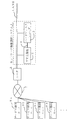
Hereinafter, an embodiment of the present invention will be described with reference to the drawings. In the present embodiment, the electrical device of the present invention is an IPTV (Internet Protocol Television) type network television receiver (hereinafter referred to as a TV receiver), and other devices are hard disk recorders that can be connected to the network. An example will be described. FIG. 1 shows a network
また、図1に示されるように、TV受像機2とハードディスクレコーダ3とは、LAN(Local Area Network)6に接続されており、このLAN6とルータ5とを介してインターネット7に接続されている。TV受像機2とハードディスクレコーダ3とは、LAN6とルータ5とを介してインターネット7上のサービス提供サーバ8(図中の複数のサービス提供サーバ8a,8b,8c,8d等の総称)とアクセス可能である。各サービス提供サーバ8は、アクトビラ(登録商標)等のポータルサービスや、VOD(Video On Demand)(のサービス)や、ニュース配信サービス等の各種のネットワークサービスを提供する(サービスプロバイダ側に配された)サーバである。TV受像機2とハードディスクレコーダ3とは、LAN6とルータ5とインターネット7とを介して各サービス提供サーバ8に接続して、各サービス提供サーバ8から各種のネットワークサービスの提供を受ける機能(以下、ネットワーク機能と略す)を有している。なお、ここで、上記のネットワーク機能は、ブラウザ等のソフトウェアや、アプリケーション・プラットフォーム等のミドルウェアや、ネットワークカード等に含まれる通信用のインタフェース回路等のハードウェアにより実現される。
As shown in FIG. 1, the
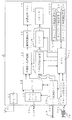
図2は、TV受像機2の概略の電気的ブロック図である。TV受像機2は、装置全体の制御を行うCPU11(同機能有無判定手段、他機器設定指示手段)と、チューナ12と、ネットワークカード13と、デコーダ14と、映像信号処理回路15と、電極駆動回路16と、液晶表示パネル17(表示手段)と、音声信号処理回路19と、アンプ20と、スピーカ21と、HDMIレシーバ22(請求項における通信手段)とを備えている。
FIG. 2 is a schematic electrical block diagram of the
チューナ12は、アンテナ31を介して受信したディジタルテレビジョン放送をデコーダ14に送る。ネットワークカード13は、LAN端子2aと不図示のLANケーブルを介して、図1に示されるLAN6と接続されており、各サービス提供サーバ8から送信されたネットワークサービス提供用の各種データを受信すると共に、サービス提供サーバ8に対して各種のコマンド及びレスポンスの送受信を行うためのインタフェース用の回路である。デコーダ14は、ディジタルテレビジョン放送のデコード用のデコーダだけではなく、各種のネットワークサービスのコンテンツをデコードするためのデコーダを内蔵しており、チューナ12から送られたディジタルテレビジョン放送や、ネットワークカード13から送られたネットワークサービスのコンテンツのデコードを行って、ディジタルテレビジョン放送又はネットワークサービスのコンテンツに基づく映像信号と音声信号とを、それぞれ映像信号処理回路15と音声信号処理回路19とに出力する。
The tuner 12 sends the digital television broadcast received via the antenna 31 to the decoder 14. The network card 13 is connected to the
上記の映像信号処理回路15は、デコーダ14から送られた(ディジタルテレビジョン放送又はネットワークサービスのコンテンツに基づく)映像信号、又はHDMIレシーバ20とHDMIケーブル4を介してハードディスクレコーダ3から送られた映像信号に対して各種の映像信号処理を行って、電極駆動回路16に送る。電極駆動回路16は、映像信号処理回路15から受信した映像信号に基づいて、表示用電極を駆動することにより、液晶表示パネル17に映像信号に基づく映像を表示する。
The video signal processing circuit 15 is a video signal sent from the decoder 14 (based on digital television broadcast or network service content) or a video sent from the
音声信号処理回路19は、デコーダ14から送られた(ディジタルテレビジョン放送又はネットワークサービスのコンテンツに基づく)音声信号、又はHDMIレシーバ22とHDMIケーブル4を介してハードディスクレコーダ3から送られた音声信号に対して、各種の音声信号処理やD/A変換処理を行った後、これらの処理後のアナログの音声信号をアンプ20に送る。アンプ20は、音声信号処理回路19から受信したアナログの音声信号を増幅してスピーカ21に出力する。スピーカ21は、アンプ20により増幅された後のアナログの音声信号に基づく音声を出力する。
The audio
HDMIレシーバ22は、HDMI端子2bを介して入力されたHDMI信号を受信して映像信号や音声信号に復号し、復号した映像信号と音声信号とを、それぞれ映像信号処理回路15と音声信号処理回路19とに出力する。
The HDMI receiver 22 receives an HDMI signal input via the
また、TV受像機2は、各種の制御用のプログラムやデータを記憶したメモリ23を有している。このメモリ23に記憶されたプログラムには、TV受像機2とハードディスクレコーダ3とに共通するネットワーク機能について、いずれかの側のネットワーク機能を制限するための処理を行うプログラムであるネットワーク機能制限プログラム(以下、ネットワーク機能制限PGという)24が含まれている。また、メモリ23に記憶されたデータには、TV受像機2が元々有しているネットワーク機能についての情報(TV受像機2が、どのネットワークサービスの提供を受ける機能を有しているかについての情報)であるネットワーク機能情報25と、TV受像機2が元々有している各ネットワーク機能のうち、どの機能が使用可能に設定されており、どの機能が使用不可に設定されているかについての情報であるネットワーク機能制限情報26とが含まれている。
The
また、TV受像機2は、装置本体とは別体のリモートコントローラ(以下、リモコンと略す)30と、このリモコン30から送信されたリモートコントロール信号(以下、リモコン信号と略す)を受信するためのリモコン信号受信部27とを有している。リモコン30は、各サービス提供サーバ8から提供される各種のネットワークサービスに対応した各種のアイコンを含むネットワークサービス選択画面(図5参照)を表示するようにユーザが指示するためのネットボタン30aを有している。
The
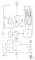
図3は、ハードディスクレコーダ3の概略の電気的ブロック図である。ハードディスクレコーダ3は、装置全体の制御を行うCPU41(他機器側機能制限設定手段)と、チューナ42と、ネットワークカード43と、デコーダ44と、エンコーダ45と、ハードディスク46を内蔵したHDD(ハードディスクドライブ)47と、HDMIトランスミッタ48と、表示部49とを備えている。
FIG. 3 is a schematic electrical block diagram of the
上記のチューナ42は、アンテナ61を介して受信した録画用のディジタルテレビジョン放送をデコーダ44に送る。ネットワークカード43は、LAN端子3aと不図示のLANケーブルとを介して、図1に示されるLAN6と接続されており、各サービス提供サーバ8から送信されたネットワークサービス提供用の各種データを受信すると共に、サービス提供サーバ8に対して各種のコマンド及びレスポンスの送受信を行うためのインタフェース用の回路である。デコーダ44は、ディジタルテレビジョン放送のデコード用のデコーダだけではなく、各種のネットワークサービスのコンテンツをデコードするためのデコーダを内蔵しており、チューナ42から送られたディジタルテレビジョン放送や、ネットワークカード43から送られたネットワークサービスのコンテンツのデコードを行って、ディジタルテレビジョン放送又はネットワークサービスのコンテンツに基づく映像信号と音声信号とを再生する。
The tuner 42 sends the recording digital television broadcast received via the
また、上記のエンコーダ45は、デコーダ44で再生(デコード)された映像信号や音声信号を、ハードディスク46に適した圧縮方法と圧縮率で圧縮してHDD47に送る処理を行う。上記のHDD47は、エンコーダ42で圧縮された映像信号や音声信号をハードディスク46に記録すると共に、ハードディスク46に記録された圧縮形式の映像信号及び音声信号を読み出す。上記のデコーダ44は、HDD47によりハードディスク46から読み出された圧縮形式の映像信号及び音声信号のデコードも行う。
The
上記のHDMIトランスミッタ48は、デコーダ44から送られたデコード後の映像信号及び音声信号を、HDMI端子3bとHDMIケーブル4とを介して、TV受像機2に送信する。また、表示部49は、各種のメッセージの表示等に用いられる。
The
また、ハードディスクレコーダ3は、各種の制御用のプログラムやデータを記憶したメモリ50を有している。このメモリ50に記憶されたプログラムには、TV受像機2とハードディスクレコーダ3とに共通するネットワーク機能について、ハードディスクレコーダ3側のネットワーク機能を制限するための処理を行うプログラムであるネットワーク機能制限プログラム(以下、ネットワーク機能制限PGという)51が含まれている。また、メモリ50に記憶されたデータには、ハードディスクレコーダ3が元々有しているネットワーク機能についての情報(ハードディスクレコーダ3が、どのネットワークサービスの提供を受ける機能を有しているかについての情報)であるネットワーク機能情報52と、ハードディスクレコーダ3が元々有している各ネットワーク機能のうち、どの機能が使用可能に設定されており、どの機能が使用不可に設定されているかについての情報であるネットワーク機能制限情報53とが含まれている。
The
また、ハードディスクレコーダ3は、装置本体とは別体のリモートコントローラ(以下、リモコンと略す)60と、このリモコン60から送信されたリモートコントロール信号(以下、リモコン信号と略す)を受信するためのリモコン信号受信部54とを有している。
The
本ネットワーク機能選択システム1では、TV受像機2とハードディスクレコーダ3とに共通するネットワーク機能について、いずれかの側のネットワーク機能を制限することができる。このネットワーク機能を制限するための設定処理について、図4のフローチャートに加えて、図5及び図6を参照して説明する。以下の処理は、TV受像機2のCPU11が、図2に示されるネットワーク機能制限PG24に基づいて行う。
In the network
図4のフローチャートに示されるように、TV受像機2の電源がオンにされると(TV受像機2の主電源がオンにされるか、又はTV受像機2がスタンバイ状態から通常のオン状態にされると)(S1でYES)、TV受像機2のCPU11は、TV受像機2とHDMI接続されている機器が存在するか否かを判定する(S2)。そして、HDMI接続されている機器が存在する場合には(S2でYES)、相手側(接続相手)の機器(ハードディスクレコーダ3)がTV受像機2と同じ種類のCECベンダーコマンドに対応しているか否か(基本的には、相手側の機器がTV受像機2と同じ製造メーカの機器であるか否か)を判定する(S3)。
As shown in the flowchart of FIG. 4, when the
上記S3の判定の結果、相手側の機器が同じ種類のCECベンダーコマンドに対応している場合には、TV受像機2のCPU11は、相手側の機器にCECベンダーコマンドを送信して、相手側の機器がTV受像機2と同じ(種類の)ネットワーク機能を有しているか否かを判定する(S4)。言い換えると、TV受像機2のCPU11が、相手側の機器が有するネットワーク機能の中に、自機の有するネットワーク機能と共通するネットワーク機能が存在するか否かを判定する。より具体的には、TV受像機2のCPU11が、相手側の機器であるハードディスクレコーダ3に対して、CECベンダーコマンドを送信して、ハードディスクレコーダ3のメモリ50に記憶されたネットワーク機能情報52の内容を送信するように指示する。そして、TV受像機2のCPU11は、ハードディスクレコーダ3から受信したネットワーク機能情報52の内容と、自機のメモリ23に記憶されたネットワーク機能情報25の内容とに基づいて、ハードディスクレコーダ3が有する機能の中に、自機の有する機能と共通する機能が存在するか否かを判定する。
If the result of the determination in S3 is that the counterpart device is compatible with the same type of CEC vendor command, the CPU 11 of the
上記S4の判定の結果、相手側の機器(ハードディスクレコーダ3)がTV受像機2と同じネットワーク機能を有している場合(TV受像機2と相手側の機器とで共通するネットワーク機能が存在する場合)には(S4でYES)、TV受像機2のCPU11は、図2に示されるメモリ23に記憶された不図示のフラグ情報を見て、以前に(既に)、図5に示される機能制限確認入力画面71を表示したことがあるか否かを判定する(S5)。この機能制限確認入力画面71は、TV受像機2と相手側の機器とで共通するネットワーク機能について、この機能をTV受像機2で使用可能にするか、使用不可にするかを、ユーザが設定入力するための画面である。
As a result of the determination in S4, when the counterpart device (hard disk recorder 3) has the same network function as the
上記S5の判定の結果、以前に(未だ)機能制限確認入力画面71を表示したことがない場合には(S5でNO)、TV受像機2のCPU11は、図5に示される機能制限確認入力画面71を自動的に表示し(S6)、ユーザに対して、TV受像機2における各ネットワーク機能の使用の可否を設定入力するように促す。
As a result of the determination in S5, when the function restriction confirmation input screen 71 has not been displayed before (NO in S5), the CPU 11 of the
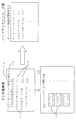
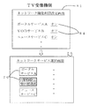
ここで、図5に示される機能制限確認入力画面71に表示される内容について説明する。この機能制限確認入力画面71には、ユーザに対して、TV受像機2とハードディスクレコーダ3とで共通するネットワーク機能が存在することを知らせると共に、TV受像機2における各ネットワーク機能の使用の可否を、リモコン30を用いて設定入力するように促すための確認メッセージ72と、TV受像機2とハードディスクレコーダ3とで共通するネットワーク機能に対応するネットワークサービス名を表示するネットワークサービス名表示欄73と、TV受像機2における各ネットワーク機能の使用の可否を設定入力するための機能制限設定入力欄74とが配設されている。図中の機能制限設定入力欄74における「オン」と「オフ」とは、それぞれ各ネットワーク機能の「使用可能」の設定と、「使用不可」の設定とを表している。この機能制限確認入力画面71とリモコン30とが、請求項における機能制限設定手段に相当する。
Here, the contents displayed on the function restriction confirmation input screen 71 shown in FIG. 5 will be described. The function restriction confirmation input screen 71 informs the user that there is a network function common to the
図4のフローチャートに戻って、ユーザによるリモコン30と機能制限確認入力画面71とを用いた、各ネットワーク機能の使用の可否の設定入力が完了すると(S7でYES)、TV受像機2のCPU11は、自機において使用可能に設定された機能を、ハードディスクレコーダ3では使用不可に設定し、自機において使用不可に設定された機能を、ハードディスクレコーダ3では使用可能に設定するように、CECベンダーコマンドを用いてハードディスクレコーダ3に指示する。そして、ハードディスクレコーダ3側のCPU41は、ネットワーク機能制限PG51に基づき、上記のTV受像機2からの指示内容に応じて、TV受像機2と共通するネットワーク機能のうち、TV受像機2側において使用可能に設定されたネットワーク機能を、ハードディスクレコーダ3側では使用不可に設定し、TV受像機2側において使用不可に設定されたネットワーク機能を、ハードディスクレコーダ3側では使用可能に設定する。これにより、TV受像機2側のネットワーク機能制限情報26とハードディスクレコーダ3側のネットワーク機能制限情報53とは、上記の一連の処理の結果を反映したものになる。
Returning to the flowchart of FIG. 4, when the user inputs the setting of availability of each network function using the remote control 30 and the function restriction confirmation input screen 71 (YES in S7), the CPU 11 of the
この後、TV受像機2のCPU11は、前回の電源切断前におけるTV受像機2の状態に応じて(電源切断前の入力モードに応じて)、通常の初期画面(チューナ12で受信したディジタルテレビジョン放送の画像の画面、ハードディスクレコーダ3から入力された画像の画面、又は図5に示されるネットワークサービス選択画面75)を液晶表示パネル17に表示する(S8)。
Thereafter, the CPU 11 of the
上記の図5に示されるネットワークサービス選択画面75は、各サービス提供サーバ8から提供される各種のネットワークサービスをユーザが(視聴するために)選択するための画面であり、各種のネットワークサービスに対応した各種のアイコン76を有している。
The network
上記S7で設定入力した各ネットワーク機能の使用の可否の設定内容が、図5中の機能制限設定入力欄74に示される内容(全てオン(使用可能))であるときには、図5に示されるように、ネットワークサービス選択画面75における各アイコン76は、全て、通常の選択可能状態(例えば、白抜きの枠内にネットワークサービス名が表示される状態)で表示される。この状態では、ネットワークサービス選択画面75に表示された全てのアイコン76を選択可能である。言い換えれば、TV受像機2側の全てのネットワーク機能を使用可能である。これに対して、図5中のハードディスクレコーダ3側のネットワーク機能情報52に示されるように、ハードディスクレコーダ3側の全てのネットワーク機能が使用不可である。このように、TV受像機2側とハードディスクレコーダ3側における使用可否の設定内容は、逆になる。
When the setting contents indicating whether or not each network function is set and input in S7 is the contents shown in the function restriction setting
また、図6中の機能制限確認入力画面71に示されるように、上記S7で設定入力した各ネットワーク機能の使用の可否の設定内容にオフ(使用不可)のものが含まれている場合には、ネットワークサービス選択画面75において、上記のオフに設定されたネットワーク機能(VODサービスBに対応するネットワーク機能)のアイコン76は、選択不可の状態(例えば、図6に示されるグレーの枠内にネットワークサービス名が表示された状態)で表示される。
Further, as shown in the function restriction confirmation input screen 71 in FIG. 6, when the setting details of whether or not each network function is set and input in S <b> 7 includes an off (unusable) setting. On the network
なお、TV受像機2側の初期設定画面には、図7に示されるように、上記図5及び図6に示される機能制限確認入力画面71と同様な設定入力を行うためのネットワーク機能制限設定画面81が含まれており、ユーザは、以前に機能制限確認入力画面71を表示したことがある場合でも、このネットワーク機能制限設定画面81における機能制限設定入力欄84に設定入力することにより、TV受像機2における各ネットワーク機能の使用の可否を設定入力することができる。
In the initial setting screen on the
上記のように、本実施形態のTV受像機2によれば、同じ(共通する)ネットワーク機能を有する他の機器(ハードディスクレコーダ3)と接続した場合でも、この共通するネットワーク機能について、自機におけるネットワーク機能を使用可能にするか、使用不可にするかをユーザが設定することができるので、ユーザが、TV受像機2側のネットワーク機能とハードディスクレコーダ3側のネットワーク機能のうちの、いずれのネットワーク機能を使用しているか容易に判断することができる。これにより、ユーザの混乱を防ぐことができるので、ユーザが、例えば、ハードディスクレコーダ3側のネットワーク機能を使用しているときに、TV受像機2側の機能を使用していると誤解して、ハードディスクレコーダ3側の電源をオフにしてしまう等の誤操作をしてしまうことを防ぐことができる。
As described above, according to the
また、上記のTV受像機2とハードディスクレコーダ3とで共通するネットワーク機能のうち、TV受像機2において使用可能に設定されたネットワーク機能を、ハードディスクレコーダ3では使用不可に設定し、TV受像機2において使用不可に設定されたネットワーク機能を、ハードディスクレコーダ3では使用可能に設定するように、ハードディスクレコーダ3に指示することができるので、ユーザが、TV受像機2側のネットワーク機能とハードディスクレコーダ3側のネットワーク機能のうちの、いずれのネットワーク機能を使用しているかを、より容易に判断することができる。
Of the network functions common to the
また、上記のTV受像機2とハードディスクレコーダ3とで共通するネットワーク機能が存在するときに、この共通するネットワーク機能について、TV受像機2におけるネットワーク機能を使用可能にするか、使用不可にするかを設定入力するための機能制限確認入力画面71を自動的に表示することができるので、ユーザに対して、この機能制限確認入力画面71を用いて、TV受像機2におけるネットワーク機能を使用可能にするか、使用不可にするかを設定入力するように促すことができる。
Also, when there is a common network function between the
なお、本発明は、上記実施形態の構成に限られず、発明の趣旨を変更しない範囲で種々の変形が可能である。例えば、上記実施形態では、本発明をネットワークテレビジョン受像機に適用した場合の例を示したが、本発明を、ネットワークテレビジョン受像機以外の映像音響機器等の電気機器に適用してもよい。また、上記実施形態では、本発明の電気機器に接続される他の機器が、ハードディスクレコーダ3である場合の例を示したが、他の機器は、例えば、BDプレーヤ、BDレコーダ、DVDプレーヤ、DVDレコーダ等の電気機器であってもよい。
In addition, this invention is not restricted to the structure of the said embodiment, A various deformation | transformation is possible in the range which does not change the meaning of invention. For example, in the above-described embodiment, an example in which the present invention is applied to a network television receiver has been described. However, the present invention may be applied to an electrical apparatus such as an audiovisual apparatus other than the network television receiver. . In the above embodiment, the example in which the other device connected to the electric device of the present invention is the
さらにまた、上記実施形態では、本発明において使用可否の設定対象となる機能が、ネットワーク機能である場合の例を示したが、設定対象となる機能は、これに限られず、例えば、テレビジョン受像機とチューナ機能を有する録画機器(ハードディスクレコーダ、BDレコーダ、DVDレコーダ等)とを接続した場合における番組表の出力機能であってもよい。また、上記の機能が、音声やメニュー表示文字における言語設定機能であってもよい。 Furthermore, in the above-described embodiment, an example in which the function to be set for availability in the present invention is a network function is shown, but the function to be set is not limited to this, for example, a television receiver. It may be a program guide output function when a recorder and a recording device having a tuner function (hard disk recorder, BD recorder, DVD recorder, etc.) are connected. Further, the above function may be a language setting function for voice and menu display characters.
1 ネットワーク機能選択システム(電気機器システム)
2 TV受像機(電気機器)
3 ハードディスクレコーダ(他の機器)
7 インターネット(ネットワーク)
8 サービス提供サーバ
11 CPU(同機能有無判定手段、他機器設定指示手段)
17 液晶表示パネル(表示手段)
22 HDMIレシーバ(通信手段)
30 リモコン(機能制限設定手段)
41 CPU(他機器側機能制限設定手段)
71 機能制限確認入力画面(機能制限設定手段)
1 Network function selection system (electric equipment system)
2 TV receiver (electrical equipment)
3 Hard disk recorder (other devices)
7 Internet (network)
8 Service providing server 11 CPU (same function presence / absence judging means, other equipment setting instructing means)
17 Liquid crystal display panel (display means)
22 HDMI receiver (communication means)
30 Remote control (Function restriction setting means)
41 CPU (other device side function restriction setting means)
71 Function restriction confirmation input screen (Function restriction setting means)
Claims (6)
前記通信手段を用いて、前記他の機器が有する機能の中に、自機の有する機能と共通する機能が存在するか否かを判定する同機能有無判定手段と、
前記同機能有無判定手段による判定の結果、共通する機能が存在すると判定されたときに、自機における前記共通する機能を使用可能にするか、使用不可にするかをユーザが設定するための機能制限設定手段とをさらに備えたことを特徴とする電気機器。 In an electrical device having a communication means for communicating with other devices,
Using the communication means, the same function presence / absence determining means for determining whether or not a function common to the function of the own device exists among the functions of the other device,
A function for the user to set whether the common function is enabled or disabled when it is determined that the common function exists as a result of the determination by the same function presence / absence determination unit An electric device, further comprising a restriction setting unit.
前記機能制限設定手段は、前記同機能有無判定手段による判定の結果、共通する機能が存在すると判定されたときに、自機における前記共通する機能を使用可能にするか、使用不可にするかを設定入力するための機能制限確認入力画面を前記表示手段に自動的に表示することを特徴とする請求項1又は請求項2に記載の電気機器。 A display means,
The function restriction setting means determines whether to enable or disable the common function in its own device when it is determined that the common function exists as a result of the determination by the same function presence / absence determination means. The electric device according to claim 1 or 2, wherein a function restriction confirmation input screen for setting input is automatically displayed on the display means.
前記他の機器が有する機能及び前記自機の有する機能は、前記サービス提供サーバに接続して、前記サービス提供サーバから前記ネットワークサービスの提供を受ける機能であることを特徴とする請求項1乃至請求項3のいずれか一項に記載の電気機器。 It can be connected via a network to a service providing server that provides network services,
The function of the other device and the function of the own device are functions of connecting to the service providing server and receiving the network service from the service providing server. Item 4. The electric device according to any one of Items 3.
前記電気機器は、
前記通信手段を用いて、前記他の機器が有する機能の中に、前記電気機器の有する機能と共通する機能が存在するか否かを判定する同機能有無判定手段と、
前記同機能有無判定手段による判定の結果、共通する機能が存在すると判定されたときに、前記電気機器における前記共通する機能を使用可能にするか、使用不可にするかを設定する機能制限設定手段と、
前記共通する機能のうち、前記機能制限設定手段により前記電気機器において使用可能に設定された機能を、前記他の機器では使用不可に設定し、前記機能制限設定手段により前記電気機器において使用不可に設定された機能を、前記他の機器では使用可能に設定するように、前記通信手段を用いて前記他の機器に指示する他機器設定指示手段をさらに備え、
前記他の機器は、前記電気機器側における前記他機器設定指示手段による指示内容に応じて、前記共通する機能のうち、前記機能制限設定手段により前記電気機器側において使用可能に設定された機能を、該他の機器側では使用不可に設定し、前記機能制限設定手段により前記電気機器側において使用不可に設定された機能を、該他の機器側では使用可能に設定する他機器側機能制限設定手段を備えたことを特徴とする電気機器システム。 In an electric device system including an electric device provided with a communication means for communicating with another device, and the other device,
The electrical equipment is
Using the communication means, the same function presence / absence determining means for determining whether or not a function common to the function of the electrical device exists among the functions of the other device,
As a result of the determination by the same function presence / absence determination means, when it is determined that a common function exists, a function restriction setting means for setting whether to enable or disable the common function in the electrical device When,
Among the common functions, a function that is set to be usable in the electric device by the function restriction setting unit is set to be unusable in the other device, and is not usable in the electric device by the function limit setting unit. In order to set the set function to be usable in the other device, the device further comprises other device setting instruction means for instructing the other device using the communication means,
The other device has a function set to be usable on the electric device side by the function restriction setting unit among the common functions according to the instruction content by the other device setting instruction unit on the electric device side. The other device side function restriction setting is set to disable use on the other device side, and the function set to be disabled on the electric device side by the function restriction setting means is set to be usable on the other device side. An electrical equipment system comprising means.
前記他の機器が有する機能及び前記電気機器の有する機能は、前記サービス提供サーバに接続して、前記サービス提供サーバから前記ネットワークサービスの提供を受ける機能であることを特徴とする請求項5に記載の電気機器システム。 The electrical device and the other device are connectable via a network with a service providing server that provides a network service,
6. The function of the other device and the function of the electric device are functions of connecting to the service providing server and receiving the network service from the service providing server. Electrical equipment system.
Priority Applications (1)
| Application Number | Priority Date | Filing Date | Title |
|---|---|---|---|
| JP2011061481A JP2012199681A (en) | 2011-03-18 | 2011-03-18 | Electric apparatus and electric apparatus system |
Applications Claiming Priority (1)
| Application Number | Priority Date | Filing Date | Title |
|---|---|---|---|
| JP2011061481A JP2012199681A (en) | 2011-03-18 | 2011-03-18 | Electric apparatus and electric apparatus system |
Publications (1)
| Publication Number | Publication Date |
|---|---|
| JP2012199681A true JP2012199681A (en) | 2012-10-18 |
Family
ID=47181495
Family Applications (1)
| Application Number | Title | Priority Date | Filing Date |
|---|---|---|---|
| JP2011061481A Withdrawn JP2012199681A (en) | 2011-03-18 | 2011-03-18 | Electric apparatus and electric apparatus system |
Country Status (1)
| Country | Link |
|---|---|
| JP (1) | JP2012199681A (en) |
-
2011
- 2011-03-18 JP JP2011061481A patent/JP2012199681A/en not_active Withdrawn
Similar Documents
| Publication | Publication Date | Title |
|---|---|---|
| US8490140B2 (en) | Electronic device and method, recording medium, and program | |
| US8650334B2 (en) | Source device, sink device, system, and recording medium | |
| US20090249420A1 (en) | Method for configuring video apparatus according to video system and content, and video apparatus and server applying the same | |
| JP5207860B2 (en) | Video / audio playback apparatus and video / audio playback method | |
| US8212827B2 (en) | Mode conversion method and display apparatus using the same | |
| US20080098318A1 (en) | Method for providing menu screen suitable for menus provided by external device and imaging device using the same | |
| JP2009200788A (en) | Receiving device | |
| JP2015191515A (en) | Electronic equipment | |
| JP2012213131A (en) | Input switching device | |
| EP2003889A2 (en) | A display apparatus and method for determining the status of an audio interface | |
| EP2337351A1 (en) | Information processing device, display device, and information processing system | |
| US8875214B2 (en) | Television | |
| JPWO2011138884A1 (en) | AV output system for video output | |
| US20140223470A1 (en) | Method and apparatus for reproducing contents | |
| US20110131616A1 (en) | Terminal device, media processing apparatus connected to terminal device, and controlling method thereof | |
| JP2014007507A (en) | Electronic apparatus and display control method | |
| JP5649861B2 (en) | Display device, system, control method, program, and recording medium | |
| KR20090018460A (en) | Video apparatus for converting video output mode of external video and the method thereof | |
| JP2015050709A (en) | Controller, control method and program | |
| WO2012172850A1 (en) | Device operating system, display device, and operating device | |
| JP2010200088A (en) | Video apparatus | |
| JP2012199681A (en) | Electric apparatus and electric apparatus system | |
| EP2568714A1 (en) | Content reproducing apparatus, content reproducing system, and control method thereof | |
| JP5752550B2 (en) | Service providing system, terminal device, and control program | |
| JP2014112747A (en) | And content reproduction method |
Legal Events
| Date | Code | Title | Description |
|---|---|---|---|
| A300 | Withdrawal of application because of no request for examination |
Free format text: JAPANESE INTERMEDIATE CODE: A300 Effective date: 20140603 |