JP2012199189A - Connector - Google Patents
Connector Download PDFInfo
- Publication number
- JP2012199189A JP2012199189A JP2011063929A JP2011063929A JP2012199189A JP 2012199189 A JP2012199189 A JP 2012199189A JP 2011063929 A JP2011063929 A JP 2011063929A JP 2011063929 A JP2011063929 A JP 2011063929A JP 2012199189 A JP2012199189 A JP 2012199189A
- Authority
- JP
- Japan
- Prior art keywords
- terminal
- accommodating chamber
- locking
- locking lance
- connector
- Prior art date
- Legal status (The legal status is an assumption and is not a legal conclusion. Google has not performed a legal analysis and makes no representation as to the accuracy of the status listed.)
- Abandoned
Links
Images


Abstract
Description
本発明は、コネクタに関する。 The present invention relates to a connector.
従来、コネクタとしては、端子としての端子金具を収容しこの端子金具の接続部としての舌片側が開口された端子収容室としてのキャビティと、このキャビティ内に撓み可能に設けられ端子金具を係止する係止ランスとしてのランスと、キャビティの開口側の両側壁に設けられ端子金具の幅方向両側の下面側を支持する一対の支持部としての一対の支持面とを備えたものが知られている(例えば、特許文献1参照)。 Conventionally, as a connector, a terminal metal fitting as a terminal is accommodated and a cavity as a terminal accommodating chamber in which a tongue piece side as a connecting portion of the terminal metal fitting is opened, and the terminal metal fitting is provided in the cavity so as to be bent. And a pair of support surfaces as a pair of support portions that are provided on both side walls on the opening side of the cavity and support the lower surface sides on both sides in the width direction of the terminal fitting. (For example, refer to Patent Document 1).
このコネクタでは、一対の支持面がキャビティの幅方向両側から張り出して形成され、一対の支持面により端子金具の幅方向両側の下面側を支持することによって、キャビティ内における端子金具の落ち込みを規制している。 In this connector, a pair of support surfaces are formed so as to protrude from both sides of the cavity in the width direction, and the lower surfaces of both sides of the terminal metal in the width direction are supported by the pair of support surfaces, thereby restricting the drop of the terminal metal in the cavity. ing.
しかしながら、上記のようなコネクタでは、端子収容室の両側壁に設けられた一対の支持部の張り出しが少ないので、端子収容室内で端子が少しでも回転してしまうと、一対の支持部の間から端子が落ち込む恐れがあり、端子収容室内に端子を安定して保持することができなかった。 However, in the connector as described above, since the pair of support portions provided on both side walls of the terminal accommodating chamber has few overhangs, if the terminal rotates even a little in the terminal accommodating chamber, the gap between the pair of supporting portions The terminal may fall, and the terminal could not be stably held in the terminal accommodating chamber.
そこで、この発明は、端子収容室内に端子を安定して保持することができるコネクタの提供を目的としている。 Therefore, an object of the present invention is to provide a connector that can stably hold a terminal in a terminal accommodating chamber.
請求項1記載の発明は、端子を収容しこの端子の接続部側が開口された端子収容室と、この端子収容室内に撓み可能に設けられ前記端子の被係止部に係合される係止部が設けられた係止ランスと、前記端子収容室の開口側の両側壁に設けられ前記端子の幅方向両側の下面側を支持する一対の支持部とを備えたコネクタであって、前記係止ランスは、前記係止部から前記開口に向けて延設され前記係止部が前記被係止部と係合した状態で前記一対の支持部と共に前記端子の下面側を支持する端子支持部が設けられていることを特徴とする。 According to the first aspect of the present invention, there is provided a terminal accommodating chamber in which a terminal is accommodated and the connecting portion side of the terminal is opened, and a latch provided in the terminal accommodating chamber so as to be bent and engaged with a locked portion of the terminal. And a pair of support portions provided on both side walls on the opening side of the terminal accommodating chamber and supporting the lower surface sides on both sides in the width direction of the terminal. The stop lance extends from the locking portion toward the opening, and the terminal support portion supports the lower surface side of the terminal together with the pair of support portions in a state where the locking portion is engaged with the locked portion. Is provided.
このコネクタでは、係止ランスに係止部から開口に向けて延設され係止部が被係止部と係合した状態で一対の支持部と共に端子の下面側を支持する端子支持部が設けられているので、一対の支持部の間で端子を係止ランスの端子支持部によって支持することができ、端子が一対の支持部の間から脱落することを防止することができる。 In this connector, a terminal support portion is provided on the locking lance so as to extend from the locking portion toward the opening and support the lower surface side of the terminal together with the pair of supporting portions in a state where the locking portion is engaged with the locked portion. Thus, the terminal can be supported by the terminal support portion of the locking lance between the pair of support portions, and the terminal can be prevented from falling off between the pair of support portions.
従って、このようなコネクタでは、端子収容室内に端子を安定して保持することができる。 Therefore, in such a connector, the terminal can be stably held in the terminal accommodating chamber.
また、係止ランスの端子支持部は、係止部から開口に向けて延設されているので、端子収容室内に端子を収容した状態で、開口から係止ランスと端子収容室との間に挿入される端子の導通を検出する検出部材や係止ランスの係合状態を検出し係止ランスの撓みを規制する規制部材などの長さを縮小することができ、検出部材や規制部材などの強度を向上することができる。このため、検出部材や規制部材などの厚みも薄くすることができ、検出部材や規制部材などを小型化することができる。 In addition, since the terminal support portion of the locking lance extends from the locking portion toward the opening, the terminal is accommodated between the opening and the locking lance and the terminal accommodating chamber in a state where the terminal is accommodated in the terminal accommodating chamber. It is possible to reduce the length of the detection member that detects the conduction of the inserted terminal and the restriction member that detects the engagement state of the locking lance and restricts the bending of the locking lance. Strength can be improved. For this reason, thickness of a detection member, a control member, etc. can also be made thin, and a detection member, a control member, etc. can be reduced in size.
請求項2記載の発明は、請求項1記載のコネクタであって、前記係止ランスの下面は、この下面と対向する前記端子収容室の内壁面と略平行に形成されていることを特徴とする。 The invention according to claim 2 is the connector according to claim 1, wherein the lower surface of the locking lance is formed substantially parallel to the inner wall surface of the terminal accommodating chamber facing the lower surface. To do.
このコネクタでは、係止ランスの下面がこの下面と対向する端子収容室の内壁面と略平行に形成されているので、係止ランスの下面と端子収容室の内壁面との間の距離を、開口から係止ランスと端子収容室との間に挿入される小型化された検出部材や規制部材などに合わせて縮小することができ、コネクタ全体を小型化することができる。 In this connector, since the lower surface of the locking lance is formed substantially parallel to the inner wall surface of the terminal accommodating chamber facing the lower surface, the distance between the lower surface of the locking lance and the inner wall surface of the terminal accommodating chamber is It is possible to reduce the size of the connector in accordance with a downsized detection member or a restriction member inserted between the locking lance and the terminal accommodating chamber from the opening, and the entire connector can be downsized.
本発明によれば、端子収容室内に端子を安定して保持することができるコネクタを提供することができるという効果を奏する。 According to the present invention, there is an effect that it is possible to provide a connector that can stably hold a terminal in a terminal accommodating chamber.
図1〜図6を用いて本発明の実施の形態に係るコネクタについて説明する。 A connector according to an embodiment of the present invention will be described with reference to FIGS.
(第1実施形態)
図1〜図5を用いて第1実施形態について説明する。
(First embodiment)
The first embodiment will be described with reference to FIGS.
本実施の形態に係るコネクタ1は、端子3を収容しこの端子3の接続部5側が開口された端子収容室7と、この端子収容室7内に撓み可能に設けられ端子3の被係止部9に係合される係止部11が設けられた係止ランス13と、端子収容室7の開口15側の両側壁17,19に設けられ端子3の幅方向両側の下面21側を支持する一対の支持部23,25とを備えている。
The connector 1 according to the present embodiment includes a
そして、係止ランス13は、係止部11から開口15に向けて延設され係止部11が被係止部9と係合した状態で一対の支持部23,25と共に端子3の下面21側を支持する端子支持部27が設けられている。
The
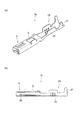
図1,図2に示すように、端子3は、導電性材料からなり、雄端子3aと雌端子3bとを有し、接続部5と電線固定部29と被係止部9とを備えている。雄端子3aの接続部5はタブ31を有し、雌端子3bの接続部5はバネ33を有している。また、雄端子3a及び雌端子3bの電線固定部29は、被覆電線(不図示)の芯線が導通して加締められる芯線固定部35と、被覆電線の被覆部を加締めて被覆電線を固定する被覆固定部37とを有する。これらの雄端子3a及び雌端子3bには、接続部5と電線固定部29との間に端子3を端子収容室7内に係止させるためのランスホールからなる被係止部9が設けられている。なお、以下では、端子収容室7内に雌端子3bが収容されることとして雌端子3bを端子3として説明するが、雄端子3aを端子3とした場合でも雌端子3bと同様に機能し、得られる効果は同様である。
As shown in FIGS. 1 and 2, the
図3〜図5に示すように、コネクタ1は、端子収容室7と係止ランス13と一対の支持部23,25とを備えている。端子収容室7は、ハウジング39の幅方向に複数列(ここでは4列)設けられ、ハウジング39の高さ方向に複数段(ここでは2段)設けられている。また、各端子収容室7は、ハウジング39の相手ハウジング(不図示)に対する嵌合方向に延設されており、挿入口41側から端子3が挿入され、開口15側に端子3の接続部5側が配置される。このように端子収容室7に端子3を収容することによって、ハウジング39を相手ハウジングと嵌合することにより、開口15側の接続部挿入口43から相手端子のタブ31(図1参照)が挿通され、各端子3の接続部5と各相手端子とが接続される。このような端子収容室7に収容された端子3は、係止ランス13によって係止され、端子収容室7からの抜けが防止される。
As shown in FIGS. 3 to 5, the connector 1 includes a
係止ランス13は、端子収容室7内に撓み可能に設けられ、撓み方向の上方に突出する係止部11が設けられている。この係止ランス13は、挿入口41側から端子収容室7内に端子3が収容されたときに、係止部11の挿入口41側の傾斜面45が端子3と当接することによって下方に撓まされる。この状態から端子3を開口15側に向けて挿入することにより、係止部11が被係止部9に位置したときに上方に復元し、係止部11と被係止部9とが係合され、端子3の端子収容室7からの抜けが防止される。このような係止ランス13によって抜けが防止された端子3は、一対の支持部23,25によって端子収容室7内に保持される。
The
一対の支持部23,25は、端子収容室7の両側壁17,19に開口15側から内部側に向けて延設され、互いに近接するするように突出されている。この一対の支持部23,25は、端子収容室7内に端子3が収容された状態で端子3の接続部5側の幅方向両側の下面21側を支持する。
The pair of
ここで、端子3は、係止ランス13によって係止された状態を解除する際、開口15から解除治具(不図示)を挿入し、係止ランス13の先端部である治具解除部47に解除治具を当接して係止ランス13を下方に撓ませることによって係止部11と被係止部9との係合が解除される。このため、一対の支持部23,25による端子3の支持を向上するために、一対の支持部23,25をより近接するように張り出させる、あるいは一対の支持部23,25を連続する一部材とするような構成にしてしまうと、解除治具を挿入することができず、端子3の係止ランス13による係止を解除することができない。そこで、係止ランス13には、端子支持部27が設けられている。
Here, when the
端子支持部27は、一対の支持部23,25間に係止部11から開口15に向けて延設されている。この端子支持部27の支持面49は、係止部11が端子3の被係止部9と係合した状態で一対の支持部23,25の支持面51と同一面となるように設定されている。このため、端子3の下面21側が一対の支持部23,25と端子支持部27とによって支持され、端子収容室7内における端子3の支持が安定化される。
The
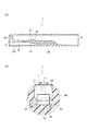
なお、端子3を端子収容室7内に収容した後には、図6に示すような検出部材53によって端子3の端子収容室7への収容状態及び導通状態が検出される。詳細には、検出部材53は、導通ピン55と検知ピン57とを有する。導通ピン55は、開口15から検出部材53が挿入されると、端子3の接続部5に当接され端子3の導通を検出する。検知ピン57は、開口15から検出部材53が挿入されると、係止ランス13の下面59と端子収容室7の下面59と対向する内壁面61との間に挿入される。このとき、図3に示すように、係止ランス13の係止部11と端子3の被係止部9とが正常に係合されている状態では、係止ランス13が上方に移動しているので、検知ピン57を下面59と内壁面61との間に挿入することができる。これに対し、係止ランス13の係止部11と端子3の被係止部9とが係合されていない状態では、係止ランス13が端子3の下面21によって下方に移動されているので、検知ピン57が係止ランス13の治具解除部47と当接してしまい、検知ピン57を下面59と内壁面61との間に挿入することができない。
In addition, after accommodating the terminal 3 in the
この検知ピン57の係止ランス13の下面59と端子収容室7の内壁面61との間への挿入の可否により、端子3の端子収容室7内における収容状態を検出することができる。また、検知ピン57を下面59と内壁面61との間に挿入することができない状態では、導通ピン55が端子3の接続部5と当接できないように設定されており、導通ピン55によっても端子3の端子収容室7内での異常を検出することができる。なお、検出部材53による端子3の状態の検出後には、係止ランス13の下面59と端子収容室7の内壁面61との間にスペーサなどの規制部材(不図示)が挿入され、係止ランス13の下方への撓みが規制され、係止部11と端子3の被係止部9との係合が解除されることが防止される。
Based on whether or not the detection pin 57 can be inserted between the
このように検知ピン57と係止ランス13の治具解除部47との当接によって端子3の異常を検出する構成では、係止ランス13の端子支持部27が係止部11から開口15に向けて延設されているので、検出部材53の検知ピン57を縮小することができ、検知ピン57の強度を向上することができる。この強度向上により、検知ピン57の厚みを薄くすることができ、検出部材53や係止ランス13の下面59と端子収容室7の内壁面61との間に挿入される規制部材を小型化することができる。
Thus, in the configuration in which the abnormality of the
このようなコネクタ1では、係止ランス13に係止部11から開口15に向けて延設され係止部11が被係止部9と係合した状態で一対の支持部23,25と共に端子3の下面21側を支持する端子支持部27が設けられているので、一対の支持部23,25の間で端子3を係止ランス13の端子支持部27によって支持することができ、端子3が一対の支持部23,25の間から脱落することを防止することができる。
In such a connector 1, the locking
従って、このようなコネクタ1では、端子収容室7内に端子3を安定して保持することができる。
Therefore, in such a connector 1, the
また、係止ランス13の端子支持部27は、係止部11から開口15に向けて延設されているので、端子収容室7内に端子3を収容した状態で、開口15から係止ランス13と端子収容室7との間に挿入される端子3の導通を検出する検出部材53や係止ランス13の係合状態を検出し係止ランスの撓みを規制する規制部材などの長さを縮小することができ、検出部材53や規制部材などの強度を向上することができる。このため、検出部材53や規制部材などの厚みも薄くすることができ、検出部材53や規制部材などを小型化することができる。
Further, since the
(第2実施形態)
図6を用いて第2実施形態について説明する。
(Second Embodiment)
A second embodiment will be described with reference to FIG.
本実施の形態に係るコネクタ101は、係止ランス103の下面59は、この下面59と対向する端子収容室7の内壁面61と略平行に形成されている。なお、第1実施形態と同一の構成には、同一の記号を記して説明を省略するが、第1実施形態と同一の構成であるので、構成及び機能説明は第1実施形態を参照するものとし省略するが、得られる効果は同一である。
In the
図6に示すように、係止ランス103の下面59は、係止部11が端子3の被係止部9と係合した状態で、下面59と対向する端子収容室7の内壁面61と略平行に形成されている。このように下面59を内壁面61と略平行に形成することにより、係止ランス103の下面59と端子収容室7の内壁面61との間の距離を縮小することができる。このため、係止ランス103の下面59と端子収容室7の内壁面61との間に挿入される検出部材53の検知ピン57や規制部材の厚みをさらに薄くすることができる。加えて、係止ランス103の下面59と端子収容室7の内壁面61との間の距離を縮小することができるので、コネクタ101のハウジング39を高さ方向に小型化することができる。
As shown in FIG. 6, the
なお、係止ランス103の下面59と端子収容室7の内壁面61との間の距離を縮小するために、係止ランス103の下面59を平行よりも僅かに開口15側に向けて下り傾斜となる傾斜面としてもよい。また、係止ランス103の端子支持部27の支持面49が僅かに傾斜面となっているが、係止部11が端子3の被係止部9と係合した状態で、端子3の下面21と同一面となるように支持面49を形成してもよい。
In order to reduce the distance between the
このようなコネクタ101では、係止ランス103の下面59がこの下面59と対向する端子収容室7の内壁面61と略平行に形成されているので、係止ランス103の下面59と端子収容室7の内壁面61との間の距離を、開口15から係止ランス103と端子収容室7との間に挿入される小型化された検出部材53や規制部材などに合わせて縮小することができ、コネクタ101全体を小型化することができる。
In such a
なお、本発明の実施の形態に係るコネクタでは、一対の支持部の支持面と端子支持部の支持面とが同一面となるように設定されているが、これに限らず、端子の下面側の形状に合わせて一対の支持部と端子支持部との支持面をそれぞれ設定すればよい。 In the connector according to the embodiment of the present invention, the support surface of the pair of support portions and the support surface of the terminal support portion are set to be the same surface. The support surfaces of the pair of support portions and the terminal support portion may be set in accordance with the shape of each.
1,101…コネクタ
3…端子
5…接続部
7…端子収容室
9…被係止部
11…係止部
13,103…係止ランス
15…開口
17,19…両側壁
21…端子の下面
23,25…支持部
27…端子支持部
59…係止ランスの下面
61…内壁面
DESCRIPTION OF SYMBOLS 1,101 ...
Claims (2)
前記係止ランスは、前記係止部から前記開口に向けて延設され前記係止部が前記被係止部と係合した状態で前記一対の支持部と共に前記端子の下面側を支持する端子支持部が設けられていることを特徴とするコネクタ。 A terminal housing chamber in which a terminal is accommodated and a connection portion side of the terminal is opened, and a locking lance provided with a locking portion that is flexibly provided in the terminal housing chamber and engages with a locked portion of the terminal. And a pair of support portions that are provided on both side walls on the opening side of the terminal accommodating chamber and support the lower surface sides on both sides in the width direction of the terminal,
The locking lance extends from the locking portion toward the opening, and supports the lower surface side of the terminal together with the pair of support portions in a state where the locking portion is engaged with the locked portion. A connector provided with a support portion.
前記係止ランスの下面は、この下面と対向する前記端子収容室の内壁面と略平行に形成されていることを特徴とするコネクタ。 The connector according to claim 1,
The connector is characterized in that the lower surface of the locking lance is formed substantially parallel to the inner wall surface of the terminal accommodating chamber facing the lower surface.
Priority Applications (1)
| Application Number | Priority Date | Filing Date | Title |
|---|---|---|---|
| JP2011063929A JP2012199189A (en) | 2011-03-23 | 2011-03-23 | Connector |
Applications Claiming Priority (1)
| Application Number | Priority Date | Filing Date | Title |
|---|---|---|---|
| JP2011063929A JP2012199189A (en) | 2011-03-23 | 2011-03-23 | Connector |
Publications (1)
| Publication Number | Publication Date |
|---|---|
| JP2012199189A true JP2012199189A (en) | 2012-10-18 |
Family
ID=47181192
Family Applications (1)
| Application Number | Title | Priority Date | Filing Date |
|---|---|---|---|
| JP2011063929A Abandoned JP2012199189A (en) | 2011-03-23 | 2011-03-23 | Connector |
Country Status (1)
| Country | Link |
|---|---|
| JP (1) | JP2012199189A (en) |
Cited By (3)
| Publication number | Priority date | Publication date | Assignee | Title |
|---|---|---|---|---|
| JP2015230857A (en) * | 2014-06-06 | 2015-12-21 | 矢崎総業株式会社 | connector |
| JP2016024903A (en) * | 2014-07-17 | 2016-02-08 | 矢崎総業株式会社 | connector |
| WO2021010364A1 (en) * | 2019-07-17 | 2021-01-21 | 住友電装株式会社 | Connector |
Citations (4)
| Publication number | Priority date | Publication date | Assignee | Title |
|---|---|---|---|---|
| JPS6396782U (en) * | 1986-12-12 | 1988-06-22 | ||
| JPH02162668A (en) * | 1988-09-26 | 1990-06-22 | Interlock Corp | Terminal assembly having |
| JPH07254449A (en) * | 1994-03-14 | 1995-10-03 | Sumitomo Wiring Syst Ltd | Connector and connector inspecting device |
| JP2009245634A (en) * | 2008-03-28 | 2009-10-22 | Yazaki Corp | Connector |
-
2011
- 2011-03-23 JP JP2011063929A patent/JP2012199189A/en not_active Abandoned
Patent Citations (4)
| Publication number | Priority date | Publication date | Assignee | Title |
|---|---|---|---|---|
| JPS6396782U (en) * | 1986-12-12 | 1988-06-22 | ||
| JPH02162668A (en) * | 1988-09-26 | 1990-06-22 | Interlock Corp | Terminal assembly having |
| JPH07254449A (en) * | 1994-03-14 | 1995-10-03 | Sumitomo Wiring Syst Ltd | Connector and connector inspecting device |
| JP2009245634A (en) * | 2008-03-28 | 2009-10-22 | Yazaki Corp | Connector |
Cited By (4)
| Publication number | Priority date | Publication date | Assignee | Title |
|---|---|---|---|---|
| JP2015230857A (en) * | 2014-06-06 | 2015-12-21 | 矢崎総業株式会社 | connector |
| JP2016024903A (en) * | 2014-07-17 | 2016-02-08 | 矢崎総業株式会社 | connector |
| WO2021010364A1 (en) * | 2019-07-17 | 2021-01-21 | 住友電装株式会社 | Connector |
| JP2021018852A (en) * | 2019-07-17 | 2021-02-15 | 住友電装株式会社 | connector |
Similar Documents
| Publication | Publication Date | Title |
|---|---|---|
| KR101567356B1 (en) | Electrical connector assembly, plug connector and receptacle connector | |
| JP2009206059A (en) | Electric connector | |
| JP2018018703A (en) | connector | |
| TWI435500B (en) | Joint connector and terminal half insert inspection method | |
| JP2010056084A (en) | Terminal position assuring member for electric connector | |
| JP5312528B2 (en) | Circuit board electrical connector and electrical connector assembly | |
| JP5682061B2 (en) | connector | |
| JP5753416B2 (en) | Connector terminal | |
| JP2012199189A (en) | Connector | |
| WO2012128283A1 (en) | Connector | |
| JP6322596B2 (en) | Connector with slider and connector fitting structure | |
| JP6187401B2 (en) | Connector and inspection jig | |
| JP2008152990A (en) | Connector and terminal metal fitting | |
| JP2008218198A (en) | Connector | |
| JP2018206511A (en) | connector | |
| US9196993B2 (en) | Connector unit | |
| US10461456B2 (en) | Connector | |
| JP6172760B2 (en) | Connector housing | |
| JP2013016359A (en) | Terminal fitting | |
| JP2012195106A (en) | Connector | |
| JP5594163B2 (en) | connector | |
| JP2010009801A (en) | Connector | |
| JP2008276993A (en) | Connector | |
| JP6323229B2 (en) | connector | |
| JP5731224B2 (en) | Combined connector and combined connector system |
Legal Events
| Date | Code | Title | Description |
|---|---|---|---|
| A621 | Written request for application examination |
Free format text: JAPANESE INTERMEDIATE CODE: A621 Effective date: 20140217 |
|
| A131 | Notification of reasons for refusal |
Free format text: JAPANESE INTERMEDIATE CODE: A131 Effective date: 20141125 |
|
| A762 | Written abandonment of application |
Free format text: JAPANESE INTERMEDIATE CODE: A762 Effective date: 20141219 |