JP2012199018A - Illumination device and display device - Google Patents
Illumination device and display device Download PDFInfo
- Publication number
- JP2012199018A JP2012199018A JP2011061292A JP2011061292A JP2012199018A JP 2012199018 A JP2012199018 A JP 2012199018A JP 2011061292 A JP2011061292 A JP 2011061292A JP 2011061292 A JP2011061292 A JP 2011061292A JP 2012199018 A JP2012199018 A JP 2012199018A
- Authority
- JP
- Japan
- Prior art keywords
- light guide
- case body
- illumination
- light
- display panel
- Prior art date
- Legal status (The legal status is an assumption and is not a legal conclusion. Google has not performed a legal analysis and makes no representation as to the accuracy of the status listed.)
- Withdrawn
Links
Images


Abstract
Description
本発明は、照明素子から発せられた照明光にて被照明部材を照明する照明装置及び表示装置に関するものである。 The present invention relates to an illumination device and a display device that illuminate a member to be illuminated with illumination light emitted from an illumination element.
従来より、発光ダイオード等の照明素子から発せられた照明光にて液晶表示パネルを照明する指針式計器が種々提案されており、例えば特許文献1に開示されている。この指針式計器は、表示器と、この表示器の周囲に位置する指標部を備えた表示板と、前記指標部を指示する指針と、前記表示部と前記指針とを導く導光体と、前記表示器の背面側に配置され、前記指針を回動させる駆動装置とを備えた構成であった。また、列状に設けられた照明素子群から発せられた光を導光体によって導光し、指針,液晶表示パネル及び表示板を照明する表示装置も知られている(特許文献2)。 Conventionally, various pointer-type meters for illuminating a liquid crystal display panel with illumination light emitted from an illumination element such as a light emitting diode have been proposed. This pointer-type meter includes a display, a display board provided with an indicator portion located around the indicator, a pointer that points to the indicator portion, a light guide that guides the display portion and the pointer, The driving device is disposed on the back side of the display and rotates the pointer. There is also known a display device that guides light emitted from a group of illumination elements provided in a row by a light guide to illuminate a pointer, a liquid crystal display panel, and a display plate (Patent Document 2).
しかしながら、前記表示装置は、ケース体に導光体を重ねるように配置した構造であり組み付け性は良いものの、フック係合などによって固定されていないため安定性に欠ける。また、ケース体と導光部材とに係合部と被係合部とを設ける必要があり、省スペース化には改善の余地があった。 However, the display device has a structure in which the light guide is placed on the case body and has good assemblability, but lacks stability because it is not fixed by hook engagement or the like. Moreover, it is necessary to provide an engaging part and an engaged part in the case body and the light guide member, and there is room for improvement in space saving.
本発明は、複数の照明素子からなる照明手段と、前記照明手段から発せられた照明光を被照明部材へ導く導光手段と、前記導光手段が収納されるケース体とを備え、
前記導光手段は、第一の導光体及び第二の導光体を有し、
前記照明手段は、前記第一の導光体に対応する第一の照明素子と、前記第二の導光体に対応する第二の照明素子とを有し、
前記導光手段は、前記第一の導光体と前記第二の導光体とを連結する連結部を有した照明装置であって、
前記導光手段は、突起部によってケース体に保持され、
前記ケース体は、前記導光手段と係合する係合部を有し、
前記突起部は、前記ケース体に設けられた嵌合孔に嵌合されるものである。
The present invention comprises an illuminating means comprising a plurality of illuminating elements, a light guiding means for guiding illumination light emitted from the illuminating means to an illuminated member, and a case body in which the light guiding means is accommodated.
The light guide means has a first light guide and a second light guide,
The illumination means has a first illumination element corresponding to the first light guide and a second illumination element corresponding to the second light guide,
The light guide means is a lighting device having a connecting portion for connecting the first light guide and the second light guide,
The light guiding means is held in the case body by a protrusion,
The case body has an engaging portion that engages with the light guide means,
The protrusion is fitted into a fitting hole provided in the case body.
また、本発明は、前記連結部は、U字状またはコ字状の折れ曲がり部を有するものである。 In the present invention, the connecting portion has a U-shaped or U-shaped bent portion.
また、本発明は、前記ケース体は、前記第一の導光体と前記第二の導光体とを区画する遮光壁を備えたものである。 In the present invention, the case body includes a light shielding wall that partitions the first light guide and the second light guide.
また、本発明は、液晶表示パネルと、表示板と、前記液晶表示パネル及び前記表示板を照明する複数の照明素子からなる照明手段と、前記照明手段から発せられた照明光を被照明部材へ導く導光手段と、前記導光手段が収納されるケース体とを備え、
前記導光手段が突起部によってケース体に保持され、
前記導光手段は、第一の導光体及び第二の導光体を有し、
前記照明手段は、前記第一の導光体に対応する第一の照明素子と、前記第二の導光体に対応する第二の照明素子とを有し、
前記導光手段は、前記第一の導光体と前記第二の導光体とを連結する連結部を有した表示装置であって、
前記導光手段は、突起部によってケース体に保持され、
前記ケース体は、前記導光手段と係合する係合部を有し、
前記突起部は、前記ケース体に設けられた嵌合孔に嵌合されるものである。
In addition, the present invention provides a liquid crystal display panel, a display plate, an illuminating unit including a plurality of illumination elements that illuminate the liquid crystal display panel and the display plate, and illumination light emitted from the illuminating unit to an illuminated member. A light guide means for guiding, and a case body in which the light guide means is housed,
The light guiding means is held in the case body by a protrusion,
The light guide means has a first light guide and a second light guide,
The illumination means has a first illumination element corresponding to the first light guide and a second illumination element corresponding to the second light guide,
The light guide means is a display device having a connecting portion for connecting the first light guide and the second light guide,
The light guiding means is held in the case body by a protrusion,
The case body has an engaging portion that engages with the light guide means,
The protrusion is fitted into a fitting hole provided in the case body.
導光手段をケース体に位置決めすることができるため、安定性が向上した照明装置及び表示装置を提供することができる。 Since the light guide means can be positioned on the case body, an illumination device and a display device with improved stability can be provided.
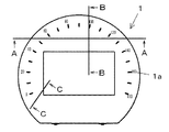
以下、添付図面に基づいて、本発明の一実施形態を説明する。表示装置は、表示板(被照明部材)1と、カバー体2と、液晶表示パネル(被照明部材)3と、第一,第二の導光体4a、4bからなる導光体4と、ケース体5と、第一,第二の照明素子6a、6bからなる照明素子6と、回路基板7とから主に構成されている。
Hereinafter, an embodiment of the present invention will be described with reference to the accompanying drawings. The display device includes a display panel (illuminated member) 1, a
表示板1は、透明樹脂に指標部1aとなる数字及び目盛りを印刷したものであり、第二の導光体4bの前面(表示面側)に配置され、第二の導光体4bより照射される光を透過させ、指標部1aが光輝する。
The
カバー体2は、白色の合成樹脂からなり、ケース体5に嵌合し、表示板1、第1、第2の導光体4a、4bをケース体5に固定する。カバー体2は、後述するコ字状の連結部41が形成する凹部に位置する凸部(遮光部)21を有している。カバー体2の凸部21により、第一,第二の導光体4a、4bから進入する光のうち、第一、第二の導光体4a、4bの間のお互いに干渉する光(連結部41を介さない光)を遮ることができ、輝度ムラや色ムラの発生を抑制できる。
The
液晶表示パネル3は、STN(Super Twisted Nematic)やTN(Twisted Nematic)等の液晶表示素子であり、第一の導光体5の前方に配置され、様々な情報(外気温情報,走行距離情報,燃費情報,ナビゲーション情報等)を表示する。液晶表示パネル3には、可撓性配線板31が接続されている。光拡散シート32は、薄い板状の透光性樹脂からなり、液晶表示パネル3の後面に配設され、第一の導光体4aから出射される光を拡散させ、照明ムラを緩和させる。
The liquid
第一の導光体4aは、第一の照明素子6aから発せられた光を液晶表示パネル3に向けて導光し、液晶表示パネル3を透過照明する。第一の導光体4aの後面(裏面)には、微細な溝、あるいはドット等が形成されており、液晶表示パネル3に向けて、照明ムラの無い導光を可能としている。
The first light guide 4a guides light emitted from the
第二の導光体4bは、第二の照明素子6bから発せられた光を表示板1に向けて導光し、表示板1を透過照明する。第二の導光体4bの裏面には、微細な溝、あるいはドット等が形成されており、表示板1に向けて、照明ムラの無い導光を可能としている。
The
図6に示すように、第一の導光体4aと第二の導光体4bとの間には空隙部42が形成されており、この空隙部42によって第一,第二の導光体4a、4bへの導光経路を分断し、相互が照明的な干渉を抑制し、第一,第二の照明素子6a、6bが発した光を夫々液晶表示パネル3,表示板1に導光することを可能にしている。
As shown in FIG. 6, a gap 42 is formed between the first light guide 4 a and the
第一の導光体4aと第二の導光体4bは、連結部41によって連結され、一体となっている。連結部41の表面は、粗面になっている。連結部41はコ字状の折れ曲がり部411を有しており、この折れ曲がり部411は分岐部412を有している。折れ曲がり部411に分岐部412を設けたことにより、折れ曲がり部411における導光経路を分岐することで、輝度ムラあるいは色ムラの原因となる導光体4a,4bへの光の進入を低減することができる。
The 1st light guide 4a and the
また、連結部41及び空隙部42には、後述するケース体5に形成された位置決め孔52に挿入される位置決め部43が3つ突出成形され、位置決め部43と位置決め孔52とが嵌め合わされることによって、導光体4がケース体5に保持されている。
Further, three positioning
ケース体5は、白色樹脂からなるものであり、第一,第二の導光体4a,4b,回路基板7等を保持する。ケース体5は、第一,第二の導光体4a,4bの背後に配設され、第一,第二の導光体4a,4bからの漏光を反射させることにより、導光効率を上昇させる。ケース体5には、第一、第二の導光体4a、4bを区画するように遮光壁が一体成形されていることにより、第一、第二の照明素子6a、6bが色混ざりなどしないで各々照明可能となる。
The
また、ケース体5には、連結部41と係合するためのフックからなる係合部53が、連結部41と対応する箇所に一体成形されていることにより、ケース体5に被係合部を設けることなく、導光体4をケース体5に係合することができる。
Further, the
回路基板7は、アルミ等の高熱伝導率の材質からなり、第一,第二の照明素子6a、6bと電気的に接続され、第一,第二の照明素子6a、6bに電力を供給する。
The
第一の照明素子6aは、チップ型発光ダイオードからなり、第一の導光体4aの端面44から第一の導光体4aの内部に光を供給できるように配設される。第一の照明素子6aは回路基板7から供給される電力によって発光し、第一の導光体4aを介して、液晶表示パネル3を透過照明する。
The
第二の照明素子6bは、チップ型発光ダイオードからなり、第二の導光体4bの端面45から第二の導光体4bの内部に光を供給できるように配設される。第二の照明素子6bは回路基板7から供給される電力によって発光し、第二の導光体4bを介して、表示板1を透過照明する。
The
第一の照明素子6a及び第二の照明素子6bは、回路基板7に搭載され、列状に配置されている。第一,第二の照明素子6a,6bは、輝度を独立で調光したり、あるいは発光色を夫々で変えたりすることができ、第二の照明素子6bは、第一の照明素子6aとは異なる輝度、もしくは異なる色を発する。
The
本実施形態のように、複数の照明素子からなる照明手段6と、照明手段6から発せられた照明光を被照明部材へ導く導光体4と、導光体4が収納されるケース体5とを備え、
導光体4は、第一の導光体4a及び第二の導光体4bを有し、
照明手段6は、第一の導光体4aに対応する第一の照明素子6aと、第二の導光体4bに対応する第二の照明素子6bとを有し、
導光体4は、第一の導光体4aと第二の導光体4bとを連結する連結部41を有した照明装置であって、
導光体4は、位置決め部43によってケース体5に保持され、
ケース体5は、導光手段と係合する係合部53を有し、
位置決め部43は、ケース体5に設けられた位置決め孔52に嵌合されることによって、導光体4をケース体5に位置決めすることができるため、安定性が向上した表示装置を提供することができる。
Like this embodiment, the illumination means 6 which consists of a some illumination element, the
The
The illumination means 6 has a
The
The
The
Since the
なお、本発明は、各実施形態に限定されるものではなく、種々の変形が可能であり、例えば、連結部41はコ字状であったが、U字状であっても良い。
In addition, this invention is not limited to each embodiment, A various deformation | transformation is possible, for example, although the
1 表示板
1a 指標部
2 カバー体
3 液晶表示パネル
4 導光体(導光手段)
4a 第一の導光体
4b 第二の導光体
5 ケース体
6 照明素子(照明手段)
6a 第一の照明素子
6b 第二の照明素子
7 回路基板
31 可撓性配線板
41 連結部
42 空隙部
43 位置決め部(突起部)
51 遮光壁
52 位置決め孔(嵌合孔)
53 係合部
DESCRIPTION OF
4 Light guide (light guide means)
4a First
6a
51
53 engaging part
Claims (4)
前記導光手段は、第一の導光体及び第二の導光体を有し、
前記照明手段は、前記第一の導光体に対応する第一の照明素子と、前記第二の導光体に対応する第二の照明素子とを有し、
前記導光手段は、前記第一の導光体と前記第二の導光体とを連結する連結部を有した照明装置であって、
前記導光手段は、突起部によってケース体に保持され、
前記ケース体は、前記導光手段と係合する係合部を有し、
前記突起部は、前記ケース体に設けられた嵌合孔に嵌合されることを特徴とする照明装置。 Illuminating means comprising a plurality of illumination elements, light guide means for guiding illumination light emitted from the illumination means to an illuminated member, and a case body in which the light guide means is housed,
The light guide means has a first light guide and a second light guide,
The illumination means has a first illumination element corresponding to the first light guide and a second illumination element corresponding to the second light guide,
The light guide means is a lighting device having a connecting portion for connecting the first light guide and the second light guide,
The light guiding means is held in the case body by a protrusion,
The case body has an engaging portion that engages with the light guide means,
The projection device is fitted in a fitting hole provided in the case body.
前記照明手段は、前記第一の導光体に対応する第一の照明素子と、前記第二の導光体に対応する第二の照明素子とを有し、
前記導光手段は、前記第一の導光体と前記第二の導光体とを連結する連結部を有した表示装置であって、
前記導光手段は、突起部によってケース体に保持され、
前記ケース体は、前記導光手段と係合する係合部を有し、
前記突起部は、前記ケース体に設けられた嵌合孔に嵌合されることを特徴とする表示装置。
A liquid crystal display panel; a display panel; an illuminating unit comprising a plurality of illumination elements that illuminate the liquid crystal display panel and the display panel; a light guiding unit that guides illumination light emitted from the illuminating unit to an illuminated member; A case body in which the light guide means is housed, and the light guide means includes a first light guide and a second light guide,
The illumination means has a first illumination element corresponding to the first light guide and a second illumination element corresponding to the second light guide,
The light guide means is a display device having a connecting portion for connecting the first light guide and the second light guide,
The light guiding means is held in the case body by a protrusion,
The case body has an engaging portion that engages with the light guide means,
The display device, wherein the protrusion is fitted into a fitting hole provided in the case body.
Priority Applications (1)
| Application Number | Priority Date | Filing Date | Title |
|---|---|---|---|
| JP2011061292A JP2012199018A (en) | 2011-03-18 | 2011-03-18 | Illumination device and display device |
Applications Claiming Priority (1)
| Application Number | Priority Date | Filing Date | Title |
|---|---|---|---|
| JP2011061292A JP2012199018A (en) | 2011-03-18 | 2011-03-18 | Illumination device and display device |
Publications (1)
| Publication Number | Publication Date |
|---|---|
| JP2012199018A true JP2012199018A (en) | 2012-10-18 |
Family
ID=47181070
Family Applications (1)
| Application Number | Title | Priority Date | Filing Date |
|---|---|---|---|
| JP2011061292A Withdrawn JP2012199018A (en) | 2011-03-18 | 2011-03-18 | Illumination device and display device |
Country Status (1)
| Country | Link |
|---|---|
| JP (1) | JP2012199018A (en) |
-
2011
- 2011-03-18 JP JP2011061292A patent/JP2012199018A/en not_active Withdrawn
Similar Documents
| Publication | Publication Date | Title |
|---|---|---|
| CN103443593B (en) | Indicator member, indicator unit and indicator instrument | |
| US8931912B2 (en) | Display illumination structure | |
| JP4931985B2 (en) | Backlight unit and display using the same | |
| JP4434120B2 (en) | Light source device | |
| JP2011047790A (en) | Display device | |
| US9108565B2 (en) | Lighting structure of liquid crystal panel in gauge for vehicle | |
| JP2010054358A (en) | Pointer type measuring instrument | |
| JP5668833B2 (en) | Lighting device | |
| JP5999411B2 (en) | Luminescent display device | |
| JP5495049B2 (en) | Lighting device and display device | |
| JP5510076B2 (en) | Display device | |
| JP6232670B2 (en) | Dial illumination structure | |
| JP6150607B2 (en) | Light emitting device | |
| JP2012199018A (en) | Illumination device and display device | |
| JP2010107463A (en) | Illumination device | |
| JP2011248113A (en) | Liquid crystal display device | |
| WO2011093159A1 (en) | Indicator device | |
| JP2012073220A (en) | Instrument device | |
| JP3182212U (en) | Illuminated display device | |
| JP6195106B2 (en) | Lighting device | |
| JP5243291B2 (en) | Lighting device | |
| JP2009198461A (en) | Lighting structure for vehicular meter | |
| JP2016008947A (en) | Display device | |
| JP3611262B2 (en) | Lighting device for vehicle instrument | |
| JP5885024B2 (en) | Display device |
Legal Events
| Date | Code | Title | Description |
|---|---|---|---|
| A300 | Withdrawal of application because of no request for examination |
Free format text: JAPANESE INTERMEDIATE CODE: A300 Effective date: 20140603 |