JP2012198207A - Image processing device and method, and mobile-body collision prevention apparatus - Google Patents
Image processing device and method, and mobile-body collision prevention apparatus Download PDFInfo
- Publication number
- JP2012198207A JP2012198207A JP2012060124A JP2012060124A JP2012198207A JP 2012198207 A JP2012198207 A JP 2012198207A JP 2012060124 A JP2012060124 A JP 2012060124A JP 2012060124 A JP2012060124 A JP 2012060124A JP 2012198207 A JP2012198207 A JP 2012198207A
- Authority
- JP
- Japan
- Prior art keywords
- imaging
- image
- image processing
- focusing
- images
- Prior art date
- Legal status (The legal status is an assumption and is not a legal conclusion. Google has not performed a legal analysis and makes no representation as to the accuracy of the status listed.)
- Granted
Links
- 238000012545 processing Methods 0.000 title claims abstract description 112
- 230000002265 prevention Effects 0.000 title claims abstract description 23
- 238000000034 method Methods 0.000 title claims abstract description 13
- 238000003384 imaging method Methods 0.000 claims abstract description 160
- 238000009826 distribution Methods 0.000 claims abstract description 73
- 230000007246 mechanism Effects 0.000 claims abstract description 29
- 230000008859 change Effects 0.000 claims abstract description 15
- 230000003287 optical effect Effects 0.000 claims abstract description 11
- 238000001514 detection method Methods 0.000 claims description 12
- 230000008569 process Effects 0.000 claims description 6
- 238000003672 processing method Methods 0.000 claims description 4
- 230000000295 complement effect Effects 0.000 claims description 3
- 229910044991 metal oxide Inorganic materials 0.000 claims description 3
- 150000004706 metal oxides Chemical class 0.000 claims description 3
- 239000004065 semiconductor Substances 0.000 claims description 3
- 238000004904 shortening Methods 0.000 claims description 2
- 238000010586 diagram Methods 0.000 description 8
- 230000006870 function Effects 0.000 description 5
- 239000003550 marker Substances 0.000 description 5
- 230000003247 decreasing effect Effects 0.000 description 2
- 230000000694 effects Effects 0.000 description 2
- 238000005516 engineering process Methods 0.000 description 2
- 230000002452 interceptive effect Effects 0.000 description 2
- 238000004519 manufacturing process Methods 0.000 description 2
- 238000005259 measurement Methods 0.000 description 2
- 238000012544 monitoring process Methods 0.000 description 2
- 235000004522 Pentaglottis sempervirens Nutrition 0.000 description 1
- 230000001133 acceleration Effects 0.000 description 1
- 238000013459 approach Methods 0.000 description 1
- 238000004364 calculation method Methods 0.000 description 1
- 239000003086 colorant Substances 0.000 description 1
- 238000005286 illumination Methods 0.000 description 1
- 238000012986 modification Methods 0.000 description 1
- 230000004048 modification Effects 0.000 description 1
- 238000012806 monitoring device Methods 0.000 description 1
- 230000009467 reduction Effects 0.000 description 1
- 230000004044 response Effects 0.000 description 1
- 238000006467 substitution reaction Methods 0.000 description 1
- 239000002023 wood Substances 0.000 description 1
Images


Classifications
-
- G—PHYSICS
- G08—SIGNALLING
- G08G—TRAFFIC CONTROL SYSTEMS
- G08G1/00—Traffic control systems for road vehicles
- G08G1/16—Anti-collision systems
- G08G1/166—Anti-collision systems for active traffic, e.g. moving vehicles, pedestrians, bikes
-
- G—PHYSICS
- G06—COMPUTING; CALCULATING OR COUNTING
- G06V—IMAGE OR VIDEO RECOGNITION OR UNDERSTANDING
- G06V20/00—Scenes; Scene-specific elements
- G06V20/50—Context or environment of the image
- G06V20/56—Context or environment of the image exterior to a vehicle by using sensors mounted on the vehicle
- G06V20/58—Recognition of moving objects or obstacles, e.g. vehicles or pedestrians; Recognition of traffic objects, e.g. traffic signs, traffic lights or roads
-
- G—PHYSICS
- G08—SIGNALLING
- G08G—TRAFFIC CONTROL SYSTEMS
- G08G1/00—Traffic control systems for road vehicles
- G08G1/16—Anti-collision systems
- G08G1/165—Anti-collision systems for passive traffic, e.g. including static obstacles, trees
-
- H—ELECTRICITY
- H04—ELECTRIC COMMUNICATION TECHNIQUE
- H04N—PICTORIAL COMMUNICATION, e.g. TELEVISION
- H04N23/00—Cameras or camera modules comprising electronic image sensors; Control thereof
- H04N23/60—Control of cameras or camera modules
- H04N23/63—Control of cameras or camera modules by using electronic viewfinders
-
- H—ELECTRICITY
- H04—ELECTRIC COMMUNICATION TECHNIQUE
- H04N—PICTORIAL COMMUNICATION, e.g. TELEVISION
- H04N23/00—Cameras or camera modules comprising electronic image sensors; Control thereof
- H04N23/60—Control of cameras or camera modules
- H04N23/67—Focus control based on electronic image sensor signals
-
- H—ELECTRICITY
- H04—ELECTRIC COMMUNICATION TECHNIQUE
- H04N—PICTORIAL COMMUNICATION, e.g. TELEVISION
- H04N23/00—Cameras or camera modules comprising electronic image sensors; Control thereof
- H04N23/70—Circuitry for compensating brightness variation in the scene
- H04N23/743—Bracketing, i.e. taking a series of images with varying exposure conditions
-
- B—PERFORMING OPERATIONS; TRANSPORTING
- B60—VEHICLES IN GENERAL
- B60R—VEHICLES, VEHICLE FITTINGS, OR VEHICLE PARTS, NOT OTHERWISE PROVIDED FOR
- B60R2300/00—Details of viewing arrangements using cameras and displays, specially adapted for use in a vehicle
- B60R2300/80—Details of viewing arrangements using cameras and displays, specially adapted for use in a vehicle characterised by the intended use of the viewing arrangement
- B60R2300/8093—Details of viewing arrangements using cameras and displays, specially adapted for use in a vehicle characterised by the intended use of the viewing arrangement for obstacle warning
Abstract
Description
本発明は、画像処理装置、例えば画像処理による移動体衝突防止装置に関するものである。本発明はまた、そのような画像処理方法にも関する。 The present invention relates to an image processing apparatus, for example, a moving object collision preventing apparatus using image processing. The present invention also relates to such an image processing method.
特開2000-304856号公報(特許文献1)および特開平11-120499号公報(特許文献2)には、飛行機または船舶に搭載される全地球測位システム(GPS)またはレーダを利用した衝突防止装置が記載されている。特許第3260645号公報(特許文献3)には、車両等の地上輸送装置に搭載されるGPSを利用したカーナビゲーション装置が記載されている。また、特開2001-337724号公報(特許文献4)には、GPSを利用して無人車両が特定の領域に進入することを防止する技術が記載されている。さらに、特開平5-143158号公報(特許文献5)には、ワイヤレス監視デバイスにより無人車両同士の衝突を防止する技術が記載されている。 Japanese Patent Laid-Open No. 2000-304856 (Patent Document 1) and Japanese Patent Laid-Open No. 11-120499 (Patent Document 2) disclose a global positioning system (GPS) mounted on an airplane or ship or a collision prevention device using a radar. Is described. Japanese Patent No. 3260645 (Patent Document 3) describes a car navigation device using GPS mounted on a ground transportation device such as a vehicle. Japanese Unexamined Patent Publication No. 2001-337724 (Patent Document 4) describes a technique for preventing an unmanned vehicle from entering a specific area using GPS. Furthermore, Japanese Patent Laid-Open No. 5-143158 (Patent Document 5) describes a technique for preventing a collision between unmanned vehicles using a wireless monitoring device.
近年、GPS受信機、速度検出部および方向検出部を有する移動体衝突防止装置において、上述の各構成要素により獲得されたGPS位置情報、速度情報および方向情報を他の移動体へ送信することにより、これらの情報を受信した移動体は衝突が発生するか否かを判断できる。 In recent years, in a mobile collision prevention apparatus having a GPS receiver, a speed detection unit, and a direction detection unit, by transmitting GPS position information, speed information, and direction information acquired by the above-described components to other mobile units The mobile body that has received these pieces of information can determine whether or not a collision occurs.
しかし、このようなGPSを利用した従来技術では、GPS自体の測定精度およびGPS受信設備の精度により、移動体同士の相互間距離の計算における誤差は通常数メートル(m)ないし十数メートルほどに及ぶことがある。したがって、衝突事故が起こり得る近距離の範囲内で、移動体の位置を誤って検出する恐れがある。 However, in the conventional technology using such GPS, the error in the calculation of the distance between the moving bodies is usually several meters (m) to several tens of meters due to the measurement accuracy of the GPS itself and the accuracy of the GPS receiving equipment. There may be. Therefore, there is a possibility that the position of the moving body is erroneously detected within a short range where a collision accident may occur.
本発明は、このような従来技術における問題点を鑑みて、近距離範囲で物体を正確に認識できる画像処理装置および方法、ならびに移動体衝突防止装置を提供することを目的としている。 An object of the present invention is to provide an image processing apparatus and method capable of accurately recognizing an object in a short distance range, and a moving object collision preventing apparatus in view of such problems in the conventional technology.
本発明による画像処理装置は、撮像手段と、該撮像手段が撮像した画像を処理する画像処理手段とを備え、前記撮像手段は、撮像レンズと、該撮像レンズを駆動しフォーカシング距離を変更する合焦機構と、撮像素子とを有し、該合焦機構は、前記撮像レンズを駆動して該撮像レンズの光軸方向における異なる位置の物体を前記撮像素子に鮮明に結像させるように順次フォーカシング距離を変更するフォーカススイープを行い、前記撮像手段は、前記フォーカススイープにおいて複数の異なるフォーカシング距離に応じてそれぞれ画像を撮像し、前記画像処理手段は、前記撮像された複数枚の画像から、該複数枚の画像のそれぞれにおいて鮮明に結像された物体を認識し、該複数枚の画像のそれぞれの撮像時のフォーカシング距離に対応して前記認識された物体の位置を表示する物体分布画像を生成することを特徴とする。 An image processing apparatus according to the present invention includes an imaging unit and an image processing unit that processes an image captured by the imaging unit. The imaging unit drives the imaging lens and the focusing lens to change a focusing distance. A focusing mechanism and an imaging device, and the focusing mechanism sequentially focuses so as to drive the imaging lens to clearly image an object at a different position in the optical axis direction of the imaging lens on the imaging device. A focus sweep for changing a distance is performed, and the imaging unit captures images according to a plurality of different focusing distances in the focus sweep, and the image processing unit is configured to detect the plurality of images from the plurality of captured images. Recognize the clearly imaged object in each of the images, and correspond to the focusing distance at the time of capturing each of the images And generating an object distribution picture to see the position of the serial recognized objects.
本発明の画像処理装置によれば、撮像範囲内における物体の分布を示す画像が生成される。この物体分布画像は、生産現場における設備の位置識別および監視制御、スポーツ試合の生中継における視角の切替え、インタラクティブな娯楽システム、および後記の本願発明に係る移動体衝突防止装置に適用することができる。 According to the image processing apparatus of the present invention, an image showing the distribution of objects within the imaging range is generated. This object distribution image can be applied to equipment location identification and monitoring control at a production site, viewing angle switching in live sports games, an interactive entertainment system, and a mobile collision prevention apparatus according to the present invention described later. .
また、本発明による画像処理装置において、前記フォーカススイープにおいて、フォーカシング距離は1m以下のステップ幅で変化させることが望ましい。これにより、物体分布画像の精密度を向上させることができる。 In the image processing apparatus according to the present invention, it is desirable that the focusing distance is changed with a step width of 1 m or less in the focus sweep. Thereby, the precision of an object distribution image can be improved.
また、本発明による画像処理装置において、前記撮像手段は500画像/秒以上の頻度で撮像することが望ましい。これにより、よりリアルタイムに物体分布画像を生成することができる。 In the image processing apparatus according to the present invention, it is preferable that the imaging unit captures images at a frequency of 500 images / second or more. Thereby, an object distribution image can be generated in more real time.
また、本発明による画像処理装置において、前記撮像手段は前記フォーカススイープを繰り返して複数回行い、前記画像処理手段は、該複数回のフォーカススイープに対応して前記物体分布画像を複数枚生成することが望ましい。フォーカススイープを繰返し行うことにより、物体分布画像を随時に更新し、物体分布画像の実時間性をさらに向上ることができる。 In the image processing apparatus according to the present invention, the imaging unit repeatedly performs the focus sweep a plurality of times, and the image processing unit generates a plurality of the object distribution images corresponding to the plurality of focus sweeps. Is desirable. By repeatedly performing the focus sweep, the object distribution image can be updated as needed, and the real-time property of the object distribution image can be further improved.
また、本発明による画像処理装置において、前記撮像手段は前記フォーカススイープを毎秒5回以上行うことが望ましい。これにより、物体分布画像を更新する実時間性をさらに向上させることができる。 In the image processing apparatus according to the present invention, it is preferable that the imaging unit performs the focus sweep five times or more per second. Thereby, the real time property which updates an object distribution image can further be improved.
また、本発明による画像処理装置において、前記撮像手段は電荷結合デバイス(CCD)センサまたは相補型金属酸化膜半導体(CMOS)を利用することができ、また、赤外線撮像素子を利用してもよい。撮像素子は、使用する環境に適した種類を選択することができる。 In the image processing apparatus according to the present invention, the image pickup means may use a charge coupled device (CCD) sensor or a complementary metal oxide semiconductor (CMOS), or may use an infrared image pickup device. As the imaging device, a type suitable for an environment to be used can be selected.
また、本発明による画像処理装置において、前記撮像レンズはズームレンズを含み、前記撮像手段は、該ズームレンズを駆動しその焦点距離を変更するズーミング機構を備え、該ズーミング機構は、前記フォーカシング距離が所定値より長くなるとき、前記ズームレンズを駆動してその焦点距離を長くし、前記フォーカシング距離が所定値より短くなるとき、前記ズームレンズを駆動してその焦点距離を短くすることが望ましい。 In the image processing apparatus according to the present invention, the imaging lens includes a zoom lens, and the imaging unit includes a zooming mechanism that drives the zoom lens and changes a focal distance thereof, and the zooming mechanism has the focusing distance. When the zoom lens is longer than a predetermined value, it is desirable to drive the zoom lens to increase its focal length, and when the focusing distance is shorter than a predetermined value, it is preferable to drive the zoom lens to shorten the focal length.
また、本発明による画像処理方法は、撮像レンズ、該撮像レンズを駆動しフォーカシング距離を変更する合焦機構、および撮像素子を有する撮像手段と、該撮像手段が撮像した画像を処理する画像処理手段とを備える画像処理装置において、前記撮像手段において、前記合焦機構は、前記撮像レンズを駆動して該撮像レンズの光軸方向における異なる位置の物体を前記撮像素子に鮮明に結像させるように順次フォーカシング距離を変更するフォーカススイープを行い、該フォーカススイープにおいて複数の異なるフォーカシング距離に応じてそれぞれの画像を撮像し、前記画像処理手段において、前記撮像された複数枚の画像から、該複数枚の画像のそれぞれにおいて鮮明に結像された物体を認識し、該複数枚の画像のそれぞれの撮像時のフォーカシング距離に応じて前記認識された物体の位置を表示する物体分布画像を生成することを特徴とする。 An image processing method according to the present invention includes an imaging lens, a focusing mechanism that drives the imaging lens to change a focusing distance, an imaging unit having an imaging element, and an image processing unit that processes an image captured by the imaging unit. In the image processing apparatus, in the imaging unit, the focusing mechanism drives the imaging lens so that objects at different positions in the optical axis direction of the imaging lens are clearly imaged on the imaging element. A focus sweep that sequentially changes the focusing distance is performed, and each image is captured according to a plurality of different focusing distances in the focus sweep, and the plurality of captured images are picked up from the captured plurality of images by the image processing means. Recognizes a clearly imaged object in each of the images, and captures each of the plurality of images at the time of imaging. And generating an object distribution image displaying the position of the recognized object in accordance with the Kashingu distance.
本発明の画像処理方法において、前記撮像手段は、前記フォーカススイープを繰り返して複数回行い、前記画像処理手段は、該複数回のフォーカススイープに応じて前記物体分布画像を複数枚生成することが望ましい。 In the image processing method according to the aspect of the invention, it is preferable that the imaging unit repeatedly performs the focus sweep a plurality of times, and the image processing unit generates a plurality of the object distribution images according to the plurality of focus sweeps. .
本発明による移動体衝突防止装置は移動体に設けられ、該移動体の周囲を撮像する撮像手段と、該撮像手段が撮像した画像を処理する画像処理手段と、衝突判定手段とを備え、前記撮像手段は、撮像レンズと、該撮像レンズを駆動してフォーカシング距離を変更する合焦機構と、撮像素子とを有し、該合焦機構は、前記撮像レンズを駆動して、前記移動体から離れている複数の物体を前記撮像素子に鮮明に結像させるように順次フォーカシング距離を変更するフォーカススイープを行い、前記撮像手段は、該フォーカススイープにおいて複数の異なるフォーカシング距離に応じてそれぞれの画像を撮像し、前記画像処理手段は、前記撮像された複数枚の画像から、該複数枚の画像のそれぞれにおいて鮮明に結像された物体を認識し、該複数枚の画像のそれぞれの撮像時のフォーカシング距離に対応して前記認識された物体の位置を表示する物体分布画像を生成し、前記衝突判定手段は、該物体分布画像に基づいて前記移動体と前記認識された物体とが衝突するか否かを判定することを特徴とする。 A moving object collision preventing apparatus according to the present invention is provided on a moving object, and includes an imaging unit that images the periphery of the moving object, an image processing unit that processes an image captured by the imaging unit, and a collision determination unit, The imaging means includes an imaging lens, a focusing mechanism that drives the imaging lens to change a focusing distance, and an imaging element. The focusing mechanism drives the imaging lens to move from the moving body. A focus sweep is performed to sequentially change a focusing distance so that a plurality of distant objects are clearly imaged on the image sensor, and the imaging unit displays each image according to a plurality of different focusing distances in the focus sweep. The image processing means recognizes an object that is clearly imaged in each of the plurality of images from the plurality of captured images, and the plurality of images An object distribution image that displays a position of the recognized object corresponding to a focusing distance at the time of capturing each of the images is generated, and the collision determination unit recognizes the moving object based on the object distribution image. It is characterized by determining whether or not the object collides.
本発明の移動体衝突防止装置によれば、衝突判定手段が、画像処理手段で生成される物体分布画像により衝突を判断することにより、効果的に移動体の衝突事故を回避することができる。 According to the mobile object collision preventing apparatus of the present invention, the collision determination unit can effectively avoid the collision accident of the mobile object by determining the collision from the object distribution image generated by the image processing unit.
また、本発明の移動体衝突防止装置は、物体分布画像を表示する表示手段を有し、前記衝突判定手段は、前記移動体と前記認識された物体とが衝突すると判定すると、前記表示手段は、該物体を異なる色で表示する。また、移動体の操縦者に通知する通知手段を備え、前記衝突判定手段は、前記移動体と前記認識された物体とが衝突すると判定すると、前記通知手段は前記操縦者へ警告メッセージを発生する。さらに、前記物体分布画像を表示する表示手段を有し、前記画像処理手段は、該物体分布画像に距離の間隔を表す格子線の表示を加えることが望ましい。 The moving body collision preventing apparatus of the present invention has display means for displaying an object distribution image, and when the collision determination means determines that the moving body and the recognized object collide, the display means , Display the object in different colors. In addition, a notification means for notifying a pilot of a mobile object is provided, and when the collision determination means determines that the mobile object and the recognized object collide, the notification means generates a warning message to the pilot. . Furthermore, it is preferable that display means for displaying the object distribution image is provided, and the image processing means adds display of grid lines representing distance intervals to the object distribution image.
以上により、衝突判定手段が衝突すると判断した場合、表示手段または通知手段は、迅速に移動体の操縦者や車両の運転者に警告し、衝突を対応するように促す。これにより、衝突事故を回避することができる。 As described above, when the collision determination unit determines that a collision occurs, the display unit or the notification unit promptly warns the driver of the moving body or the driver of the vehicle and prompts the collision to be dealt with. Thereby, a collision accident can be avoided.
また、本発明の移動体衝突防止装置は、前記移動体の移動を制御する移動体制御手段を備え、該移動体と前記認識された物体とが衝突すると前記衝突判定手段が判定すると、前記移動体制御手段は、前記移動体のブレーキ、アクセル、または操舵を制御することが望ましい。こうして、移動体制御手段により移動体を操縦し、衝突事故を回避し、また自動走行を実現することができる。 The moving object collision preventing apparatus of the present invention further includes moving object control means for controlling the movement of the moving object, and the movement determining means determines that the moving object and the recognized object collide with each other. It is desirable that the body control means controls the brake, accelerator or steering of the moving body. In this way, it is possible to steer the moving body by the moving body control means, avoid a collision accident, and realize automatic traveling.
また、本発明の移動体衝突防止装置は、前記移動体の速度を検出する速度検出手段を備え、前記衝突判定手段は、該速度検出手段が検出した前記移動体の速度から、該移動体と前記認識された物体とが衝突するか否かを判定することが望ましい。速度検出手段を備えることにより、衝突判定手段はより精確に衝突するかどうかを判断することができる。 The moving body collision preventing apparatus of the present invention further includes speed detecting means for detecting the speed of the moving body, and the collision determining means is configured to detect the moving body from the speed of the moving body detected by the speed detecting means. It is desirable to determine whether or not the recognized object collides. By providing the speed detection means, the collision determination means can determine whether or not to collide more accurately.
また、本発明の移動体衝突防止装置において、前記撮像レンズはズームレンズであり、前記撮像手段は、該ズームレンズを駆動しその焦点距離を変更するズーミング機構を備え、該ズーミング機構は、フォーカシング距離が所定値より長くなるとき、前記ズームレンズを駆動してその焦点距離を長くし、前記フォーカシング距離が所定値より短くなるとき、前記ズームレンズを駆動してその焦点距離を短くすることが望ましい。これにより、画像処理手段で、物体を認識する際の精度がさらに向上し、遠くにある物体もより正確に認識できる。 In the moving object collision preventing apparatus of the present invention, the imaging lens is a zoom lens, and the imaging means includes a zooming mechanism that drives the zoom lens and changes a focal distance thereof, and the zooming mechanism includes a focusing distance. When the zoom lens is longer than a predetermined value, it is desirable to drive the zoom lens to increase its focal length, and when the focusing distance is shorter than a predetermined value, it is preferable to drive the zoom lens to shorten the focal length. Thereby, the accuracy at the time of recognizing an object by the image processing means is further improved, and an object located far away can be recognized more accurately.
本発明による移動体衝突防止装置は移動体に設けられ、該移動体の周囲を撮像する撮像手段と、該撮像手段が撮像した画像を処理する画像処理手段と、表示手段とを備え、前記撮像手段は、撮像レンズと、該撮像レンズを駆動しフォーカシング距離を変更する合焦機構と、撮像素子とを有し、該合焦機構は、前記撮像レンズを駆動して、前記移動体から離れている複数の物体を前記撮像素子に鮮明に結像させるように順次フォーカシング距離を変更するフォーカススイープを行い、前記撮像手段は、該フォーカススイープにおいて複数の異なるフォーカシング距離に応じてそれぞれ枚の画像を撮像し、前記画像処理手段は、前記撮像された複数枚の画像から、該複数枚の画像のそれぞれにおいて鮮明に結像された物体を認識し、該複数枚の画像のそれぞれの撮像時のフォーカシング距離に対応して前記認識された物体の位置を表示する物体分布画像を生成し、前記表示手段は、該物体分布画像を表示することを特徴とする。また、物体分布画像は3次元画像であってもよい。 A moving object collision prevention apparatus according to the present invention is provided on a moving object, and includes an imaging unit that images the periphery of the moving unit, an image processing unit that processes an image captured by the imaging unit, and a display unit. The means includes an imaging lens, a focusing mechanism that drives the imaging lens to change a focusing distance, and an imaging element. The focusing mechanism drives the imaging lens and moves away from the moving body. A focus sweep that sequentially changes a focusing distance so that a plurality of objects are clearly imaged on the image sensor, and the imaging unit captures a single image according to a plurality of different focusing distances in the focus sweep. The image processing means recognizes an object that is clearly imaged in each of the plurality of images from the plurality of captured images, and the plurality of images. Each corresponds to focusing distance at the time of imaging to produce an object distribution image displaying the position of the recognized object, the display means, and displaying the said object distribution image. The object distribution image may be a three-dimensional image.
画像処理手段により生成された物体分布画像を表示手段で表示することにより、移動体の操縦者をまたは車両の運転者が移動体周囲の物体の位置を確認することができ、安全性がさらに向上する。 By displaying the object distribution image generated by the image processing means on the display means, the driver of the moving body or the driver of the vehicle can confirm the position of the object around the moving body, further improving safety. To do.
以下、図面を参照しながら、本発明に係る画像処理装置を用いた移動体衝突防止装置の実施形態を説明する。本実施形態に係る移動体衝突防止装置は、本実施形態の画像処理装置が生成した物体分布画像を利用して車両等の移動体が他の物体もしくは人体などの障害物と衝突するか否かを精確に判断できる。なお、本特許出願全体を通じて用語「物体」は、人体を含む広義に解釈することがある。 Hereinafter, embodiments of a moving object collision prevention apparatus using an image processing apparatus according to the present invention will be described with reference to the drawings. The moving object collision preventing apparatus according to the present embodiment uses the object distribution image generated by the image processing apparatus according to the present embodiment to determine whether a moving object such as a vehicle collides with another object or an obstacle such as a human body. Can be determined accurately. Throughout this patent application, the term “object” may be interpreted broadly including the human body.
図1は、本発明の一つの実施形態に係る移動体衝突防止装置10の構成を概略的に示すブロック図である。本実施形態に係る移動体衝突防止装置10は、移動体、例えば車両20に配置され、その搭載された車両20の衝突事故を回避することができる。
FIG. 1 is a block diagram schematically showing a configuration of a moving object
図1に示すように、衝突防止装置10は、撮像部120、画像処理部140、速度検出部150、表示部200、音声部210、振動部220、読出し専用メモリ(Read-Only Memory:ROM)230、衝突判断部310、車両制御部400、および衝突防止装置10の各構成要素を制御する制御部100を含み、これらは図示のように接続されている。
As shown in FIG. 1, the
撮像部120は、車両20の通常の進行方向の前方にその視野を確保するように設置され、車両20前方の被写界を撮像する撮影装置である。これは、後述のようにフォーカススイープを行いながら、被写界を撮像した複数枚の画像フレームを生成し、これを制御部100を介して画像処理部140に転送する。
The
画像処理部140は、撮像部120により送られた画像フレームを受け、各画像フレームに鮮明に成像された画像の有無を判別し、その鮮明な画像に対応する物体や人体を認識ないしは検出する画像処理機能を有する。画像処理部140はさらに、この鮮明に成像した物体や人体の車両20との距離に基づいて、両者間の相対位置の分布を示す物体分布画像を生成する。
The
撮像部120と画像処理部140は、本願発明に係る画像処理装置を構成する。このような画像処理装置は、車両20の前方の景物を撮像し、車両20の前方にある各々の物体や人体を認識または判別し、車両20に対する各物体や人体の位置を示す物体分布画像を生成する。これについて、後に詳細に説明する。
The
表示部200は、画像処理部140で生成される物体分布画像を可視表示し、車両20の運転者に車両20前方に物体や人体などの障害物があるか否かを知らせる。
The
衝突判断部310は、画像処理部140で生成された物体分布画像に基づき、認識された物体に車両20が衝突するか否かを判断する処理機能部である。速度検出部150は、車両20の走行速度を検出する車速測定機能部である。衝突判断部310はさらに、速度検出部150から出力される速度情報も使用して、車両20が走行に支障をきたす物体や人体などの障害物と衝突するか否かを判断する。
The collision determination unit 310 is a processing function unit that determines whether the
衝突が発生すると衝突判断部310が判断した場合、音声部210は可聴音声の警告メッセージを生成し、および/または振動部220が振動によって警報を発し、車両20の運転者に緊急対応をとるように促すことで、衝突事故の回避に供する。
If the collision determination unit 310 determines that a collision occurs, the
また、車両20が他の物体や人体と衝突すると衝突判断部310が判断した場合、車両制御部400は、車両20の走行駆動系、例えばブレーキ、アクセルおよび/または操舵を制御することにより、衝突事故を回避するように構成してもよい。制御部100は、衝突防止装置10の各部分を制御して、これらの制御を行うシステム制御機能部である。
Further, when the collision determination unit 310 determines that the
次に、衝突防止装置10の各部分の構成を詳しく説明する。まず、図2は撮像部120の構成例を示す模式的側断面図である。図2から分かるように、衝突防止装置10の撮像部120は、撮像レンズ121、電荷結合デバイス(CCD)センサ122および駆動モータ123を備える。撮像レンズ121は、例えば複数枚のレンズのセットで構成される光学レンズである。被写界から到来する光は、レンズ121に入射してCCDセンサ122の撮像面に結像し、CCDセンサ122は被写界の画像フレームを形成する。駆動モータ123はレンズ121のレンズセットを駆動、すなわち各レンズを光軸125の方向に移動させ、これにより車両20から異なる距離にある各物体を順次、CCDセンサ122に鮮明に結像させる合焦機構である。
Next, the configuration of each part of the
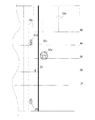
図3は撮像部120が撮像する範囲を示す図である。図3に示すように、レンズ121は一定の撮像角度すなわち画角αで車両20の前方被写界を撮像する。撮像角度α内の物体や人体は、レンズ121を介してCCDセンサ122に結像される。この場合、撮像部120のフォーカシング距離に位置し光軸125に実質的に垂直な仮想平面に含まれる物体のみがCCDセンサ122に鮮明な像を形成することができる。よって、駆動モータ123がレンズ121の各レンズを光軸125上で前方または後方に移動させて撮像部120のフォーカシング距離を変更し続けることにより、レンズ121の撮像範囲α内にある様々な物体または人体は、遠くから近くまで、あるいは近くから遠くまで、順次、CCDセンサ122に鮮明に結像される。
FIG. 3 is a diagram illustrating a range in which the
本願において、撮像部120のフォーカシング距離を増加または減少し続け、前方の異なる位置にある各物体が順次CCDセンサ122に鮮明な像を形成する動作を、「フォーカススイープ」と呼ぶ。
In the present application, an operation in which the focusing distance of the
駆動モータ123は、光学レンズに用いられる電動モータまたはピエゾ素子等のいずれの駆動手段であってもよい。制御部100は、例えば予め設定された何種類かのフォーカシング距離に従って駆動モータ123を所定の回転角度まで回転させ、そのフォーカシング距離に対応する実距離にある物体または人体をCCDセンサ122で鮮明に結像させることができる。
The
駆動モータ123がレンズ121を駆動してフォーカシングスイープを行うと、CCDセンサ122によって時系列上で複数枚の画像フレームが撮像される。例えば、図3に示すように、1回のフォーカシングスイープ動作において、フォーカシング距離が50メートル(m)、40m、30m、20m、10mというように順次シフトして、合計5枚の画像FRAME1〜FRAME5が撮像される。
When the driving
図4A〜図4Eは1回のフォーカシングスイープに撮像された複数枚の画像FRAME1〜FRAME5を示す。図4Aは、フォーカシング距離が50mである場合に撮像された画像FRAME1を示し、図4Bは、フォーカシング距離が40mである場合に撮像された画像FRAME2を示し、図4Cは、フォーカシング距離が30mである場合に撮像された画像FRAME3を示し、図4Dは、フォーカシング距離が20mである場合に撮像された画像FRAME4を示し、図4Eは、フォーカシング距離が10mである場合に撮像された画像FRAME5を示す。 4A to 4E show a plurality of images FRAME1 to FRAME5 taken in one focusing sweep. FIG. 4A shows an image FRAME1 captured when the focusing distance is 50 m, FIG. 4B shows an image FRAME2 captured when the focusing distance is 40 m, and FIG. 4C shows a focusing distance of 30 m. FIG. 4D shows an image FRAME4 picked up when the focusing distance is 20 m, and FIG. 4E shows an image FRAME5 picked up when the focusing distance is 10 m.
図4A〜図4Eにおいて、太線はCCDセンサ122上に鮮明な像が結像された物体の像を示し、細線はCCDセンサ122に鮮明な像が結像されていない物体の像を示す。
4A to 4E, a thick line indicates an image of an object on which a clear image is formed on the
図4Aに示すように、車両20前方、撮像角度α範囲内にあって車両20から50m離れた鉛直平面における物体が鮮明に結像される。ここで、CCDセンサ122に鮮明に結像された物体には、前方50mの位置にある路面標識30a、路肩30bの一部、および道路寄りの建物30cなどがある。よって、これらの物体の鮮明な像(太線)と他の物体の暈けた像、すなわち非合焦像(細線)を含む画像FRAME1が得られる。
As shown in FIG. 4A, an object on a vertical plane that is in front of the
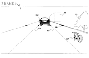
図4Bに示すように、駆動モータ123がレンズ121を駆動してフォーカシング距離が短くなると、車両20前方から40m離れた位置における物体が鮮明に結像される。ここで、CCDセンサ122で鮮明に結像された物体として前方40mの位置にある路面標識30aの一部、路肩30bの一部、および他の車両30dなどがある。そこで、これらの物体の鮮明な像と他の物体の暈けた像を含む画像FRAME2が得られる。
As shown in FIG. 4B, when the driving
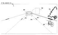
図4Cに示すように、駆動モータ123がレンズ121をさらに駆動してフォーカシング距離がさらに短くなると、車両20前方から30m離れた位置における物体が鮮明に結像される。ここで、CCDセンサ122に鮮明に結像された物体として前方30mの位置にある路面標識30aの一部、路肩30bの一部、および道路の傍の木30eなどがある。これらの物体の鮮明な像と他の物体の暈けた像を含む画像FRAME3が得られる。
As shown in FIG. 4C, when the driving
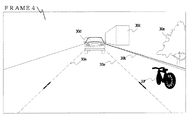
図4Dに示すように、駆動モータ123によりレンズ121をさらに駆動してフォーカシング距離がさらに短くなると、車両20前方から20m離れた位置における物体が鮮明に結像される。ここで、CCDセンサ122で鮮明に結像された物体には、前方20mの位置にある路面標識30aの一部、路肩30bの一部、および自転車30fなどがある。これらの物体の鮮明な像と他の物体の暈けた像を含む画像FRAME4が得られる。
As shown in FIG. 4D, when the
さらに、図4Eに示すように、駆動モータ123によりレンズ121を駆動してフォーカシング距離がさらに短くなると、車両20前方から10m離れた位置における物体が鮮明に結像される。ここで、CCDセンサ122で鮮明に結像した物体としては、前方10mの位置にある路面標識30aの一部、および路肩30bの一部などがある。これらの物体の鮮明な像と他の物体の暈けた像を含む画像FRAME5が得られる。
Further, as shown in FIG. 4E, when the
撮像部120により撮像された各画像FRAME1〜FRAME5は、画像信号として画像処理部140に入力され、画像処理部140において後述のように処理される。
The images FRAME1 to FRAME5 picked up by the
次に、衝突防止装置10の動作について詳細に説明する。本実施形態のフォーカシングスイープでは、最も長いフォーカシング距離を50mとし、最も短いフォーカシング距離を10mとし、1回のフォーカシングスイープにおいて、フォーカシング距離を50m、40m、30m、20m、10mと順次短くし、あるいは、10m、20m、30m、40m、50mと順次長くし、こうしてそれぞれのフォーカシング距離で画像フレームを撮り、1回のフォーカシングスイープにおいて5枚の画像FRAME1〜FRAME5が撮像される。
Next, the operation of the
図5は衝突防止装置10における処理を示すフロチャートである。同図に示すように、先ず、ステップS501においてフォーカススイープが開始する。撮像部120の駆動モータ123は、前方50mの物体がCCDセンサ122に鮮明に結像されるよう、すなわちフォーカシング距離を50mにするように、レンズ121を駆動する。
FIG. 5 is a flowchart showing processing in the
ステップS502において、CCDセンサ122は、被写界の画像FRAME1を取得し、画像FRAME1を画像処理部140へ出力する。
In step S502, the
そして、ステップS503において、画像処理部140は、撮像部120から送られた画像FRAME1において鮮明な像が結像された物体の像の有無を判別する。この例では、画像処理部140は、鮮明な像が結像された前方50m離れた路面標識30aの一部、路肩30bの一部、および道路脇の建物30cなどの物体の像を認識する。また、画像FRAME1には、車両20前方の他の車両30d、木30eおよび自転車30fなども撮像されているものの、鮮明に撮られていないため、画像処理部140により認識されることはない。
In step S503, the
また、ステップS504において、画像処理部140は、画像FRAME1の撮像時のフォーカシング距離に基づいて、これら認識した路面標識30aの部分、路肩30bの部分および建物30cなどの物体の位置を計算し、それらの物体の位置を示す分布画像を生成する。
In step S504, the
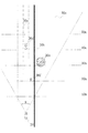
図6は画像処理部140が生成した物体分布画像を示す。この時点でのフォーカシング距離は50mであるので、前方50m離れた垂直平面内にある物体しか鮮明に結像できない。また、これら鮮明に結像された物体の画像FRAME1における座標位置は、画像FRAME1が撮られたときの角度位置により特定される。これにより、画像処理部140は、図6に示される物体分布画像において、車両20の前方、50m離れる位置に、上述の認識された路面標識30aの部分、路肩30bの部分および建物30cなどの物体を表わす図形を生成する。この図形は、一見してその物体の特性、つまりその物体が何であるかを把握できるものでよい。
FIG. 6 shows an object distribution image generated by the
そこで、ステップS505において、1回のフォーカシングスイープで撮像部120に撮像されるすべての画像フレームについて上述の処理が完了したか否かを判断し、まだ完了していない場合はステップS506へ進む。
Therefore, in step S505, it is determined whether or not the above-described processing has been completed for all image frames captured by the
ステップS506において、駆動モータ120はレンズ121を駆動してフォーカシング距離を調整する。例えば、フォーカシング距離を短くし、車両20の前方40m離れる位置にある物体をCCDセンサ122に鮮明に結像させる。
In step S506, the
次に、ステップS502以降の各ステップを再度実行する。ステップS502において、撮像部120はCCDセンサ122により画像FRAME2(図4B)を取得し、画像FRAME2を画像処理部140へ送る。
Next, each step after step S502 is executed again. In step S502, the
ステップS503において、画像処理部140は、上述した画像FRAME1についての処理と同様に、画像FRAME2から、鮮明に結像された物体として車両20の前方40m離れた路面標識30aの一部、路肩30bの一部、および他の車両30dなどを認識する。
In step S503, the
ステップS504では、前述と同様に、画像処理部140は、画像FRAME2が撮像されるときのフォーカシング距離(この場合、40m)に基づいて、物体分布画像において本車両20から40m離れた距離に相当する位置に、画像FRAME2から判別した路面標識30aの部分、路肩30bの部分、および他の車両30dなどの物体を表わす図形を生成する。
In step S504, as described above, the
そして、ステップS505では、1回のフォーカシングスイープで撮像部120に撮像される全画像フレームについて上述の処理が完了したか否かを判断し、この説明例では、引き続きFRAME3〜FRAME5を撮像すべく、同様な処理を行う。次に画像FRAME3〜FRAME5についての処理を簡単に説明する。
In step S505, it is determined whether or not the above-described processing has been completed for all image frames captured by the
撮像部120はフォーカシング距離を30mにし、画像FRAME3を撮像する。画像処理部140は、車両20の前方30m離れ、鮮明に結像された路面標識30aの一部、路肩30bの一部、および木30eなどの物体の像を認識する。画像処理部140は、図6に示す物体分布画像において、前方30mに対応する位置にこれらの物体を表わす図形を生成する。
The
次に、撮像部120はフォーカシング距離を20mにし、画像FRAME4を撮像する。画像処理部140は、車両20の前方20m離れ、鮮明に結像された路面標識30aの部分、路肩30bの部分、および自転車30fなどの物体の像を認識し、図6に示す物体分布画像において、前方20mに対応する位置にこれらの物体を表わす図形を生成する。
Next, the
さらに撮像部120は、フォーカシング距離を10mにし、画像FRAME5を撮像する。画像処理部140は、車両20の前方10m離れ、鮮明に結像された路面標識30aの一部、路肩30bの一部などの物体の像を認識し、図6に示す物体分布画像において、前方10mに対応する位置にこれらの物体を表わす図形を生成する。
Further, the
画像処理部140は、1回のフォーカシングスイープにおいて撮像される全画像フレームについて、ステップS503とS504の処理を行うと、車両20前方の物体の位置分布を示す、図6に示される物体分布画像が完成する。図6の物体分布画像には、撮像部120により撮像された車両20前方50m〜10mの範囲におけるすべての物体が含まれている。
When the
ステップS505において、1回のフォーカシングスイープに撮像される全画像フレームについて画像処理が完了したと判定されると、制御はステップS501に戻る。撮像部120は、前回使ったフォーカシング距離(この例では、10m)から再度フォーカシングスイープを行ってもよい。このとき、再度複数枚の画像フレームが撮像され、画像処理部140は次の物体分布画像を生成し、現在表示されている物体分布画像を更新する。
If it is determined in step S505 that the image processing has been completed for all image frames captured in one focusing sweep, the control returns to step S501. The
表示部200は生成された物体分布画像を表示する。車両20の運転者は、この表示から車両20の前方における建物、木、車両、自転車および歩行者を発見でき、衝突事故を効果的に回避することができる。また、物体分布画像により、車両20の運転者に道路標識および路肩などの標識物を知らせることができ、運転者は表示された路面標識に沿って車両20を容易に操縦することができる。
The
また、衝突判断部310は、画像処理部140で生成される物体分布画像に基づき、車両20が障害物などに衝突するか否かを判断することができる。
The collision determination unit 310 can determine whether the
車両20から前方にある障害物との距離が所定の安全距離より短い場合、衝突判断部310は衝突する危険があると判断し、表示部200は、目立つ色、例えば赤色でその危険性障害物を表示して車両20の運転者に知らせる。また、音声部210が警告音を発生して警告してもよい。さらに、振動部220が振動して警告してもよい。
When the distance from the
また、画像処理部140が生成した物体分布画像には、建物、樹木、植込みなどの路傍構造物、他の自動車や、自転車などの軽車両、歩行者のほか、路面標識や路肩も表示されている。よって、衝突判断部310は、自車両20がそのような路面標識や路肩と「衝突」するか否かを判断することがある。衝突判断部310は、車両20が路面標識や路肩と衝突すると判断すると、車両20が現在の車線から逸れていることを表示する。この場合、表示部200、音声部210および/または振動部220は、車両20の運転者に車両20の進行方向を変更するように警告する。これにより、例えば高速道路で運転者が疲れて車線から逸脱し、事故を起こす危険性を回避でき、車両20の安全性を向上させることができる。
In addition, the object distribution image generated by the
衝突防止装置10にはさらに、車両20の速度を検出する速度検出部150が設けられている。衝突判断部310は、速度検出部150が検出した車両20の速度に基づき、安全距離をリアルタイムに計算でき、より有効に衝突を防止できる。
The
衝突防止装置10において、車両20の走行速度に対応する安全距離の情報を、例えばROM 230などの記録媒体に予め保存してもよい。衝突判断部310は、速度検出部150の検出した車両20の速度から数式を用いて安全距離をリアルタイムに計算してもよい。
In the
また、衝突防止装置10において、衝突判断部310が衝突し得ると判断すると、制御部100の制御の下に車両制御部400が車両20の操縦駆動系を制御して、車両20の制動、加速および/または操舵、つまりブレーキ、アクセルおよびハンドリングなどを行う。こうして、衝突判断部310が画像処理部140で生成された物体分布画像から車両20の前方障害物との衝突の可能性を判断した場合、車両制御部400により車両20と前方車両と間に所定の安全距離を保つように、車両20を制動することができる。
Further, in the
一方、車両20が車線からずれると、車両制御部400により車両20の操舵を行い、車両20の車線からの逸脱を防止できる。勿論、車両20の運転者が意図的に車線を変更する場合もある。そのときは、運転者が少し強く車両制御部400による動作に抵抗するように操作すると、装置の操作検出部(図示せず)がこの操作を検出し、これによって車両制御部400の制御は即座に解除され、運転者による車両20の制御を許容することになる。
On the other hand, when the
さらに、車両20の撮像部120は高速撮像を行うことが望ましい。撮像部120を高速に撮像するように構成すれば、各画像フレームの露光時間が短くなるので、車両20の高速走行時の振動による各画像フレームのボケを抑制し、したがって画像処理部140は、撮像された画像から物体を確実に認識できる。また、撮像部120で高速撮像を行うことにより、車両20の走行方向において長い距離の範囲内で精密に物体を認識でき、また物体分布画像の更新速度も速くなる。これにより、表示部200に表示される物体分布画像の実時間性がさらに向上する。
Furthermore, it is desirable that the
上述の実施形態は、撮像部120が1回のフォーカシングスイープに5枚の画像フレームを撮像し、最長フォーカシング距離は50mであり、最短フォーカシング距離は10mであり、その間の各フォーカシング距離のステップ幅は10mであった。これは一例にすぎず、例えば、車両20前方にあるすべての物体の認識を可能とするように、連続撮像した2枚の画像フレーム間のフォーカシング距離のステップ幅を短くすれば、物体分布画像における各物体の認識精度がそれだけ高くなり、したがって小さな物体や、走行方向にほぼ垂直な方向において隣接する物体や人体も認識して表示することができる。これにより、画像処理部140において各画像フレームを処理する負荷は増加する。しかし、このような物体を認識する認識精度を選択可能に設定し、使用者は、状況に応じて、必要な精度を保ちながら画像処理部140の負荷を低減するような、最適なフォーカシング距離のステップ幅を決めるように構成してもよい。連続して撮像される2枚の画像フレームのフォーカシング距離のステップ幅は、2m以下であることが好ましく、1m以下であることがより好ましい。
In the above-described embodiment, the
一方、最も長いフォーカシング距離と最も短いフォーカシング距離は、それぞれ、上述した50mと10m以外の値に設定してもよい。車両20の安全性を向上させるため、最も長いフォーカシング距離を50m以上に、最も短いフォーカシング距離を5m以下にすることが望ましい。さらに、速度検出部150の検出した車両20の走行速度に応じて最長フォーカシング距離が増大するように構成してもよい。その場合、最短フォーカシング距離も対応して増大させてもよい。こうして、市街地走行や高速道路走行に適応的に対応することができる。
On the other hand, the longest focusing distance and the shortest focusing distance may be set to values other than the above-described 50 m and 10 m, respectively. In order to improve the safety of the
また、本実施形態では、撮像部120はフォーカシングスイープを行う度に、画像処理部140は物体分布画像を生成し、これを更新する。衝突防止装置10は実時間性が重要な要素のひとつであるが、これを向上させるために、撮像部120は1秒間に1回以上フォーカシングスイープを行って物体分布画像を更新することが望ましい。さらに、車両20が高速に走行するとき、衝突防止装置10の実時間性を一般道走行時より向上させることが望ましいが、撮像部120は1秒に5回以上のフォーカシングスウィープを行って物体分布画像を更新することが望ましい。そのために、撮像部120は500回/秒の速度で高速撮像することが望ましい。例えば、車両20前方100m〜1mの広い距離範囲内にある物体を認識することができ、また、5回/秒以上の頻度で物体分布画像を更新することができる。このように、物体認識の範囲、精度および実時間性が向上する。
In the present embodiment, every time the
上述の実施形態では、撮像部120は車両20の前部に1台設けられていた。しかし、本発明はこれに限定されない。例えば、車両20の後部にも同様の撮像部を設けてもよく、これにより、車両20の運転者は車両後方の物体分布および車両状況を把握することができる。車両進行中、後方から他の車両が所定の安全距離以下に接近すると、表示部200、音声部210または振動部220により自車両20の運転者にこれを知らせ、運転者に対応するように促すことができる。これによってさらに安全に、後方からの車両の追尾事故を回避することが可能となる。また、車両制御部400は、後方からの車両に至近距離で追尾されないように、車両20を加速するように構成してもよい。
In the embodiment described above, one
さらに、車両20の側部および/または後部の複数の箇所に、複数の撮像部を設けてもよい。これにより、車両20の横方向および/または後方の物体を認識または検出し、車両を道路の側方、駐車場または車庫に駐車する時、運転者は、車両20の周囲にある路肩や壁などの障害物、および駐車標識の位置を把握でき、駐車の際の衝突事故を回避することができる。また、車両制御部400で車両20を前向きまたは後向き移動、操舵、および加速もしくはブレーキ制御をすることにより、運転者の操作なくして、または最少の操作で、駐車できるように構成してもよい。
Furthermore, a plurality of imaging units may be provided at a plurality of locations on the side and / or rear of the
車両20に複数の撮像部を配置し、各撮像部が異なる方向に向いて撮像することにより、画像処理部140により、車両20周囲のより広い範囲における物体や人体の分布を示す画像を生成することができ、使用上の便利性が向上する。
By arranging a plurality of imaging units on the
また、画像処理部140は、生成される物体分布画像において本車両20との距離を示す格子線を付加的に可視表示するように構成してもよい。これにより、車両20の運転者は、表示部200に表示される物体分布画像より、自車両から認識された物体までの距離を知ることができ、車進行中の安全性をさらに確保できる。
The
上述の実施形態は、撮像部120がCCDセンサ122を備えていた。しかし、本発明はこのような撮像デバイスの特定の種類に限れない。撮像素子として、相補型金属酸化膜半導体(CMOS)センサまたは他の光学センサを利用してもよい。また、表示部200は、物体の色を表示しない場合、単色の撮像素子を使用してもよい。これは衝突防止装置120のコストの低減に寄与し、画像処理部140における処理速度を向上できる。
In the above-described embodiment, the
また、夜間やトンネル内などの暗い環境での利用に対応するため、撮像素子として赤外線センサを用いてもよい。これにより、例えば、夜でも撮像部120が車両20の周囲の照明の届かない領域にある物体や人体を撮像でき、画像処理部140が画像フレームから物体や人体を判別することができ、衝突防止装置10の実用性がさらに向上する。
Further, an infrared sensor may be used as the imaging element in order to cope with use in a dark environment such as at night or in a tunnel. Thereby, for example, the
上述の実施形態は、画像処理部140が図6に示すような平面物体分布画像を生成するものであった。しかし、本発明はこれに限れない。画像処理部140が3次元(立体)物体分布画像を生成するように構成してもよい。
In the above-described embodiment, the
図7は、画像処理部140が3次元の物体分布画像を生成する方法を説明する模式図である。同図には、図4A〜図4Eに示した画像FRAME1からFRAME5がそれぞれのフォーカシング距離に応じた位置に配置され、撮像部120の撮像角度αに応じたフレームサイズで立体的に見えるよう表示された状態が示されている。
FIG. 7 is a schematic diagram illustrating a method by which the
図5に示されるステップS503と同じように、画像処理部140は、画像FRAME1からFRAME5において、鮮明な像が結像された物体を認識する。
As in step S503 shown in FIG. 5, the
また、図5に示されるステップS504のように、画像処理部140は、画像FRAME1からFRAME5の撮像時のフォーカシング距離に基づいて、これらの認識された物体の位置を計算し、それらの物体の位置分布を可視的に表わす立体画像を生成する。具体的には、認識された物体の画像FRAME1からFRAME5のそれぞれにおける位置は、画像FRAME1からFRAME5が撮られた時のそれぞれの角度位置により求まる。そこで画像処理部140は、立体空間において、車両20の前方におけるそれぞれのフォーカシング距離の位置に、これらの認識された物体の図形を表示する立体図形127を生成する。こうして、3次元(立体)物体分布画像127が生成される。
Further, as in step S504 shown in FIG. 5, the
表示部200は、3次元の物体分布画像を表示するとき、車両20の運転者の操作により物体分布画像127を表示する視角を変更することができる。例えば、鳥瞰図の視角で表示するように視角を変換することができる。これにより、車両20の運転者は直接または直感的に、車両20前方の各物体の正確な位置を把握することができる。また、立体物体分布画像127を表示する視角を運転者が極限値に設定すれば、図6を参照して前述した実施形態と同様に、平面の物体分布画像を表示することもできる。
When displaying the three-dimensional object distribution image, the
上述の実施形態は、撮像部120の撮像角度αが固定、すなわちレンズ121が単焦点レンズであった。しかし、撮像角度αは可変、すなわちレンズ121はズームレンズであってもよい。ズームレンズはズーミング機構によって駆動され、ズーミング機構は、フォーカススイープにおいて、例えば、フォーカシング距離を短くするときは焦点距離を短くして撮像角度αを大きくし、これにより近くに位置する物体をできるだけ多く認識することができる。一方、フォーカシング距離を長くする場合は、焦点距離を長くして撮影角度を小さくし、これにより遠くにある物体は画像フレームにおいてサイズが大きく描写される。こうして、物体や人体の認識率がさらに向上する。
In the above-described embodiment, the imaging angle α of the
また、上述の実施形態では、車両20は移動体の一例であったが、本発明に係る移動体衝突防止装置は、陸上のみならず、移動可能な、とくに自律走行可能な装置または生産や採掘現場、構内で使用される運搬機構に配置してもよい。
Further, in the above-described embodiment, the
以上、本発明の最良の実施形態を説明したが、本発明はこれに限るものではない。衝突防止装置10における一部の構成要素により各部分の機能および効果を得ることも可能である。
The best embodiment of the present invention has been described above, but the present invention is not limited to this. It is also possible to obtain the functions and effects of each part with some components in the
本発明を具体的な実施形態に則して詳細に説明したが、形式や細部についての種々の置換、変形、変更などが特許請求の範囲の記載により規定されるような本発明の精神および範囲から逸脱することなく行われることが可能であることは、当業者に明らかである。例えば、衝突防止装置10における一部の構成を利用し、各構成の各々の効果を得ることができる。したがって、本発明の範囲は、前述の実施形態および添付図面の記載に限定されるものでなく、特許請求の範囲の記載およびこれと均等なものに基づいて定められるべきである。
Although the present invention has been described in detail with reference to specific embodiments, the spirit and scope of the present invention such that various substitutions, modifications, and changes in form and detail are defined by the appended claims. It will be apparent to those skilled in the art that this can be done without departing from the above. For example, a part of the configuration of the
本発明による画像処理装置は、生産現場における各設備の位置識別および監視制御、スポーツ試合の生中継における視角の切替え、およびインタラクティブな娯楽システムや移動体衝突防止装置に適用することができる。 The image processing apparatus according to the present invention can be applied to position identification and monitoring control of each facility at a production site, switching of a viewing angle in a live broadcast of a sports game, and an interactive entertainment system and a mobile object collision prevention apparatus.
α 撮像部の撮像角度
10 移動体衝突防止装置
20 車両である移動体
100 制御部
120 撮像部
121 レンズ
122 CCDセンサ
123 合焦機構
140 画像処理部
150 速度検出部
200 表示部
210 音声部
220 振動部
230 ROM
310 衝突判断部
30a 路面標識
30b 路肩
30c 建物
30d 自動車
30e 木
30f 自転車
400 車両制御部
α Imaging angle of the imaging unit
10 Moving object collision prevention device
20 Vehicles that are vehicles
100 Control unit
120 Imaging unit
121 lens
122 CCD sensor
123 Focusing mechanism
140 Image processor
150 Speed detector
200 display
210 Voice
220 Vibration part
230 ROM
310 Collision determination unit
30a road marking
30b shoulder
30c building
30d car
30e wood
30f bicycle
400 Vehicle control unit
Claims (14)
前記撮像手段が撮像した画像を処理する画像処理手段とを備え、
前記撮像手段は、撮像レンズと、該撮像レンズを駆動してフォーカシング距離を変更する合焦機構と、撮像素子とを有し、
該合焦機構は、前記撮像レンズを駆動して、該撮像レンズの光軸方向における異なる位置の物体を前記撮像素子に鮮明に結像させるように順次フォーカシング距離を変更するフォーカススイープを行い、
前記撮像手段は、前記フォーカススイープにおいて複数の異なるフォーカシング距離に応じてそれぞれ画像を撮像し、
前記画像処理手段は、前記撮像された複数枚の画像から、該複数枚の画像のそれぞれにおいて鮮明に結像された物体を認識し、該複数枚の画像のそれぞれの撮像時のフォーカシング距離に対応して前記認識された物体の位置を表示する物体分布画像を生成することを特徴とする画像処理装置。 Imaging means;
Image processing means for processing an image picked up by the image pickup means,
The imaging means includes an imaging lens, a focusing mechanism that drives the imaging lens to change a focusing distance, and an imaging element,
The focusing mechanism drives the imaging lens to perform a focus sweep that sequentially changes a focusing distance so that an object at a different position in the optical axis direction of the imaging lens is clearly imaged on the imaging element;
The imaging means captures images according to a plurality of different focusing distances in the focus sweep,
The image processing unit recognizes an object that is clearly formed in each of the plurality of images from the plurality of captured images, and corresponds to a focusing distance at the time of capturing each of the plurality of images. And generating an object distribution image for displaying the position of the recognized object.
前記撮像手段は前記フォーカススイープを繰り返して複数回行い、
前記画像処理手段は、該複数回のフォーカススイープに対応して前記物体分布画像を複数枚生成することを特徴とする画像処理装置。 The device according to any one of claims 1 to 3,
The imaging means repeats the focus sweep a plurality of times,
The image processing device generates the plurality of object distribution images corresponding to the plurality of focus sweeps.
前記撮像手段は、該ズームレンズを駆動しその焦点距離を変更するズーミング機構を備え、
該ズーミング機構は、前記フォーカシング距離が所定値より長くなるとき、ズームレンズを駆動してその焦点距離を長くし、前記フォーカシング距離が所定値より短くなるとき、前記ズームレンズを駆動してその焦点距離を短くすることを特徴とする画像処理装置。 The apparatus according to claim 1, wherein the imaging lens includes a zoom lens;
The imaging means includes a zooming mechanism that drives the zoom lens and changes its focal length.
When the focusing distance becomes longer than a predetermined value, the zooming mechanism drives the zoom lens to increase the focal length, and when the focusing distance becomes shorter than the predetermined value, the zooming mechanism drives the zoom lens to increase the focal length. An image processing apparatus characterized by shortening the length.
前記撮像手段において、前記合焦機構は、前記撮像レンズを駆動して該撮像レンズの光軸方向における異なる位置の物体を前記撮像素子に鮮明に結像させるように順次フォーカシング距離を変更するフォーカススイープを行い、該フォーカススイープにおいて複数の異なるフォーカシング距離に応じてそれぞれの画像を撮像し、
前記画像処理手段において、前記撮像された複数枚の画像から、該複数枚の画像のそれぞれにおいて鮮明に結像された物体を認識し、該複数枚の画像のそれぞれの撮像時のフォーカシング距離に対応して前記認識された物体の位置を表示する物体分布画像を生成することを特徴とする画像処理方法。 Image processing method in an image processing apparatus comprising: an imaging lens; a focusing mechanism that drives the imaging lens to change a focusing distance; an imaging unit having an imaging element; and an image processing unit that processes an image captured by the imaging unit Because
In the imaging unit, the focusing mechanism sequentially changes a focusing distance so as to drive the imaging lens to clearly form an object at a different position in the optical axis direction of the imaging lens on the imaging element. And taking each image according to a plurality of different focusing distances in the focus sweep,
The image processing means recognizes an object that is clearly formed in each of the plurality of images from the plurality of captured images, and corresponds to a focusing distance at the time of capturing each of the plurality of images. And generating an object distribution image for displaying the position of the recognized object.
該移動体の周囲を撮像する撮像手段と、
該撮像手段が撮像した画像を処理する画像処理手段と、
衝突判定手段とを備え、
前記撮像手段は、撮像レンズと、該撮像レンズを駆動してフォーカシング距離を変更する合焦機構と、撮像素子とを有し、
該合焦機構は、前記撮像レンズを駆動して、前記移動体から離れている複数の物体を前記撮像素子に鮮明に結像させるように順次フォーカシング距離を変更するフォーカススイープを行い、
前記撮像手段は、該フォーカススイープにおいて複数の異なるフォーカシング距離に応じてそれぞれ画像を撮像し、
前記画像処理手段は、前記撮像された複数枚の画像から、該複数枚の画像のそれぞれにおいて鮮明に結像された物体を認識し、該複数枚の画像のそれぞれの撮像時のフォーカシング距離に対応して前記認識された物体の位置を表示する物体分布画像を生成し、
前記衝突判定手段は、該物体分布画像に基づいて前記移動体と前記認識された物体とが衝突するか否かを判定することを特徴とする移動体衝突防止装置。 A moving body collision prevention device provided on a moving body,
Imaging means for imaging the periphery of the moving body;
Image processing means for processing an image picked up by the image pickup means;
A collision determination means,
The imaging means includes an imaging lens, a focusing mechanism that drives the imaging lens to change a focusing distance, and an imaging element,
The focusing mechanism drives the imaging lens to perform a focus sweep that sequentially changes a focusing distance so that a plurality of objects separated from the moving body are clearly imaged on the imaging element;
The imaging means captures images according to a plurality of different focusing distances in the focus sweep,
The image processing unit recognizes an object that is clearly formed in each of the plurality of images from the plurality of captured images, and corresponds to a focusing distance at the time of capturing each of the plurality of images. And generating an object distribution image displaying the position of the recognized object,
The collision detection apparatus according to claim 1, wherein the collision determination unit determines whether or not the mobile object and the recognized object collide based on the object distribution image.
前記衝突判定手段は、前記移動体と前記認識された物体とが衝突すると判定すると、前記表示手段は、該物体を異なる色で表示することを特徴とする移動体衝突防止装置。 The apparatus according to claim 10, further comprising display means for displaying the object distribution image.
When the collision determination unit determines that the moving body and the recognized object collide, the display unit displays the object in a different color.
前記移動体と前記認識された物体とが衝突すると前記衝突判定手段が判定すると、前記通知手段は前記操縦者へ警告メッセージを発生することを特徴とする移動体衝突防止装置。 The apparatus according to claim 10, further comprising notification means for notifying a pilot of the mobile body.
The mobile body collision prevention apparatus according to claim 1, wherein when the collision determination unit determines that the mobile body and the recognized object collide, the notification unit generates a warning message to the operator.
該移動体の周囲を撮像する撮像手段と、
該撮像手段が撮像した画像を処理する画像処理手段と、
表示手段とを備え、
前記撮像手段は、撮像レンズと、該撮像レンズを駆動しフォーカシング距離を変更する合焦機構と、撮像素子とを有し、
該合焦機構は、前記撮像レンズを駆動して、前記移動体から離れている複数の物体を前記撮像素子に鮮明に結像させるように順次フォーカシング距離を変更するフォーカススイープを行い、
前記撮像手段は、該フォーカススイープにおいて複数の異なるフォーカシング距離に応じてそれぞれの画像を撮像し、
前記画像処理手段は、前記撮像された複数枚の画像から、該複数枚の画像のそれぞれにおいて鮮明に結像された物体を認識し、該複数枚の画像のそれぞれの撮像時のフォーカシング距離に対応して前記認識された物体の位置を表示する物体分布画像を生成し、
前記表示手段は、該記物体分布画像を表示することを特徴とする移動体衝突防止装置。 A moving body collision prevention device provided on a moving body,
Imaging means for imaging the periphery of the moving body;
Image processing means for processing an image picked up by the image pickup means;
Display means,
The imaging means includes an imaging lens, a focusing mechanism that drives the imaging lens to change a focusing distance, and an imaging device,
The focusing mechanism drives the imaging lens to perform a focus sweep that sequentially changes a focusing distance so that a plurality of objects separated from the moving body are clearly imaged on the imaging element;
The imaging means captures each image according to a plurality of different focusing distances in the focus sweep,
The image processing unit recognizes an object that is clearly formed in each of the plurality of images from the plurality of captured images, and corresponds to a focusing distance at the time of capturing each of the plurality of images. And generating an object distribution image displaying the position of the recognized object,
The moving object collision preventing apparatus, wherein the display means displays the recorded object distribution image.
14. The mobile object collision preventing apparatus according to claim 13, wherein the display unit displays the object distribution image as a three-dimensional image.
Applications Claiming Priority (2)
| Application Number | Priority Date | Filing Date | Title |
|---|---|---|---|
| CN201110065887.9A CN102685382B (en) | 2011-03-18 | 2011-03-18 | Image processing apparatus and method and moving body collision prevention device |
| CN201110065887.9 | 2011-03-18 |
Publications (2)
| Publication Number | Publication Date |
|---|---|
| JP2012198207A true JP2012198207A (en) | 2012-10-18 |
| JP5536125B2 JP5536125B2 (en) | 2014-07-02 |
Family
ID=45977084
Family Applications (1)
| Application Number | Title | Priority Date | Filing Date |
|---|---|---|---|
| JP2012060124A Active JP5536125B2 (en) | 2011-03-18 | 2012-03-16 | Image processing apparatus and method, and moving object collision prevention apparatus |
Country Status (5)
| Country | Link |
|---|---|
| US (1) | US9858488B2 (en) |
| EP (1) | EP2500890B1 (en) |
| JP (1) | JP5536125B2 (en) |
| CN (1) | CN102685382B (en) |
| ES (1) | ES2886522T3 (en) |
Cited By (3)
| Publication number | Priority date | Publication date | Assignee | Title |
|---|---|---|---|---|
| JP2015031978A (en) * | 2013-07-31 | 2015-02-16 | 日産自動車株式会社 | Information providing device and method |
| CN105185160A (en) * | 2015-10-09 | 2015-12-23 | 卢庆港 | Pavement detection system and detection method |
| JP2017215525A (en) * | 2016-06-01 | 2017-12-07 | キヤノン株式会社 | Imaging device and method for controlling the same, program, and storage medium |
Families Citing this family (31)
| Publication number | Priority date | Publication date | Assignee | Title |
|---|---|---|---|---|
| CN102923082A (en) * | 2012-10-31 | 2013-02-13 | 东莞康特尔电子有限公司 | Vehicle driving intelligent protection early warning system and control method thereof |
| CN103101497A (en) * | 2013-01-25 | 2013-05-15 | 深圳市保千里电子有限公司 | Automobile picture pick-up system and data process method of synchronous change of visual angle of automobile picture pick-up system and automobile speed |
| CN103072537B (en) * | 2013-02-05 | 2014-03-26 | 湖南大学 | Automotive collision avoidance safety protecting method based on infrared image processing |
| JP2014191688A (en) * | 2013-03-28 | 2014-10-06 | Sony Corp | Information processor, information processing method and storage medium |
| CN104349197B (en) * | 2013-08-09 | 2019-07-26 | 联想(北京)有限公司 | A kind of data processing method and device |
| DE102013222304A1 (en) * | 2013-11-04 | 2015-05-07 | Conti Temic Microelectronic Gmbh | Method for determining object distances with a camera installed in a motor vehicle |
| KR20150110283A (en) * | 2014-03-21 | 2015-10-02 | 삼성전자주식회사 | Method and apparatus for preventing a collision between objects |
| US10130873B2 (en) | 2014-03-21 | 2018-11-20 | Samsung Electronics Co., Ltd. | Method and apparatus for preventing a collision between subjects |
| CN105025219A (en) * | 2014-04-30 | 2015-11-04 | 齐发光电股份有限公司 | Image acquisition method |
| CN105270258A (en) * | 2014-06-12 | 2016-01-27 | 陕西重型汽车有限公司 | Automotive steering safety assistance system |
| US9576185B1 (en) * | 2015-09-14 | 2017-02-21 | Toyota Motor Engineering & Manufacturing North America, Inc. | Classifying objects detected by 3D sensors for autonomous vehicle operation |
| US9676326B2 (en) * | 2015-09-25 | 2017-06-13 | Ford Global Technologies, Llc | Drive history parking barrier alert |
| KR101822895B1 (en) | 2016-04-07 | 2018-01-29 | 엘지전자 주식회사 | Driver assistance apparatus and Vehicle |
| CN106080481A (en) * | 2016-07-22 | 2016-11-09 | 池州学院 | A kind of automobile omnibearing anti-collision early warning system |
| US10403141B2 (en) * | 2016-08-19 | 2019-09-03 | Sony Corporation | System and method for processing traffic sound data to provide driver assistance |
| US11528413B2 (en) | 2016-08-22 | 2022-12-13 | Sony Corporation | Image processing apparatus and image processing method to generate and display an image based on a vehicle movement |
| CN106571046B (en) * | 2016-11-11 | 2021-07-16 | 上海市政工程设计研究总院(集团)有限公司 | Vehicle-road cooperative driving assisting method based on road surface grid system |
| CN106683408A (en) * | 2017-02-14 | 2017-05-17 | 北京小米移动软件有限公司 | Vehicle monitoring method and device |
| JP6582153B2 (en) * | 2017-03-15 | 2019-09-25 | 富士フイルム株式会社 | Imaging apparatus, imaging method, and imaging program |
| JP6579144B2 (en) * | 2017-03-28 | 2019-09-25 | 株式会社Soken | Obstacle detection device |
| US20190039515A1 (en) * | 2017-08-01 | 2019-02-07 | Nanning Fugui Precision Industrial Co., Ltd. | System and method for warning against vehicular collisions when driving |
| CN107672551B (en) * | 2017-09-20 | 2020-07-17 | 杭州奥腾电子股份有限公司 | Front vehicle anti-collision early warning system and control method thereof |
| US10678257B2 (en) * | 2017-09-28 | 2020-06-09 | Nec Corporation | Generating occlusion-aware bird eye view representations of complex road scenes |
| DE102018209388A1 (en) * | 2018-06-13 | 2019-12-19 | Robert Bosch Gmbh | Detection of driving-relevant situations at a greater distance |
| CN109532670B (en) * | 2018-11-28 | 2022-02-22 | 广州市网拓信息技术有限公司 | Vehicle-mounted safe distance judgment device and software use principle thereof |
| DE102018221241A1 (en) | 2018-12-07 | 2020-06-10 | Volkswagen Aktiengesellschaft | Driver assistance system for a motor vehicle, motor vehicle and method for operating a motor vehicle |
| CN112380935B (en) * | 2020-11-03 | 2023-05-26 | 深圳技术大学 | Man-machine collaborative sensing method and system for automatic driving |
| JP2022114764A (en) * | 2021-01-27 | 2022-08-08 | キヤノン株式会社 | Optical system, image capturing device, in-vehicle system, and mobile device |
| CN112995507A (en) * | 2021-02-08 | 2021-06-18 | 北京蜂巢世纪科技有限公司 | Method and device for prompting object position |
| CN114071020A (en) * | 2021-12-28 | 2022-02-18 | 厦门四信通信科技有限公司 | Automatic zooming method and device for unmanned vehicle |
| US20230322248A1 (en) * | 2022-04-06 | 2023-10-12 | Gm Global Technology Operation Llc | Collision warning system for a motor vehicle having an augmented reality head up display |
Citations (11)
| Publication number | Priority date | Publication date | Assignee | Title |
|---|---|---|---|---|
| JPH0580143A (en) * | 1991-09-19 | 1993-04-02 | Fujitsu Ltd | Rader signal display device |
| JPH10143245A (en) * | 1996-11-07 | 1998-05-29 | Komatsu Ltd | Obstacle collision preventing device for mobile object |
| JP2004094825A (en) * | 2002-09-03 | 2004-03-25 | Toyota Motor Corp | Three-dimensional object recognition device |
| JP2004348645A (en) * | 2003-05-26 | 2004-12-09 | Honda Motor Co Ltd | Infrared image recognition apparatus and alarm equipment using the same |
| JP2007172541A (en) * | 2005-12-26 | 2007-07-05 | Toyota Motor Corp | Driving support device |
| JP2007192730A (en) * | 2006-01-20 | 2007-08-02 | Nsk Ltd | Multipoint ranging sensor and multipoint ranging technique |
| JP2008028951A (en) * | 2006-07-25 | 2008-02-07 | Canon Inc | Imaging apparatus, imaging method, program, and storage medium |
| JP2008225140A (en) * | 2007-03-14 | 2008-09-25 | Fujifilm Corp | Lens moving device and digital camera |
| JP2009008655A (en) * | 2007-02-06 | 2009-01-15 | Honeywell Internatl Inc | Method and system for three-dimensional obstacle mapping for navigation of autonomous vehicle |
| JP2010066156A (en) * | 2008-09-11 | 2010-03-25 | Nikon Corp | Profile measuring apparatus |
| JP2010191793A (en) * | 2009-02-19 | 2010-09-02 | Denso It Laboratory Inc | Alarm display and alarm display method |
Family Cites Families (22)
| Publication number | Priority date | Publication date | Assignee | Title |
|---|---|---|---|---|
| JP2715202B2 (en) | 1991-10-09 | 1998-02-18 | 新キャタピラー三菱株式会社 | Wireless monitoring communication method and apparatus for unmanned self-propelled body |
| CN1099342A (en) * | 1993-08-25 | 1995-03-01 | 徐顺庆 | Method and device for protecting against collision of driving vehicles |
| JP3260645B2 (en) | 1997-01-31 | 2002-02-25 | エニー株式会社 | Navigation system |
| JPH11120499A (en) | 1997-10-09 | 1999-04-30 | Toyo Commun Equip Co Ltd | Position display device for navigation |
| JP2000304856A (en) | 1999-04-20 | 2000-11-02 | Mitsubishi Electric Engineering Co Ltd | Approach alarm device |
| JP3642717B2 (en) | 2000-05-30 | 2005-04-27 | 櫻護謨株式会社 | Travel restriction system for automatic traveling machine |
| JP2003016429A (en) * | 2001-06-28 | 2003-01-17 | Honda Motor Co Ltd | Vehicle periphery monitor device |
| US7084910B2 (en) * | 2002-02-08 | 2006-08-01 | Hewlett-Packard Development Company, L.P. | System and method for using multiple images in a digital image capture device |
| US7319487B2 (en) * | 2002-04-10 | 2008-01-15 | Olympus Optical Co., Ltd. | Focusing apparatus, camera and focus position detecting method |
| EP1901225A1 (en) * | 2005-05-10 | 2008-03-19 | Olympus Corporation | Image processing device, image processing method, and image processing program |
| JP2007004020A (en) * | 2005-06-27 | 2007-01-11 | Sony Corp | Zoom lens and imaging apparatus |
| US20070035628A1 (en) * | 2005-08-12 | 2007-02-15 | Kunihiko Kanai | Image-capturing device having multiple optical systems |
| WO2007102367A1 (en) * | 2006-02-28 | 2007-09-13 | Toyota Jidosha Kabushiki Kaisha | Object course prediction method, device, program, and automatic driving system |
| US20100134631A1 (en) * | 2006-10-30 | 2010-06-03 | Wesleyan University | Apparatus and method for real time image compression for particle tracking |
| CN100578148C (en) * | 2007-05-25 | 2010-01-06 | 财团法人车辆研究测试中心 | Detection method for vehicle side collision alarming device |
| US20100259631A1 (en) * | 2007-10-26 | 2010-10-14 | Fujifilm Corporation | Data compression apparatus, data compression program and image-taking apparatus |
| CN101458078A (en) * | 2007-12-10 | 2009-06-17 | 鸿富锦精密工业(深圳)有限公司 | Automobile anti-collision system and method |
| JP2009151124A (en) * | 2007-12-20 | 2009-07-09 | Sharp Corp | Sensor module, electronic information device, autofocus control method, control program, and readable storage medium |
| US20110019873A1 (en) * | 2008-02-04 | 2011-01-27 | Konica Minolta Holdings, Inc. | Periphery monitoring device and periphery monitoring method |
| US8050468B2 (en) * | 2008-03-05 | 2011-11-01 | Honeywell International Inc. | Fingerprint acquisition system |
| US8054201B2 (en) * | 2008-03-19 | 2011-11-08 | Mazda Motor Corporation | Surroundings monitoring device for vehicle |
| KR20110020519A (en) * | 2009-08-24 | 2011-03-03 | 삼성전자주식회사 | Digital photographing apparatus, controlling method of the same, and recording medium storing program to implement the method |
-
2011
- 2011-03-18 CN CN201110065887.9A patent/CN102685382B/en active Active
-
2012
- 2012-03-12 ES ES12001674T patent/ES2886522T3/en active Active
- 2012-03-12 EP EP12001674.6A patent/EP2500890B1/en active Active
- 2012-03-16 US US13/422,803 patent/US9858488B2/en active Active
- 2012-03-16 JP JP2012060124A patent/JP5536125B2/en active Active
Patent Citations (11)
| Publication number | Priority date | Publication date | Assignee | Title |
|---|---|---|---|---|
| JPH0580143A (en) * | 1991-09-19 | 1993-04-02 | Fujitsu Ltd | Rader signal display device |
| JPH10143245A (en) * | 1996-11-07 | 1998-05-29 | Komatsu Ltd | Obstacle collision preventing device for mobile object |
| JP2004094825A (en) * | 2002-09-03 | 2004-03-25 | Toyota Motor Corp | Three-dimensional object recognition device |
| JP2004348645A (en) * | 2003-05-26 | 2004-12-09 | Honda Motor Co Ltd | Infrared image recognition apparatus and alarm equipment using the same |
| JP2007172541A (en) * | 2005-12-26 | 2007-07-05 | Toyota Motor Corp | Driving support device |
| JP2007192730A (en) * | 2006-01-20 | 2007-08-02 | Nsk Ltd | Multipoint ranging sensor and multipoint ranging technique |
| JP2008028951A (en) * | 2006-07-25 | 2008-02-07 | Canon Inc | Imaging apparatus, imaging method, program, and storage medium |
| JP2009008655A (en) * | 2007-02-06 | 2009-01-15 | Honeywell Internatl Inc | Method and system for three-dimensional obstacle mapping for navigation of autonomous vehicle |
| JP2008225140A (en) * | 2007-03-14 | 2008-09-25 | Fujifilm Corp | Lens moving device and digital camera |
| JP2010066156A (en) * | 2008-09-11 | 2010-03-25 | Nikon Corp | Profile measuring apparatus |
| JP2010191793A (en) * | 2009-02-19 | 2010-09-02 | Denso It Laboratory Inc | Alarm display and alarm display method |
Cited By (3)
| Publication number | Priority date | Publication date | Assignee | Title |
|---|---|---|---|---|
| JP2015031978A (en) * | 2013-07-31 | 2015-02-16 | 日産自動車株式会社 | Information providing device and method |
| CN105185160A (en) * | 2015-10-09 | 2015-12-23 | 卢庆港 | Pavement detection system and detection method |
| JP2017215525A (en) * | 2016-06-01 | 2017-12-07 | キヤノン株式会社 | Imaging device and method for controlling the same, program, and storage medium |
Also Published As
| Publication number | Publication date |
|---|---|
| US9858488B2 (en) | 2018-01-02 |
| EP2500890A3 (en) | 2016-12-07 |
| ES2886522T3 (en) | 2021-12-20 |
| CN102685382B (en) | 2016-01-20 |
| CN102685382A (en) | 2012-09-19 |
| US20120236122A1 (en) | 2012-09-20 |
| EP2500890A2 (en) | 2012-09-19 |
| EP2500890B1 (en) | 2021-08-04 |
| JP5536125B2 (en) | 2014-07-02 |
Similar Documents
| Publication | Publication Date | Title |
|---|---|---|
| JP5536125B2 (en) | Image processing apparatus and method, and moving object collision prevention apparatus | |
| US10387733B2 (en) | Processing apparatus, processing system, and processing method | |
| JP7081875B2 (en) | Vehicle navigation based on detected barriers | |
| US10402664B2 (en) | Processing apparatus, processing system, processing program, and processing method | |
| KR102052313B1 (en) | Device for assisting a driver driving a vehicle or for independently driving a vehicle | |
| US20160327948A1 (en) | Misrecognition determination device | |
| IL256524A (en) | Improved object detection for an autonomous vehicle | |
| US20170359561A1 (en) | Disparity mapping for an autonomous vehicle | |
| JP2019067345A (en) | Vehicle control device, vehicle control method, and program | |
| JP2016001170A (en) | Processing unit, processing program and processing method | |
| JP2022520544A (en) | Vehicle intelligent driving control methods and devices, electronic devices and storage media | |
| JP2008242844A (en) | Running support on-vehicle device | |
| JP2015501249A5 (en) | ||
| KR20200131832A (en) | Information processing devices, mobile devices and methods, and programs | |
| JP2009231938A (en) | Surrounding monitoring device for vehicle | |
| WO2018072908A1 (en) | Controlling a vehicle for human transport with a surround view camera system | |
| JP6614607B2 (en) | Remote control system and method | |
| JP2020109559A (en) | Traffic signal recognition method and traffic signal recognition device | |
| JP6830236B2 (en) | Image acquisition method, image display system, and computer program | |
| JP7216695B2 (en) | Surrounding vehicle monitoring device and surrounding vehicle monitoring method | |
| CN111183466A (en) | Method and device for displaying ambient conditions | |
| CN117930220A (en) | Obstacle speed detection method, obstacle speed detection device, computer device and storage medium |
Legal Events
| Date | Code | Title | Description |
|---|---|---|---|
| A621 | Written request for application examination |
Free format text: JAPANESE INTERMEDIATE CODE: A621 Effective date: 20121109 |
|
| A977 | Report on retrieval |
Free format text: JAPANESE INTERMEDIATE CODE: A971007 Effective date: 20130702 |
|
| A131 | Notification of reasons for refusal |
Free format text: JAPANESE INTERMEDIATE CODE: A131 Effective date: 20130709 |
|
| A521 | Request for written amendment filed |
Free format text: JAPANESE INTERMEDIATE CODE: A523 Effective date: 20130903 |
|
| TRDD | Decision of grant or rejection written | ||
| A01 | Written decision to grant a patent or to grant a registration (utility model) |
Free format text: JAPANESE INTERMEDIATE CODE: A01 Effective date: 20140415 |
|
| A61 | First payment of annual fees (during grant procedure) |
Free format text: JAPANESE INTERMEDIATE CODE: A61 Effective date: 20140423 |
|
| R150 | Certificate of patent or registration of utility model |
Ref document number: 5536125 Country of ref document: JP Free format text: JAPANESE INTERMEDIATE CODE: R150 |
|
| R250 | Receipt of annual fees |
Free format text: JAPANESE INTERMEDIATE CODE: R250 |
|
| R250 | Receipt of annual fees |
Free format text: JAPANESE INTERMEDIATE CODE: R250 |
|
| R250 | Receipt of annual fees |
Free format text: JAPANESE INTERMEDIATE CODE: R250 |
|
| R250 | Receipt of annual fees |
Free format text: JAPANESE INTERMEDIATE CODE: R250 |
|
| R250 | Receipt of annual fees |
Free format text: JAPANESE INTERMEDIATE CODE: R250 |
|
| R250 | Receipt of annual fees |
Free format text: JAPANESE INTERMEDIATE CODE: R250 |
|
| R250 | Receipt of annual fees |
Free format text: JAPANESE INTERMEDIATE CODE: R250 |
|
| R250 | Receipt of annual fees |
Free format text: JAPANESE INTERMEDIATE CODE: R250 |