JP2012198166A - Connection cord arranged in watt-hour meter box to record measuring data of watt-hour meter, and method for recording measuring data of watt-hour meter by using connection cord for recording measuring data of watt-hour meter - Google Patents
Connection cord arranged in watt-hour meter box to record measuring data of watt-hour meter, and method for recording measuring data of watt-hour meter by using connection cord for recording measuring data of watt-hour meter Download PDFInfo
- Publication number
- JP2012198166A JP2012198166A JP2011063752A JP2011063752A JP2012198166A JP 2012198166 A JP2012198166 A JP 2012198166A JP 2011063752 A JP2011063752 A JP 2011063752A JP 2011063752 A JP2011063752 A JP 2011063752A JP 2012198166 A JP2012198166 A JP 2012198166A
- Authority
- JP
- Japan
- Prior art keywords
- watt
- hour meter
- box
- connection cord
- cord
- Prior art date
- Legal status (The legal status is an assumption and is not a legal conclusion. Google has not performed a legal analysis and makes no representation as to the accuracy of the status listed.)
- Withdrawn
Links
Images


Landscapes
- Connector Housings Or Holding Contact Members (AREA)
Abstract
Description
本発明は、例えば、PPS需要家の自動検針実施までの暫定運用として行う、電力量計器の計量データの採録において、その作業手順の簡略化を実現して作業の安全を確保した、電力量計器箱の内部に配置する、電力量計器の計量データ採録用の接続コードと、この電力量計器の計量データ採録用の接続コードを使用した、電力量計器の計量データ採録方法に関するものである。 The present invention, for example, is a provisional operation up to the implementation of automatic meter reading by a PPS consumer. In the collection of metering data of a power meter, a power meter that realizes simplification of the work procedure and ensures work safety. The present invention relates to a method for collecting metering data of a watt-hour meter using a connection cord for collecting metering data of a watt-hour meter and a connection code for collecting metering data of the watt-hour meter, which are arranged inside a box.
従来における電力の供給は、地域毎に、国から許可を受けた電力会社のみが行っていた。 Conventionally, the supply of electric power has been performed only by electric power companies that have received permission from the government for each region.
しかし、近年における制度改革により、電力の需要者は、新たに電気事業に参入した事業者(特定規模電気事業者)や、他の区域の電力会社から電力を購入することが可能となった。 However, in recent years, system reforms have made it possible for electric power consumers to purchase electric power from companies that have newly entered the electric power business (specific-scale electric power companies) and electric power companies in other areas.
そして、電力会社以外からは、特定規模電気事業者(PPS)から電力を購入できることとなる。この特定規模電気事業者(PPS)から電力を購入している者を、以下、PPS需要者という。 And it can purchase electric power from a specific scale electric power provider (PPS) from those other than an electric power company. A person who purchases electric power from this specific scale electric power company (PPS) is hereinafter referred to as a PPS consumer.
PPS需要者は、特定規模電気事業者(PPS)の電力を、電力会社の送電線を介して購入することとなる。 The PPS consumer purchases the power of a specific scale electric power company (PPS) through the transmission line of the electric power company.
その為、電力会社は、同時同量監視業務を行う必要がある。この同時同量監視業務は、特定規模電気事業者(PPS)に対して、電力会社が特定規模電気事業者(PPS)から受電する発電量を、電力会社がPPS需要者に供給する供給量に調整しているか否かを確認する業務である。 Therefore, the electric power company needs to perform the same amount monitoring work at the same time. This simultaneous monitoring of the same amount is based on the amount of power that the power company receives from the specified scale electric power company (PPS) for the specified electric power company (PPS). This is a task to check whether or not adjustments have been made.
そして、特定規模電気事業者(PPS)が、電力会社が特定規模電気事業者(PPS)から受電する発電量を、電力会社がPPS需要者に供給する供給量に調整すること(同時同量)を実現するために、電力会社による同時同量支援が行われる。 Then, the specified power company (PPS) adjusts the amount of power generated by the electric power company from the specified electric power company (PPS) to the amount supplied by the electric power company to the PPS consumer (simultaneously the same amount). To achieve this, the same amount of support is provided by the power company.
この同時同量支援は、特定規模電気事業者(PPS)が「同時同量」を実現するために、電力会社の自動検針システムを使用して、PPS需要者における使用電力量(計器表示値)を、30分毎に特定規模電気事業者(PPS)に情報提供する業務である。 This simultaneous equal amount support uses a power company's automatic meter reading system in order to realize “simultaneous equal amount” for a specific scale electric power company (PPS), and the amount of power used by PPS consumers (meter display value) Is provided to a specific scale electric power company (PPS) every 30 minutes.
この様に、PPS需要者の自動検針システムを実施することにより、同時同量支援を実現するのであるが、この自動検針システムを実施する以前においては、暫定的な措置として、PPS需要者の計量データを個別に採録しているのが実情である。 In this way, the simultaneous same amount support is realized by implementing the automatic meter reading system of the PPS consumer. Before the automatic meter reading system is implemented, the PPS consumer metering is performed as a provisional measure. The fact is that data is collected individually.
このPPS需要者の計量データの個別の採録は、例えば、図17に示すように、データ回収用プログラム(暗号化対応)をインストールしているパソコン(PC)を使用して行っている。具体的には、パソコン(PC)側のコード200を、特定の電力量計器101の端子に接続して、この電力量計器101の計量データを採録するのである。
For example, as shown in FIG. 17, the individual acquisition of the measurement data of the PPS consumer is performed using a personal computer (PC) in which a data collection program (encryption compatible) is installed. Specifically, the
尚、特許文献1に示すように、所定のデータを読み取る為に、端子台に測定クリップを適宜取り付ける技術も存在している。
In addition, as shown in
この技術は、接地端子部材に螺着される接地螺子の螺子頭と螺子部の間に、螺子頭の横断面寸法より小さい横断面寸法の部分を有する小軸部を設けることにより、螺子頭と小軸部の間に段差を形成するとともに、小軸部と螺子部の間に接地線押止部を設け、接地螺子を接地端子部材に螺着して、接地線を接地端子部材に接続した際に、前記小軸部が接地端子部材の上面に露出した構造として、データを読み取る為に、螺子頭に測定クリップを適宜取り付けたときに、この測定クリップが外れにくい端子台を構成したものである。 This technique provides a screw head by providing a small shaft portion having a cross-sectional dimension smaller than the cross-sectional dimension of the screw head between the screw head and the screw part of the ground screw screwed to the ground terminal member. A step is formed between the small shaft portions, and a ground wire holding portion is provided between the small shaft portion and the screw portion. The ground screw is screwed to the ground terminal member, and the ground wire is connected to the ground terminal member. In this case, the small shaft portion is exposed on the upper surface of the ground terminal member, and when the measurement clip is appropriately attached to the screw head for reading data, the terminal block is configured so that the measurement clip is not easily detached. is there.
しかしながら、上述したパソコン(PC)を使用した、電力量計器101の計量データの個別の採録は、作業員Sにとって非常に面倒であり、手間のかかる作業であるという弊害が生じていた。以下に、この弊害を詳述する。
However, using the personal computer (PC) described above to individually collect the metering data of the watt-
電力量計器101の計量データの採録においては、作業員Sにより、対象となる電力量計器101の確認、封印の取り外し(蓋箱・端子カバーも含む)、設定用コードの取り付け、パソコン(PC)の電源投入、ファイルの準備(通信設定等)、データ回収用プログラムの操作、設定用コードの取り外し、電力量計器箱113の再封印という各作業を実施している。
When collecting the metering data of the watt-
このとき、作業員Sは、安全のために自身の手に絶縁手袋100を装着している(図14・図15参照)。この絶縁手袋100は、ゴム製で所定の厚みを有していることから、作業員Sの指の感覚は、通常よりも若干鈍った状態となっている。
At this time, the worker S wears the
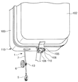
そして、作業員Sは、まず、図13・図14に示すように、対象となる電力量計器101を確認して、その電力量計器101を設置している電力量計器箱113の蓋箱102を取り外すのであるが、この蓋箱102を取り外す作業が、非常に面倒であった。
Then, as shown in FIGS. 13 and 14, the worker S first confirms the target watt-
即ち、電力量計器箱113の下部においては、図16(b)に示すように、電力量計器101を設置している固定箱103と、蓋箱102が、封印された状態で接合しており、電力量計器101を設置している固定箱103が、蓋箱102により閉鎖された状態となっている。
That is, in the lower part of the watt
この固定箱103と蓋箱102の接合・封印は、図16(a)(b)に示すように、固定箱103側の固定ナット104に、蓋箱102側のボルト105をねじ込んでいる状態において、紐状のインシュロック部材106を、ボルト105の孔107、固定箱103側の板片108の孔109、蓋箱102側の板片110の孔111に貫挿させて結束したものである。
As shown in FIGS. 16A and 16B, the fixing and fixing of the
この様な固定箱103と蓋箱102の接合・封印を解除するには、作業員Sは、絶縁手袋100を手に装着している状態で、所定のカッターを用いてインシュロック部材106を切断してから、所定のドライバーを用いてボルト105を回して、固定ナット104からボルト105を引き抜くという細かい作業を、連続的に実施しなければならない。
In order to release such joining / sealing between the
また、作業員Sは、絶縁手袋100を手に装着している状態で、蓋箱102を取り外して電力量計器箱113を開放し、固定箱103に設置している電力量計器101を露出させた後に、図15に示すように、所定のドライバーを用いて、電力量計器101に固定されている端子カバー112を取り外す作業も実施しなければならない。
In addition, while wearing the
次に、作業員Sは、図17に示すように、電力量計器101のDT端子・SG端子に、パソコン(PC)側のコード200の端子を接続して、当該電力量計器101における計量データの採録を行っていた。
Next, as shown in FIG. 17, the worker S connects the terminal of the
尚、電力量計器101の計量データの採録を終えたときは、パソコン(PC)側のコード200の端子を外して、端子カバー112を取り付ける作業を再度実施しなければならない。
In addition, when the collection of the measurement data of the
また、図16(a)(b)に示すように、固定箱103に蓋箱102を接合させ、固定箱103側の固定ナット104に蓋箱102側のボルト105をねじ込んでから、ボルト105の孔107、固定箱103側の板片108の孔109、蓋箱102側の板片110の孔111にインシュロック部材106を貫挿させて結束し、固定箱103と蓋箱102を再封印しなければならなかった。
Further, as shown in FIGS. 16A and 16B, the
この様に、作業員Sは、手に絶縁手袋100を装着して、指の感覚が通常よりも若干鈍っている状態において、前記したような細かい作業を連続的に実施しなければならない為、作業時間が長くなると共に、作業員Sが疲労してしまう要因となっていた。
In this way, since the worker S has to wear the
この様な作業の煩雑さは、パソコン(PC)側のコード200の端子を、電力量計器101の固定箱103側のDT端子・SG端子に接続する際に、閉鎖された状態となっている電力量計器箱113において、封印された状態で接合している固定箱103と蓋箱102に対し、その都度、封印を解いて蓋箱102を取り外さなければならないことに起因している。
The complexity of such work is in the closed state when the terminal of the
さらに、作業員Sは、比較的に狭い場所において前記したような細かい作業を連続的に実施しなければならない為、電力量計器箱113の近傍に存在している高圧充電部・低圧充電部に、コード200の端子等を接触させてしまう可能性もある。
Furthermore, since the worker S must continuously carry out the above-mentioned fine work in a relatively small place, the worker S has a high-voltage charging unit / low-voltage charging unit existing near the
この他、特許文献1に示すように、所定のデータを読み取る為に、端子台に測定クリップを適宜取り付ける技術を、電力量計器の計量データの採録に適用することも可能である。
In addition, as shown in
しかし、測定クリップを所定の位置に取り付けるために、閉鎖された状態となっている電力量計器箱113において、封印された状態で接合している固定箱103と蓋箱102に対し、その都度、封印を解いて蓋箱102を取り外さなければならないことに変わりはない。
However, in order to attach the measurement clip to a predetermined position, in the
また、測定クリップが金属であることから、電力量計器箱113の近傍に存在している高圧充電部・低圧充電部に接触して、様々な事故が発生してしまう可能性もある。
In addition, since the measurement clip is made of metal, various accidents may occur due to contact with the high-voltage charging unit / low-voltage charging unit existing in the vicinity of the
そこで、本発明は、如上のような従来存した諸事情に鑑み創出されたもので、閉鎖された状態となっている電力量計器箱の内部に、電力量計器の計量データ採録用の接続コードを予め配置しておき、必要なときにこの接続コードを電力量計器箱の外側に引き出すことにより、封印された状態で接合している固定箱と蓋箱に対し、蓋箱を取り外すことなく、電力量計器の計量データを採録することのできる、電力量計器箱の内部に配置する、電力量計器の計量データ採録用の接続コードと、この電力量計器の計量データ採録用の接続コードを使用した、電力量計器の計量データ採録方法を提供することを目的とする。 Therefore, the present invention was created in view of the existing circumstances as described above, and a connection cord for collecting measurement data of the watt hour meter inside the watt hour meter box in a closed state. Is placed in advance, and by pulling out this connection cord to the outside of the electricity meter box when necessary, it is possible to remove the lid box from the fixed box and the lid box that are joined in a sealed state. Use the connection cord for collecting the measurement data of the energy meter and the connection code for acquiring the measurement data of this energy meter, which is placed inside the energy meter box that can collect the measurement data of the energy meter. Another object of the present invention is to provide a method for collecting metering data for an electric energy meter.
本発明は、内部に電力量計器を設置して、全体として閉鎖状態となっている箱体に所定の孔を設けて電力量計器箱を構成し、電力量計器の端子に接続した状態で、電力量計器箱の内部に配置する、電力量計器の計量データ採録用の接続コードであり、
所定の長さの複数本の導線により構成され、複数本の導線の先端部に、所定形状の裸圧着端子を取り付けると共に、複数本の導線の基端部に、短絡コネクタを取り付け、複数本の導線の基端部側の適位置に、柔軟性を有するゴムブッシングを備え、
電力量計器の端子に裸圧着端子を接続した状態で、電力量計器箱を構成している箱体の孔に、ゴムブッシングを箱体の内部側から嵌合させていることで、上述した課題を解決した。
In the present invention, an electric energy meter is installed inside, a predetermined hole is provided in a box that is in a closed state as a whole to constitute an electric energy meter box, and connected to a terminal of the electric energy meter. It is a connection cord for collecting the metering data of the energy meter to be placed inside the energy meter box.
It is composed of a plurality of conductors of a predetermined length, and a bare crimp terminal having a predetermined shape is attached to the tip of the plurality of conductors, and a short-circuit connector is attached to the base end part of the plurality of conductors. Provided with a flexible rubber bushing at an appropriate position on the base end side of the conductor,
In the state where the bare crimping terminal is connected to the terminal of the watt hour meter, the rubber bushing is fitted from the inside of the box to the hole of the box constituting the watt hour meter box. Solved.
また、電力量計器箱を構成している箱体の孔に嵌合しているゴムブッシングは、箱体の外側に向けて適宜取り外し可能であり、導線の基端部に取り付けている短絡コネクタを、箱体の外側に引き出すことで、同じく上述した課題を解決した。 In addition, the rubber bushing fitted in the hole of the box constituting the watt hour meter box can be appropriately removed toward the outside of the box, and a short-circuit connector attached to the base end of the conductor is provided. The problem mentioned above was solved by pulling it out of the box.
この他、本発明に係る電力量計器の計量データ採録方法は、前記した電力量計器箱の内部に配置する、電力量計器の計量データ採録用の接続コードを使用することで、同じく上述した課題を解決した。 In addition, the metering data collecting method of the watt hour meter according to the present invention uses the connection cord for collecting the metering data of the watt hour meter, which is disposed inside the watt hour meter box described above. Solved.
また、電力量計器箱の内部に配置する、電力量計器の計量データ採録用の接続コードに、中間接続コードを接続し、この中間接続コードにパソコン(PC)側のコードを接続したことで、同じく上述した課題を解決した。 In addition, by connecting the intermediate connection cord to the connection cord for collecting the metering data of the watt hour meter to be placed inside the watt hour meter box, and connecting the cord on the personal computer (PC) side to this intermediate connection cord, The problem mentioned above was also solved.
さらに、電力量計器箱の内部に配置する、電力量計器の計量データ採録用の接続コードに、パソコン(PC)側のコードを接続したことで、同じく上述した課題を解決した。 Furthermore, the above-mentioned problem was solved by connecting the cord on the personal computer (PC) side to the connecting cord for collecting the metering data of the watt hour meter disposed inside the watt hour meter box.
本発明は、内部に電力量計器を設置して、全体として閉鎖状態となっている箱体に所定の孔を設けて電力量計器箱を構成し、電力量計器の端子に接続した状態で、電力量計器箱の内部に配置する、電力量計器の計量データ採録用の接続コードであり、
所定の長さの複数本の導線により構成され、複数本の導線の先端部に、所定形状の裸圧着端子を取り付けると共に、複数本の導線の基端部に、短絡コネクタを取り付け、複数本の導線の基端部側の適位置に、柔軟性を有するゴムブッシングを備え、
電力量計器の端子に裸圧着端子を接続した状態で、電力量計器箱を構成している箱体の孔に、ゴムブッシングを箱体の内部側から嵌合させていることから、通常は、電力量計器を内部に設置している電力量計器箱の閉鎖した状態を維持している。
In the present invention, an electric energy meter is installed inside, a predetermined hole is provided in a box that is in a closed state as a whole to constitute an electric energy meter box, and connected to a terminal of the electric energy meter. It is a connection cord for collecting the metering data of the energy meter to be placed inside the energy meter box.
It is composed of a plurality of conductors of a predetermined length, and a bare crimp terminal having a predetermined shape is attached to the tip of the plurality of conductors, and a short-circuit connector is attached to the base end part of the plurality of conductors. Provided with a flexible rubber bushing at an appropriate position on the base end side of the conductor,
Since the rubber bushing is fitted from the inside of the box to the hole of the box constituting the energy meter box with the bare crimp terminal connected to the terminal of the energy meter, The electricity meter box in which the electricity meter is installed is kept closed.
そして、電力量計器箱を構成している箱体の孔に嵌合しているゴムブッシングは、箱体の外側に向けて適宜取り外し可能であり、導線の基端部に取り付けている短絡コネクタを、箱体の外側に引き出すことができることから、この引き出した短絡コネクタを介して、当該電力量計器の計量データを適宜採録することができる。 And the rubber bushing fitted in the hole of the box constituting the watt-hour meter box can be appropriately removed toward the outside of the box, and the short-circuit connector attached to the base end of the conducting wire Since it can be pulled out to the outside of the box, the measurement data of the electric energy meter can be appropriately recorded through the pulled-out short-circuit connector.
このとき、電力量計器箱の閉鎖した状態を維持したまま、電力量計器の計量データを採録できることから、従来の採録作業で実施していた、電力量計器箱を構成している固定箱と蓋箱の接合・封印を解除する作業(作業員が絶縁手袋を手に装着している状態で行う、カッターを用いてインシュロック部材を切断してから、所定のドライバーを用いてボルトを回して、固定ナットからボルトを引き抜く細かい作業)を省くことができる。 At this time, the metering data of the watt hour meter can be collected while maintaining the closed state of the watt hour meter box. Therefore, the fixed box and the lid constituting the watt hour meter box, which has been performed in the conventional collecting operation, are performed. Work to release the joint / sealing of the box (when the worker wears insulating gloves on his / her hand, cut the insulation lock member with a cutter, and then turn the bolt with a specified screwdriver to fix it. The detailed work of pulling out the bolt from the nut can be omitted.
また、データの採録後に、固定箱に蓋箱を再封印する作業(作業員が絶縁手袋を手に装着している状態で行う、固定箱に蓋箱を接合させ、固定箱側の固定ナットに蓋箱側のボルトをねじ込んでから、ボルトの孔、固定箱側の板片の孔、蓋箱側の板片の孔にインシュロック部材を貫挿させて結束する細かい作業)も省くことができる。 In addition, after data is collected, the lid box is resealed to the fixed box (with the worker wearing insulating gloves on the hand, the lid box is joined to the fixed box, and the fixed nut on the fixed box side is attached. After screwing the bolt on the lid box side, it is possible to omit the fine work of inserting and binding the insulating lock member into the hole of the bolt, the hole of the plate piece on the fixed box side, and the hole of the plate piece on the lid box side.
その結果、閉鎖状態となっている電力量計器箱の内部に設置している電力量計器の計量データを採録する作業時間を大幅に短縮できると共に、作業員の労力も軽減することができる。 As a result, it is possible to greatly reduce the work time for collecting the metering data of the watt hour meter installed inside the watt hour meter box that is in the closed state, and to reduce the labor of the worker.
さらに、電力量計器箱の近傍に存在している高圧充電部・低圧充電部に、コードの端子等を接触させてしまう事態の発生も阻止して、作業の安全を確保している。 Furthermore, the occurrence of a situation in which the terminal of the cord or the like is brought into contact with the high-voltage charging unit / low-voltage charging unit existing in the vicinity of the watt-hour meter box is prevented, thereby ensuring work safety.
この他、本発明に係る電力量計器の計量データ採録方法においては、電力量計器箱の内部に配置する、電力量計器の計量データ採録用の接続コードを使用することにより、電力量計器箱の閉鎖した状態を維持したまま、電力量計器の計量データを簡単・迅速に採録できる。 In addition, in the metering data collecting method of the watt hour meter according to the present invention, the connection cord for collecting the metering data of the watt hour meter, which is arranged inside the watt hour meter box, is used. The metering data of the electricity meter can be recorded easily and quickly while maintaining the closed state.
また、電力量計器箱の内部に配置する、電力量計器の計量データ採録用の接続コードに、中間接続コードを接続し、この中間接続コードにパソコン(PC)側のコードを接続したときには、このパソコン(PC)により、電力量計器の計量データを確実に採録できる。 In addition, when an intermediate connection cord is connected to the connection cord for collecting the metering data of the watt hour meter, which is placed inside the watt hour meter box, and the PC (PC) side cord is connected to this intermediate connection cord, The metering data of the electricity meter can be reliably recorded by a personal computer (PC).
さらに、電力量計器箱の内部に配置する、電力量計器の計量データ採録用の接続コードに、パソコン(PC)側のコードを接続したときには、中間接続コードを省いた状態で、このパソコン(PC)により、電力量計器の計量データを確実に採録できる。 In addition, when the cord on the personal computer (PC) side is connected to the connection cord for collecting the metering data of the watt hour meter that is placed inside the watt hour meter box, this personal computer (PC ), The metering data of the energy meter can be reliably recorded.
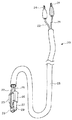
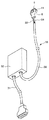
本発明に係る電力量計器箱113の内部に配置する、電力量計器101の計量データ採録用の接続コード1は、図1に示すように、所定の長さの複数本の導線(2,3)により構成されており、複数本の導線(2,3)の先端部に、所定形状の裸圧着端子4を取り付けている。また、複数本の導線(2,3)の基端部に、導線(2,3)の数に対応した複数極を備えている短絡コネクタ(雄)5を取り付けている。
As shown in FIG. 1, the
導線(2,3)の先端部に取り付けている裸圧着端子4、例えば、図1に示すように、棒状に形成されている。尚、裸圧着端子4の形状は、電力量計器101のDT端子・SG端子に接続可能であれば、どのような形状であっても差し支えない。
A
また、図1に示す接続コード1は、2本の導線2,3により構成されているが、これに限定されることはなく、接続コード1を、3本や4本以上の導線により構成しても良い。
The connecting
さらに、2本の導線2,3の基端部側(短絡コネクタ(雄)5側)の適位置に、柔軟性を有するゴムブッシング6を備えている。
Furthermore, the
所定の長さの2本の導線2,3は、その両端部分を除いた全体が、所定の絶縁シース7により被覆されている。
The two
2本の導線2,3の基端部に取り付けている2極の短絡コネクタ(雄)5は、図1に示すように、所定の長さを有する四角柱状に形成された絶縁ハウジング8を備えている。また、絶縁ハウジング8の内部には、その長手方向に沿うように、丸状中空部9と角状中空部10が設けられている。この丸状中空部9内には、導線2に接続しているピンが配置されている。また、角状中空部10内には、導線3に接続しているピンが配置されている。さらに、絶縁ハウジング8の端部には、一対の摘まみ片11が設けられている。また、絶縁ハウジング8の側面には、所定の突部16が設けられている。
A two-pole short-circuit connector (male) 5 attached to the base ends of the two
柔軟性を有するゴムブッシング6は、図1に示すように、所定の厚みを有する円盤状に形成され、その外周面に沿うように、凹溝12を設けている。このゴムブッシング6は、リング状の接続具13を介して、2本の導線2,3を被覆している絶縁シース7に取り付けられている。
As shown in FIG. 1, the
このゴムブッシング6は、図2・図4(a)(b)に示すように、電力量計器101を内部に設置している電力量計器箱103に取り付けるものである。具体的には、ゴムブッシング6は、電力量計器箱101を構成する固定箱103の所定の位置に設けられている円形の孔14に嵌合し、孔14を閉鎖している。
As shown in FIGS. 2 and 4 (a) and 4 (b), the
この固定箱103の孔14は、例えば、図4(b)(c)・図5に示すように、固定箱103における底板部分の端部寄りに設けられている。
The
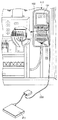
そして、電力量計器箱113の内部への、電力量計器101の計量データ採録用の接続コード1の取り付けは、まず、図2に示すように、電力量計器箱113を構成する蓋箱102を取り外して固定箱103を開放し、電力量計器101を露出させた状態とする。
Then, the attachment of the
次に、計量データ採録用の接続コード1を構成する棒状の裸圧着端子4を、電力量計器101のDT端子・SG端子に接続する。
Next, the rod-shaped
また、2本の導線2,3を被覆している絶縁シース7に取り付けられているゴムブッシング6を、図2に示すように、固定箱103の孔14に、固定箱103の内部側から嵌合させる。
Further, the
このとき、2本の導線2,3を被覆している絶縁シース7と、棒状の裸圧着端子4、2極の短絡コネクタ(雄)5は、固定箱103の内部に位置した状態となっている。
At this time, the insulating
また、絶縁シース7の裸圧着端子4側の適位置は、所定の取付具15を介して、固定箱103の側板に固定されている。同様に、絶縁シース7の短絡コネクタ(雄)5側の適位置も、所定の取付具15を介して、固定箱103の底板に固定されている。
In addition, the appropriate position of the insulating
この様に、固定箱103の内部に、電力量計器101の計量データ採録用の接続コード1を配置した状態で、図3に示すように、固定箱103に蓋箱102を宛がって固定し、電力量計器箱113を閉鎖した状態とする。
In this way, with the
電力量計器箱113の内部において、ゴムブッシング6は、自身の凹溝12を、固定箱103の孔14の周壁面に宛がい、孔14の周壁面に凹溝12を押し付けるようにして凹溝12内に孔14の周壁面を導入して、円盤状のゴムブッシング6を円形の孔14に嵌合させている。
Inside the watt
この様に、ゴムブッシング6を固定箱103の孔14に嵌合させたとき、ゴムブッシング6の上側の円形部分は、図2に示すように、固定箱103の内部に露出している。また、ゴムブッシング6の下側の円形部分は、図4(a)に示すように、固定箱103の外部に露出している。
As described above, when the
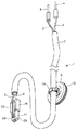
その為、電力量計器101を設置している電力量計器箱101を閉鎖している状態において、図4(a)に示すように、固定箱103の外部に露出しているゴムブッシング6の下側の円形部分を、指で摘んで下方に引っ張り、図4(b)(c)に示すように、固定箱103の孔14からゴムブッシング6を外部に向けて取り外すことができる。このとき、図4(c)・図5に示すように、2本の導線2,3を被覆している一部の絶縁シース7と一緒に、2極の短絡コネクタ(雄)5を固定箱103の外側に引き出すのである。
Therefore, in a state where the watt-
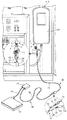
固定箱103の外側に引き出した2極の短絡コネクタ(雄)5には、中間接続コード20を接続し、この中間接続コード20にパソコン(PC)側のコード30を接続して、電力量計器101の計量データの採録を行う。
An
中間接続コード20は、図6に示すように、所定の長さの2本の導線21,22により構成され、2本の導線21,22の先端部に、2極の短絡コネクタ(雌)23を取り付けると共に、2本の導線21,22の基端部に、挟持クリップ24を取り付けている。
As shown in FIG. 6, the
所定の長さの2本の導線21,22は、その両端部分を除いた全体が、所定の絶縁シース25により被覆されている。
The two
2本の導線21,22の先端部に取り付けている2極の短絡コネクタ(雌)23は、短尺な四角柱状に形成された絶縁ハウジング26を備えている。絶縁ハウジング26の端部には、その長手方向に沿うように、円筒部27と角筒部28が並設されている。この円筒部27内には、導線21に接続しているソケットが配置されている。また、角筒部28内には、導線22に接続しているソケットが配置されている。さらに、絶縁ハウジング26の側面には、突出状に爪部29が設けられている。
A two-pole short-circuit connector (female) 23 attached to the distal ends of the two conducting
電力量計器101の計量データ採録用の接続コード1の短絡コネクタ(雄)5に、中間接続コード20の短絡コネクタ(雌)23を接続するときには、短絡コネクタ(雄)5の丸状中空部9に、短絡コネクタ(雌)23の円筒部27を挿入して、導線2に接続しているピンと、導線21に接続しているソケットを合致させる。同様に、短絡コネクタ(雄)5の角状中空部10に、短絡コネクタ(雌)23の角筒部28を挿入して、導線3に接続しているピンと、導線22に接続しているソケットを合致させる。
When connecting the short-circuit connector (female) 23 of the
この様に、短絡コネクタ(雄)5・短絡コネクタ(雌)23において、角状と丸状により、接合できる形状を限定していることにより、誤接続を防止している。また、ピンとソケットが、それぞれ絶縁ハウジング8,26に覆われているので、このピンとソケットが、電力量計器箱113の近傍に位置している充電部に、直接接的に接触することが無い。
Thus, in the short-circuit connector (male) 5 and the short-circuit connector (female) 23, the shapes that can be joined are limited by the square shape and the round shape, thereby preventing erroneous connection. Moreover, since the pin and the socket are respectively covered with the insulating
さらに、図7に示すように、計量データ採録用の接続コード1の短絡コネクタ(雄)5に、中間接続コード20の短絡コネクタ(雌)23を接続したとき、短絡コネクタ(雄)5の突部16に、短絡コネクタ(雌)23の爪部29が係合して、両者の離脱を阻止している。
Furthermore, as shown in FIG. 7, when the short-circuit connector (female) 23 of the
この様にして、計量データ採録用の接続コード1に、中間接続コード20を接続するのであるが、接続した中間接続コード20の端部には、パソコン(PC)側のコード30をさらに接続する。
In this way, the
パソコン(PC)側のコード30は、図8に示すように、パソコン(PC)に接続するケーブル31を備えている所定の変換器32から延設されている。この
コード30は、所定の長さの2本の導線33,34により構成され、2本の導線33,34の先端部に、棒状の裸圧着端子35を取り付けている。また、所定の長さの2本の導線33,34は、その先端部分を除いた全体が、所定の絶縁シース36により被覆されている。
As shown in FIG. 8, the
そして、中間接続コード20の端部に、パソコン(PC)側のコード30を接続するときは、図9に示すように、中間接続コード20の挟持クリップ24により、パソコン(PC)側のコード30における棒状の裸圧着端子35を挟み込むようにする。
When the personal computer (PC)
このとき、中間接続コード20において、導線21に接続している挟持クリップ24により、パソコン(PC)側のコード30における、導線33に接続している裸圧着端子35を挟み込むようにする。また、中間接続コード20において、導線22に接続している挟持クリップ24により、パソコン(PC)側のコード30における、導線34に接続している裸圧着端子35を挟み込むようにする。
At this time, in the
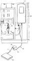
この様にして、図9に示すように、閉鎖されている状態の電力量計器箱101を構成している固定箱103の孔14から引き出されている接続コード1の2極の短絡コネクタ(雄)5に中間接続コード20の短絡コネクタ(雌)23を接続すると共に、中間接続コード20の挟持クリップ24により、パソコン(PC)側のコード30における棒状の裸圧着端子35を挟み込むことにより、中間接続コード20にパソコン(PC)側のコード30を接続する。この状態で、パソコン(PC)により、電力量計器101の計量データを採録するのである。
In this way, as shown in FIG. 9, the two-pole short-circuit connector (male) of the
尚、他の実施の形態として、中間接続コード20を省いて、計量データ採録用の接続コード1に、パソコン(PC)側のコード30を直接的に接続するものであっても良い。
As another embodiment, the
このとき、計量データ採録用の接続コード1は、図10に示すように、2本の導線2,3の基端部に、2極の短絡コネクタ(雌)23を取り付けておく。また、パソコン(PC)側のコード30は、図11に示すように、2本の導線33,34の先端部に、2極の短絡コネクタ(雄)5を取り付けておく。
At this time, the
そして、図12に示すように、計量データ採録用の接続コード1の2極の短絡コネクタ(雌)23に、パソコン(PC)側のコード30の2極の短絡コネクタ(雄)5を接続し、パソコン(PC)により、電力量計器101の計量データを採録するのである。
Then, as shown in FIG. 12, the two-pole short-circuit connector (male) 5 of the
尚、本発明は、前記した実施の形態に限定されるものではなく、本発明の目的を達成できる範囲での改良・変形等は、本発明に全て包含されるものである。 It should be noted that the present invention is not limited to the above-described embodiment, and all the improvements and modifications within the scope that can achieve the object of the present invention are included in the present invention.
本発明は、閉鎖された状態となっている電力量計器箱の内部から、接続コードを外側に適宜引き出して、電力量計器の計量データを採録するものであるが、電力量計器以外の、様々な機器のデータを採録するものとして、幅広く利用することができる。 In the present invention, the connection cord is appropriately pulled out from the inside of the watt hour meter box that is in a closed state, and the metering data of the watt hour meter is recorded. It can be used widely as a device for collecting data on various devices.
S…作業員
PC…パソコン
101…電力量計器
100…絶縁手袋
102…蓋箱
103…固定箱
104…固定ナット
105…ボルト
106…インシュロック部材
107…孔
108…板片
109…孔
110…板片
111…孔
112…端子カバー
113…電力量計器箱
200…パソコン側のコード
1…計量データ採録用の接続コード
2…導線
3…導線
4…裸圧着端子
5…短絡コネクタ(雄)
6…ゴムブッシング
7…絶縁シース
8…絶縁ハウジング
9…丸状中空部
10…角状中空部
11…摘まみ片
16…突部
12…凹溝
13…接続具
14…孔
15…取付具
20…中間接続コード
21…導線
22…導線
23…短絡コネクタ(雌)
24…挟持クリップ
25…絶縁シース
26…絶縁ハウジング
27…円筒部
28…角筒部
29…爪部
30…パソコン側のコード
31…ケーブル
32…変換器
33…導線
34…導線
35…裸圧着端子
36…絶縁シース
S ... Worker PC ...
DESCRIPTION OF
6 ...
24 ... Clipping
Claims (5)
所定の長さの複数本の導線により構成され、複数本の導線の先端部に、所定形状の裸圧着端子を取り付けると共に、複数本の導線の基端部に、短絡コネクタを取り付け、複数本の導線の基端部側の適位置に、柔軟性を有するゴムブッシングを備え、
電力量計器の端子に裸圧着端子を接続した状態で、電力量計器箱を構成している箱体の孔に、ゴムブッシングを箱体の内部側から嵌合させていることを特徴とする、電力量計器箱の内部に配置する、電力量計器の計量データ採録用の接続コード。 A watt hour meter box is installed with a predetermined hole in the box that is closed as a whole to form a watt hour meter box and connected to the terminal of the watt hour meter. Is a connection cord for collecting metering data of electricity meters,
It is composed of a plurality of conductors of a predetermined length, and a bare crimp terminal having a predetermined shape is attached to the tip of the plurality of conductors, and a short-circuit connector is attached to the base end part of the plurality of conductors. Provided with a flexible rubber bushing at an appropriate position on the base end side of the conductor,
With the bare crimping terminal connected to the terminal of the energy meter, a rubber bushing is fitted from the inside of the box to the hole of the box constituting the energy meter box, A connection cord for collecting metering data of watt hour meters placed inside the watt hour meter box.
Priority Applications (1)
| Application Number | Priority Date | Filing Date | Title |
|---|---|---|---|
| JP2011063752A JP2012198166A (en) | 2011-03-23 | 2011-03-23 | Connection cord arranged in watt-hour meter box to record measuring data of watt-hour meter, and method for recording measuring data of watt-hour meter by using connection cord for recording measuring data of watt-hour meter |
Applications Claiming Priority (1)
| Application Number | Priority Date | Filing Date | Title |
|---|---|---|---|
| JP2011063752A JP2012198166A (en) | 2011-03-23 | 2011-03-23 | Connection cord arranged in watt-hour meter box to record measuring data of watt-hour meter, and method for recording measuring data of watt-hour meter by using connection cord for recording measuring data of watt-hour meter |
Publications (1)
| Publication Number | Publication Date |
|---|---|
| JP2012198166A true JP2012198166A (en) | 2012-10-18 |
Family
ID=47180533
Family Applications (1)
| Application Number | Title | Priority Date | Filing Date |
|---|---|---|---|
| JP2011063752A Withdrawn JP2012198166A (en) | 2011-03-23 | 2011-03-23 | Connection cord arranged in watt-hour meter box to record measuring data of watt-hour meter, and method for recording measuring data of watt-hour meter by using connection cord for recording measuring data of watt-hour meter |
Country Status (1)
| Country | Link |
|---|---|
| JP (1) | JP2012198166A (en) |
Cited By (3)
| Publication number | Priority date | Publication date | Assignee | Title |
|---|---|---|---|---|
| CN105388342A (en) * | 2015-11-12 | 2016-03-09 | 杭州厚域科技有限公司 | High-conductivity plugging bar of electric energy meter box plugging seat and plugging mechanism of high-conductivity plugging bar |
| CN109273874A (en) * | 2018-11-07 | 2019-01-25 | 国网四川省电力公司资阳供电公司 | A kind of wire connection device in ammeter box |
| CN116626354A (en) * | 2023-03-27 | 2023-08-22 | 佳源科技股份有限公司 | Direct current intelligent electric energy meter |
-
2011
- 2011-03-23 JP JP2011063752A patent/JP2012198166A/en not_active Withdrawn
Cited By (5)
| Publication number | Priority date | Publication date | Assignee | Title |
|---|---|---|---|---|
| CN105388342A (en) * | 2015-11-12 | 2016-03-09 | 杭州厚域科技有限公司 | High-conductivity plugging bar of electric energy meter box plugging seat and plugging mechanism of high-conductivity plugging bar |
| CN109273874A (en) * | 2018-11-07 | 2019-01-25 | 国网四川省电力公司资阳供电公司 | A kind of wire connection device in ammeter box |
| CN109273874B (en) * | 2018-11-07 | 2023-09-26 | 国网四川省电力公司资阳供电公司 | Wire connecting device located in ammeter box |
| CN116626354A (en) * | 2023-03-27 | 2023-08-22 | 佳源科技股份有限公司 | Direct current intelligent electric energy meter |
| CN116626354B (en) * | 2023-03-27 | 2023-11-03 | 佳源科技股份有限公司 | Direct current intelligent electric energy meter |
Similar Documents
| Publication | Publication Date | Title |
|---|---|---|
| EP1276177B1 (en) | Power cord connecting set | |
| US7086892B2 (en) | Live circuit indicator for plugs and receptacles | |
| TWM349117U (en) | Socket for communication cable | |
| SG137787A1 (en) | High speed data plug and method for assembling same | |
| US10020627B1 (en) | Watthour meter block with safety shield | |
| US20090078447A1 (en) | Cable, configuration with the cable, method of producing the cable, and apparatus for producing the cable | |
| JP2013546115A (en) | Battery pack connector | |
| US7148419B1 (en) | Pre-wired electrical receptacle | |
| JP2012198166A (en) | Connection cord arranged in watt-hour meter box to record measuring data of watt-hour meter, and method for recording measuring data of watt-hour meter by using connection cord for recording measuring data of watt-hour meter | |
| JP5235830B2 (en) | Low voltage electrical instrument cable connector | |
| US9620868B2 (en) | Compact electrical connection system | |
| JP6701894B2 (en) | Connector and wire harness | |
| JP5874048B2 (en) | Wire positioning member and plug using the same | |
| JP2002527877A (en) | Electrical cable connector | |
| GB2391722A (en) | Ground potential only adapter | |
| US10620242B2 (en) | Watthour meter block with safety shield | |
| JP2009041952A (en) | Measuring device | |
| JP4990610B2 (en) | Misconnection prevention / sealing device and watt-hour meter | |
| CA2411189A1 (en) | Arrangement for attaching a plug-in connector to a shielded electric line | |
| CN205374551U (en) | Electric energy meter clearance fit connector | |
| JP2005274203A (en) | Watt-hour meter | |
| JP2010118260A (en) | Connection terminal | |
| JP5295167B2 (en) | Electricity meter | |
| JP2010237052A (en) | Receptacle | |
| US10124749B2 (en) | Electrical cable and connector with internal temperature-sensing mechanism |
Legal Events
| Date | Code | Title | Description |
|---|---|---|---|
| A300 | Application deemed to be withdrawn because no request for examination was validly filed |
Free format text: JAPANESE INTERMEDIATE CODE: A300 Effective date: 20140603 |