JP2012197740A - Axial blower - Google Patents
Axial blower Download PDFInfo
- Publication number
- JP2012197740A JP2012197740A JP2011063107A JP2011063107A JP2012197740A JP 2012197740 A JP2012197740 A JP 2012197740A JP 2011063107 A JP2011063107 A JP 2011063107A JP 2011063107 A JP2011063107 A JP 2011063107A JP 2012197740 A JP2012197740 A JP 2012197740A
- Authority
- JP
- Japan
- Prior art keywords
- axial
- casing
- adapter
- blower
- axial blower
- Prior art date
- Legal status (The legal status is an assumption and is not a legal conclusion. Google has not performed a legal analysis and makes no representation as to the accuracy of the status listed.)
- Pending
Links
Images


Classifications
-
- F—MECHANICAL ENGINEERING; LIGHTING; HEATING; WEAPONS; BLASTING
- F04—POSITIVE - DISPLACEMENT MACHINES FOR LIQUIDS; PUMPS FOR LIQUIDS OR ELASTIC FLUIDS
- F04D—NON-POSITIVE-DISPLACEMENT PUMPS
- F04D29/00—Details, component parts, or accessories
- F04D29/66—Combating cavitation, whirls, noise, vibration or the like; Balancing
- F04D29/68—Combating cavitation, whirls, noise, vibration or the like; Balancing by influencing boundary layers
- F04D29/681—Combating cavitation, whirls, noise, vibration or the like; Balancing by influencing boundary layers especially adapted for elastic fluid pumps
-
- F—MECHANICAL ENGINEERING; LIGHTING; HEATING; WEAPONS; BLASTING
- F04—POSITIVE - DISPLACEMENT MACHINES FOR LIQUIDS; PUMPS FOR LIQUIDS OR ELASTIC FLUIDS
- F04D—NON-POSITIVE-DISPLACEMENT PUMPS
- F04D25/00—Pumping installations or systems
- F04D25/02—Units comprising pumps and their driving means
- F04D25/06—Units comprising pumps and their driving means the pump being electrically driven
- F04D25/0606—Units comprising pumps and their driving means the pump being electrically driven the electric motor being specially adapted for integration in the pump
- F04D25/0613—Units comprising pumps and their driving means the pump being electrically driven the electric motor being specially adapted for integration in the pump the electric motor being of the inside-out type, i.e. the rotor is arranged radially outside a central stator
-
- F—MECHANICAL ENGINEERING; LIGHTING; HEATING; WEAPONS; BLASTING
- F04—POSITIVE - DISPLACEMENT MACHINES FOR LIQUIDS; PUMPS FOR LIQUIDS OR ELASTIC FLUIDS
- F04D—NON-POSITIVE-DISPLACEMENT PUMPS
- F04D29/00—Details, component parts, or accessories
- F04D29/40—Casings; Connections of working fluid
- F04D29/52—Casings; Connections of working fluid for axial pumps
- F04D29/522—Casings; Connections of working fluid for axial pumps especially adapted for elastic fluid pumps
- F04D29/526—Details of the casing section radially opposing blade tips
-
- F—MECHANICAL ENGINEERING; LIGHTING; HEATING; WEAPONS; BLASTING
- F04—POSITIVE - DISPLACEMENT MACHINES FOR LIQUIDS; PUMPS FOR LIQUIDS OR ELASTIC FLUIDS
- F04D—NON-POSITIVE-DISPLACEMENT PUMPS
- F04D29/00—Details, component parts, or accessories
- F04D29/66—Combating cavitation, whirls, noise, vibration or the like; Balancing
- F04D29/68—Combating cavitation, whirls, noise, vibration or the like; Balancing by influencing boundary layers
- F04D29/681—Combating cavitation, whirls, noise, vibration or the like; Balancing by influencing boundary layers especially adapted for elastic fluid pumps
- F04D29/685—Inducing localised fluid recirculation in the stator-rotor interface
Landscapes
- Engineering & Computer Science (AREA)
- Mechanical Engineering (AREA)
- General Engineering & Computer Science (AREA)
- Structures Of Non-Positive Displacement Pumps (AREA)
Abstract
Description
実施形態は軸流送風機に関する。 The embodiment relates to an axial blower.
電子機器の冷却用として軸流送風機が用いられることが多い。電子機器に組み込まれる部品の発熱量は増大傾向にあり、軸流送風機の冷却効果を高める必要がある。冷却効果を高めるために、軸流送風機の回転数を高めたり、複数の軸流送風機を軸方向に重ねて配置し、高風圧化することが提案されている。 An axial blower is often used for cooling electronic devices. The amount of heat generated by components incorporated in electronic equipment tends to increase, and it is necessary to increase the cooling effect of the axial blower. In order to enhance the cooling effect, it has been proposed to increase the rotational speed of the axial blower or to arrange a plurality of axial blowers in the axial direction to increase the wind pressure.
このような軸流送風機が作動する際に発生する作動音は、回転数比の5〜6乗に比例して増大することが知られている。したがって、軸流送風機の回転数を増大すると、作動音も増大することとなる。 It is known that the operation sound generated when such an axial flow fan operates increases in proportion to the fifth to sixth power of the rotation speed ratio. Therefore, when the rotational speed of the axial blower is increased, the operating noise is also increased.
ここで、電子機器が一般オフィスや家庭で使用されると、電子機器内の軸流送風機の作動音が騒音となって問題となることがあり、軸流送風機の作動音を低減することが求められている。そこで、軸流送風機を二重反転式として動翼や静止翼の形状を工夫することにより作動音を低減することが提案されている(例えば、特許文献1参照。)。 Here, when an electronic device is used in a general office or home, the operating sound of the axial blower in the electronic device may become a noise and become a problem, and it is required to reduce the operating sound of the axial blower. It has been. In view of this, it has been proposed to reduce the operating noise by devising the shape of the moving blades and stationary blades with the axial flow fan as a counter-rotating type (see, for example, Patent Document 1).
軸流送風機は、設計段階において目標動作点が設定されており、目標動作点は組み込まれる機器のシステムインピーダンスに合わせて設定される。目標動作点は、軸流送風機が組み込まれる機器のシステムインピーダンスと、送風機の静圧−風量特性との交点として求められる作動条件である。軸流送風機が目標動作点で作動しているときは、空力性能が最も高い状態で作動する。そこで、軸流送風機が目標動作点で作動しているときに作動音が小さくなるような軸流送風機を用いることで、作動音がなるべく低くなるようにしている。 In the axial blower, a target operating point is set at the design stage, and the target operating point is set according to the system impedance of the device to be incorporated. The target operating point is an operating condition obtained as an intersection between the system impedance of a device in which the axial flow fan is incorporated and the static pressure-air volume characteristic of the fan. When the axial blower is operating at the target operating point, it operates with the highest aerodynamic performance. Therefore, the operation sound is made as low as possible by using an axial flow fan that reduces the operation sound when the axial flow fan is operating at the target operating point.
ところが、実際に軸流送風機を機器に組み込んだ際に機器のシステムインピーダンスが多少異なっていたりした場合、軸流送風機の実際の動作点が目標動作点からずれてしまう。この結果、軸流送風機の作動音が増大するおそれがある。軸流送風機の動作点を実際の機器のシステムインピーダンスに合わせるように軸流送風機の構造を変更することで調整することができる。例えば動翼や静翼の形状を変更することで、目標動作点をずらすことができる。 However, when the axial flow fan is actually incorporated into the device, if the system impedance of the device is somewhat different, the actual operating point of the axial flow fan will deviate from the target operating point. As a result, the operating noise of the axial blower may increase. It can be adjusted by changing the structure of the axial blower so that the operating point of the axial blower matches the system impedance of the actual device. For example, the target operating point can be shifted by changing the shape of the moving blade or the stationary blade.
しかし、軸流送風機の動翼や静翼の形状を機器のシステムインピーダンスに合わせて変更するためには、形状の異なる動翼や静翼を構成するケーシングを多数準備しておき、動翼や静翼の形状が異なる軸流送風機を機器に組み込みながら調整する必要がある。この作業には時間がかかりその分のコストが増大してしまう。また、形状の異なる動翼や静翼を準備しておくには、動翼やケーシングを成形するための金型を数多く準備する必要があり、多大なコストがかかってしまう。 However, in order to change the shape of the rotor blades or stationary blades of an axial flow fan according to the system impedance of the equipment, a large number of casings constituting the rotor blades and stator blades having different shapes are prepared. It is necessary to adjust the axial flow fan with different wing shapes while it is installed in the equipment. This operation takes time and increases the cost. In addition, in order to prepare moving blades and stationary blades having different shapes, it is necessary to prepare a large number of molds for forming the moving blades and the casing, resulting in a great cost.
そこで、簡単な構造の変更で軸流送風機の騒音を低減することのできる技術の開発が望まれている。 Therefore, it is desired to develop a technique that can reduce the noise of an axial blower by simply changing the structure.
一実施形態によれば、回転して空気流を発生させる動翼と、前記動翼が収容されたケーシングと、前記ケーシングの内面に嵌合する嵌合部を有し、前記ケーシングの内面に突起又は段差を形成し、前記ケーシングに着脱自在なアダプタとを有する軸流送風機が提供される。 According to one embodiment, the moving blade that rotates to generate an air flow, the casing that houses the moving blade, the fitting portion that fits to the inner surface of the casing, and the protrusion on the inner surface of the casing Alternatively, an axial blower having a step and having an adapter that is detachable from the casing is provided.
アダプタはケーシングに着脱自在である。機器毎に送風機本体を変更する必要が無く、各機器に最適なアダプタを選択することで騒音低減が図れるため、低コスト化が図れる。 The adapter is detachable from the casing. There is no need to change the blower body for each device, and noise can be reduced by selecting an optimum adapter for each device, so that the cost can be reduced.
次に、実施形態について図面を参照しながら説明する。 Next, embodiments will be described with reference to the drawings.
本発明者は、軸流送風機のケーシングの内面に突起や段差を設けることにより、ケーシング内を流れる空気に乱流を発生させると、作動音を低減することができることを見いだした。図1は乱流発生段差が設けられた軸流送風機の断面図である。 The present inventor has found that operating noise can be reduced by providing protrusions and steps on the inner surface of the casing of the axial blower to generate turbulent flow in the air flowing in the casing. FIG. 1 is a cross-sectional view of an axial blower provided with a turbulent flow generation step.
図1において、円筒状のケーシング2の内部に静翼4と動翼6が設けられている。動翼6が回転することで図1の矢印方向の空気流が発生する。
In FIG. 1, a stationary blade 4 and a moving blade 6 are provided inside a
図1に示す軸流送風機おいて、通常は円筒状の内面であるケーシング2の内面2aに段差(又は突起)が設けられている。この段差がケーシング2内を流れる空気に乱流を生じさせる。これにより、軸流送風機の静圧−風量特性が変化し、作動音を低減することができる。突起又は段差の部分に空気流がぶつかって乱流が発生し、乱流内で動翼6が回転することで軸流送風機の静圧−風量特性が変化し、作動音が変化(低減)するものと考えられる。
In the axial blower shown in FIG. 1, a step (or protrusion) is provided on the inner surface 2a of the
このように乱流を発生させるための突起や段差は、ケーシング2の内面2aに突起や段差ができるようにケーシング2を成形することで設けることができる。しかし、突起や段差をケーシング2の一部として成形した場合、突起の形状や段差の高さ等を変更するためには、ケーシング2全体を交換しなければならない。そこで、本発明者は、ケーシング2の内面2aは従来のままの円筒形状し、ケーシング2の内面2aにアダプタを取り付けて突起又は段差を設けることを考えた。
Protrusions and steps for generating turbulent flow can be provided by molding the
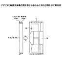
図2は段差を設けるためのアダプタを軸流送風機に組み込む前の状態を示す断面図であり、図3はアダプタを組み込んだ後の軸流送風機の断面図である。図4はアダプタを軸流送風機に組み込む前の状態を示す斜視図である。 FIG. 2 is a cross-sectional view showing a state before an adapter for providing a step is incorporated into an axial blower, and FIG. 3 is a cross-sectional view of the axial blower after the adapter is incorporated. FIG. 4 is a perspective view showing a state before the adapter is incorporated into the axial blower.
図2乃至図4に示す軸流送風機10は、円筒状のケーシング12の内面に支持部14が取り付けられ、支持部14の中央部分に動翼16の軸が支持された構造である。動翼16が回転すると図中矢印の方向に空気流が発生する。
The
図2乃至図4に示す構造では、アダプタ20は支持部14の側からケーシング12の内面12aに嵌め込まれる。アダプタ20は、ケーシング12の内面12aに嵌め込まれる円筒状の嵌合部20aと、嵌合部20aの一端側で嵌合部20aに対して垂直に延在するストッパ部20bとを有する。ストッパ部20bは、軸流送風機10の一端側のフランジ部10aとほぼ同じ形状であり、フランジ部10aに差し込まれるピン10bが挿入されるピン孔20cを有している。また、嵌合部20aは、支持部14をケーシングに固定する部分を避けるための切り欠き20dが設けられている。
In the structure shown in FIGS. 2 to 4, the
図3に示すようにアダプタ20の嵌合部20aをケーシング12の内面12aに嵌め込むと、ストッパ部20bは軸流送風機10のフランジ部10aに突き当たる。この状態で嵌合部20aの先端は動翼16の近傍に位置することとなり、嵌合部20aの先端部分により段差が形成される。この段差により動翼16の近傍に乱流を発生させる。
As shown in FIG. 3, when the
嵌合部20aの先端の位置はストッパ部20bが軸流送風機10のフランジ部10aに突き当たったときの位置であり、嵌合部20aの一端側にストッパ部20bを設けることにより、ケーシング12内での嵌合部20aの先端を精度よく位置決めすることができる。すなわち、ストッパ部20bが軸流送風機10のフランジ部10aに突き当たるまで嵌合部20aをケーシング12に挿入するだけで、嵌合部20aの先端を精度よく位置決めすることができ、ケーシング12の内面12aの精確な位置に段差を形成することができる。
The position of the tip of the
段差の高さ及び形状は図2、図3に示す高さ及び形状に限られず、乱流の発生具合をみながら変更することができる。段差の高さはアダプタ20の嵌合部20aの厚みに相当するので、嵌合部20aの厚みを変更することで段差の高さを調整することができる。また、段差の形状は、嵌合部20aの先端の形状に相当するので、嵌合部20aの先端部を図5(a)に示すように傾斜面としたり、図5(b)に示すように湾曲面とすることで、段差の形状を変更することができる。
The height and shape of the step are not limited to the height and shape shown in FIGS. 2 and 3 and can be changed while observing how the turbulence is generated. Since the height of the step corresponds to the thickness of the
図2、図3に示すアダプタ20は、軸流送風機10の支持部形成側からケーシング12に挿入するような形状となっているが、アダプタ20を反対側からケーシング12に挿入するような形状としてもよい。
The
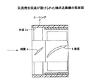
図6はアダプタ20を軸流送風機10の開放側からケーシング12に挿入する状態を示す断面図である。図6に示すアダプタ20Aは、開放側(空気が流入する側)から挿入するような形状となっている。具体的には、ケーシング12の内面12aに嵌合する嵌合部20Aaは、図2及び図3に示すアダプタ20の嵌合部20aより短くなっている。軸流送風機10の開放側には支持部が設けられていないので、その分だけ嵌合部20Aaの長さを短くして嵌合部20Aaの先端部が動翼16の近傍の所定の位置となるようにしている。また、嵌合部20Aaを挿入するときには、支持部14を通過させる必要が無いため、嵌合部20Aaに切り欠きを設ける必要は無く、円筒状のままでよい。
FIG. 6 is a cross-sectional view showing a state where the
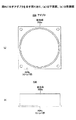
図7はアダプタ20Aを示す図であり、(a)は平面図、(b)は側面図である。アダプタ20Aは、アダプタ20と同様にストッパ部20Abを有しており、嵌合部20Aaをケーシング12に挿入する際に、ストッパ部がケーシング12の開放側端部に当接することで、嵌合部20Aaの先端部が所定の位置に配置される。
7A and 7B are views showing the
図8は、図2、図3に示すアダプタの変形例であるアダプタ20Bを示す図であり、(a)は平面図、(b)は側面図である。アダプタ20Bの嵌合部20Baはアダプタ20と同様に支持部14を通過するための切り欠き20dを有しているが、切り欠き20d以外にも切り欠き20dと同様な形状のスリット20Beが設けられている。したがって、アダプタ20Bの嵌合部20Baは、ストッパ部20Bbから延在する複数の短冊部20Bfにより形成されている。
8A and 8B are views showing an
ここで、動翼16の回転によりケーシング12の内面12aの付近に空気の旋回流が生じることがある。この場合、図8に示すアダプタ20Bのように軸方向に延在するスリット20Beにより短冊部20Bfが形成されていると、旋回流が短冊部20Bfと干渉して騒音の発生源となるおそれがある。そこで、図9に示すように、軸方向に対して傾斜したスリット20Cfを設けて傾斜した短冊部20Cfを形成してもよい。短冊部20Cfの傾斜角度は、動翼16の回転により発生する螺旋状の旋回流の角度に基づいて決定することで、旋回流と短冊部20Cfとの干渉を抑制することができ、旋回流に起因する騒音を抑制することができる。
Here, the rotation of the moving
なお、図10に示すように、上述のアダプタ(例えばアダプタ20A)に対して、指が軸流送風機に入らないようにするフィンガーガード30を設けることにより、アダプタにフィンガーガード機能を持たせることとしてもよい。
In addition, as shown in FIG. 10, by providing the finger guard 30 that prevents the fingers from entering the axial blower with respect to the above-described adapter (for example, the
次に、軸流送風機に組み込むアダプタの選定手順について、図11を参照しながら説明する。図11は軸流送風機に組み込むアダプタの選定手順のフローチャートである。 Next, a procedure for selecting an adapter to be incorporated into the axial fan will be described with reference to FIG. FIG. 11 is a flowchart of a procedure for selecting an adapter to be incorporated into the axial blower.
まず、機器に組み込む軸流送風機の特性を求め(S1)、且つ機器のシステムインピーダンス(機器内の空気流に対する抵抗損失)を求める(S2)。そして、軸流送風機の特性と機器のインピーダンスとにより、軸流送風機が機械に組み込まれた際に軸流送風機が動作する動作点を求め、その動作点における軸流送風機の作動音(騒音)を求める(S3)。次に、S3で求めた作動音が許容値以下あるか否かを判定し(S4)、作動音が許容値以下である場合は、作動音(騒音)を改善する必要は無いとして、その軸流送風機はそのまま完成品とする(S5)。一方、作動音が許容値を超えている場合は、作動音(騒音)を改善する必要があるとして、乱流発生用突起又は段差を形成する(S7)。このとき、乱流発生用突起又は段差を形成するためのアダプタを予め準備しておく(S6)。アダプタを軸流送風機にアダプタを取り付けたら、軸流送風機を機器に組み込んで作動音(騒音)を確認し、作動音(騒音)が許容値以下であったらそのアダプタを組み込んだ軸流送風機を完成品とする(S5)。 First, the characteristics of the axial blower incorporated in the device are obtained (S1), and the system impedance of the device (resistance loss against the air flow in the device) is obtained (S2). Based on the characteristics of the axial blower and the impedance of the equipment, the operating point at which the axial blower operates when the axial blower is incorporated into the machine is obtained, and the operating sound (noise) of the axial blower at the operating point is obtained. Obtain (S3). Next, it is determined whether or not the operating sound obtained in S3 is below the allowable value (S4). If the operating sound is below the allowable value, it is not necessary to improve the operating sound (noise), and the axis The air blower is used as it is as a finished product (S5). On the other hand, if the operating sound exceeds the allowable value, it is necessary to improve the operating sound (noise), and a turbulent flow generation projection or step is formed (S7). At this time, an adapter for forming a turbulent flow generation projection or a step is prepared in advance (S6). After mounting the adapter on the axial blower, install the axial blower into the equipment and check the operating noise (noise). If the operating noise (noise) is below the allowable value, complete the axial blower incorporating the adapter. (S5).
以上のアダプタの選定手順によれば、様々な形状のアダプタを準備しておき、いろいろと取り替えながら作動音を確認して、最適なアダプタを見つけることができる。このとき、上述のようにアダプタをケーシングに挿入して取り付けるだけで、乱流発生用突起又は段差を精確な位置に容易に形成することができる。また、アダプタをケーシングに挿入して嵌合するだけなので、異なる形状のアダプタに容易に交換することができ、短時間で容易に適切なアダプタを選定することができる。 According to the above adapter selection procedure, adapters of various shapes can be prepared, and the operation noise can be confirmed while being replaced in various ways to find the optimal adapter. At this time, the projection or step for generating turbulent flow can be easily formed at an accurate position simply by inserting and attaching the adapter to the casing as described above. Moreover, since the adapter is simply inserted into the casing and fitted, it can be easily replaced with an adapter having a different shape, and an appropriate adapter can be easily selected in a short time.
次に、上述の乱流発生用突起又は段差をケーシングの内面に形成したときの効果について簡単に説明する。上述の実施形態では、軸流送風機として一段式軸流送風機(シングルファン)に乱流発生用突起又は段差を形成しているが、動翼を軸方向に二段に重ねた二重反転式軸流送風機(二重反転ファン)に乱流発生用突起又は段差を形成してもよい。例えば、二重反転式軸流送風機の、互いに反対方向に回転する二つの動翼の間の位置に乱流発生用突起又は段差を形成することで、二段目の動翼の付近で乱流を発生させ、作動音を低減する。二重反転式軸流送風機は、通常、前段の送風機と後段の送風機間で分離が可能となっており、この場合のアダプタは後段動翼を形成する軸流送風機の支持部形成側から挿入しているが、開放側(空気が流出する側)から挿入しても良い。 Next, the effect when the above-described turbulent flow generation projection or step is formed on the inner surface of the casing will be briefly described. In the above-described embodiment, the turbulent flow generation projection or step is formed on the single-stage axial flow fan (single fan) as the axial flow blower, but the counter rotating shaft in which the moving blades are stacked in two stages in the axial direction. You may form the protrusion or level | step difference for turbulent flow generation | occurrence | production in a flow blower (a counter rotating fan). For example, by forming a turbulent flow generation projection or step at a position between two rotating blades rotating in opposite directions of a counter-rotating axial flow fan, turbulent flow near the second stage moving blade To reduce operating noise. The counter-rotating axial blower can normally be separated between the front blower and the rear blower, and the adapter in this case is inserted from the support forming side of the axial blower that forms the rear rotor blade. However, it may be inserted from the open side (air outflow side).
図12は、目標動作点が風量0.45m3/min、静圧300Paとなるように設計された既存の二重反転式軸流送風機(ノーマル(a))に対して、目標動作点を変えずに、4種類((b)乃至(e))の乱流発生用段差を形成した場合の作動音(騒音)と静圧−風量特性を示している。図12(a)において、「凸1mm」とは乱流発生用段差(半径方向の高低差)の寸法が1mmであることを意味する。図12(a)に示すように、目標動作点で作動音(騒音)が所定の音圧レベルとなるように、前段インペラ、後段インペラ及び中段静止部が設けられた二重反転式軸流送風機において、乱流発生用突出面(乱流発生用段差)を中段静止部の近傍に設けることは、作動音の増加原因となることがある。このような場合、図12(b)に示すように、目標動作点は変わっていない。 FIG. 12 shows that the target operating point is changed with respect to the existing counter-rotating axial flow fan (normal (a)) designed so that the target operating point has an air volume of 0.45 m 3 / min and a static pressure of 300 Pa. 4 shows the operating noise (noise) and static pressure-air volume characteristics when four types ((b) to (e)) of turbulent flow generation steps are formed. In FIG. 12A, “convex 1 mm” means that the dimension of the turbulent flow generation step (the height difference in the radial direction) is 1 mm. As shown in FIG. 12 (a), a counter-rotating axial flow fan provided with a front stage impeller, a rear stage impeller, and a middle stage stationary part so that the operating sound (noise) is at a predetermined sound pressure level at the target operating point. In this case, the provision of the turbulent flow generation projecting surface (turbulent flow generation step) in the vicinity of the middle stationary portion may cause an increase in operating noise. In such a case, the target operating point does not change as shown in FIG.
一方、図13は、目標動作点が風量0.45m3/min、静圧300Paとなるように設計された既存の二重反転式軸流送風機(ノーマル(a))を、風量0.4m3/min及び静圧320Paの目標動作点に変更した場合(ノーマル(a1))において、4種類((b1)乃至(e1))の乱流発生用段差を形成した場合の作動音(騒音)と静圧−風量特性を示している。図13(a)に示すように、目標動作点の風量を下げて使用するときは、径方向に0.2mmの高低差を有する乱流発生用突出面を設けると、乱流発生用突出面を設けない場合「ノーマル(a1)よりも作動音が低下する。これにより、前段インペラ、後段インペラ及び中段静止部の形状、寸法を変更せずに、乱流発生用突出面を設けるだけで作動音を低減できることがわかる。言い換えると、すでに特定の目標動作点で使用するために設計した軸流送風機の目標動作点が変更された場合に増大する作動音を、乱流発生用突出面(乱流発生用段差)を設けることにより低減できることを示している。 On the other hand, FIG. 13, the target operating point air volume 0.45 m 3 / min, the existing that are designed to be static pressure 300Pa counter-rotating axial-flow blower (Normal (a)), the air volume 0.4 m 3 When the target operating point is changed to / min and a static pressure of 320 Pa (normal (a1)), four types ((b1) to (e1)) of turbulent flow generation steps (noise) and The static pressure-air volume characteristic is shown. As shown in FIG. 13 (a), when the air flow at the target operating point is lowered and used, a turbulent flow generating projection surface having a height difference of 0.2 mm in the radial direction is provided. If it is not provided, the operating noise will be lower than that of normal (a1). As a result, the turbulent flow generating surface can be operated without changing the shape and dimensions of the front impeller, rear impeller, and middle stationary part. In other words, the operating noise that increases when the target operating point of an axial flow fan already designed for use at a specific target operating point is changed is reduced to the turbulent flow generating surface (turbulence). It can be reduced by providing a flow generation step).
以上の如く、本明細書は以下の事項を開示する。
(付記1)
回転して空気流を発生させる動翼と、
前記動翼が収容されたケーシングと、
前記ケーシングの内面に嵌合する嵌合部を有し、前記ケーシングの内面に突起又は段差を形成し、前記ケーシングに着脱自在なアダプタと、
を有する軸流送風機。
(付記2)
付記1に記載の軸流送風機であって、
前記嵌合部の一端側に形成され、前記ケーシングの軸方向に垂直な方向に延在するストッパ部
を有する軸流送風機。
(付記3)
付記1又は2に記載の軸流送風機であって、
前記アダプタの前記嵌合部は、前記ケーシングの軸方向に延在する複数の短冊部を含む軸流送風機。
(付記4)
付記1又は2に記載の軸流送風機であって、
前記アダプタの前記嵌合部は、前記ケーシングの軸方向に対して所定の角度だけ傾斜して延在する複数の短冊部を含む軸流送風機。
(付記5)
付記1乃至4のうちいずれか一項記載の軸流送風機であって、
前記ストッパ部は、前記ケーシングの空気流出側端部に当接している軸流送風機。
(付記6)
付記1乃至4のうちいずれか一項記載の軸流送風機であって、
前記ストッパ部は、前記ケーシングの空気流入側端部に当接している軸流送風機。
(付記7)
付記1乃至6のうちいずれか一項記載の軸流送風機であって、
前記嵌合部の先端部は、傾斜面又は湾曲面である軸流送風機。
(付記8)
付記1乃至7のうちいずれか一項記載の軸流送風機であって、
前記アダプタはフィンガーガードを有する軸流送風機。
As described above, the present specification discloses the following matters.
(Appendix 1)
A rotor blade that rotates to generate an air flow;
A casing in which the moving blade is housed;
An adapter that has a fitting portion that fits into the inner surface of the casing, forms a protrusion or a step on the inner surface of the casing, and an adapter that is detachable from the casing;
An axial flow blower with
(Appendix 2)
The axial flow fan according to appendix 1,
An axial blower having a stopper portion formed on one end side of the fitting portion and extending in a direction perpendicular to the axial direction of the casing.
(Appendix 3)
The axial flow fan according to
The fitting portion of the adapter is an axial blower including a plurality of strip portions extending in the axial direction of the casing.
(Appendix 4)
The axial flow fan according to
The fitting part of the adapter is an axial blower including a plurality of strips extending at a predetermined angle with respect to the axial direction of the casing.
(Appendix 5)
It is an axial flow fan given in any 1 paragraph of appendices 1 thru / or 4,
The stopper is an axial blower in contact with an air outflow side end of the casing.
(Appendix 6)
It is an axial flow fan given in any 1 paragraph of appendices 1 thru / or 4,
The stopper is an axial blower in contact with an air inflow side end of the casing.
(Appendix 7)
It is an axial flow fan given in any 1 paragraph of appendices 1 thru / or 6,
The axial flow fan in which the front-end | tip part of the said fitting part is an inclined surface or a curved surface.
(Appendix 8)
It is an axial flow fan given in any 1 paragraph of appendices 1 thru / or 7,
The adapter is an axial blower having a finger guard.
10 軸流送風機
10a フランジ部
10b ピン
12 ケーシング
12a 内面
14 支持部
16 動翼
20,20A,20B,20C アダプタ
20a,20Aa,20Ba,20Ca 嵌合部
20b,20Ab,20Bb,20Cb ストッパ部
20c ピン孔
20d 切り欠き
20Be,20Ce スリット
20Bf,20Cf 短冊部
DESCRIPTION OF
Claims (6)
前記動翼が収容されたケーシングと、
前記ケーシングの内面に嵌合する嵌合部を有し、前記ケーシングの内面に突起又は段差を形成し、前記ケーシングに着脱自在なアダプタと、
を有する軸流送風機。 A rotor blade that rotates to generate an air flow;
A casing in which the moving blade is housed;
An adapter that has a fitting portion that fits into the inner surface of the casing, forms a protrusion or a step on the inner surface of the casing, and an adapter that is detachable from the casing;
An axial flow blower with
前記嵌合部の一端側に形成され、前記ケーシングの軸方向に垂直な方向に延在するストッパ部
を有する軸流送風機。 The axial-flow fan according to claim 1,
An axial blower having a stopper portion formed on one end side of the fitting portion and extending in a direction perpendicular to the axial direction of the casing.
前記アダプタの前記嵌合部は、前記ケーシングの軸方向に延在する複数の短冊部を含む軸流送風機。 The axial blower according to claim 1 or 2,
The fitting portion of the adapter is an axial blower including a plurality of strip portions extending in the axial direction of the casing.
前記アダプタの前記嵌合部は、前記ケーシングの軸方向に対して所定の角度だけ傾斜して延在する複数の短冊部を含む軸流送風機。 The axial blower according to claim 1 or 2,
The fitting part of the adapter is an axial blower including a plurality of strips extending at a predetermined angle with respect to the axial direction of the casing.
前記ストッパ部は、前記ケーシングの空気流出側端部に当接している軸流送風機。 It is an axial blower as described in any one of Claims 1 thru | or 4, Comprising:
The stopper is an axial blower in contact with an air outflow side end of the casing.
前記ストッパ部は、前記ケーシングの空気流入側端部に当接している軸流送風機。 It is an axial blower as described in any one of Claims 1 thru | or 4, Comprising:
The stopper is an axial blower in contact with an air inflow side end of the casing.
Priority Applications (5)
| Application Number | Priority Date | Filing Date | Title |
|---|---|---|---|
| JP2011063107A JP2012197740A (en) | 2011-03-22 | 2011-03-22 | Axial blower |
| CN2012100745689A CN102691679A (en) | 2011-03-22 | 2012-03-20 | Axial blower |
| TW101109677A TW201241319A (en) | 2011-03-22 | 2012-03-21 | Axial blower |
| US13/425,688 US20120243985A1 (en) | 2011-03-22 | 2012-03-21 | Axial blower |
| EP12160575.2A EP2503159A3 (en) | 2011-03-22 | 2012-03-21 | Axial blower |
Applications Claiming Priority (1)
| Application Number | Priority Date | Filing Date | Title |
|---|---|---|---|
| JP2011063107A JP2012197740A (en) | 2011-03-22 | 2011-03-22 | Axial blower |
Publications (1)
| Publication Number | Publication Date |
|---|---|
| JP2012197740A true JP2012197740A (en) | 2012-10-18 |
Family
ID=45932158
Family Applications (1)
| Application Number | Title | Priority Date | Filing Date |
|---|---|---|---|
| JP2011063107A Pending JP2012197740A (en) | 2011-03-22 | 2011-03-22 | Axial blower |
Country Status (5)
| Country | Link |
|---|---|
| US (1) | US20120243985A1 (en) |
| EP (1) | EP2503159A3 (en) |
| JP (1) | JP2012197740A (en) |
| CN (1) | CN102691679A (en) |
| TW (1) | TW201241319A (en) |
Families Citing this family (5)
| Publication number | Priority date | Publication date | Assignee | Title |
|---|---|---|---|---|
| JP5256184B2 (en) * | 2009-12-14 | 2013-08-07 | 国立大学法人 東京大学 | Counter-rotating axial fan |
| DE102013223983A1 (en) * | 2013-11-25 | 2015-05-28 | Ebm-Papst Mulfingen Gmbh & Co. Kg | Lüfterbaueinheit |
| CA3056237A1 (en) | 2017-03-20 | 2018-09-27 | Shop Vac Corporation | Axial fan having housing formed by connectable pieces and including air guide ribs and an internal ramp |
| CN111980970B (en) * | 2020-08-31 | 2022-02-11 | 青岛顺威精密塑料有限公司 | Air outlet structure of axial fan |
| CN111911438B (en) * | 2020-09-24 | 2021-11-19 | 江西艾斯欧匹精密智造科技有限公司 | High heat dissipation fan convenient to dismouting |
Citations (7)
| Publication number | Priority date | Publication date | Assignee | Title |
|---|---|---|---|---|
| JPS63193795U (en) * | 1987-06-02 | 1988-12-13 | ||
| JPS63193792U (en) * | 1987-06-02 | 1988-12-13 | ||
| JPH0432300U (en) * | 1990-07-11 | 1992-03-16 | ||
| JPH0687695U (en) * | 1993-05-28 | 1994-12-22 | 西芝電機株式会社 | Axial blower |
| JPH08159099A (en) * | 1994-12-02 | 1996-06-18 | Hitachi Ltd | Axial flow fan |
| JP2007040110A (en) * | 2005-08-01 | 2007-02-15 | Calsonic Kansei Corp | Fan shroud structure of heat exchanger |
| JP2011122570A (en) * | 2009-12-14 | 2011-06-23 | Univ Of Tokyo | Contra-rotating axial blower |
Family Cites Families (20)
| Publication number | Priority date | Publication date | Assignee | Title |
|---|---|---|---|---|
| US3173605A (en) * | 1963-06-21 | 1965-03-16 | Rotron Mfg Co | Fan housing |
| US3178099A (en) * | 1963-10-09 | 1965-04-13 | Lachlan W Child | Under-body ventilating fan units |
| US4353680A (en) * | 1979-06-19 | 1982-10-12 | Tokyo Shibaura Denki Kabushiki Kaisha | Exhaust fan with removable face cover |
| US4750860A (en) * | 1986-06-30 | 1988-06-14 | Tandem Computers Incorporated | Fan |
| JP2635003B2 (en) * | 1993-12-28 | 1997-07-30 | 西芝電機株式会社 | Axial blower |
| JP3491342B2 (en) * | 1994-06-27 | 2004-01-26 | 松下電工株式会社 | Axial fan |
| CN2317434Y (en) * | 1997-12-31 | 1999-05-05 | 浙江上风实业股份有限公司 | Special blower for supercharging, ventilating and exhausting |
| US6254343B1 (en) * | 1999-12-06 | 2001-07-03 | Motorola, Inc. | Low-noise cooling fan for electronic components and method of making the same |
| JP4441978B2 (en) * | 2000-04-27 | 2010-03-31 | パナソニック株式会社 | Blower |
| JP2004293389A (en) * | 2003-03-26 | 2004-10-21 | Kyushu Hitachi Maxell Ltd | Hair dryer |
| GB2400141B (en) * | 2003-03-31 | 2005-01-19 | Sun Microsystems Inc | Fan grill |
| CN2720170Y (en) * | 2004-08-10 | 2005-08-24 | 沈阳鹭岛通风净化设备有限责任公司 | Novel silenced fan |
| JP4128194B2 (en) | 2005-09-14 | 2008-07-30 | 山洋電気株式会社 | Counter-rotating axial fan |
| US7658592B1 (en) * | 2005-12-29 | 2010-02-09 | Minebea Co., Ltd. | Slots in fan housing to reduce tonal noise |
| US20100247344A1 (en) * | 2006-12-18 | 2010-09-30 | Sheng-An Yang | Heat dissipating fan |
| CN201013674Y (en) * | 2006-12-29 | 2008-01-30 | 上海通用风机股份有限公司 | Noise deadener mounted in blower fan air inlet |
| US8087886B2 (en) * | 2007-06-13 | 2012-01-03 | Tek-Chain Technology Co., Ltd. | Sectional fan frame structure |
| JP2009127612A (en) * | 2007-11-28 | 2009-06-11 | Nippon Keiki Works Ltd | Venturi structure of fan motor |
| CN201486936U (en) * | 2009-06-10 | 2010-05-26 | 佛山市顺德区泛仕达机电有限公司 | Air inlet ring used for axial flow fan |
| CN201600635U (en) * | 2009-12-14 | 2010-10-06 | 鸿富锦精密工业(深圳)有限公司 | Wind shield and electronic device provided therewith |
-
2011
- 2011-03-22 JP JP2011063107A patent/JP2012197740A/en active Pending
-
2012
- 2012-03-20 CN CN2012100745689A patent/CN102691679A/en active Pending
- 2012-03-21 TW TW101109677A patent/TW201241319A/en unknown
- 2012-03-21 EP EP12160575.2A patent/EP2503159A3/en not_active Withdrawn
- 2012-03-21 US US13/425,688 patent/US20120243985A1/en not_active Abandoned
Patent Citations (7)
| Publication number | Priority date | Publication date | Assignee | Title |
|---|---|---|---|---|
| JPS63193795U (en) * | 1987-06-02 | 1988-12-13 | ||
| JPS63193792U (en) * | 1987-06-02 | 1988-12-13 | ||
| JPH0432300U (en) * | 1990-07-11 | 1992-03-16 | ||
| JPH0687695U (en) * | 1993-05-28 | 1994-12-22 | 西芝電機株式会社 | Axial blower |
| JPH08159099A (en) * | 1994-12-02 | 1996-06-18 | Hitachi Ltd | Axial flow fan |
| JP2007040110A (en) * | 2005-08-01 | 2007-02-15 | Calsonic Kansei Corp | Fan shroud structure of heat exchanger |
| JP2011122570A (en) * | 2009-12-14 | 2011-06-23 | Univ Of Tokyo | Contra-rotating axial blower |
Also Published As
| Publication number | Publication date |
|---|---|
| TW201241319A (en) | 2012-10-16 |
| CN102691679A (en) | 2012-09-26 |
| EP2503159A3 (en) | 2014-10-22 |
| EP2503159A2 (en) | 2012-09-26 |
| US20120243985A1 (en) | 2012-09-27 |
Similar Documents
| Publication | Publication Date | Title |
|---|---|---|
| JP5769978B2 (en) | Centrifugal fan | |
| JP5940266B2 (en) | Centrifugal fan and method of manufacturing centrifugal fan | |
| JP4994421B2 (en) | Centrifugal fan and air conditioner | |
| JP5273475B2 (en) | Inline axial fan | |
| JP5230805B2 (en) | Multi-blade blower | |
| JP5809859B2 (en) | Centrifugal fan | |
| US20080253897A1 (en) | Axial Flow Fan | |
| JP5705945B1 (en) | Centrifugal fan | |
| JP5728210B2 (en) | Axial fan | |
| JP5256184B2 (en) | Counter-rotating axial fan | |
| KR102143389B1 (en) | Circular Fan and Air Conditioner Having the Same | |
| JP2012197740A (en) | Axial blower | |
| JP2013130076A (en) | Impeller used for axial flow fan and axial flow fan using the same | |
| JP2009203897A (en) | Multi-blade blower | |
| JP6244547B2 (en) | Single suction centrifugal blower | |
| CN106104005A (en) | Air-blast device | |
| JP5682751B2 (en) | Multi-blade blower | |
| JP5705805B2 (en) | Centrifugal fan | |
| JP3130089U (en) | Centrifugal blower | |
| JP2006125229A (en) | Sirocco fan | |
| JP6588999B2 (en) | Centrifugal fan | |
| JP2014025426A (en) | Blower | |
| JP2017057858A (en) | Centrifugal fan | |
| JP2018150867A (en) | Centrifugal fan | |
| JP7466707B2 (en) | Centrifugal Blower |
Legal Events
| Date | Code | Title | Description |
|---|---|---|---|
| A621 | Written request for application examination |
Free format text: JAPANESE INTERMEDIATE CODE: A621 Effective date: 20140108 |
|
| A131 | Notification of reasons for refusal |
Free format text: JAPANESE INTERMEDIATE CODE: A131 Effective date: 20140909 |
|
| A977 | Report on retrieval |
Free format text: JAPANESE INTERMEDIATE CODE: A971007 Effective date: 20140911 |
|
| A521 | Request for written amendment filed |
Free format text: JAPANESE INTERMEDIATE CODE: A523 Effective date: 20141016 |
|
| A02 | Decision of refusal |
Free format text: JAPANESE INTERMEDIATE CODE: A02 Effective date: 20150407 |