JP2012197675A - Wind power generation apparatus and power generation system - Google Patents
Wind power generation apparatus and power generation system Download PDFInfo
- Publication number
- JP2012197675A JP2012197675A JP2011060593A JP2011060593A JP2012197675A JP 2012197675 A JP2012197675 A JP 2012197675A JP 2011060593 A JP2011060593 A JP 2011060593A JP 2011060593 A JP2011060593 A JP 2011060593A JP 2012197675 A JP2012197675 A JP 2012197675A
- Authority
- JP
- Japan
- Prior art keywords
- power
- solar cell
- generator
- housing
- wind
- Prior art date
- Legal status (The legal status is an assumption and is not a legal conclusion. Google has not performed a legal analysis and makes no representation as to the accuracy of the status listed.)
- Withdrawn
Links
Images


Classifications
-
- Y—GENERAL TAGGING OF NEW TECHNOLOGICAL DEVELOPMENTS; GENERAL TAGGING OF CROSS-SECTIONAL TECHNOLOGIES SPANNING OVER SEVERAL SECTIONS OF THE IPC; TECHNICAL SUBJECTS COVERED BY FORMER USPC CROSS-REFERENCE ART COLLECTIONS [XRACs] AND DIGESTS
- Y02—TECHNOLOGIES OR APPLICATIONS FOR MITIGATION OR ADAPTATION AGAINST CLIMATE CHANGE
- Y02B—CLIMATE CHANGE MITIGATION TECHNOLOGIES RELATED TO BUILDINGS, e.g. HOUSING, HOUSE APPLIANCES OR RELATED END-USER APPLICATIONS
- Y02B10/00—Integration of renewable energy sources in buildings
- Y02B10/10—Photovoltaic [PV]
-
- Y—GENERAL TAGGING OF NEW TECHNOLOGICAL DEVELOPMENTS; GENERAL TAGGING OF CROSS-SECTIONAL TECHNOLOGIES SPANNING OVER SEVERAL SECTIONS OF THE IPC; TECHNICAL SUBJECTS COVERED BY FORMER USPC CROSS-REFERENCE ART COLLECTIONS [XRACs] AND DIGESTS
- Y02—TECHNOLOGIES OR APPLICATIONS FOR MITIGATION OR ADAPTATION AGAINST CLIMATE CHANGE
- Y02B—CLIMATE CHANGE MITIGATION TECHNOLOGIES RELATED TO BUILDINGS, e.g. HOUSING, HOUSE APPLIANCES OR RELATED END-USER APPLICATIONS
- Y02B10/00—Integration of renewable energy sources in buildings
- Y02B10/70—Hybrid systems, e.g. uninterruptible or back-up power supplies integrating renewable energies
-
- Y—GENERAL TAGGING OF NEW TECHNOLOGICAL DEVELOPMENTS; GENERAL TAGGING OF CROSS-SECTIONAL TECHNOLOGIES SPANNING OVER SEVERAL SECTIONS OF THE IPC; TECHNICAL SUBJECTS COVERED BY FORMER USPC CROSS-REFERENCE ART COLLECTIONS [XRACs] AND DIGESTS
- Y02—TECHNOLOGIES OR APPLICATIONS FOR MITIGATION OR ADAPTATION AGAINST CLIMATE CHANGE
- Y02E—REDUCTION OF GREENHOUSE GAS [GHG] EMISSIONS, RELATED TO ENERGY GENERATION, TRANSMISSION OR DISTRIBUTION
- Y02E10/00—Energy generation through renewable energy sources
- Y02E10/50—Photovoltaic [PV] energy
-
- Y—GENERAL TAGGING OF NEW TECHNOLOGICAL DEVELOPMENTS; GENERAL TAGGING OF CROSS-SECTIONAL TECHNOLOGIES SPANNING OVER SEVERAL SECTIONS OF THE IPC; TECHNICAL SUBJECTS COVERED BY FORMER USPC CROSS-REFERENCE ART COLLECTIONS [XRACs] AND DIGESTS
- Y02—TECHNOLOGIES OR APPLICATIONS FOR MITIGATION OR ADAPTATION AGAINST CLIMATE CHANGE
- Y02E—REDUCTION OF GREENHOUSE GAS [GHG] EMISSIONS, RELATED TO ENERGY GENERATION, TRANSMISSION OR DISTRIBUTION
- Y02E10/00—Energy generation through renewable energy sources
- Y02E10/70—Wind energy
- Y02E10/74—Wind turbines with rotation axis perpendicular to the wind direction
Abstract
Description
本発明は、建物の屋根面等において太陽電池アレイと共に設置される風力発電装置、及びこの風力発電装置を有する発電システムに関する。 The present invention relates to a wind power generator installed together with a solar cell array on a roof surface of a building, and a power generation system having the wind power generator.
近年、地球温暖化対策の1つとして、二酸化炭素の発生がなく自然エネルギーにより発電する太陽光発電装置の普及が進んでいる(例えば特許文献1、2、3参照)。太陽光発電装置は、複数の太陽電池モジュールがアレイ状に配置された太陽電池アレイを備えており、この太陽電池アレイは、平地、建築物の屋上、住宅の屋根などに設置されている。
In recent years, as one of the countermeasures against global warming, a solar power generation apparatus that generates power using natural energy without generation of carbon dioxide has been spreading (see, for example,
平地や建築物の屋上等の平坦な場所では、太陽光発電装置の発電効率を向上させるために、架台を使用して、太陽光の角度を考慮した傾斜をつけて太陽電池アレイを設置している。また、太陽電池アレイを住宅の屋根に簡便に設置する方法として、金具で架台を屋根に固定し、この架台上に太陽電池アレイを設置する方法が知られている。 In a flat place such as a flat ground or a rooftop of a building, in order to improve the power generation efficiency of the photovoltaic power generation device, a solar cell array is installed with an inclination that takes into account the angle of sunlight using a mount. Yes. Further, as a method for easily installing the solar cell array on the roof of a house, a method is known in which a gantry is fixed to the roof with metal fittings and the solar cell array is installed on the gantry.
このように、従来の太陽電池アレイは架台上に設置されていたが、この架台部分のスペースは有効活用されていなかった。また、太陽光発電装置は悪天候や夜間等の日射のない時は発電できないため、このような時にも自然エネルギーを利用して発電を行うことが求められている。 Thus, although the conventional solar cell array was installed on the mount, the space of this mount was not effectively utilized. Moreover, since a solar power generation device cannot generate electric power when there is no bad weather or solar radiation such as at night, it is required to generate electric power using natural energy even in such a case.
本発明は、このような点を考慮してなされたものであり、太陽電池アレイを支持する架台部分のスペースを有効活用するとともに、日射のないときにも発電を行うことができる風力発電装置、及びこの風力発電装置を有する発電システムを提供することを目的とする。 The present invention has been made in consideration of such points, and while making effective use of the space of the gantry part that supports the solar cell array, the wind power generator capable of generating power even when there is no solar radiation, And it aims at providing the electric power generation system which has this wind power generator.
本発明(請求項1)の風力発電装置は、側面に開口部が設けられている筐体と、前記筐体内に収容されている風車と、前記風車の回転軸に連結された発電機と、前記筐体の上部に設けられ、所定の傾斜をつけて太陽電池アレイを支持することができる支持部と、を備えるものである。 A wind turbine generator according to the present invention (Claim 1) includes a casing provided with an opening on a side surface, a windmill housed in the casing, a generator connected to a rotating shaft of the windmill, A support portion provided on an upper portion of the housing and capable of supporting the solar cell array with a predetermined inclination.
本発明の一態様による風力発電装置においては、前記筐体又は前記支持部に取り付けられ、前記開口部への風量を調整する風量調整板をさらに備え、前記風車は垂直軸型風車である。 In the wind turbine generator according to an aspect of the present invention, the wind turbine is further provided with an air volume adjusting plate that is attached to the housing or the support and adjusts the air volume to the opening, and the wind turbine is a vertical axis wind turbine.
本発明の一態様による風力発電装置においては、前記発電機は、前記筐体の上面と前記支持部の載荷板との間に設けられる。 In the wind turbine generator according to an aspect of the present invention, the generator is provided between the upper surface of the casing and the loading plate of the support portion.
本発明(請求項4)の発電システムは、前記風力発電装置が水平方向に複数連結されているものである。 In the power generation system of the present invention (Claim 4), a plurality of the wind power generators are connected in the horizontal direction.
本発明(請求項5)の発電システムは、垂直方向に連結され、側面に開口部が設けられている複数の筐体と、前記複数の筐体内に収容されている複数の風車と、前記複数の風車の回転軸に連結された発電機と、最上段の筐体の上部に設けられ、所定の傾斜をつけて太陽電池アレイを支持することができる支持部と、を備えるものである。 The power generation system of the present invention (Claim 5) includes a plurality of casings that are connected in the vertical direction and that have openings on side surfaces, a plurality of windmills that are housed in the plurality of casings, and the plurality of windmills. A generator connected to the rotating shaft of the wind turbine, and a support portion provided on the uppermost casing and capable of supporting the solar cell array with a predetermined inclination.
本発明(請求項6)の発電システムは、側面に開口部が設けられている筐体と、前記筐体内に収容されている風車と、前記風車の回転軸に連結され、第1交流電力を発電する発電機と、太陽光を利用して第1直流電力を発電する太陽電池アレイと、前記筐体の上部に設けられ、所定の傾斜をつけて前記太陽電池アレイを支持する支持部と、前記第1交流電力を第2直流電力に変換するコントローラと、前記第1直流電力及び前記第2直流電力を充電する蓄電池と、前記蓄電池に充電されている直流電力を第2交流電力に変換して負荷に供給するインバータと、を備えるものである。 The power generation system of the present invention (Claim 6) is connected to a casing having an opening on a side surface, a windmill housed in the casing, and a rotating shaft of the windmill, and generates first AC power. A generator for generating electricity, a solar cell array for generating first direct-current power using sunlight, a support portion provided on an upper portion of the casing and supporting the solar cell array with a predetermined inclination; A controller that converts the first AC power into second DC power; a storage battery that charges the first DC power and the second DC power; and DC power that is charged in the storage battery is converted into second AC power. And an inverter for supplying the load to the load.
本発明の風力発電装置によれば、太陽電池アレイを支持する架台部分のスペースを有効活用するとともに、日射のないときにも発電を行うことができる。 According to the wind power generator of the present invention, it is possible to effectively utilize the space of the gantry portion that supports the solar cell array and to generate power even when there is no solar radiation.
以下、本発明の実施の形態を図面に基づいて説明する。 Hereinafter, embodiments of the present invention will be described with reference to the drawings.
図1に本発明の実施形態に係る風力発電装置の外観を示す。風力発電装置1は、風車10と、風車10の回転軸に連結された発電機12と、風車10を収容する筐体14と、太陽電池アレイ(図示せず)を支持可能な支持部16とを備えている。
FIG. 1 shows an external appearance of a wind turbine generator according to an embodiment of the present invention. The
風車10は、風向きに対して回転軸が垂直な垂直軸型風車であり、風向きの制御を必要としない。また、風車10を垂直軸型風車とすることで、太陽電池アレイを上方に載置することで筐体14内における風が乱れても、風車10を効率良く回転させることができる。風車10の回転軸の上端及び下端を軸承する軸受(図示略)は、筐体14の上面(天井部)と下面(底版部)にそれぞれ設けられている。発電機12は、風車10の回転により発電を行う。発電機12は、例えば筐体14の上面に設置することができる。
The
筐体14は、金属又は樹脂で形成された直方体形状の箱型になっており、4側面に開口部14aが設けられ、風が通り抜けるようになっている。
The
支持部16は、筐体14上に設けられている。該支持部16の上面部を構成する載荷板16aは、筐体14の上面に対して所定の傾斜角θをなしている。傾斜角θは、風力発電装置1の設置場所の緯度、及び支持部16上に支持される太陽電池アレイの構造に基づいて決定される。
The
支持部16は、金属又は合成樹脂で形成される。筐体14及び支持部16を形成する材料は同じでもよいし、異なっていてもよい。支持部16及び筐体14は、太陽電池アレイの荷重に耐えられる耐重量性能を有しているものとする。支持部16及び筐体14を構成する金属材料としては例えばアルミ、ステンレス等を使用することができ、合成樹脂材料としては耐候性に優れたものを使用する。
The
図1に示すように、筐体14には、開口部14aへの風量を調整するための風量調整板18がロック付きヒンジ(図示略)等により設置角度調節可能に設けられている。風量調整板18の角度を変えることで、風車10が受ける風量を調整することができる。この風量調整板18により、強風で風車10が故障することを防止できる。この風量調整板18は、支持部16に支持される太陽電池アレイに接触しないように設けられる。風量調整板18は支持部16に取り付けられていてもよい。
As shown in FIG. 1, the
このような風力発電装置1上に太陽電池アレイを載置した発電システムの外観を図2に示し、ブロック構成を図3に示す。
FIG. 2 shows an external appearance of a power generation system in which a solar cell array is placed on such a
図2に示すように、太陽電池アレイ20は、風力発電装置1の支持部16の載荷板16a上に設置される。太陽電池アレイ20は、複数の太陽電池モジュール(太陽電池パネル)を直並列に接続したものである。また、太陽電池モジュールは、太陽電池(セル)を複数枚直並列接続して必要な電圧及び電流を得られるようにしたものである。
As shown in FIG. 2, the
風力発電装置1の筐体10を住宅の屋根等に固定し、太陽電池アレイ20を支持部16に取り付けることで、太陽電池アレイ20を設置することができる。
The
図3に示すように、この発電システムは、太陽光発電及び風力発電による電力を、電気器具等の負荷50に供給するものである。太陽電池アレイ20で発電された直流電力は、太陽電池コントローラ30により負荷供給電力P1及び蓄電池充電電力P2になる。負荷供給電力P1は、インバータ(DC/AC)34により交流電力P3に変換され、負荷50に供給される。また、蓄電池充電電力P2は蓄電池36に充電される。
As shown in FIG. 3, this power generation system supplies electric power generated by solar power generation and wind power generation to a
風力発電装置1の発電機12により発電された交流電力は、風力発電コントローラ32により直流電力P4となり、蓄電池36に充電される。風力発電装置1の出力電力は、風の吹き具合によって不安定になり得るが、蓄電池36に一旦充電することで安定した出力となる。
The AC power generated by the
放電コントローラ38は、蓄電池36に充電された直流電力をインバータ(DC/AC)40を用いて交流電力P5に変換し、負荷50に供給する。
風力発電装置1は風が吹いているときは昼夜・天候を問わず発電することができる。そのため、この発電システムによれば、太陽光発電装置が発電できない悪天候や夜間等の日射のない時にも発電を行うことができる。
The
The
また、太陽電池アレイ20は、支持部16により所望の傾斜をつけて設置できるため、太陽電池アレイ20を太陽高度に合わせることができ、発電効率を向上させることができる。
Moreover, since the
また、本実施形態では、太陽電池アレイ20を支える筐体14部分に風車10を設けて風力発電装置1を構成する。そのため、従来デッドスペースとなっていた太陽電池アレイ20の架台部分を有効活用することができる。また、風力発電装置1の発電機12を、筐体14と支持部16の載荷板16aとの間の空間に設置しているので、支持部16の傾斜により生じる空間を有効活用することができる。
Further, in the present embodiment, the
図2では、発電機及び太陽電池アレイが1セットずつ設けられているが、本発明はこれに限定されるものではない。例えば、図4及び図5に示すように、水平方向に連結した複数の風力発電装置1の上に、太陽電池アレイ20を取り付けてもよい。さらに、図示は省略するが、このように水平方向に連結した複数の風力発電装置1を有する風力発電システムを互いに平行に複数配置してもよい。
In FIG. 2, the generator and the solar cell array are provided one by one, but the present invention is not limited to this. For example, as shown in FIGS. 4 and 5, the
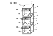
また、図6及び図7に示すように垂直方向に連結した複数の風力発電装置1の上に、太陽電池アレイ20を取り付けてもよい。なお、この場合、最上段以外の風力発電装置1は、支持部16を省略した構成となる。また、複数の風力発電装置1の風車10の回転軸を同一にし、この回転軸に発電機12が連結されるようにしてもよい。さらに、垂直方向に連結した複数の風力発電装置1を有する風力発電システムを互いに平行に複数配置してもよい。
Moreover, you may attach the
上記実施形態では、風車10として、サボニウス型風車やダリウス型風車など様々なタイプの垂直軸型風車を使用することができる。また、垂直軸型風車でなくプロペラ型風車のような水平軸型の風車を用いてもよい。プロペラ型風車では、風向きに対する制御が必要となるが、強風時に風を受け逃がす機構と併用することができ、その場合、風量調整板18を省略することができる。
In the above-described embodiment, various types of vertical axis wind turbines such as Savonius type wind turbines and Darrieus type wind turbines can be used as the
なお、本発明は上記実施形態に限定されるものではなく、その要旨を逸脱しない範囲で上記以外の種々の構成をとりうる。 In addition, this invention is not limited to the said embodiment, Various structures other than the above can be taken in the range which does not deviate from the summary.
1 風力発電装置
10 風車
12 発電機
14 筐体
16 支持部
18 風量調整板
20 太陽電池アレイ
30 太陽電池コントローラ
32 風力発電コントローラ
34 インバータ
36 蓄電池
38 放電コントローラ
40 インバータ
50 負荷
DESCRIPTION OF
Claims (6)
前記筐体内に収容されている風車と、
前記風車の回転軸に連結された発電機と、
前記筐体の上部に設けられ、所定の傾斜をつけて太陽電池アレイを支持することができる支持部と、
を備えた風力発電装置。 A housing having an opening on a side surface;
A windmill housed in the housing;
A generator connected to the rotating shaft of the windmill;
A support portion that is provided on an upper portion of the housing and can support the solar cell array with a predetermined inclination;
Wind power generator equipped with.
前記風車は垂直軸型風車であることを特徴とする請求項1に記載の風力発電装置。 An air volume adjusting plate that is attached to the housing or the support and adjusts the air volume to the opening;
The wind turbine generator according to claim 1, wherein the wind turbine is a vertical axis type wind turbine.
前記複数の筐体内に収容されている複数の風車と、
前記複数の風車の回転軸に連結された発電機と、
最上段の筐体の上部に設けられ、所定の傾斜をつけて太陽電池アレイを支持することができる支持部と、
を備えた発電システム。 A plurality of casings connected in a vertical direction and provided with openings on side surfaces;
A plurality of windmills housed in the plurality of housings;
A generator coupled to the rotating shafts of the plurality of wind turbines;
A support portion that is provided on the top of the uppermost housing and can support the solar cell array with a predetermined inclination;
Power generation system with
前記筐体内に収容されている風車と、
前記風車の回転軸に連結され、第1交流電力を発電する発電機と、
太陽光を利用して第1直流電力を発電する太陽電池アレイと、
前記筐体の上部に設けられ、所定の傾斜をつけて前記太陽電池アレイを支持する支持部と、
前記第1交流電力を第2直流電力に変換するコントローラと、
前記第1直流電力及び前記第2直流電力を充電する蓄電池と、
前記蓄電池に充電されている直流電力を第2交流電力に変換して負荷に供給するインバータと、
を備えた発電システム。 A housing having an opening on a side surface;
A windmill housed in the housing;
A generator coupled to the rotating shaft of the windmill for generating first AC power;
A solar cell array that generates first DC power using sunlight;
A support portion provided at an upper portion of the housing and supporting the solar cell array with a predetermined inclination;
A controller for converting the first AC power into second DC power;
A storage battery for charging the first DC power and the second DC power;
An inverter that converts the DC power charged in the storage battery into second AC power and supplies it to the load;
Power generation system with
Priority Applications (1)
| Application Number | Priority Date | Filing Date | Title |
|---|---|---|---|
| JP2011060593A JP2012197675A (en) | 2011-03-18 | 2011-03-18 | Wind power generation apparatus and power generation system |
Applications Claiming Priority (1)
| Application Number | Priority Date | Filing Date | Title |
|---|---|---|---|
| JP2011060593A JP2012197675A (en) | 2011-03-18 | 2011-03-18 | Wind power generation apparatus and power generation system |
Publications (1)
| Publication Number | Publication Date |
|---|---|
| JP2012197675A true JP2012197675A (en) | 2012-10-18 |
Family
ID=47180157
Family Applications (1)
| Application Number | Title | Priority Date | Filing Date |
|---|---|---|---|
| JP2011060593A Withdrawn JP2012197675A (en) | 2011-03-18 | 2011-03-18 | Wind power generation apparatus and power generation system |
Country Status (1)
| Country | Link |
|---|---|
| JP (1) | JP2012197675A (en) |
Cited By (1)
| Publication number | Priority date | Publication date | Assignee | Title |
|---|---|---|---|---|
| KR102484729B1 (en) * | 2021-07-15 | 2023-01-04 | 주식회사 제이앤케이에너지 | A wind power generator with solar power generation function |
-
2011
- 2011-03-18 JP JP2011060593A patent/JP2012197675A/en not_active Withdrawn
Cited By (1)
| Publication number | Priority date | Publication date | Assignee | Title |
|---|---|---|---|---|
| KR102484729B1 (en) * | 2021-07-15 | 2023-01-04 | 주식회사 제이앤케이에너지 | A wind power generator with solar power generation function |
Similar Documents
| Publication | Publication Date | Title |
|---|---|---|
| US20110089698A1 (en) | Combination solar and dual generator wind turbine | |
| US20140238467A1 (en) | Solar powered container | |
| US20100181958A1 (en) | Environmental power generation device and associated methods | |
| US9859839B2 (en) | Combined solar and wind power generation | |
| WO2012023202A1 (en) | Radio tower including power supply device utilizing renewable energy | |
| EP3359807B1 (en) | Apparatus and method of generating energy from renewable energy sources | |
| JP2018537622A (en) | Unit for using solar and wind energy | |
| EP2667024A1 (en) | Wind-solar-electricity generator with a horizontal levitation | |
| CN103124101A (en) | Novel electric vehicle charging station | |
| CN206206081U (en) | A kind of Moveable wind power generator | |
| US20220372954A1 (en) | Solar panelled windmill assembly | |
| JP2011097803A (en) | Ev-charge solar plug-in station | |
| CN106301153A (en) | Wind-force photoelectric integral electromotor | |
| JP2012197675A (en) | Wind power generation apparatus and power generation system | |
| CN110565852A (en) | Solar curtain wall structure and power generation method thereof | |
| CN201966657U (en) | Wind-solar hybrid power supply system | |
| KR100964551B1 (en) | Solar generater | |
| KR200357241Y1 (en) | Traveling solar power plant | |
| US20210126465A1 (en) | Electric vehicle (ev) charging system with down-sun wind turbine | |
| KR101614951B1 (en) | Solar Photovoltaic Generation System | |
| CN201485970U (en) | Green power fast folding cabin | |
| JP2019087332A (en) | Lighting equipment with wind turbine generator or photovoltaic power generator | |
| WO2021086685A1 (en) | Light tracking assembly for solar and wind power energy | |
| JP2021127653A (en) | Natural energy power generator | |
| WO2020127206A1 (en) | Windturbine dehumidifier system comprising secondary wind power source |
Legal Events
| Date | Code | Title | Description |
|---|---|---|---|
| A300 | Application deemed to be withdrawn because no request for examination was validly filed |
Free format text: JAPANESE INTERMEDIATE CODE: A300 Effective date: 20140603 |