JP2012197668A - Haunch member and renewal method for wall surface of deteriorated structure - Google Patents
Haunch member and renewal method for wall surface of deteriorated structure Download PDFInfo
- Publication number
- JP2012197668A JP2012197668A JP2012099497A JP2012099497A JP2012197668A JP 2012197668 A JP2012197668 A JP 2012197668A JP 2012099497 A JP2012099497 A JP 2012099497A JP 2012099497 A JP2012099497 A JP 2012099497A JP 2012197668 A JP2012197668 A JP 2012197668A
- Authority
- JP
- Japan
- Prior art keywords
- main body
- panel member
- curved wall
- rehabilitation
- haunch
- Prior art date
- Legal status (The legal status is an assumption and is not a legal conclusion. Google has not performed a legal analysis and makes no representation as to the accuracy of the status listed.)
- Granted
Links
Images


Classifications
-
- Y—GENERAL TAGGING OF NEW TECHNOLOGICAL DEVELOPMENTS; GENERAL TAGGING OF CROSS-SECTIONAL TECHNOLOGIES SPANNING OVER SEVERAL SECTIONS OF THE IPC; TECHNICAL SUBJECTS COVERED BY FORMER USPC CROSS-REFERENCE ART COLLECTIONS [XRACs] AND DIGESTS
- Y02—TECHNOLOGIES OR APPLICATIONS FOR MITIGATION OR ADAPTATION AGAINST CLIMATE CHANGE
- Y02A—TECHNOLOGIES FOR ADAPTATION TO CLIMATE CHANGE
- Y02A30/00—Adapting or protecting infrastructure or their operation
- Y02A30/60—Planning or developing urban green infrastructure
Landscapes
- Sewage (AREA)
- Working Measures On Existing Buildindgs (AREA)
- Finishing Walls (AREA)
Abstract
Description
この発明は、更生パネル部材、ハンチ部材および劣化した構造物の壁面の更生方法に関し、特にたとえば、劣化した構造物を取り壊すことなく、構造物の強度回復や表面補修を図る、更生パネル部材、ハンチ部材および劣化した構造物の壁面の更生方法に関する。 The present invention relates to a rehabilitation panel member, a hunch member, and a method for rehabilitating a wall surface of a deteriorated structure, and particularly, for example, a rehabilitation panel member and a hunch that attempt to recover the strength of the structure and repair the surface without destroying the deteriorated structure. The present invention relates to a method for rehabilitating a member and a wall surface of a deteriorated structure.
従来の更生パネル部材を用いた劣化した構造物の更生方法の一例が、特許文献1に開示されている。この特許文献1の開水路の内面のライニング工法では、固定部材を開水路の内面にアンカで固定し、その固定部材に矩形状のライニング板をビスで止めている。そして、ライニング板と開水路の内面との間に充填材を充填し、ライニング板の突合せ部をシーリング材で止水している。
特許文献1の従来技術では、ライニング板をビスで止めているため、ここに止水処理をしないと、開水路内の水がビスを伝ってライニング板と開水路の内面との間に侵入するため、開水路の内面のライニングの耐久性が低下してしまう。しかし、ビスの1つ1つを止水処理すると、止水処理に手間がかかり、施工性が悪くなる。 In the prior art of Patent Document 1, since the lining plate is fixed with a screw, if the water stop treatment is not performed here, the water in the open channel passes through the screw and enters between the lining plate and the inner surface of the open channel. Therefore, the durability of the lining on the inner surface of the open channel is reduced. However, if each of the screws is water-stopped, the water-stop process takes time and workability is deteriorated.
また、矩形状のライニング板で開水路の湾曲部分の内面を覆うことができない。 Moreover, the inner surface of the curved part of an open channel cannot be covered with a rectangular lining board.
このため、開水路の湾曲部分の内面形状に合わせてライニング板を切断すると、内面形状に合わせてライニング板を取り付けることができるが、ライニング板の少なくとも両端をビスで固定具に固定する必要があり、施工性に劣る。 For this reason, if the lining plate is cut according to the inner surface shape of the curved portion of the open channel, the lining plate can be attached according to the inner surface shape, but at least both ends of the lining plate must be fixed to the fixture with screws. Inferior to workability.
それゆえに、この発明の主たる目的は、耐久性を維持しつつ、施工性に優れる、更生パネル部材、ハンチ部材および劣化した構造物の壁面の更生方法を提供することである。 Therefore, a main object of the present invention is to provide a rehabilitation panel member, a hunch member, and a method of rehabilitating a wall surface of a deteriorated structure, which is excellent in workability while maintaining durability.
また、別の発明の主たる目的は、劣化した構造物の湾曲部分の壁面を覆うことができ、しかも施工性に優れる、更生パネル部材、ハンチ部材および劣化した構造物の壁面の更生方法を提供することである。 Another object of the present invention is to provide a rehabilitation panel member, a haunch member, and a method for rehabilitating a wall surface of a deteriorated structure, which can cover the wall surface of the curved portion of the deteriorated structure and has excellent workability. That is.
本発明は、上記の課題を解決するために、以下の構成を採用した。なお、括弧内の参照符号および補足説明などは、本発明の理解を助けるために後述する実施の形態との対応関係を示したものであって、本発明を何ら限定するものではない。 The present invention employs the following configuration in order to solve the above problems. Note that reference numerals in parentheses, supplementary explanations, and the like indicate correspondence relationships with embodiments described later to help understanding of the present invention, and do not limit the present invention in any way.
請求項1の発明は、劣化した構造物の壁面を更生するための更生パネル部材であって、第1端および第2端と、第1面およびそれに対向する第2面とを有する本体、本体の第2端に突出して形成される係合部、および本体の第1端側に形成されて隣接する係合部を受ける受部を備え、受部の先端および本体の第1端を本体の第2端に対して傾斜させて形成した、更生パネル部材である。 The invention of claim 1 is a rehabilitation panel member for rehabilitating a wall surface of a deteriorated structure, and has a first end and a second end, a first surface and a second surface opposite to the first end, and a main body. And a receiving portion that is formed on the first end side of the main body and receives the adjacent engaging portion. The front end of the receiving portion and the first end of the main body are connected to the main body of the main body. It is the rehabilitation panel member formed inclining with respect to the 2nd end.
請求項1の発明では、劣化した構造物の壁面を更生するための更生パネル部材は本体を含み、本体は第1端と第2端とを有する。係合部は、本体の第2端から突出するように、
本体の第2端に形成される。受部は、その先端が第2端に対して傾斜するように、本体の第1端側に形成される。
In the invention of claim 1, the renovation panel member for rehabilitating the wall surface of the deteriorated structure includes a main body, and the main body has a first end and a second end. The engaging portion protrudes from the second end of the main body,
Formed at the second end of the body. The receiving portion is formed on the first end side of the main body so that the tip thereof is inclined with respect to the second end.
更生パネル部材の受部を隣接する更生パネル部材の係合部に嵌めると、更生パネル部材は隣接する更生パネル部材に対して傾斜して連結される。このため、受部の先端の傾斜角度が劣化した構造物の湾曲部分の壁面の湾曲角度に合う更生パネル部材を用いて、これを連結することにより、更生パネル部材は湾曲部分の壁面の形状に合わせて屈曲する。よって、連結した更生パネル部材で湾曲部分の壁面を覆うことができる。 When the receiving part of the rehabilitated panel member is fitted to the engaging part of the adjacent rehabilitated panel member, the rehabilitated panel member is connected to the adjacent rehabilitated panel member with an inclination. For this reason, by using a rehabilitation panel member that matches the bending angle of the wall surface of the curved portion of the structure with the inclination angle of the distal end of the receiving portion deteriorated, the rehabilitation panel member becomes the shape of the wall surface of the curved portion. Bend together. Therefore, the wall surface of a curved part can be covered with the connected rehabilitation panel member.
また、受部を隣接する更生パネル部材の係合部に嵌めることにより、受部は係合部により係止されるため、隣り合う更生パネル部材どうしを簡単に接合することができる。 Moreover, since a receiving part is latched by an engaging part by fitting a receiving part to the engaging part of the adjacent renovation panel member, adjacent rehabilitation panel members can be joined easily.
請求項2の発明は、劣化した構造物の壁面を更生するための更生パネル部材であって、
第1端および第2端と、第1面およびそれに対向する第2面とを有する本体、本体の第2端に突出して形成される係合部、および本体の第1端側に形成されて、隣接する係合部を受ける受部を備え、受部の幅を係合部の幅より大きくしておき、受部の先端および本体の第1端を本体の第2端に対して傾斜させて切断できるようにした、更生パネル部材である。
The invention of
A main body having a first end and a second end, a first surface and a second surface opposite to the first end, an engagement portion formed protruding from the second end of the main body, and formed on the first end side of the main body A receiving portion for receiving the adjacent engaging portion, the width of the receiving portion is made larger than the width of the engaging portion, and the tip of the receiving portion and the first end of the main body are inclined with respect to the second end of the main body. This is a rehabilitated panel member that can be cut.
請求項2の発明では、劣化した構造物の壁面を更生するための更生パネル部材は本体を含み、本体は第1端と第2端とを有する。本体の第2端に係合部が突出して形成され、本体の第1端側に受部が形成される。受部の幅は係合部の幅に比べて大きく設定される。
In the invention of
この更生パネル部材を劣化した構造物の湾曲部分の壁面に取り付ける場合、受部の先端および本体の第1端の傾斜角度が湾曲部分の壁面の湾曲角度に合うように、受部および本体を切断する。そして、受部を隣接する更生パネル部材の係合部に嵌める。これにより、更生パネル部材は隣接する更生パネル部材に対して傾斜して連結され、連結された更生パネル部材は湾曲部分の壁面の形状に沿うため、湾曲部分の壁面をこの更生パネル部材で覆うことができる。 When attaching the rehabilitation panel member to the wall surface of the curved portion of the deteriorated structure, the receiving portion and the main body are cut so that the inclination angle of the front end of the receiving portion and the first end of the main body matches the bending angle of the wall surface of the curved portion. To do. And a receiving part is fitted to the engaging part of the adjacent renovation panel member. As a result, the rehabilitated panel member is connected to the adjacent rehabilitated panel member in an inclined manner, and the connected rehabilitated panel member follows the shape of the wall surface of the curved portion, so that the wall surface of the curved portion is covered with this regenerated panel member. Can do.
また、受部を隣接する更生パネル部材の係合部に嵌めることにより、受部は係合部により係止されるため、隣り合う更生パネル部材どうしを簡単に接合することができる。 Moreover, since a receiving part is latched by an engaging part by fitting a receiving part to the engaging part of the adjacent renovation panel member, adjacent rehabilitation panel members can be joined easily.
請求項3の発明は、本体の第2端側に第2面よりへこんだ窪み部、および窪み部に形成されたアンカ取付部をさらに備え、係合部を窪み部に形成し、アンカ取付部に取り付けられたアンカを、隣接する本体の第1端側で覆い、かつ隣り合う第1端と第2端とを接合して、更生パネルを形成するようにした、請求項1または2記載の更生パネル部材である。 The invention according to claim 3 further includes a recess portion recessed from the second surface on the second end side of the main body, and an anchor attachment portion formed in the recess portion, wherein the engagement portion is formed in the recess portion, 3. The anchor attached to each other is covered with a first end side of an adjacent main body, and the first end and the second end adjacent to each other are joined to form a rehabilitation panel. Rehabilitation panel member.
請求項3の発明では、本体の第1端側に受部が設けられ、本体の第2端側に窪み部が設けられる。窪み部にアンカ取付部および係合部が形成される。 In the invention of claim 3, the receiving portion is provided on the first end side of the main body, and the recess portion is provided on the second end side of the main body. An anchor attaching part and an engaging part are formed in the hollow part.
このアンカ取付部にアンカを取り付けて、アンカを隣接する本体で覆いながら、隣り合う第1端と第2端とを接合することにより、隣り合う本体の第1面が面一に揃い、しかもアンカが本体の第1面に現れないため、各アンカに対する止水処理が必要なくなる。 By attaching the anchor to the anchor attachment portion and covering the anchor with the adjacent main body, the adjacent first end and the second end are joined so that the first surfaces of the adjacent main bodies are flush with each other, and the anchor is aligned. Does not appear on the first surface of the main body, so that a water stop treatment for each anchor is not necessary.
また、たとえば本体の接合部を止水処理すれば、水は更生パネルと劣化した構造物の壁面との間に侵入しないため、更生された劣化した構造物の壁面の耐久性を維持することができる。 In addition, for example, if the joint portion of the main body is water-stopped, water does not enter between the rehabilitation panel and the wall surface of the deteriorated structure, so that the durability of the wall surface of the deteriorated structure can be maintained. it can.
請求項4の発明は、劣化した構造物の壁面を更生する方法であって、(a)先行するか
つ
本体と、本体の第2端に突出して形成される係合部と、本体の第1端側に形成されて隣接する係合部を受ける受部とを含む更生パネル部材を劣化した構造物の壁面と間隔を隔ててアンカで固定するステップ、(b)後続する請求項2の更生パネル部材の受部の先端および
本体の第1端を本体の第2端に対して傾斜させて切断するステップ、(c)先行更生パネル
部材の係合部を後続更生パネル部材の受部で受けて、後続更生パネル部材を劣化した構造物の壁面と間隔を隔ててアンカで固定するステップ、(d)劣化した構造物の壁面と更生パ
ネル部材との間に充填材を充填するステップを含む、劣化した構造物の壁面の更生方法である。
The invention of claim 4 is a method of rehabilitating the wall surface of a deteriorated structure, wherein (a) the preceding and main body, an engaging portion that protrudes from the second end of the main body, and the first of the main body. 3. A rehabilitation panel according to
請求項4の発明では、請求項2の発明と同様の作用を示す。ただし、この場合、先行する更生パネル部材は、少なくとも本体と、本体の第2端に突出して形成される係合部と、本体の第1端側に形成されて隣接する係合部を受ける受部とを含むものであり、これ自体が請求項2の構成を有するかどうかは問題ではない。つまり、請求項4の発明では、先行更生パネル部材は、非湾曲壁面用更生パネル部材であっても請求項2の更生パネル部材(湾曲壁面用更生パネル部材)であっても、どちらでもよい。
The invention according to claim 4 exhibits the same operation as that of the invention according to
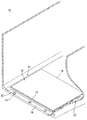
請求項5の発明は、劣化した構造物の入隅に用いられるハンチ部材であって、第1面およびそれに対向する第2面と、第1端および第2端とを有する本体、および本体の第2端側に第2面よりへこんだ窪み部を備え、第1面の長さが第2面の長さより長くなるように本体の第1端と直交する端面を第1面に対して傾斜させて形成した、ハンチ部材である。 The invention of claim 5 is a hunch member used in a corner of a deteriorated structure, the main body having a first surface and a second surface opposite to the first surface, and a first end and a second end, and The second end side is provided with a recessed portion that is recessed from the second surface, and the end surface orthogonal to the first end of the main body is inclined with respect to the first surface so that the length of the first surface is longer than the length of the second surface. This is a haunch member formed.
請求項5の発明では、窪み部を第2面よりへこませて本体の第2端側に形成することにより、請求項1の発明と同様に、ビスを隣接する本体で覆うことができ、ビスごとに止水処理が必要なくなる。しかも、ビスが本体の表面に現れない上、本体の表面を面一に揃えることができるため、本体上を水は滑らかに流れる。 In the invention of claim 5, by forming the indentation from the second surface on the second end side of the main body, the screw can be covered with the adjacent main body as in the invention of claim 1, No water stop treatment is required for each screw. Moreover, since the screws do not appear on the surface of the main body and the surface of the main body can be made flush, water flows smoothly on the main body.
また、第1面の長さが第2面の長さより長くなるように本体の第1端と直交する端面を第1面に対して傾斜させて形成する。これにより、ハンチ部材に窪み部などがあっても、たとえば、入隅を形成する2つの壁面上に設けた各更生パネルの表面にハンチ部材の傾斜端面を密着させることができる。このため、ハンチ部材と更生パネルとの間を止水処理することができる。 Further, the end surface orthogonal to the first end of the main body is inclined with respect to the first surface so that the length of the first surface is longer than the length of the second surface. Thereby, even if there exists a hollow part etc. in a haunch member, the inclined end surface of a haunch member can be closely_contact | adhered to the surface of each renovation panel provided on the two wall surfaces which form an entrance corner, for example. For this reason, a water stop process can be performed between the hunch member and the rehabilitation panel.
請求項6の発明は、入隅を有する劣化した構造物の壁面を更生する方法であって、(a)入隅を形成する2つの壁面にそれぞれ更生パネルを取り付けるステップ、(b)先行する請求項5のハンチ部材の傾斜する端面を更生パネルの表面に当てて、先行ハンチ部材の窪み部を貫通したビスで先行ハンチ部材を固定するステップ、(c)後続するハンチ部材の本体
の第1端側で先行ハンチ部材のビスを覆いながら、先行ハンチ部材の本体の第2端と第1端とを接合し、後続ハンチ部材の窪み部を貫通したビスで後続ハンチ部材を固定するステップ、(d)ステップ(c)および(d)を繰り返すステップ、および(e)劣化した構造物の壁面と更生パネルおよびハンチ部材との間に充填材を充填するステップを含む、劣化した構造物の壁面の更生方法である。
The invention of claim 6 is a method of rehabilitating a wall of a deteriorated structure having a corner, wherein (a) attaching a rehabilitation panel to each of two wall surfaces forming the corner, (b) preceding claim The step of applying the inclined end surface of the haunch member of item 5 to the surface of the rehabilitation panel and fixing the preceding haunch member with a screw penetrating the recessed portion of the preceding haunch member, (c) the first end of the main body of the succeeding haunch member Joining the second end and the first end of the body of the preceding haunch member while covering the screw of the preceding haunch member on the side, and fixing the succeeding haunch member with a screw penetrating the recess of the succeeding haunch member; (d A step of repeating steps (c) and (d), and (e) filling a wall of the deteriorated structure with a filler between the wall of the deteriorated structure and the rehabilitation panel and the hunch member. It is a method.
請求項6の発明では、請求項5の発明と同様の作用を示す。 The invention of claim 6 has the same effect as that of the invention of claim 5.
この発明によれば、受部の先端を傾斜させた更生パネル部材を用い、この更生パネル部材の受部を隣接する更生パネル部材の係合部に嵌めることにより、施工性に優れながら、劣化した構造物の湾曲部分の壁面を覆うことができる。 According to this invention, using the rehabilitation panel member in which the tip of the receiving portion is inclined, and fitting the receiving portion of the rehabilitation panel member to the engaging portion of the adjacent rehabilitation panel member, the workability is improved while being deteriorated. The wall surface of the curved portion of the structure can be covered.
この発明の上述の目的,その他の目的,特徴および利点は、図面を参照して行う以下の実施例の詳細な説明から一層明らかとなろう。 The above object, other objects, features and advantages of the present invention will become more apparent from the following detailed description of embodiments with reference to the drawings.
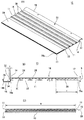
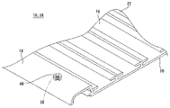
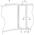
図1に示すこの発明の一実施例である更生パネル部材10は、たとえば、農業用あるいは下水用の開水路、下水暗渠、下水処理場の沈殿池あるいは貯水槽、上水施設の貯水池あるいは配水池、ビルピットまたは雨水貯留槽、ビル外壁、高速道路の遮音壁などの、構造物が劣化したときにその内壁、底面などを更生するために使用される。つまり、これらの劣化した構造物を取り壊すことなく、構造物の強度回復や表面補修を図るために、その壁面に取り付けられる。特に、この実施例の更生パネル部材10は、構造物の壁面であってかつ同じ面内で湾曲した壁面に用いられるので、以下、湾曲壁面用更生パネル部材と言う。
A
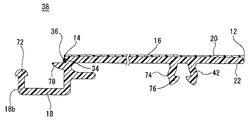
図1、図2(A)、図2(B)および図2(C)に示すように、湾曲壁面用更生パネル部材10は、第1端12と第2端14とを有する本体16を含み、隣り合う第1端12と第2端14とを接合して更生パネルを形成するものである。
As shown in FIGS. 1, 2 (A), 2 (B), and 2 (C), the curved wall
本体16は、矩形の板状で、平らな第1面20とそれに対向する第2面22とを有し、塩化ビニル樹脂やポリオレフィン樹脂などの合成樹脂で形成される。第1面20の表面はアクリル樹脂など耐候性を有する樹脂層24で覆われ、樹脂層24は2層押出成形により一体的に形成される。ポリオレフィン樹脂には、たとえばポリエチレンやポリプロピレンなどが用いられる。本体16の長さaは、湾曲壁面用更生パネル部材10が開水路の底面に取り付けられる場合に、その底面の幅より少し短めに設定される。本体16の幅bは適宜設定される。
The
本体16の第2端14に窪み部18、係合部32および切欠34が設けられ、本体16の第1端12側に受部28が設けられ、本体16の第2面22に突起部30が設けられる。これらは、塩化ビニル樹脂やポリオレフィン樹脂などの合成樹脂で形成され、本体16の長さ方向の全長に亘って設けられる。
A
窪み部18は、本体16の第2端14側に設けられ、第1端12と反対方向に突出する
。窪み部18の断面形状はJ字状であり、その近端側18aは本体16の第2端14と連結し、遠端側18bは本体16の第1面20側へ湾曲する。窪み部18の遠端側18bの先はくの字状に曲がり、その先に係り部25が形成される。係り部25は窪み部18の遠端側18bから本体16側へ突出する。
The
また、窪み部18は第2面22よりへこみ、窪み部18の最も低い位置にアンカ取付部として複数の貫通孔26が間隔を隔てて設けられる。貫通孔26の内径はたとえば、13mmであり、各貫通孔26のピッチは100〜150mmである。
Moreover, the
受部28は本体16の第1端12側の第2面22に設けられる。受部28は本体16に対してほぼ平行に設けられ、受部28の基端が本体16に結合することによって、受部28および本体16の第1端12側はコの字状の断面形状を形成する。
The receiving
そして、本体16の第1端12側と受部28との間に空間が形成され、この受部28による空間で隣接する係合部32を受ける。受部28による空間の間隔は、受部28の板の厚みと同じまたはそれより少し大きめに設定される。また、受部28の幅cは係合部32の幅dに比べて大きく設定される。たとえば、本体16の幅bが300mmで、本体16の長さaが1000mmの湾曲壁面用更生パネル部材10の場合、係合部32の幅dが90mmであるのに対して、受部28の幅cは10〜110mmに設定される。
A space is formed between the
突起部30は本体16の第2面22に設けられ、複数、この実施例では、4つの突起部30が間隔を隔てて並ぶ。突起部30の断面形状はT字状やトの字状である。
The
係合部32は、本体16の第2端14、つまり窪み部18の近端側18aに設けられ、本体16の第2端14側から窪み部18と同じ方向に、つまり第1端12と反対方向に突出する。係合部32の上面は第1面20より本体16の厚みの分だけ下がった位置に設けられ、本体の側端面に対して直角である。係合部32の下面は湾曲し、上面に対して傾斜して設けられる。このため、係合部32の断面形状は略三角形状に形成される。
The engaging
切欠34は係合部32のすぐ下に設けられる。その断面形状は略矩形であり、切欠34の上面は係合部32の下面を延長するように形成される。切欠34の中にエラストマなどの止水材36が嵌め込まれる。たとえば、止水材36の断面形状はのこぎり形状であり、のこぎりの歯のように凸凹が交互に並んでいる部分は切欠34の開口を向く。
The
このような湾曲壁面用更生パネル部材10は押出成形などにより作成され、本体16の長さaは湾曲壁面用更生パネル部材10を押し出す長さにより調整される。
The curved wall
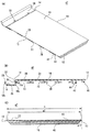
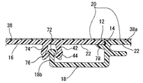
また、図3(A)、図3(B)および図3(C)に示す非湾曲壁面用更生パネル部材38は、劣化した構造物の、同じ面内では湾曲していない壁面(非湾曲壁面)に用いられる。なお、図1に示す湾曲壁面用更生パネル部材10と同様により共通する部分については同じ番号を付して説明を省略する。
Further, the non-curved wall
非湾曲壁面用更生パネル部材38は本体16を有し、本体16の第1端12側に受部40が設けられ、本体16の第2面22に係止部42および突起部30が設けられ、本体16の第2端14に窪み部18、係合部32および切欠34が設けられ、これらは本体の長さ方向の全長に亘って形成される。
The non-curved wall
受部40は本体16とともにコの字状の断面形状を形成し、本体16と受部40との間に空間が設けられる。この受部40による空間の幅e1は係合部32の幅dとほぼ同じまたはそれよりも多少大きくなるように、受部40の幅e2は係合部32の幅dよりも少し
大きく設定される。
The receiving
係止部42は、本体16の第2面22に設けられ、第2面22からほぼ直角に突出する。係止部42の先は、くの字状に曲がり、係止部42の先に係り部44が形成される。
The locking
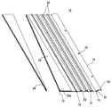
また、図4(A)、図4(B)および図4(C)に示す湾曲壁面用ハンチ部材45は、劣化した構造物の湾曲壁面を含む部分の入隅に用いられ、たとえば、後述する開水路の側面の更生パネルと底面の更生パネルとの間に取り付けられる。この湾曲壁面用ハンチ部材45は図1に示す湾曲壁面用更生パネル部材10とほぼ同じであるが、本体16の第1端12に直交する端面の角度が異なる。図2(C)に示すように湾曲壁面用更生パネル部材10では、第1端12に直交する端面11は第1面20に対して直角であるが、図4(C)に示すように湾曲壁面用ハンチ部材45では、第1面20の長さaが第2面22の長さa2より長くなるように、第1端12に直交する端面13は第1面20に対して角度θ1:45度で傾斜する。これ以外の部分に関しては図1実施例の示す湾曲壁面用更生パネル部材10と同様であるため、説明は省略する。
4A, FIG. 4B, and FIG. 4C are used at the corners of the portion including the curved wall surface of the deteriorated structure, and will be described later, for example. It is attached between the rehabilitation panel on the side of the open channel and the rehabilitation panel on the bottom. The curved wall
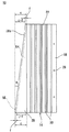
さらに、図5(A)、図5(B)および図5(C)に示す非湾曲壁面用ハンチ部材47は、劣化した構造物の非湾曲壁面を含む部分の入隅に用いられる。この非湾曲壁面用ハンチ部材47は図3(A)に示す非湾曲壁面用更生パネル部材38とほぼ同じであるが、図4(A)に示す湾曲壁面用ハンチ部材45と同様に、図5(C)に示すように非湾曲壁面用ハンチ部材47では本体16の第1端12に直交する端面13が第1面20に対して角度θ1:45度で傾斜する点が図3(C)に示す非湾曲壁面用更生パネル部材38の端面11と異なる。これ以外の部分に関しては図3(A)に示す非湾曲壁面用更生パネル部材38と同様であるため、説明は省略する。
Furthermore, the non-curved wall
このような湾曲壁面用更生パネル部材10または非湾曲壁面用更生パネル部材38などを用いて断面形状が矩形状の開水路を更生する場合、まず、開水路の施工部分より上流側にコンクリートパネルなどで水を予め堰き止めて、水中ポンプなどにより堰き止められた水を施工部分より下流側に放流する。そして、開水路の内面(底面および側面)の泥などを高圧洗浄機などで除去し、開水路の内面の特に突き出た部分をディスクサンダーなどで除去する。
When rehabilitating an open water channel having a rectangular cross-section using such a curved wall rehabilitated
次に、複数の図6(A)および図6(B)に示すスペーサ48を用意する。スペーサ48は、湾曲壁面用更生パネル部材10および非湾曲壁面用更生パネル部材38を開水路の内面に取り付けた際に、窪み部18と開水路の内面との間に介在し、これらの間に間隔を持たせるものである。この間隔は後述する充填材の流路として利用される。
Next, a plurality of
スペーサ48はゴムなどで形成されるが、その材質は限定されない。スペーサ48は円筒形状で、その内径は窪み部18の貫通孔26の内径と同じまたはそれより少し大きく設定される。スペーサ48の内径と外径との差は、たとえば10mmで、高さは5mmである。スペーサ48には切込み49が入れられ、図3(B)に示すように、切込み49は、たとえば角度θ2:90度で形成される。
The
図7に示すように、各スペーサ48を、貫通孔26の周りの第2面22側に両面テープなどで取り付ける。
As shown in FIG. 7, each
図8に示す開水路50の直線部分(非湾曲)の底面には非湾曲壁面用更生パネル部材38を用いる。本体16の第2面22を開水路50の底面側に向け、本体16の第1端12が開水路50の長手方向に対して直角になるようにして、非湾曲壁面用更生パネル部材38を開水路50の直線部分の底面に配置する。そして、アンカ52を貫通孔26およびス
ペーサ48の孔に挿入し、開水路50の底面に打ち込んで、非湾曲壁面用更生パネル部材38を固定する。
A renovated
なお、開水路50の底面が窪んでいて、窪み部18と開水路50の底面との間隔が広い場合には、スペーサ48(図6(A))の切込み49からスペーサ48をアンカ52に挿入して、スペーサ48を窪み部18と開水路50の底面との間に継ぎ足すことができる。このとき、スペーサ48に切込み49が入っているため、アンカ52を開水路50の底面に打ち込んだ後でもスペーサ48をアンカ52に簡単に取り付けることができる。
In addition, when the bottom surface of the
続いて、図9および図10に示すように、この先行して開水路50に固定された非湾曲壁面用更生パネル部材38aに後続する非湾曲壁面用更生パネル部材38を連結する。
Subsequently, as shown in FIGS. 9 and 10, the non-curved wall surface renovated
ここで、先行する非湾曲壁面用更生パネル部材38aを後続する非湾曲壁面用更生パネル部材38と区別するため、先行する非湾曲壁面用更生パネル部材を38aと示したが、非湾曲壁面用更生パネル部材38と同様のものである。
Here, in order to distinguish the preceding non-curved wall
すなわち、図11に示すように、非湾曲壁用更生パネル部材38を斜めに傾け、その本体16の第1端12を先行非湾曲壁用更生パネル部材38aの係合部32の上面に当て、受部40の内面を先行非湾曲壁用更生パネル部材38aの係合部32の下面に当接して、受部40を先行非湾曲壁用更生パネル部材38aの係合部32に嵌める。それから、矢印53に示すように本体16の傾きを小さくすると、受部40の内面は先行非湾曲壁用更生パネル部材38aの係合部32の湾曲した下面に沿いながら、受部40の先端は先行非湾曲壁用更生パネル部材38aの切欠34へ誘導される。これに伴い、係止部42は先行非湾曲壁用更生パネル部材38aの窪み部18の遠端側18bに当たるため、本体16の第1端12を支点として本体16を押し下げると、図12に示すように、係止部42は先行非湾曲壁用更生パネル部材38aの窪み部18の内側に入る。
That is, as shown in FIG. 11, the non-curved wall
このように、係合部32の下面を湾曲しながら斜めに切り取られるため、本体16の第1端12と垂直な方向の長さが長くても、受部40を先行非湾曲壁用更生パネル部材38aの係合部32に嵌めることができる。また、本体16の第1端12を支点として本体16を押し下げることにより、本体16の第1端12側の長さが長くても、てこの原理を利用して小さな力で係止部42を先行非湾曲壁用更生パネル部材38aの窪み部18内に挿入するができる。このため、開水路50の内面に対する非湾曲壁用更生パネル部材38を連結する際の負担は小さくてすみ、しかも人の手でも簡単に非湾曲壁用更生パネル部材38を連結することができ、作業性に優れる。
Thus, since the lower surface of the engaging
そして、受部40は本体16の第1端12側と協働して先行非湾曲壁用更生パネル部材38aの係合部32を受ける。これにより、本体16の第1端12側が先行非湾曲壁用更生パネル部材38aの本体16の第2端14側から上下方向へ動くのが防止される。また、係止部42が先行非湾曲壁用更生パネル部材38aの窪み部18の遠端側18bに当接して、非湾曲壁用更生パネル部材38が横方向に滑るのが防止される。さらに、係止部42の係り部44が先行非湾曲壁用更生パネル部材38aの係り部25と互いに係わり合うことにより、非湾曲壁用更生パネル部材38が上方へ外れてしまうのが防がれる。
The receiving
なお、係止部42の係り部44と先行非湾曲壁用更生パネル部材38aの係り部25との間に隙間55aがあり、かつ係合部32の下面が湾曲する。このため、図13に示すように、本体16は先行非湾曲壁用更生パネル部材38aとの接合状態を維持したまま先行非湾曲壁用更生パネル部材38aに対する第1面20の角度θ3が180度より小さくなる方向へ曲げることができる。
There is a
これと反対に、本体16の第2面22と先行非湾曲壁用更生パネル部材38aの窪み部18の遠端側18bの先との間に隙間55bがあり、本体16は合成樹脂で形成されるため、図14に示すように本体16は、先行非湾曲壁用更生パネル部材38aの係合部32を支点として撓み、先行非湾曲壁用更生パネル部材38aに対する第1面20の角度θ3が180度より大きくなる方向へ曲がる。
On the contrary, there is a
このように、隣り合う非湾曲壁用更生パネル部材38、38aどうしの接合状態を維持したままこれらの連結角度が可変するため、更生パネル50を開水路50の底面の凹凸などにある程度合わせることができる。
As described above, since the connecting angle of the rehabilitating
また、図12に示すように、受部40の先端は先行非湾曲壁用更生パネル部材38aの切欠34内に挿入されるため、切欠34内の止水材36により本体16の第1端12と先行非湾曲壁用更生パネル部材38aの本体16の第2端14との接合部が止水される。
Further, as shown in FIG. 12, the front end of the receiving
さらに、本体16の第1端12側で先行非湾曲壁用更生パネル部材38aの窪み部18を覆いながら、本体16の第1端12を先行非湾曲壁用更生パネル部材38aの本体16の第2端14と接合し、しかも、本体16の第1面20から係合部32の上面までの長さが本体16の厚みと一致する。このため、本体16の第1端12側を係合部32に載せるだけで、非湾曲壁用更生パネル部材38の高さが調整されて、本体16の第1面20は隣接する本体16の第1面20と面一になり揃う。
Further, the
次に、開水路50の直線部分の底面に続く湾曲部分の底面に湾曲壁面用更生パネル部材10を取り付ける。この場合、図15に示すように、まず、図1に示す湾曲壁面用更生パネル部材10の受部28および本体16の第1端12側を切断する。このとき、図15〜図17に示すように、受部28の先端28aおよび本体16の第1端12が第2端14に対して傾斜し、第2端14に対する先端28aおよび第1端12の傾斜角度が、図9に示す開水路50の湾曲部分の湾曲角度αになるようにする。なお、切断後に残る受部28の最短幅fが、係合部32の幅dとより長くなるようにする。
Next, the curved wall
そして、図15に示す切断して切り離された三角形状の受部28の切れ端54を裏返して、受部28による空間の中に挿入して、切れ端54で受部28による空間を埋める。このとき、図17に示すように、切れ端54の最長辺を受部28の最長辺に合わせると、受部28の最長幅cに対して切れ端54の最長幅は(c−f)となるため、埋められた切れ端54の先端から受部28の先端28aまでの間に幅fの空間56が形成される。この幅fは係合部32の幅dよりも長いため、この空間56に係合部32を嵌めることができる。
Then, the
また、図18に示すように、開水路50に固定された非湾曲壁面用更生パネル部材38の窪み部18の遠端側18bを切断する。このとき、本体16の第1面20から切断された窪み部18の端までの高さgは、図2(B)に示す第1面20から受部28の下面までの高さhと同じまたはそれより大きくなるように設定される。
Moreover, as shown in FIG. 18, the
そして、図19に示すように、湾曲壁面用更生パネル部材10の受部28による空間内に開水路50に固定された非湾曲壁面用更生パネル部材38の係合部32を嵌め、受部28の下面を非湾曲壁面用更生パネル部材38の窪み部18の端に当てる。これにより、本体16の第1端12側は非湾曲壁面用更生パネル部材38の窪み部18を覆い、しかも第1端12は非湾曲壁面用更生パネル部材38の第2端14と接合するため、隣り合う湾曲壁面用更生パネル部材10の表面と非湾曲壁面用更生パネル部材38の表面とを面一に揃えながら、これらを連結することができる。また、図20に示すように、湾曲壁面用更生パネル部材10が開水路50の湾曲壁面部分に沿って、非湾曲壁面用更生パネル部材38
に連結される。
And as shown in FIG. 19, the engaging
Connected to
そして、貫通孔26にアンカ52を挿入し、開水路50の底面に打ち込んで、湾曲壁面用更生パネル部材10を固定する。
Then, the
なお、図19において、湾曲壁面用更生部材10と非湾曲壁面用更生パネル部材38との連結状態をわかり易くするため、連結したこれらの第2面22側を示している。このため、アンカ52などを省略している。
In FIG. 19, the connected
次の後続する湾曲壁面用更生パネル部材10aを連結する場合も、先の湾曲壁面用更生パネル部材10とほぼ同様にする。なお、後続する湾曲壁面用更生パネル部材10aを先行する湾曲壁面用更生パネル部材10と区別するため、後続湾曲壁面用更生パネル部材を10aと示したが、湾曲壁面用更生パネル部材10と同様のものである。
Even when the subsequent succeeding curved wall wall
すなわち、後続湾曲壁面用更生パネル部材10aの先端28aの傾斜角度が、図20に示す開水路50の湾曲壁面部分の湾曲角度βになるように、受部28を切断して、受部28の切れ端54を受部28による空間内に挿入する。
That is, the receiving
また、図18の非湾曲壁面用更生パネル部材38と同様に、開水路50に固定された湾曲壁面用更生パネル部材10の窪み部18の遠端側18bを切断し、窪み部18の端の高さを後続湾曲壁面用更生パネル部材10aの第1面20から受部28の下面までの高さhと同じまたはそれより大きくする。
Further, similarly to the non-curved wall
それから、後続湾曲壁面用更生パネル部材10aの受部28による空間に開水路50に固定された湾曲壁面用更生パネル部材10の係合部32を嵌めて、後続湾曲壁面用更生パネル部材10aの受部28の下面を湾曲壁面用更生パネル部材10の窪み部18の遠端に当てる。なお、窪み部18の遠端が受部28の下面の高さより低いと、後続湾曲壁面用更生パネル部材10aの受部28の下面が窪み部18の遠端に当たらない場合もある。
Then, the engaging
このように、開水路50の底面形状に合わせて、非湾曲壁面用更生パネル部材38または湾曲壁面用更生パネル部材10を選択し、湾曲壁面用更生パネル部材10の先端28aの傾斜角度を調整して、非湾曲壁面用更生パネル部材38または湾曲壁面用更生パネル部材10の連結作業を繰り返すことにより、開水路50の底面形状に沿った更生パネル58が形成される。
Thus, according to the bottom shape of the
次に、図21に示すように開水路50の側面にも、底面の直線部分と同様に、複数の非湾曲壁面用更生パネル部材38を取り付け、これらを連結して、開水路50の側面の更生パネル60を形成する。
Next, a plurality of non-curved wall
それから、開水路50の直線部分では底面の更生パネル58と側面の更生パネル60との間に板状体61を介して非湾曲壁面用ハンチ部材47を配する。板状体61は止水性を有する発泡ゴムなどで形成される。板状体61の断面の高さは、たとえば10〜15mmで、幅は25〜40mmであり、幅はハンチ部材の本体の厚みより大きく形成される。
Then, the non-curved wall
図22に示すように、板状体61を底面の更生パネル58および側面の更生パネル60のそれぞれの表面上に配置し、各板状体61上に非湾曲壁面用ハンチ部材47の両端面13のそれぞれを押し当てて、非湾曲壁面用ハンチ部材47と更生パネル58、60との間に板状体61を挟む。そして、そのままの状態で、非湾曲壁面用ハンチ部材47の窪み部18から更生パネル58、60の本体16へビス63を打ち込んで、更生パネル58、60に非湾曲壁面用ハンチ部材47を固定する。それから、図23に示すように、非湾曲壁
面用ハンチ部材47の本体16の第1面20側からはみ出ている板状体61をカッタなどで切断する。
As shown in FIG. 22, the plate-
そして、図12に示す非湾曲壁面用更生パネル部材38と同様に、受部40による空間に先行非湾曲壁面用ハンチ部材47の係合部32を嵌めてから、本体16を押し下げる。押し下げたことで、受部40の先端40bは、先行非湾曲壁面用ハンチ部材47の切欠34内に嵌まり、止水材36を潰して接合部を止水する。また、係止部42が先行非湾曲壁面用ハンチ部材47の窪み部18の内側に入り、係り部44が先行非湾曲壁面用ハンチ部材47の係り部25に係止されることにより、非湾曲壁面用ハンチ部材47の上下方向および水平方向の動きが制限されて、非湾曲壁面用ハンチ部材47どうしが連結される。さらに、先行非湾曲壁面用ハンチ部材47の窪み部18が本体16で覆われて、非湾曲壁面用ハンチ部材47の第1面20は面一に揃う。そして、これを繰り返して、底面の更生パネル58と側面の更生パネル60との間を非湾曲壁面用ハンチ部材47で覆う。
Then, similarly to the non-curved wall surface
また、開水路50の湾曲部分では、湾曲壁面用ハンチ部材45を用いる。まず、図15〜図17に示す湾曲壁面用更生パネル部材10と同様に、第1端12および先端28aの第2端14に対する傾斜角度が開水路50の湾曲部分の湾曲角度αになるように、本体16の第1端12側および受部28を切断して、受部28の切れ端54を受部28による空間の中に挿入する。また、図18と同様に、先行する湾曲壁面用ハンチ部材45または非湾曲壁面用ハンチ部材47の窪み部18の遠端側18bを切断する。
Further, a curved wall
そして、図22および図23に示す非湾曲壁面用ハンチ部材47と同様に、湾曲壁面用ハンチ部材45の傾斜する端面13と更生パネル58、60との間に板状体61を挟んで、湾曲壁面用ハンチ部材45の窪み部18から更生パネル58、60の本体16へビス63を打ち込む。湾曲壁面用ハンチ部材45の本体16の第1面20からはみ出ている板状体61をカッタなどで切断する。
Then, similarly to the non-curved wall
それから、図19と同様に、受部28による空間内に先行ハンチ部材45、47の係合部32を嵌めて、本体16の第1端12側で先行ハンチ部材45、47の窪み部18を覆う。図22と同様に、窪み部18から本体16にビス63を打ち込んで、板状体61を介して湾曲壁面用ハンチ部材45を更生パネル58、60にそれぞれ固定する。湾曲壁面用ハンチ部材45の連結作業を繰り返すことによって、開水路50の底面形状に沿って、底面の更生パネル58と側面の更生パネル60との間を湾曲壁面用ハンチ部材45で覆うことができる。
Then, similarly to FIG. 19, the engaging
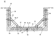
最後に、図24に示すように開水路50の側面と側面の更生パネル60との間からモルタルなどの充填材64を注入すると、充填材64は開水路50の側面と本体16との間、スペーサ48により形成された開水路50の側面と窪み部18との間、および窪み部18の中を通り、開水路50の底面と更生パネル58との間に流れ、開水路50の内面と各更生パネル58、60との間に充填材64が充填される。このとき、本体16の突起部30が充填材64に嵌まり、投錨効果を示す。よって、既設の開水路50および各更生パネル58、60は充填材64により一体化する。なお、充填材64は受部28による空間の中に侵入しないが、この空間の中には切れ端54が嵌められているため、この部分の強度は切れ端54により補強されるとともに、非破壊検査の妨げとなる空洞部が形成されない。
Finally, as shown in FIG. 24, when a
このように、本体16の第1端12側で窪み部18に取り付けられたアンカ52を覆い、かつ受部28、40と切欠34内の止水材36とにより隣り合う第1端12と第2端14との接合部を止水する。これにより、開水路50内を流れる水は窪み部18からアンカ52を介して更生パネル50と開水路50の内面との間に侵入せず、更生された開水路50の耐久性は維持される。その上、更生パネル50を形成した後に本体16の接合部だけ
でなく、アンカ52の1つ1つにシリコンシーラントなどで止水処理する必要がなくなり、施工性が向上する。
In this way, the
また、隣り合う本体16の第1面20は面一になり、またアンカ52の頭部などが第1面20に現れないため、外観的に優れ、しかも、水は開水路50の中をスムーズに流れて、流速や流量が確保される。
Further, the
さらに、本体16および窪み部18を塩化ビニル樹脂で形成することにより、湾曲壁面用更生パネル部材10および非湾曲壁用更生パネル部材38の低コスト化が図られる。また、本体16の第1面20の表面をアクリル樹脂層24で覆うことにより、塩化ビニル樹脂の紫外線による劣化が防止され、更生された開水路50の耐久性を確保することができる。
Further, by forming the
この本体16の第2面22に突起部30を設けることにより、本体16の剛性を高められ、本体16の厚みを薄くすることができる。これにより、湾曲壁面用更生パネル部材10および非湾曲壁用更生パネル部材38の材料コストが抑えられ、しかも湾曲壁面用更生パネル部材10および非湾曲壁用更生パネル部材38が軽くなるため、作業性に優れる。
By providing the
また、第1端12および受部28の先端28aの傾斜角度を開水路50の湾曲部分の湾曲角度に合わせ、本体16および受部28を切断することにより、湾曲用更生パネル部材10は更生パネル部材10、38に対して傾斜して連結され、本体16が湾曲部分の湾曲の底面形状に沿って屈曲した更生パネル58が形成される。このため、更生パネル58は開水路50の湾曲部分の底面を覆うことができることにより、開水路50を流れる水が更生パネル58と開水路50の底面との間に浸入しにくいため、更生された開水路50の強度は維持される。
Further, by adjusting the inclination angle of the
そして、受部28の幅を係合部32の幅より長く形成しておくことにより、受部28の先端を一定範囲で所望する湾曲角度に切断しても、受部28の幅を係合部32の幅より長く残すことができるため、受部28を隣接する係合部32に嵌めることができる。これにより、受部28は係合部32により係止されるため、湾曲壁面用更生パネル部材10を非湾曲壁面用更生パネル部材38または湾曲壁面用更生パネル部材10に簡単に接合することができる。
Then, by forming the width of the receiving
なお、開水路50の内面と各更生パネル58、60との間に鉄筋を配してもよい。ここに鉄筋を入れると、開水路50、鉄筋および更生パネル58、60が充填材64により一体化されて、これらの引張強度が向上し、更生された開水路50の耐久性がさらに向上する。
In addition, you may arrange | position a reinforcing bar between the inner surface of the
また、突起部30の間または突起部30自体に金属製の補強部材などを取り付けてもよい。これにより、本体16の剛性を向上することができる。
Further, a metal reinforcing member or the like may be attached between the
さらに、図22では、湾曲壁面用ハンチ部材45および非湾曲壁面用ハンチ部材47の窪み部18のビス63を打ち込んで、開水路50の更生パネル58、60にハンチ部材45、47を固定した。これに対して、図25に示すように、ハンチ部材45、47の窪み部18を開水路50の底面および側面に取り付けた更生パネル部材10、38の窪み部18に合わせて、ハンチ部材45、47の窪み部18から更生パネル部材10、38の窪み部18にビス53を打ち込んで、開水路50の更生パネル58、60にハンチ部材45、47を固定することもできる。
Further, in FIG. 22, the
また、ハンチ部材45、47の窪み部18から更生パネル58、60にビス63を打ち
込んで、ハンチ部材45、47を固定したが、ハンチ部材45、47の窪み部18の貫通孔26から開水路50のハンチ部へアンカを挿入して、ハンチ部材45、47を固定することもできる。
Further, the
そして、この湾曲壁面用ハンチ部材45および非湾曲壁面用ハンチ部材47と更生パネル58、60との間を発泡ゴムなどの板状体61により止水したが、ハンチ部材45、47と更生パネル58、60との間との間にシリコンシーラントのようなコーキング処理により止水処理することもできる。
Then, the curved wall
また、突起部30を一方向に延びるように設けたが、突起部を格子状に設けることもできる。図26(A)および図26(B)に示すように、一方の突起部66は本体16の第1端12および第2端14に平行に延び、他方の突起部68は本体16の第1端12および第2端14に垂直に延びる。このとき、一方の突起部66の高さと他方の突起部68の高さを同じにしてもよいが、一方の突起部66の高さを他方の突起部68の高さより低くすることにより、充填材64の流動性を向上させることもできる。また、突起部66、68の断面形状を直線状にしてもよいし、上記と同様にT字状やト字状に形成してもよい。このように、本体16の第2面22に突起部66、68を形成することにより、本体16の第1端12および第2端14に垂直な方向だけでなく、それに平行な方向に対しても、本体16の剛性が高まる。なお、突起部66、68は湾曲壁面用更生パネル部材10および非湾曲壁用更生パネル部材38のどちらに対しても適用される。
Moreover, although the
そして、図27(A)および図27(B)に示すように、この格子状の突起部66および突起部68の少なくともいずれか一方に貫通孔70を設けることができる。貫通孔70は突起部66、68の長手方向に対して垂直に設けられる。この貫通孔70を設けることにより、充填材64がこの貫通孔70を通り、更生パネル58、60と開水路50の内面との間に満遍なく充填させることができる。
Then, as shown in FIGS. 27A and 27B, a through-
さらに、図3に示すように係合部32を窪み部18の近端側18aに設け、受部40を係止部42より第1端12側に形成したが、図28に示すように係合部72を窪み部18の遠端側18bに設け、受部74を係止部42より第2端14側に形成することもできる。この係合部72は窪み部18の遠端側18bを拡径した部分である。受部74は係止部42を線対称にした形状であり、本体16からほぼ直角に突出して、その先のくの字状に曲がる。曲がった係り部76は受部74から本体16の第1端12側に突出する。本体16の第2端14に切欠34が形成され、その中に止水材36が設けられる。切欠34の下側で、本体16の第1面20から本体16の厚みの分だけ下がった位置に台座部78が形成される。台座部78は本体16の第2端14から窪み部18と同じ方向に突出し、その上面は第2端14の端面に対して直角である。
Further, as shown in FIG. 3, the engaging
そして、図29に示すように、非湾曲壁用更生パネル部材38の第1端12側を先行非湾曲壁用更生パネル部材38aの台座部78に載せて、受部74と係止部42との間に先行非湾曲壁用更生パネル部材38aの係合部72を嵌めると、受部74の係り部76は係止部42の係り部44と協働して係合部72を受ける。これにより、非湾曲壁用更生パネル部材38を先行非湾曲壁用更生パネル部材38aに接合して固定され、これらの第1面20を面一に揃う。ただし、本体16の第2面22と先行非湾曲壁用更生パネル部材38aの係合部72との間に隙間があるため、非湾曲壁用更生パネル部材38と先行非湾曲壁用更生パネル部材38aとの接合角度を変えることができる。
29, the
また、係止部42より第2端14側に設けた受部74だけでなく、図3に示す受部40を本体16の第1端12側にさらに形成してもよい。この場合、受部74が先行非湾曲壁用更生パネル部材38aの係合部72を受け、かつ受部40が先行非湾曲壁用更生パネル
部材38aの台座部78を受ける。
3 may be further formed on the
さらに、施工現場などで開水路50の湾曲部分の湾曲角度に合わせて、図15に示すように、受部28および本体16を切断したが、工場などで受部28の先端28aおよび第1端12を予め傾斜させた湾曲壁面用更生パネル部材10を製造しておき、これを施工現場に搬入して用いることもできる。この場合、受部28の先端28aおよび第1端12の傾斜角度が異なる数種類の湾曲用更生パネル部材10を用意しておき、これらを組み合わせることにより、多様な形状の開水路50の湾曲壁面部分の底面に対応することができる。
Furthermore, the receiving
また、開水路50の湾曲壁面部分に配置される更生パネル部材の全てに湾曲壁面用更生パネル部材10を用い、各湾曲壁面用更生パネル部材10において受部28の先端28aおよび第1端12の傾斜角度を開水路50の湾曲部分の湾曲角度に合わせて、受部28および本体16を切断した。これに対して、図30に示すように、開水路50の湾曲壁面部分に配置される更生パネル部材の内の1つに湾曲壁面用更生パネル部材10を用いて、この先端28aおよび第1端12の傾斜角度γを開水路50の湾曲部分の湾曲角度αより大きくなるように受部28を切断し、この湾曲壁面用更生パネル部材10に非湾曲壁面用更生パネル部材38を連結することもできる。
Further, the rehabilitated panel member for
そして、湾曲壁面用更生パネル部材10の受部28および本体16を切断したが、これらを切断せず、湾曲壁面用更生パネル部材10を非湾曲壁面用更生パネル部材38と同様に矩形状のまま用いることもできる。
And although the receiving
また、受部28の切れ端54で受部28による空間を埋めたが、スポンジやゴムなどで受部28による空間を埋めることもできる。
Moreover, although the space by the receiving
さらに、断面形状が矩形状の開水路50の側面には非湾曲壁面用更生パネル部材38を用いたが、断面形状が台形状の開水路50における湾曲部分の湾曲状側面には、断面形状が矩形状の開水路50の湾曲壁面部分の底面と同様に、湾曲壁面用更生パネル部材10を用いることもできる。
Furthermore, the non-curved wall
いずれにしても、この発明の各実施例の湾曲壁面用更生パネル部材10は、同じ面内で湾曲しあるいは曲がった壁面を補強する場合など、先行する更生パネル部材に対してその面内で角度を持たせて後続する更生パネル部材を固定する場合に、その後続更生パネル部材として利用できる。
In any case, the curved wall
また、上記実施例では、開水路50の直線部分に続く湾曲部分の底面において、非湾曲壁用更生パネル部材38の係合部32に湾曲壁面用更生パネル部材10の受部28を取り付けた。これと反対に、開水路50の湾曲部分の底面に続く直線部分の底面においては、湾曲壁面用更生パネル部材10の係合部32に非湾曲壁用更生パネル部材38の受部40を取り付ける。
Moreover, in the said Example, the receiving
なお、上で挙げた角度や寸法の具体的数値はいずれも単なる一例であり、必要に応じて適宜変更可能である。 It should be noted that the specific numerical values of the angles and dimensions given above are merely examples, and can be appropriately changed as necessary.
10、10a…湾曲壁面用更生パネル部材
12…第1端
14…第2端
13…端面
16…本体
18…窪み部
20…第1面
22…第2面
24…樹脂層
26…貫通孔
28、40…受部
32…係合部
38,38a…非湾曲壁面用更生パネル部材
45…湾曲壁面用ハンチ部材
47…非湾曲壁面用ハンチ部材
50…開水路
52…アンカ
58、60…更生パネル
63…ビス
64…充填材
DESCRIPTION OF
この発明は、ハンチ部材および劣化した構造物の壁面の更生方法に関し、特にたとえば、劣化した構造物を取り壊すことなく、構造物の強度回復や表面補修を図る、ハンチ部材および劣化した構造物の壁面の更生方法に関する。 This invention relates to retreading method of wall surface Ha inch member and degraded structures, in particular for example, without tear down structures deteriorated, promote strength recovery and surface repair of the structure, iii inch member and degraded structure It is related with the rehabilitation method of the wall.
それゆえに、この発明の主たる目的は、耐久性を維持しつつ、施工性に優れる、ハンチ部材および劣化した構造物の壁面の更生方法を提供することである。 Another object of the present invention, while maintaining durability, excellent workability, and to provide a retread process wall Ha inch member and degraded structure.
また、別の発明の主たる目的は、劣化した構造物の湾曲部分の壁面を覆うことができ、しかも施工性に優れる、ハンチ部材および劣化した構造物の壁面の更生方法を提供することである。 Further, an object of another aspect of the present invention, it is possible to cover a wall surface of the curved portion of the degraded structures, yet excellent workability, it is to provide a rehabilitation method for wall Ha inch member and degraded structure .
請求項1の発明は、劣化した構造物の入隅に用いられるハンチ部材であって、第1面およびそれに対向する第2面と、第1端および第2端とを有する本体、および本体の第2端側に第2面よりへこんだ窪み部を備え、第1面の長さが第2面の長さより長くなるように本体の第1端と直交する端面を第1面に対して傾斜させて形成した、ハンチ部材である。 The invention of claim 1 is a hunch member used in a corner of a deteriorated structure, and a main body having a first surface and a second surface opposite to the first surface, and a first end and a second end, and The second end side is provided with a recessed portion that is recessed from the second surface, and the end surface orthogonal to the first end of the main body is inclined with respect to the first surface so that the length of the first surface is longer than the length of the second surface. This is a haunch member formed.
請求項1の発明では、窪み部を第2面よりへこませて本体の第2端側に形成することにより、請求項1の発明と同様に、ビスを隣接する本体で覆うことができ、ビスごとに止水処理が必要なくなる。しかも、ビスが本体の表面に現れない上、本体の表面を面一に揃えることができるため、本体上を水は滑らかに流れる。 In the invention of claim 1 , by forming the indentation from the second surface on the second end side of the main body, the screw can be covered with the adjacent main body as in the invention of claim 1, No water stop treatment is required for each screw. Moreover, since the screws do not appear on the surface of the main body and the surface of the main body can be made flush, water flows smoothly on the main body.
請求項2の発明は、入隅を有する劣化した構造物の壁面を更生する方法であって、(a)入隅を形成する2つの壁面にそれぞれ更生パネルを取り付けるステップ、(b)先行する請求項5のハンチ部材の傾斜する端面を更生パネルの表面に当てて、先行ハンチ部材の窪み部を貫通したビスで先行ハンチ部材を固定するステップ、(c)後続するハンチ部材の本体
の第1端側で先行ハンチ部材のビスを覆いながら、先行ハンチ部材の本体の第2端と第1端とを接合し、後続ハンチ部材の窪み部を貫通したビスで後続ハンチ部材を固定するステップ、(d)ステップ(c)および(d)を繰り返すステップ、および(e)劣化した構造物の壁面と更生パネルおよびハンチ部材との間に充填材を充填するステップを含む、劣化した構造物の壁面の更生方法である。
The invention of
請求項2の発明では、請求項1の発明と同様の作用を示す。
The invention of
Claims (6)
第1端および第2端と、第1面およびそれに対向する第2面とを有する本体、
前記本体の第2端に突出して形成される係合部、および
前記本体の第1端側に形成されて、隣接する前記係合部を受ける受部を備え、
前記受部の先端および前記本体の第1端を前記本体の第2端に対して傾斜させて形成した、更生パネル部材。 A rehabilitation panel member for rehabilitating the wall of a deteriorated structure,
A body having a first end and a second end; a first surface and a second surface opposite thereto;
An engaging portion that protrudes from the second end of the main body, and a receiving portion that is formed on the first end side of the main body and receives the adjacent engaging portion;
A rehabilitation panel member formed by inclining the front end of the receiving portion and the first end of the main body with respect to the second end of the main body.
第1端および第2端と、第1面およびそれに対向する第2面とを有する本体、
前記本体の第2端に突出して形成される係合部、および
前記本体の第1端側に形成されて、隣接する前記係合部を受ける受部を備え、
前記受部の幅を前記係合部の幅より大きくしておき、前記受部の先端および前記本体の第1端を前記本体の第2端に対して傾斜させて切断できるようにした、更生パネル部材。 A rehabilitation panel member for rehabilitating the wall of a deteriorated structure,
A body having a first end and a second end; a first surface and a second surface opposite thereto;
An engaging portion that protrudes from the second end of the main body, and a receiving portion that is formed on the first end side of the main body and receives the adjacent engaging portion;
The width of the receiving portion is made larger than the width of the engaging portion, and the tip of the receiving portion and the first end of the main body are inclined with respect to the second end of the main body and can be cut. Panel member.
前記窪み部に形成されたアンカ取付部をさらに備え、
前記係合部を前記窪み部に形成し、
前記アンカ取付部に取り付けられたアンカを、隣接する前記本体の第1端側で覆い、かつ隣り合う前記第1端と前記第2端とを接合して、更生パネルを形成するようにした、請求項1または2記載の更生パネル部材。 A hollow portion recessed from the second surface on the second end side of the main body; and an anchor mounting portion formed in the hollow portion;
Forming the engaging portion in the recess,
The anchor attached to the anchor attachment portion is covered with the first end side of the adjacent main body, and the adjacent first end and the second end are joined to form a rehabilitation panel. The rehabilitation panel member according to claim 1 or 2.
(a)先行するかつ本体と、前記本体の第2端に突出して形成される係合部と、前記本体の第1端側に形成されて隣接する前記係合部を受ける受部とを含む更生パネル部材を前記劣化した構造物の壁面と間隔を隔ててアンカで固定するステップ、
(b)後続する請求項2の更生パネル部材の前記受部の先端および前記本体の第1端を前記本体の第2端に対して傾斜させて切断するステップ、
(c)前記先行更生パネル部材の前記係合部を前記後続更生パネル部材の前記受部で受けて、前記後続更生パネル部材を前記劣化した構造物の壁面と間隔を隔ててアンカで固定するステップ、
(d)前記劣化した構造物の壁面と前記更生パネル部材との間に充填材を充填するステップを含む、劣化した構造物の壁面の更生方法。 A method of rehabilitating the walls of a deteriorated structure,
(A) including a preceding main body, an engaging portion formed to protrude from the second end of the main body, and a receiving portion for receiving the adjacent engaging portion formed on the first end side of the main body. Fixing the rehabilitation panel member with an anchor spaced from the wall of the deteriorated structure;
(B) a step of cutting the distal end of the receiving portion and the first end of the main body of the renovated panel member according to claim 2 inclined with respect to the second end of the main body;
(C) receiving the engagement portion of the preceding rehabilitation panel member at the receiving portion of the subsequent rehabilitation panel member, and fixing the subsequent rehabilitation panel member with an anchor at a distance from the wall surface of the deteriorated structure; ,
(D) A method for rehabilitating a wall surface of a deteriorated structure, comprising a step of filling a filler between the wall surface of the deteriorated structure and the rehabilitation panel member.
第1面およびそれに対向する第2面と、第1端および第2端とを有する本体、および
前記本体の第2端側に前記第2面よりへこんだ窪み部を備え、
前記第1面の長さが前記第2面の長さより長くなるように前記本体の第1端と直交する端面を前記第1面に対して傾斜させて形成した、ハンチ部材。 A haunch member used in a corner of a deteriorated structure,
A main body having a first surface and a second surface opposite to the first surface, and a first end and a second end; and a recessed portion recessed from the second surface on the second end side of the main body,
A haunch member formed by inclining an end surface perpendicular to the first end of the main body with respect to the first surface so that the length of the first surface is longer than the length of the second surface.
(a)入隅を形成する2つの壁面にそれぞれ更生パネルを取り付けるステップ、
(b)先行する請求項5のハンチ部材の傾斜する端面を前記更生パネルの表面に当てて、前記先行ハンチ部材の窪み部を貫通したビスで前記先行ハンチ部材を固定するステップ、
(c)後続するハンチ部材の本体の第1端側で前記先行ハンチ部材の前記ビスを覆いながら、前記先行ハンチ部材の本体の第2端と前記第1端とを接合し、前記後続ハンチ部材の窪み部を貫通したビスで前記後続ハンチ部材を固定するステップ、
(d)前記ステップ(b)および(c)を繰り返すステップ、および
(e)前記劣化した構造物の壁面と前記更生パネルおよび前記ハンチ部材との間に充填材を充填するステップを含む、劣化した構造物の壁面の更生方法。 A method of rehabilitating a wall of a deteriorated structure having a corner,
(A) attaching a rehabilitation panel to each of the two wall surfaces forming the corner;
(B) applying the inclined end surface of the hunting member of the preceding claim 5 to the surface of the rehabilitation panel and fixing the preceding hunting member with a screw penetrating the recessed portion of the preceding hunting member;
(C) joining the second end and the first end of the main body of the preceding haunch member while covering the screw of the preceding haunch member on the first end side of the main body of the subsequent haunch member; Fixing the succeeding haunch member with a screw penetrating the recess of
(D) repeating the steps (b) and (c); and (e) filling with a filler between the wall of the deteriorated structure and the renovated panel and the haunch member. Rehabilitation method for the walls of structures.
Priority Applications (1)
| Application Number | Priority Date | Filing Date | Title |
|---|---|---|---|
| JP2012099497A JP5389976B2 (en) | 2005-03-24 | 2012-04-25 | Method for rehabilitating the wall of a haunch member and a deteriorated structure |
Applications Claiming Priority (3)
| Application Number | Priority Date | Filing Date | Title |
|---|---|---|---|
| JP2005085656 | 2005-03-24 | ||
| JP2005085656 | 2005-03-24 | ||
| JP2012099497A JP5389976B2 (en) | 2005-03-24 | 2012-04-25 | Method for rehabilitating the wall of a haunch member and a deteriorated structure |
Related Parent Applications (1)
| Application Number | Title | Priority Date | Filing Date |
|---|---|---|---|
| JP2010061908A Division JP5197662B2 (en) | 2005-03-24 | 2010-03-18 | Rehabilitation panel member and method for rehabilitation of wall of deteriorated structure |
Publications (2)
| Publication Number | Publication Date |
|---|---|
| JP2012197668A true JP2012197668A (en) | 2012-10-18 |
| JP5389976B2 JP5389976B2 (en) | 2014-01-15 |
Family
ID=42576982
Family Applications (2)
| Application Number | Title | Priority Date | Filing Date |
|---|---|---|---|
| JP2010061908A Expired - Fee Related JP5197662B2 (en) | 2005-03-24 | 2010-03-18 | Rehabilitation panel member and method for rehabilitation of wall of deteriorated structure |
| JP2012099497A Expired - Fee Related JP5389976B2 (en) | 2005-03-24 | 2012-04-25 | Method for rehabilitating the wall of a haunch member and a deteriorated structure |
Family Applications Before (1)
| Application Number | Title | Priority Date | Filing Date |
|---|---|---|---|
| JP2010061908A Expired - Fee Related JP5197662B2 (en) | 2005-03-24 | 2010-03-18 | Rehabilitation panel member and method for rehabilitation of wall of deteriorated structure |
Country Status (1)
| Country | Link |
|---|---|
| JP (2) | JP5197662B2 (en) |
Citations (5)
| Publication number | Priority date | Publication date | Assignee | Title |
|---|---|---|---|---|
| JPH03247809A (en) * | 1990-02-26 | 1991-11-06 | Kinki Concrete Kogyo Kk | Living method of inside of channel |
| JPH05311680A (en) * | 1992-05-13 | 1993-11-22 | Daiichi Kizai Kk | Wiring pit ditch and its construction method |
| JPH09137497A (en) * | 1995-11-15 | 1997-05-27 | Sekisui Chem Co Ltd | Correction method of concrete wall face |
| JP2003314197A (en) * | 2002-04-26 | 2003-11-06 | Iida Kensetsu Kk | Conduit repairing method and conduit interior repairing structure |
| JP2005054474A (en) * | 2003-08-05 | 2005-03-03 | Vantec Co Ltd | Lining member for inner surface of water channel, and lining structure using the same |
Family Cites Families (4)
| Publication number | Priority date | Publication date | Assignee | Title |
|---|---|---|---|---|
| JPS55122583U (en) * | 1979-02-22 | 1980-08-30 | ||
| JP2002054120A (en) * | 2000-08-07 | 2002-02-20 | Free Kogyo Kk | Repair construction method for irrigation canal |
| JP3744832B2 (en) * | 2001-09-27 | 2006-02-15 | 株式会社栗本鐵工所 | Lining method for water channel inner surface |
| JP3757294B2 (en) * | 2003-06-12 | 2006-03-22 | 有限会社インテス | Pipe lining construction method |
-
2010
- 2010-03-18 JP JP2010061908A patent/JP5197662B2/en not_active Expired - Fee Related
-
2012
- 2012-04-25 JP JP2012099497A patent/JP5389976B2/en not_active Expired - Fee Related
Patent Citations (5)
| Publication number | Priority date | Publication date | Assignee | Title |
|---|---|---|---|---|
| JPH03247809A (en) * | 1990-02-26 | 1991-11-06 | Kinki Concrete Kogyo Kk | Living method of inside of channel |
| JPH05311680A (en) * | 1992-05-13 | 1993-11-22 | Daiichi Kizai Kk | Wiring pit ditch and its construction method |
| JPH09137497A (en) * | 1995-11-15 | 1997-05-27 | Sekisui Chem Co Ltd | Correction method of concrete wall face |
| JP2003314197A (en) * | 2002-04-26 | 2003-11-06 | Iida Kensetsu Kk | Conduit repairing method and conduit interior repairing structure |
| JP2005054474A (en) * | 2003-08-05 | 2005-03-03 | Vantec Co Ltd | Lining member for inner surface of water channel, and lining structure using the same |
Also Published As
| Publication number | Publication date |
|---|---|
| JP5197662B2 (en) | 2013-05-15 |
| JP5389976B2 (en) | 2014-01-15 |
| JP2010159628A (en) | 2010-07-22 |
Similar Documents
| Publication | Publication Date | Title |
|---|---|---|
| KR101372749B1 (en) | Multi-performance functional water stop plate with composite structure | |
| JP4686345B2 (en) | Construction method of waterway structure | |
| JP4502901B2 (en) | Rehabilitation panel member and method for rehabilitation of wall of deteriorated structure | |
| JP4936809B2 (en) | Rehabilitation canal structure, rehabilitation method | |
| JP5389976B2 (en) | Method for rehabilitating the wall of a haunch member and a deteriorated structure | |
| KR100937312B1 (en) | The mold of non-dismantlement type and the process of structure for repair reinforcement therewith | |
| JP2005307452A (en) | Method of regenerating concrete open channel | |
| JP3667838B2 (en) | Panel for placing concrete, method for renewing inner surface of concrete wall using the same and method for producing concrete structure | |
| KR20050034978A (en) | Waterproof, repair and reinforcement of flat, curved and rectangular structures | |
| JP4956646B2 (en) | Waterway structure | |
| JP4401342B2 (en) | Open channel rehabilitation member and open channel rehabilitation method using open channel rehabilitation member | |
| JP3415977B2 (en) | Concrete wall rehabilitation method | |
| JP4231463B2 (en) | Open water rehabilitation and open water rehabilitation method | |
| JP2005120664A (en) | Renovation structure of water way and construction method therefor | |
| JP2005307451A (en) | Method of regenerating concrete open channel, and panel used for the method | |
| JP4993485B2 (en) | Rehabilitation method for existing structures, rehabilitation panel set and adapter | |
| JP5249402B2 (en) | Support panel and adapter | |
| JP2008063784A (en) | Structure of renovated waterway and waterway renovating method | |
| JP5166134B2 (en) | Installation structure of ultra-high-strength fiber reinforced concrete plates in concrete structures | |
| JP2005290849A (en) | Lining method of water passage | |
| JP4966607B2 (en) | Rehabilitation canal structure, rehabilitation method | |
| KR20060020546A (en) | Sewage pipe joint repair reinforcement method | |
| JP4936810B2 (en) | Rehabilitation canal structure, rehabilitation method | |
| JPH09119167A (en) | Concrete skeleton face repairing method, and panel and fixture used therefor | |
| JP2023135454A (en) | Water guiding member and construction method therefor |
Legal Events
| Date | Code | Title | Description |
|---|---|---|---|
| A977 | Report on retrieval |
Free format text: JAPANESE INTERMEDIATE CODE: A971007 Effective date: 20130327 |
|
| A131 | Notification of reasons for refusal |
Free format text: JAPANESE INTERMEDIATE CODE: A131 Effective date: 20130402 |
|
| A521 | Written amendment |
Free format text: JAPANESE INTERMEDIATE CODE: A523 Effective date: 20130527 |
|
| TRDD | Decision of grant or rejection written | ||
| A01 | Written decision to grant a patent or to grant a registration (utility model) |
Free format text: JAPANESE INTERMEDIATE CODE: A01 Effective date: 20131008 |
|
| A61 | First payment of annual fees (during grant procedure) |
Free format text: JAPANESE INTERMEDIATE CODE: A61 Effective date: 20131009 |
|
| R150 | Certificate of patent or registration of utility model |
Free format text: JAPANESE INTERMEDIATE CODE: R150 |
|
| S111 | Request for change of ownership or part of ownership |
Free format text: JAPANESE INTERMEDIATE CODE: R313117 |
|
| R350 | Written notification of registration of transfer |
Free format text: JAPANESE INTERMEDIATE CODE: R350 |
|
| S533 | Written request for registration of change of name |
Free format text: JAPANESE INTERMEDIATE CODE: R313533 |
|
| R350 | Written notification of registration of transfer |
Free format text: JAPANESE INTERMEDIATE CODE: R350 |
|
| LAPS | Cancellation because of no payment of annual fees |