JP2012197103A - Tab for easy-to-open can lid - Google Patents
Tab for easy-to-open can lid Download PDFInfo
- Publication number
- JP2012197103A JP2012197103A JP2011063016A JP2011063016A JP2012197103A JP 2012197103 A JP2012197103 A JP 2012197103A JP 2011063016 A JP2011063016 A JP 2011063016A JP 2011063016 A JP2011063016 A JP 2011063016A JP 2012197103 A JP2012197103 A JP 2012197103A
- Authority
- JP
- Japan
- Prior art keywords
- tab
- lid
- tongue hole
- easy
- rivet
- Prior art date
- Legal status (The legal status is an assumption and is not a legal conclusion. Google has not performed a legal analysis and makes no representation as to the accuracy of the status listed.)
- Pending
Links
Images


Abstract
Description
本発明は、タブによって容易に開蓋できる開口容易缶蓋に関し、特にその開口片を梃子作用によって押し開くためのタブに関するものである。 The present invention relates to an easy-to-open can lid that can be easily opened by a tab, and more particularly to a tab for pushing the opening piece open by lever action.
従来、飲料缶の蓋において、缶蓋のパネル部に固着された開口操作用タブによって開口操作を行うステイオンタブ(SOT)式缶蓋が多く用いられている。このようなステイオンタブ式缶蓋では、特許文献1に記載されている缶蓋のように、タブを缶蓋本体のリベット部に取り付けるための固定部が形成されており、タブの指掛け部を持ち上げやすくするために、固定部の周囲を略コ字状に囲む切り込みが形成されている。
Conventionally, in the lid of a beverage can, a steion tab (SOT) type can lid that performs an opening operation with an opening operation tab fixed to the panel portion of the can lid is often used. In such a steion tab type can lid, like the can lid described in
近年、材料コスト低減の見地から蓋材の使用材料を低減することが技術的課題になっており、上記のような缶蓋において、タブを構成する金属板材の厚さを従来よりも薄くすることが要請されているが、タブの素材である金属板を従来以上に薄いものに変更すると、その分タブの強度が弱くなる。 In recent years, it has become a technical challenge to reduce the material used for lids from the viewpoint of reducing material costs, and in the can lids as described above, the thickness of the metal plate material constituting the tabs should be made thinner than before. However, if the metal plate, which is the material of the tab, is changed to a thinner one than before, the strength of the tab is reduced accordingly.
一方、開口操作時にタブの指掛け部を持ち上げた際に、タブの指掛け部と共にタブの側方部は上方に持ち上げられるのに対し、缶蓋のパネル部に取り付けられた固定部はそのままの位置に保たれるので、タブの側方部と固定部との接続部分に位置する切り込.みの端部に捻れが生じる。タブを薄肉にして強度が弱くなった場合、この捻れ力(主として剪断力)により切り込みの端部には、その延長線方向に破断が生じ、開口不良を引き起こす虞がある。 On the other hand, when the tab finger rest is lifted during the opening operation, the side portion of the tab is lifted upward together with the tab finger rest, while the fixing portion attached to the panel portion of the can lid remains in the same position. As a result, the end portion of the notch located at the connecting portion between the side portion of the tab and the fixing portion is twisted. When the tab is thinned and the strength is weakened, the torsional force (mainly shearing force) may cause the end of the cut to break in the direction of the extension line, which may cause defective opening.
この発明は上記の事情を背景としてなされたものであり、薄肉の金属板材から成形されても、開口操作時に破損しにくいタブを提供することを目的とするものである。 The present invention has been made against the background described above, and an object of the present invention is to provide a tab which is not easily damaged even when it is formed from a thin metal plate material.
上記の目的を達成するために、請求項1の発明は、開口片を区画するためのスコア線が刻設された缶蓋のパネル部にリベット部により固着される舌片状の取り付け片と、前記リベット部から離れた一端側に形成された指掛け部と、前記リベット部を挟んで前記指掛け部とは反対側に形成された押し下げ部と、前記取り付け片の周囲に該取り付け片を他の部分から隔離しているタングホールとを備え、前記指掛け部を持ち上げることにより梃子作用が生じて前記押し下げ部により缶蓋の開口操作を行うように構成された開口容易缶蓋用タブにおいて、前記タングホールの両端部分に、そのタングホールを形成している端縁部が折り返された折り返し部が形成されていることを特徴とするタブである。
In order to achieve the above object, the invention of
請求項2の発明は、請求項1の発明において、前記折り返し部は、前記端縁部を180°折り返して二つ折りされて形成されていることを特徴とするタブである。 A second aspect of the present invention is the tab according to the first aspect of the present invention, wherein the folded portion is formed by folding the end edge portion 180 degrees and folding it in half.
請求項3の発明は、請求項1または2の発明において、前記指掛け部およびリベット部ならびに押し下げ部を結んだ中心線の方向に相対的に長く形成され、前記折り返し部は、前記タブの長手方向において、前記タングホールの両端から前記リベット部の中心に相当する位置までの範囲に形成されていることを特徴とするタブである。 According to a third aspect of the present invention, in the first or second aspect of the present invention, the finger hook portion, the rivet portion, and the push-down portion are formed relatively long in a direction of a center line, and the folded portion is a longitudinal direction of the tab The tab is formed in a range from both ends of the tongue hole to a position corresponding to the center of the rivet portion.
請求項4の発明は、請求項1ないし3のいずれかの発明において、前記タングホールの両端部分の周辺部が、表面から裏面側に斜め下方に傾斜していることを特徴とするタブである。 A fourth aspect of the present invention is the tab according to any one of the first to third aspects, wherein peripheral portions of both end portions of the tongue hole are inclined obliquely downward from the front surface to the back surface side. .
請求項1の発明によれば、タングホールの両端部分に、タングホールの端縁部が折り返された折り返し部が形成されていることにより、タングホールの両端部分の強度が増すため、タブの指掛け部の持ち上げ時にタングホールの両端部分に捻れ力(引きちぎる方向の剪断力)が加えられた場合でも、タングホールの両端部分がその延長線方向に破断することを防止できる。 According to the first aspect of the present invention, the strength of the both end portions of the tongue hole is increased by forming the folded portion where the end edge portion of the tongue hole is folded at both end portions of the tongue hole. Even when a twisting force (shearing force in a tearing direction) is applied to both end portions of the tongue hole when the portion is lifted, it is possible to prevent the both end portions of the tongue hole from breaking in the extension line direction.
請求項2の発明によれば、折り返し部が、端縁部を180°折り返すことで形成されていることにより、タングホールの両端部分の板材が2枚重ねになっていることになるため、タングホールの両端部分をより破断しにくくすることができる。
According to the invention of
請求項3の発明によれば、折り返し部が、タブの長手方向において、タングホールの両端からリベット部の中心に相当するまでの範囲に形成されていることにより、開口操作時にタングホールの両端部分に亀裂が生じたり、タングホールの両端部分の延長線方向以外の部分に亀裂が生じようとすることを防止できる。
According to the invention of
請求項4の発明によれば、タングホールの両端部分の周辺部が、タブの水平方向に対して斜め下方に傾斜していることにより、指掛け部が勢いよく持ち上げられ、タングホールの両端部分に更に強い捻れ力が加えられた場合でも、タングホールの両端部分の周辺部に曲げ加工が加えられていて、更に強度が増しているため、タングホールの両端部分がその延長線方向に破断することを確実に防止できる。
According to the invention of
本発明に係るタブ1は、ステイオンタブ(SOT)式の開口容易缶蓋に固着されて開口操作に利用されるものである。本発明に係るタブ1が固着される開口容易缶蓋2の例を図4および図5に示してあり、これらの図に示す缶蓋2は、アルミニウム合金等の金属製薄板材からプレス成形されるものであって、円板状のパネル部3にスコア線4を刻設し、そのスコア線4によって区画された開口片5が形成され、パネル部3の中央部にタブ固着用のリベット部6が形成されている。このリベット部6に固着されたタブ1は、後述するように一端側に指掛け部7が形成されており、その指掛け部7を持ち上げることにより、他端側に形成された押し下げ部8を押し下げ、リベット部6を支点としたそのような挺子作用によりスコア線4を破断し開口するように構成されている。なお、タブ1は、指掛け部7およびリベット部6ならびに押し下げ部8を結んだ中心線の方向に相対的に長く形成されており、本実施形態においては、タブ1の軸線方向(長手方向)に対して、押し下げ部8側を前方、指掛け部7側を後方として説明する。
The
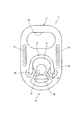
本発明に係るタブ1は、一例として、アルミニウム合金等からなる帯状金属板を素材としてプレス成形により所定の形状に切り抜かれて成形されるものであり、図1および図2に示す例では、指掛け部7が形成されている後方側が、角部を丸めた矩形状をなし、これに対して押し下げ部8側が円弧状に湾曲し、全体として、変形した長方形状に形成されており、その外周部が二重又は三重に折り曲げられてカール成形され、カール部9となっている。後方側に形成された指掛け部7は、タブ1の全体形状を長方形状とした場合に短辺に沿う方向に長い長孔であるリングホール10を備えており、その内周縁は、裏面側にカール成形されている。
As an example, the
前端部に形成されている押し下げ部8は、その外周縁が平面視で円弧状をなすように形成されている。その押し下げ部8の内周側からタブ1の後方に向けて(リングホール10側に向けて)延びる取り付け片11が形成されている。取り付け片11は、タブ1を構成している金属板からなる舌(タング)状(舌片状)の部分であり、缶蓋2におけるパネル部3に対面して接触している部分である。すなわち、取り付け片11の周りの約3/4の範囲には、タブ1を厚さ方向に打ち抜いた所定形状(例えばU字状)の切り込みであるタングホール12が形成されている。さらに、取り付け片11には、その板厚方向に貫通していてリベット部6が挿入されるリベットホール13が形成されている。
The push-down
押し下げ部8は、帯状金属板素材(図示せず)からタブ1を成形する間、タブ1を帯状金属板素材に連結・保持している連結部(図示せず)が切断された際のタブ1側の切断端部である切り離し凸部14と、切り離し凸部14の両側に形成され、縦断面が少なくとも金属板の三重構造となるようにカール加工された三重カール部15とを有している。切り離し凸部14は、三重カール部15間の隙間に収められ、かつ、押し下げ部8の外周縁から突出しないように同一外周縁上に成形されている。
The push-down
押し下げ部8と取り付け片11との間には、取り付け片11と押し下げ部8との間でこれら取り付け片11と押し下げ部8とを繋いでいる接続部分の上面は、下方(裏面側)に窪んでいて扇状の凹パネル部16として形成されている。すなわち、この凹パネル部16の底面は、取り付け片11の上面よりも下方に位置するように形成されている。
The upper surface of the connection portion connecting the
一方、タブ1の側部には、タブ1の長手方向に延びかつタブ1の表面側に突出した凸ビード17が左右に1本ずつ形成されており、タブ1を一つずつ積み重ねた際に、タブ1の裏面の側方のカール部9が凸ビード17に当接し、これら凸ビード17とカール部9とによって上下のタブ1の相互の位置合わせが可能なように構成されている。
On the other hand, on the side of the
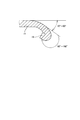
前述した取り付け片11を区画しているタングホール12は、取り付け片11の外周縁に沿って打ち抜かれたスリット状の部分であり、そのタングホール12の両端部分(タブ1の軸線方向において押し下げ部8側に位置する左右二箇所の端部)では、その周辺部がタブ1の水平方向(タブ1の表面に沿う方向)に対して斜め下方(裏面側)に傾斜しており、その周縁部に、図3に示すように、タングホール12の端縁部(U字状に切り抜かれた切断端)が折り返された折り返し部18が形成されている。折り返し部18は、タングホール12の端縁部における周縁部を90°〜180°(好ましくは120°〜180°、さらに好ましくは180°)の範囲で折り返して形成されており、また、両端部分の周辺部の傾斜角度は、タブ1の水平方向に対して20°〜90°(好ましくは30°〜80°)の範囲に設定されている。
The
折り返し部18は、タブ1の長手方向におけるタングホール12の両端からリベットホール13の中心に相当する位置までの範囲において、タングホール12の周縁部の内周側と外周側とに沿って連続して形成されていることが好ましい。
In the range from the both ends of the
このようなタブ1によれば、タングホール12の両端部分に、タングホール12の端縁部が折り返された折り返し部18が形成されていることにより、折り返し成形による金属板の加工硬化やタングホール12の両端部分における断面係数が大きくなることなどによってこの部分の強度が増す。言い換えれば、タブ1のいわゆる本体部分に対する取り付け片11の基部(もしくは連結部分)の破断強度が増大する。そのため、タブ1の指掛け部7を持ち上げた時にタングホール12の両端部分に捻れ力が加えられた場合でも、タングホール12の両端部分がその延長線方向に破断することを防止できる。
According to such a
また、折り返し部18が、端縁部を180°折り返すことで形成されていることにより、タングホール12の両端部分の板材が2枚重ねになっているため、タングホール12の両端部分をより破断しにくくすることができる。
Further, since the folded
さらに、折り返し部18が、タブ1の軸線方向(長手方向)において、タングホール12の両端からリベットホール13の中心に相当する位置までの範囲に形成されていることにより、開口操作時にタングホール12の両端部分の延長線方向に亀裂が生じることだけでなく、タングホール12の両端部分の延長線方向以外の部分に亀裂が生じることを防止できる。
Further, the folded
さらにまた、タングホール12の両端部分の周辺部が、タブ1の水平方向に対して斜め下方に傾斜していることにより、指掛け部7が勢いよく持ち上げられ、タングホール12の両端部分に更に強い捻れ力が加えられた場合でも、タングホール12の両端部分の周辺部に曲げ加工が加えられていてこの部分の強度が更に増大しているため、タングホール12の両端部分がその延長線方向に破断することを確実に防止できる。
Furthermore, since the peripheral portions of both end portions of the
したがって、本発明に係るタブによれば、取り付け片をタブのいわゆる本体の部分に連結している基部の強度、すなわちタングホールの両端部の強度をその折り返し部によって増大させることができるから、タブの素材である金属板を薄いものとすることができ、ひいてはタブや開口容易缶蓋の材料を少なくし、また環境負荷を低減することができる。 Therefore, according to the tab according to the present invention, the strength of the base connecting the mounting piece to the so-called main body portion of the tab, that is, the strength of both ends of the tongue hole can be increased by the folded portion. Therefore, the metal plate, which is the material of the above, can be made thin, and as a result, the material of the tab and the easy opening can lid can be reduced, and the environmental load can be reduced.
1…タブ、 2…開口容易缶蓋、 3…パネル部、 4…スコア線、 5…開口片、 6…リベット部、 7…指掛け部、 8…押し下げ部、 9…カール部、 10…リングホール、 11…取り付け片、 12…タングホール、 18…折り返し部。
DESCRIPTION OF
Claims (4)
前記タングホールの両端部分に、そのタングホールを形成している端縁部が折り返された折り返し部が形成されていることを特徴とする開口容易缶蓋用タブ。 A tongue-shaped attachment piece fixed by a rivet portion to a panel portion of a can lid in which a score line for partitioning an opening piece is engraved, a finger hook portion formed on one end side away from the rivet portion, A push-down portion formed on the opposite side of the finger-hanging portion with the rivet portion interposed therebetween, and a tongue hole that separates the attachment piece from other portions around the attachment piece, and lifts the finger-hanging portion In the tab for easy opening of the can lid that is configured to perform the opening operation of the can lid by the push-down portion due to the lever action,
A tab for an easy-to-open can lid, characterized in that a folded portion is formed at both end portions of the tongue hole by folding back the edge portion forming the tongue hole.
Priority Applications (1)
| Application Number | Priority Date | Filing Date | Title |
|---|---|---|---|
| JP2011063016A JP2012197103A (en) | 2011-03-22 | 2011-03-22 | Tab for easy-to-open can lid |
Applications Claiming Priority (1)
| Application Number | Priority Date | Filing Date | Title |
|---|---|---|---|
| JP2011063016A JP2012197103A (en) | 2011-03-22 | 2011-03-22 | Tab for easy-to-open can lid |
Publications (1)
| Publication Number | Publication Date |
|---|---|
| JP2012197103A true JP2012197103A (en) | 2012-10-18 |
Family
ID=47179760
Family Applications (1)
| Application Number | Title | Priority Date | Filing Date |
|---|---|---|---|
| JP2011063016A Pending JP2012197103A (en) | 2011-03-22 | 2011-03-22 | Tab for easy-to-open can lid |
Country Status (1)
| Country | Link |
|---|---|
| JP (1) | JP2012197103A (en) |
Cited By (1)
| Publication number | Priority date | Publication date | Assignee | Title |
|---|---|---|---|---|
| WO2020004066A1 (en) * | 2018-06-25 | 2020-01-02 | 東洋製罐株式会社 | Tab for opening can lid |
Citations (5)
| Publication number | Priority date | Publication date | Assignee | Title |
|---|---|---|---|---|
| JPS6127821U (en) * | 1984-07-24 | 1986-02-19 | 東洋製罐株式会社 | Pull tab for easy opening |
| JP2002336925A (en) * | 2001-05-11 | 2002-11-26 | Mitsubishi Materials Corp | Method of manufacturing can opening tab |
| JP2002346673A (en) * | 2001-05-22 | 2002-12-03 | Mitsubishi Materials Corp | Manufacturing method for can opening tab and can lid |
| JP2007021564A (en) * | 2005-07-20 | 2007-02-01 | Universal Seikan Kk | Tab manufacturing method, tab and can lid |
| JP2010179924A (en) * | 2009-02-03 | 2010-08-19 | Daiwa Can Co Ltd | Tab for stay-on-tab type can lid, and method for manufacturing the same |
-
2011
- 2011-03-22 JP JP2011063016A patent/JP2012197103A/en active Pending
Patent Citations (5)
| Publication number | Priority date | Publication date | Assignee | Title |
|---|---|---|---|---|
| JPS6127821U (en) * | 1984-07-24 | 1986-02-19 | 東洋製罐株式会社 | Pull tab for easy opening |
| JP2002336925A (en) * | 2001-05-11 | 2002-11-26 | Mitsubishi Materials Corp | Method of manufacturing can opening tab |
| JP2002346673A (en) * | 2001-05-22 | 2002-12-03 | Mitsubishi Materials Corp | Manufacturing method for can opening tab and can lid |
| JP2007021564A (en) * | 2005-07-20 | 2007-02-01 | Universal Seikan Kk | Tab manufacturing method, tab and can lid |
| JP2010179924A (en) * | 2009-02-03 | 2010-08-19 | Daiwa Can Co Ltd | Tab for stay-on-tab type can lid, and method for manufacturing the same |
Cited By (4)
| Publication number | Priority date | Publication date | Assignee | Title |
|---|---|---|---|---|
| WO2020004066A1 (en) * | 2018-06-25 | 2020-01-02 | 東洋製罐株式会社 | Tab for opening can lid |
| JP2020001710A (en) * | 2018-06-25 | 2020-01-09 | 東洋製罐株式会社 | Tab for opening can lid |
| CN112368218A (en) * | 2018-06-25 | 2021-02-12 | 东洋制罐株式会社 | Ring tab for opening can lid |
| JP7210821B2 (en) | 2018-06-25 | 2023-01-24 | 東洋製罐株式会社 | Tab for can lid opening |
Similar Documents
| Publication | Publication Date | Title |
|---|---|---|
| JP4883995B2 (en) | Can lid with score line | |
| JP6131076B2 (en) | Manufacturing method of can lid | |
| JP4776430B2 (en) | Can lid | |
| JP2012197103A (en) | Tab for easy-to-open can lid | |
| JP5514665B2 (en) | Can lid and tab for can lid | |
| JP2004161360A (en) | Easily openable can lid | |
| JP5475556B2 (en) | Method for manufacturing can lid and tab | |
| JP7271549B2 (en) | can lid | |
| JP5246858B2 (en) | Easy-to-open can lid | |
| JP3158431U (en) | Pull tab structure of can container | |
| JP2021187471A (en) | Can-top | |
| JP4895573B2 (en) | Easy-to-open can lid tab and method for forming tab | |
| JP5411520B2 (en) | Steion tab type tab for can lid | |
| JP3117389U (en) | Can lid | |
| JP4681354B2 (en) | Easy-to-open can lid | |
| CN108473230B (en) | Lid for beverage can | |
| JP5658940B2 (en) | Can lid | |
| JP4187144B2 (en) | Easy opening can lid | |
| JPH0744595Y2 (en) | Easy open can lid | |
| JP2015071436A (en) | Can-top | |
| JP2022119586A (en) | Can lid and manufacturing method of the same | |
| JP2017137078A (en) | Can top | |
| JP2015205701A (en) | Easy openable can lid | |
| JP2015209231A (en) | Canned food lid | |
| JP5663232B2 (en) | Can lid |
Legal Events
| Date | Code | Title | Description |
|---|---|---|---|
| A621 | Written request for application examination |
Free format text: JAPANESE INTERMEDIATE CODE: A621 Effective date: 20140224 |
|
| A977 | Report on retrieval |
Free format text: JAPANESE INTERMEDIATE CODE: A971007 Effective date: 20141126 |
|
| A131 | Notification of reasons for refusal |
Free format text: JAPANESE INTERMEDIATE CODE: A131 Effective date: 20141202 |
|
| A02 | Decision of refusal |
Free format text: JAPANESE INTERMEDIATE CODE: A02 Effective date: 20150331 |